EP2998542A1 - Pre-cooler inlet duct that utilize active flow-control and method including the same - Google Patents
Pre-cooler inlet duct that utilize active flow-control and method including the same Download PDFInfo
- Publication number
- EP2998542A1 EP2998542A1 EP15183727.5A EP15183727A EP2998542A1 EP 2998542 A1 EP2998542 A1 EP 2998542A1 EP 15183727 A EP15183727 A EP 15183727A EP 2998542 A1 EP2998542 A1 EP 2998542A1
- Authority
- EP
- European Patent Office
- Prior art keywords
- flow
- inlet duct
- cooler inlet
- boundary layer
- cooler
- Prior art date
- Legal status (The legal status is an assumption and is not a legal conclusion. Google has not performed a legal analysis and makes no representation as to the accuracy of the status listed.)
- Granted
Links
- 238000000034 method Methods 0.000 title claims abstract description 49
- 239000012530 fluid Substances 0.000 claims abstract description 114
- 238000000926 separation method Methods 0.000 claims abstract description 25
- 238000002347 injection Methods 0.000 claims description 67
- 239000007924 injection Substances 0.000 claims description 67
- 238000010408 sweeping Methods 0.000 claims description 4
- 238000001816 cooling Methods 0.000 description 23
- 230000000712 assembly Effects 0.000 description 9
- 238000000429 assembly Methods 0.000 description 9
- 230000006870 function Effects 0.000 description 7
- 230000007423 decrease Effects 0.000 description 6
- 238000002485 combustion reaction Methods 0.000 description 3
- 230000003247 decreasing effect Effects 0.000 description 3
- 229910001285 shape-memory alloy Inorganic materials 0.000 description 3
- 230000009471 action Effects 0.000 description 2
- 230000008859 change Effects 0.000 description 2
- 230000000694 effects Effects 0.000 description 2
- 239000000446 fuel Substances 0.000 description 2
- 230000009467 reduction Effects 0.000 description 1
Images


Classifications
-
- F—MECHANICAL ENGINEERING; LIGHTING; HEATING; WEAPONS; BLASTING
- F02—COMBUSTION ENGINES; HOT-GAS OR COMBUSTION-PRODUCT ENGINE PLANTS
- F02C—GAS-TURBINE PLANTS; AIR INTAKES FOR JET-PROPULSION PLANTS; CONTROLLING FUEL SUPPLY IN AIR-BREATHING JET-PROPULSION PLANTS
- F02C6/00—Plural gas-turbine plants; Combinations of gas-turbine plants with other apparatus; Adaptations of gas- turbine plants for special use
- F02C6/04—Gas-turbine plants providing heated or pressurised working fluid for other apparatus, e.g. without mechanical power output
- F02C6/06—Gas-turbine plants providing heated or pressurised working fluid for other apparatus, e.g. without mechanical power output providing compressed gas
- F02C6/08—Gas-turbine plants providing heated or pressurised working fluid for other apparatus, e.g. without mechanical power output providing compressed gas the gas being bled from the gas-turbine compressor
-
- B—PERFORMING OPERATIONS; TRANSPORTING
- B64—AIRCRAFT; AVIATION; COSMONAUTICS
- B64D—EQUIPMENT FOR FITTING IN OR TO AIRCRAFT; FLIGHT SUITS; PARACHUTES; ARRANGEMENTS OR MOUNTING OF POWER PLANTS OR PROPULSION TRANSMISSIONS IN AIRCRAFT
- B64D33/00—Arrangements in aircraft of power plant parts or auxiliaries not otherwise provided for
- B64D33/02—Arrangements in aircraft of power plant parts or auxiliaries not otherwise provided for of combustion air intakes
-
- B—PERFORMING OPERATIONS; TRANSPORTING
- B64—AIRCRAFT; AVIATION; COSMONAUTICS
- B64D—EQUIPMENT FOR FITTING IN OR TO AIRCRAFT; FLIGHT SUITS; PARACHUTES; ARRANGEMENTS OR MOUNTING OF POWER PLANTS OR PROPULSION TRANSMISSIONS IN AIRCRAFT
- B64D33/00—Arrangements in aircraft of power plant parts or auxiliaries not otherwise provided for
- B64D33/08—Arrangements in aircraft of power plant parts or auxiliaries not otherwise provided for of power plant cooling systems
- B64D33/10—Radiator arrangement
-
- F—MECHANICAL ENGINEERING; LIGHTING; HEATING; WEAPONS; BLASTING
- F01—MACHINES OR ENGINES IN GENERAL; ENGINE PLANTS IN GENERAL; STEAM ENGINES
- F01D—NON-POSITIVE DISPLACEMENT MACHINES OR ENGINES, e.g. STEAM TURBINES
- F01D25/00—Component parts, details, or accessories, not provided for in, or of interest apart from, other groups
- F01D25/08—Cooling; Heating; Heat-insulation
- F01D25/12—Cooling
- F01D25/125—Cooling of bearings
-
- F—MECHANICAL ENGINEERING; LIGHTING; HEATING; WEAPONS; BLASTING
- F02—COMBUSTION ENGINES; HOT-GAS OR COMBUSTION-PRODUCT ENGINE PLANTS
- F02C—GAS-TURBINE PLANTS; AIR INTAKES FOR JET-PROPULSION PLANTS; CONTROLLING FUEL SUPPLY IN AIR-BREATHING JET-PROPULSION PLANTS
- F02C7/00—Features, components parts, details or accessories, not provided for in, or of interest apart form groups F02C1/00 - F02C6/00; Air intakes for jet-propulsion plants
- F02C7/12—Cooling of plants
- F02C7/14—Cooling of plants of fluids in the plant, e.g. lubricant or fuel
- F02C7/141—Cooling of plants of fluids in the plant, e.g. lubricant or fuel of working fluid
-
- F—MECHANICAL ENGINEERING; LIGHTING; HEATING; WEAPONS; BLASTING
- F02—COMBUSTION ENGINES; HOT-GAS OR COMBUSTION-PRODUCT ENGINE PLANTS
- F02C—GAS-TURBINE PLANTS; AIR INTAKES FOR JET-PROPULSION PLANTS; CONTROLLING FUEL SUPPLY IN AIR-BREATHING JET-PROPULSION PLANTS
- F02C7/00—Features, components parts, details or accessories, not provided for in, or of interest apart form groups F02C1/00 - F02C6/00; Air intakes for jet-propulsion plants
- F02C7/12—Cooling of plants
- F02C7/16—Cooling of plants characterised by cooling medium
- F02C7/18—Cooling of plants characterised by cooling medium the medium being gaseous, e.g. air
- F02C7/185—Cooling means for reducing the temperature of the cooling air or gas
-
- F—MECHANICAL ENGINEERING; LIGHTING; HEATING; WEAPONS; BLASTING
- F02—COMBUSTION ENGINES; HOT-GAS OR COMBUSTION-PRODUCT ENGINE PLANTS
- F02C—GAS-TURBINE PLANTS; AIR INTAKES FOR JET-PROPULSION PLANTS; CONTROLLING FUEL SUPPLY IN AIR-BREATHING JET-PROPULSION PLANTS
- F02C9/00—Controlling gas-turbine plants; Controlling fuel supply in air- breathing jet-propulsion plants
- F02C9/16—Control of working fluid flow
-
- B—PERFORMING OPERATIONS; TRANSPORTING
- B64—AIRCRAFT; AVIATION; COSMONAUTICS
- B64C—AEROPLANES; HELICOPTERS
- B64C21/00—Influencing air flow over aircraft surfaces by affecting boundary layer flow
- B64C21/02—Influencing air flow over aircraft surfaces by affecting boundary layer flow by use of slot, ducts, porous areas or the like
- B64C21/04—Influencing air flow over aircraft surfaces by affecting boundary layer flow by use of slot, ducts, porous areas or the like for blowing
-
- B—PERFORMING OPERATIONS; TRANSPORTING
- B64—AIRCRAFT; AVIATION; COSMONAUTICS
- B64C—AEROPLANES; HELICOPTERS
- B64C21/00—Influencing air flow over aircraft surfaces by affecting boundary layer flow
- B64C21/02—Influencing air flow over aircraft surfaces by affecting boundary layer flow by use of slot, ducts, porous areas or the like
- B64C21/06—Influencing air flow over aircraft surfaces by affecting boundary layer flow by use of slot, ducts, porous areas or the like for sucking
-
- B—PERFORMING OPERATIONS; TRANSPORTING
- B64—AIRCRAFT; AVIATION; COSMONAUTICS
- B64D—EQUIPMENT FOR FITTING IN OR TO AIRCRAFT; FLIGHT SUITS; PARACHUTES; ARRANGEMENTS OR MOUNTING OF POWER PLANTS OR PROPULSION TRANSMISSIONS IN AIRCRAFT
- B64D13/00—Arrangements or adaptations of air-treatment apparatus for aircraft crew or passengers, or freight space, or structural parts of the aircraft
- B64D13/06—Arrangements or adaptations of air-treatment apparatus for aircraft crew or passengers, or freight space, or structural parts of the aircraft the air being conditioned
- B64D2013/0603—Environmental Control Systems
- B64D2013/0618—Environmental Control Systems with arrangements for reducing or managing bleed air, using another air source, e.g. ram air
-
- B—PERFORMING OPERATIONS; TRANSPORTING
- B64—AIRCRAFT; AVIATION; COSMONAUTICS
- B64D—EQUIPMENT FOR FITTING IN OR TO AIRCRAFT; FLIGHT SUITS; PARACHUTES; ARRANGEMENTS OR MOUNTING OF POWER PLANTS OR PROPULSION TRANSMISSIONS IN AIRCRAFT
- B64D33/00—Arrangements in aircraft of power plant parts or auxiliaries not otherwise provided for
- B64D33/02—Arrangements in aircraft of power plant parts or auxiliaries not otherwise provided for of combustion air intakes
- B64D2033/0226—Arrangements in aircraft of power plant parts or auxiliaries not otherwise provided for of combustion air intakes comprising boundary layer control means
-
- B—PERFORMING OPERATIONS; TRANSPORTING
- B64—AIRCRAFT; AVIATION; COSMONAUTICS
- B64D—EQUIPMENT FOR FITTING IN OR TO AIRCRAFT; FLIGHT SUITS; PARACHUTES; ARRANGEMENTS OR MOUNTING OF POWER PLANTS OR PROPULSION TRANSMISSIONS IN AIRCRAFT
- B64D33/00—Arrangements in aircraft of power plant parts or auxiliaries not otherwise provided for
- B64D33/02—Arrangements in aircraft of power plant parts or auxiliaries not otherwise provided for of combustion air intakes
- B64D2033/0266—Arrangements in aircraft of power plant parts or auxiliaries not otherwise provided for of combustion air intakes specially adapted for particular type of power plants
- B64D2033/0286—Arrangements in aircraft of power plant parts or auxiliaries not otherwise provided for of combustion air intakes specially adapted for particular type of power plants for turbofan engines
-
- F—MECHANICAL ENGINEERING; LIGHTING; HEATING; WEAPONS; BLASTING
- F05—INDEXING SCHEMES RELATING TO ENGINES OR PUMPS IN VARIOUS SUBCLASSES OF CLASSES F01-F04
- F05D—INDEXING SCHEME FOR ASPECTS RELATING TO NON-POSITIVE-DISPLACEMENT MACHINES OR ENGINES, GAS-TURBINES OR JET-PROPULSION PLANTS
- F05D2210/00—Working fluids
- F05D2210/30—Flow characteristics
-
- F—MECHANICAL ENGINEERING; LIGHTING; HEATING; WEAPONS; BLASTING
- F05—INDEXING SCHEMES RELATING TO ENGINES OR PUMPS IN VARIOUS SUBCLASSES OF CLASSES F01-F04
- F05D—INDEXING SCHEME FOR ASPECTS RELATING TO NON-POSITIVE-DISPLACEMENT MACHINES OR ENGINES, GAS-TURBINES OR JET-PROPULSION PLANTS
- F05D2270/00—Control
- F05D2270/01—Purpose of the control system
- F05D2270/17—Purpose of the control system to control boundary layer
-
- F—MECHANICAL ENGINEERING; LIGHTING; HEATING; WEAPONS; BLASTING
- F15—FLUID-PRESSURE ACTUATORS; HYDRAULICS OR PNEUMATICS IN GENERAL
- F15D—FLUID DYNAMICS, i.e. METHODS OR MEANS FOR INFLUENCING THE FLOW OF GASES OR LIQUIDS
- F15D1/00—Influencing flow of fluids
- F15D1/002—Influencing flow of fluids by influencing the boundary layer
- F15D1/0065—Influencing flow of fluids by influencing the boundary layer using active means, e.g. supplying external energy or injecting fluid
- F15D1/008—Influencing flow of fluids by influencing the boundary layer using active means, e.g. supplying external energy or injecting fluid comprising fluid injection or suction means
-
- F—MECHANICAL ENGINEERING; LIGHTING; HEATING; WEAPONS; BLASTING
- F15—FLUID-PRESSURE ACTUATORS; HYDRAULICS OR PNEUMATICS IN GENERAL
- F15D—FLUID DYNAMICS, i.e. METHODS OR MEANS FOR INFLUENCING THE FLOW OF GASES OR LIQUIDS
- F15D1/00—Influencing flow of fluids
- F15D1/02—Influencing flow of fluids in pipes or conduits
- F15D1/06—Influencing flow of fluids in pipes or conduits by influencing the boundary layer
-
- Y—GENERAL TAGGING OF NEW TECHNOLOGICAL DEVELOPMENTS; GENERAL TAGGING OF CROSS-SECTIONAL TECHNOLOGIES SPANNING OVER SEVERAL SECTIONS OF THE IPC; TECHNICAL SUBJECTS COVERED BY FORMER USPC CROSS-REFERENCE ART COLLECTIONS [XRACs] AND DIGESTS
- Y02—TECHNOLOGIES OR APPLICATIONS FOR MITIGATION OR ADAPTATION AGAINST CLIMATE CHANGE
- Y02T—CLIMATE CHANGE MITIGATION TECHNOLOGIES RELATED TO TRANSPORTATION
- Y02T50/00—Aeronautics or air transport
- Y02T50/50—On board measures aiming to increase energy efficiency
-
- Y—GENERAL TAGGING OF NEW TECHNOLOGICAL DEVELOPMENTS; GENERAL TAGGING OF CROSS-SECTIONAL TECHNOLOGIES SPANNING OVER SEVERAL SECTIONS OF THE IPC; TECHNICAL SUBJECTS COVERED BY FORMER USPC CROSS-REFERENCE ART COLLECTIONS [XRACs] AND DIGESTS
- Y02—TECHNOLOGIES OR APPLICATIONS FOR MITIGATION OR ADAPTATION AGAINST CLIMATE CHANGE
- Y02T—CLIMATE CHANGE MITIGATION TECHNOLOGIES RELATED TO TRANSPORTATION
- Y02T50/00—Aeronautics or air transport
- Y02T50/60—Efficient propulsion technologies, e.g. for aircraft
Definitions
- the present disclosure relates to pre-cooler inlet ducts for nacelles of jet engines, and more particularly to pre-cooler inlet ducts that utilize active flow-control to interact with, modify, and/or energize a boundary layer fluid flow within a boundary layer adjacent to the pre-cooler inlet duct, and to systems and methods including the pre-cooler inlet duct.
- Nacelles for jet engines may include a pre-cooler inlet duct that may direct a pre-cooler air stream onto a heat exchanger assembly to cool engine bleed air prior to it being utilized by the jet engine and/or by another component of an aircraft that includes the jet engine.
- the pre-cooler inlet duct may be present within the nacelle and may be located to receive a portion of a compressed air stream that may be pressurized by a compressor of the jet engine.
- a size of the pre-cooler inlet may be restricted by a size of the nacelle.
- a given size pre-cooler inlet may dictate a needed size for a nacelle that may contain the pre-cooler inlet.
- a desired flow rate of the pre-cooler air stream also may dictate a needed size for the pre-cooler inlet duct.
- Pre-cooler inlet ducts that utilize active flow-control and systems and methods including the same are disclosed herein.
- the systems include a pre-cooler inlet duct for a jet engine that is configured to receive a pre-cooler air stream and to direct the pre-cooler air stream into a heat exchanger.
- the pre-cooler inlet duct includes a flow-directing surface, which defines at least a portion of the pre-cooler inlet duct, and an active flow-control device.
- the active flow-control device is located to modify a boundary layer fluid flow within a boundary layer adjacent the flow-directing surface, such as to resist separation of the boundary layer from the flow-directing surface when the pre-cooler air stream flows through the pre-cooler inlet duct.
- the active flow-control device may modify the boundary layer in any suitable manner, such as by interacting with and/or energizing the boundary layer, to resist separation of the boundary layer from the flow-directing surface.
- a radius of curvature of the flow-directing surface is less than a radius of curvature of a conventional flow-directing surface that does not include the active flow-control device. In some embodiments, a length of the flow-directing surface is less than a length of the conventional flow-directing surface.
- the active flow-control device is configured to inject a flow-control fluid stream into the boundary layer through an injection orifice. In some embodiments, the injection orifice forms a portion of a sweeping jet. In some embodiments, the active flow-control device is configured to continuously inject the flow-control fluid stream. In some embodiments, the active flow-control device is configured to intermittently inject the flow-control fluid stream. In some embodiments, the active flow-control device is configured to inject a plurality of flow-control fluid streams. In some embodiments, the active flow-control device is configured to vary which of the plurality of flow-control fluid streams is being injected at a given point in time.
- the active flow-control device includes a vortex generator configured to generate a vortex within the boundary layer. In some embodiments, the active flow-control device includes a suction assembly configured to remove a suction stream from the boundary layer.
- the pre-cooler inlet duct forms a portion of a nacelle for a jet engine. In some embodiments, the nacelle forms a portion of an aircraft.
- the methods include methods of resisting boundary layer separation in the pre-cooler inlet duct.
- the methods include flowing the pre-cooler air stream across the flow-directing surface to generate a boundary layer adjacent the flow-directing surface.
- the methods further include modifying the boundary layer with the active flow-control device to resist separation of the boundary layer from the flow-directing surface.
- Figs. 1-8 provide illustrative, non-exclusive examples of pre-cooler inlet ducts 100 that include active flow-control devices 150 according to the present disclosure, of nacelles 54 for jet engines 40 that include pre-cooler inlet ducts 100, of aircraft 20 that include jet engines 40, and/or of methods of operating the same.
- Elements that serve a similar, or at least substantially similar, purpose are labeled with like numbers in each of Figs. 1-8 , and these elements may not be discussed in detail herein with reference to each of Figs. 1-8 .
- all elements may not be labeled in each of Figs. 1-8 , but reference numerals associated therewith may be utilized herein for consistency.
- Elements, components, and/or features that are discussed herein with reference to one or more of Figs. 1-8 may be included in and/or utilized with any of Figs. 1-8 without departing from the scope of the present disclosure.
- Fig. 1 is a schematic representation of an illustrative, non-exclusive example of an aircraft 20 that may include a jet engine 40 that includes a pre-cooling assembly 60 with a pre-cooler inlet duct 100 according to the present disclosure
- Figs. 2-3 are more detailed but still illustrative, non-exclusive examples of a jet engine 40 that includes a pre-cooling assembly 60 with a pre-cooler inlet duct 100 according to the present disclosure.
- Fig. 2 is a schematic partially fragmentary side view of jet engines 40
- Fig. 3 is a schematic front view of jet engines 40.
- aircraft 20 includes an airframe 30, which is operatively attached to and/or configured to support one or more jet engines 40.
- jet engines 40 may include a nacelle 54 that may be sized and/or shaped to define, contain, and/or house a variety of components of jet engine 40.
- jet engines 40 may include an inlet 42, which is configured to receive an air stream 43, and a compressor 44, which is configured to compress (or increase a pressure of) air stream 43 to generate a compressed air stream 45.
- Jet engines 40 also may include a burner 46, which is configured to combust a fuel stream with a portion 53 of compressed air stream 45 to generate a combustion stream, and a turbine 48, which is configured to be powered by the combustion stream and to power compressor 44.
- jet engines 40 further may include a nozzle 50, which is configured to permit the combustion stream to be expelled from (or to exit) jet engine 40.
- jet engines 40 may define a central duct 52, which is configured to receive portion 53 of compressed air stream 45 from compressor 44, and pre-cooler inlet duct 100, which is configured to receive another portion of compressed air stream 45, which is referred to herein as a pre-cooler air stream 65.
- Pre-cooler inlet duct 100 may form a portion of pre-cooling assembly 60 and may provide and/or direct pre-cooler air stream 65 to and/or toward a heat exchanger 66.
- Heat exchanger 66 may be configured to exchange thermal energy with pre-cooler air stream 65 to generate a heat-exchanged air stream 67. Heat-exchanged air stream 67 may be provided to another component of jet engine 40 and/or of aircraft 20.
- an active flow-control device 150 may be configured, utilized, and/or operated to resist separation of a boundary layer 80, which includes a boundary layer fluid flow 82, from a flow-directing surface 140 of pre-cooler inlet duct 100.
- active flow-control device 150 may be configured to modify boundary layer fluid flow 82, thereby changing one or more characteristics of boundary layer fluid flow 82 and permitting boundary layer fluid flow 82 to flow across flow-directing surface 140 without separation therefrom.
- pre-cooling assemblies 60 and/or pre-cooler inlet ducts 100 may be configured to maintain and/or retain boundary layer 80 attached to flow-directing surface 140 over a wide range of average pre-cooler air stream speeds of pre-cooler air stream 65.
- pre-cooling assemblies 60 and/or pre-cooler inlet ducts 100 may maintain boundary layer 80 attached to pre-cooler inlet duct 100 when the average pre-cooler air stream speed is at least 50 meters/second (m/s), at least 75 m/s, at least 100 m/s, at least 125 m/s, at least 150 m/s, at least 175 m/s, at least 200 m/s, at least 225 m/s, at least 250 m/s, at least 275 m/s, and/or at least 300 m/s.
- m/s average pre-cooler air stream speed
- pre-cooling assemblies 60 also may maintain boundary layer 80 attached to flow-directing surface 140 when the average pre-cooler air stream speed is less than 350 m/s, less than 325 m/s, less than 300 m/s, less than 275 m/s, less than 250 m/s, less than 225 m/s, and/or less than 200 m/s.
- Active flow-control device 150 may include and/or utilize any suitable active flow-control technology. As an illustrative, non-exclusive example, and as discussed in more detail herein, active flow-control device 150 may be configured to inject a flow-control fluid stream into boundary layer 80. As another illustrative, non-exclusive example, active flow-control device 150 may include a vortex generator that is configured to generate a vortex within boundary layer 80. As yet another illustrative, non-exclusive example, active flow-control device 150 may be configured to remove a suction stream from boundary layer 80.
- active flow-control device 150 may supply the flow-control fluid stream, may generate the vortex, and/or may remove the suction stream in any suitable manner and/or utilizing any suitable equipment.
- active flow-control device 150 may include one or more of a piezoelectric actuator, a shape memory alloy actuator, a diaphragm, a pump, a compressor, and/or a fan.
- pre-cooling assembly 60 and pre-cooler inlet duct 100 thereof may be located within an internal volume 56 of nacelle 54.
- a size, shape, and/or volume of pre-cooling assembly 60 and/or of pre-cooler inlet duct 100 may be constrained by a target, desired, and/or specified size of nacelle 54 and/or by a size and/or geometry of the other components that may be present within internal volume 56.
- pre-cooler air stream 65 (as illustrated in Fig. 2 ) into pre-cooler inlet duct 100 without increasing the size of nacelle 54, and pre-cooling assemblies 60 with bifurcated pre-cooler inlets have been utilized to provide for this increase in flow rate of pre-cooler air stream 65.
- Such a bifurcated pre-cooler inlet includes two pre-cooler inlet ducts 100.
- One of these pre-cooler inlet ducts 100 is illustrated in solid lines in Fig. 3 , while the other pre-cooler inlet duct 100 is illustrated in dashed lines to indicate that the second pre-cooler inlet duct may be optional.
- pre-cooler inlets may provide for a measurable increase in the flow rate of pre-cooler air stream 65
- Figs. 4-5 provide schematic cross-sectional views of illustrative, non-exclusive examples of pre-cooler inlet ducts 100 that may be utilized in pre-cooling assemblies 60 according to the present disclosure.
- the schematic cross-sectional views of Figs. 4-5 may be taken along line A-A of Fig. 3 .
- pre-cooling assemblies 60 include one or more pre-cooler inlet ducts 100.
- Pre-cooler inlet duct 100 may be at least partially defined by one or more flow-directing surfaces 140 and may be configured to direct a pre-cooler air stream 65 toward and/or into contact with a heat exchanger 66.
- Heat exchanger 66 receives pre-cooler air stream 65 and produces heat-exchanged air stream 67 therefrom.
- pre-cooling assembly 60 includes a bifurcated pre-cooler inlet that includes two pre-cooler inlet ducts 100.
- pre-cooling assembly 60 of Fig. 5 includes a single pre-cooler inlet duct 100.
- one or more flow-directing surface 140 may include and/or utilize one or more active flow-control devices 150.
- Active flow-control devices 150 may be configured to resist separation of a boundary layer fluid flow 82 of a boundary layer 80 from respective flow-directing surfaces 140, as illustrated in Fig. 6 and discussed in more detail herein.
- the presence of active flow-control devices 150 may permit a decrease in one or more dimensions of pre-cooler inlet ducts 100 and/or of pre-cooling assembly 60 and/or may permit pre-cooling assemblies 60 to utilize a single pre-cooler inlet duct 100 (as illustrated in Fig.
- a size of a pre-cooler inlet duct 10 and/or pre-cooling assembly 60 may be reduced without reduction in performance of the pre-cooling assembly 60.
- Active flow-control devices 150 are illustrated in dashed lines in Figs. 4-5 to indicate that active flow-control devices 150 may be located and/or present on any suitable flow-directing surface 140 of pre-cooler inlet ducts 100 according to the present disclosure.
- active flow-control devices 150 may be located on multiple (i.e., two or more) flow-directing surfaces 140 that define a given pre-cooler inlet duct 100 (e.g. opposing surfaces 140 of upper and/or lower pre-cooler inlet duct 100 in Fig. 4 or opposing surfaces 140 of the single pre-cooler inlet duct 100 in Fig. 5 ).
- active flow-control devices 150 may be located on one flow-directing surface 140 that defines the given pre-cooler inlet duct 100 but not on another flow-directing surface 140 that defines the given pre-cooler inlet duct 100.
- flow-control devices 150 may be located on portion(s) of flow-directing surfaces 140 where a large change in direction of boundary layer fluid flow 82 (illustrated in Fig. 6 ) is present. This may include portion(s) of flow-directing surfaces 140 that have and/or define a (relatively) smaller radius of curvature 104, as discussed herein with reference to Figs. 6-7 .
- Fig. 6 is a schematic cross-sectional view of a portion of a pre-cooling assembly 60 including a pre-cooler inlet duct 100 that is at least partially defined by a flow-directing surface 140 according to the present disclosure.
- flow-directing surface 140 includes one or more active flow-control devices 150 according to the present disclosure.
- active flow-control devices 150 may be configured to interact with, modify, and/or energize a boundary layer fluid flow 82 that is present within a boundary layer 80 of a pre-cooler air stream 65 that is flowing past flow-directing surface 140 to resist separation of boundary layer 80 from flow-directing surface 140. This may be accomplished in any suitable manner.
- active flow-control device 150 maybe configured to inject one or more flow-control fluid streams 152 into boundary layer 80 through an injection orifice 154 that may be defined by, within, and/or on flow-directing surface 140.
- Flow-control fluid stream 152 may be injected into boundary layer 80 in any suitable manner.
- flow-control fluid stream 152 may be injected at a flow speed, or average flow speed, of at least 100 meters/second (m/s), at least 125 m/s, at least 150 m/s, at least 175 m/s, at least 200 m/s, at least 225 m/s, at least 250 m/s, at least 275 m/s, at least 300 m/s, at least 350 m/s, at least 400 m/s, at least 450 m/s, or at least 500 m/s.
- flow-control fluid stream 152 may be injected at a flow speed, or average flow speed, of less than 700 m/s, less than 650 m/s, less than 600 m/s, less than 550 m/s, less than 500 m/s, less than 450 m/s, less than 400 m/s, less than 350 m/s, less than 325 m/s, less than 300 m/s, less than 275 m/s, less than 250 m/s, less than 225 m/s, and/or less than 200 m/s.
- flow-control fluid stream 152 may be injected through injection orifice 154 such that a pressure differential across the injection orifice is at least 1 kilopascal (kPa), at least 5 kPa, at least 10 kPa, at least 15 kPa, at least 20 kPa, at least 25 kPa, at least 30 kPa, at least 35 kPa, at least 40 kPa, at least 50 kPa, at least 75 kPa, at least 100 kPa, at least 150 kPa, at least 200 kPa, at least 300 kPa, at least 400 kPa, at least 500 kPa, at least 600 kPa, and/or at least 700 kPa.
- kPa kilopascal
- active flow-control device 150 may be configured to continuously, or at least substantially continuously, inject flow-control fluid stream 152 into boundary layer 80 when pre-cooler air stream 65 is flowing past flow-directing surface 140. Additionally or alternatively, it is also within the scope of the present disclosure that active flow-control device 150 may be configured to intermittently, selectively, and/or periodically inject flow-control fluid stream 152 into boundary layer 80 when pre-cooler air stream 65 is flowing past flow-directing surface 140.
- Flow-control fluid stream 152 may be injected into boundary layer 80 at any suitable location.
- active flow-control device 150 may be configured to inject a plurality of flow-control fluid streams 152 into boundary layer 80. This may include injecting the plurality of flow-control fluid streams in a spaced-apart manner around a curvature, or radius of curvature, 104 of flow-directing surface 140, as illustrated in Fig. 6 . Additionally or alternatively, this also may include injecting the plurality of flow-control fluid streams in a spaced-apart manner along a length of flow-directing surface 140 (i.e., in a spaced-apart manner along the Z-axis of Fig. 6 ).
- flow-control fluid stream 152 may be injected behind, downstream of, and/or on a lee side of a step 130 on a surface of flow-directing surface 140.
- Step 130 may include and/or be any suitable discontinuity and/or change in profile of flow-directing surface 140 and also may be referred to herein as a discontinuity 130.
- Flow-control fluid stream 152 may be generated in any suitable manner.
- flow-control fluid stream 152 may include and/or be a portion of compressed air stream 45 that is generated by jet engine 40 and/or by compressor 44 thereof (as illustrated in Figs. 1-2 ). Additionally or alternatively, flow-control fluid stream 152 may include and/or be a synthetic jet that is generated by a synthetic jet generator 158.
- active flow-control device 150 may include a suction assembly 160 that is configured to withdraw a suction stream 161 from boundary layer 80.
- active flow-control device 150 may include a vortex generator 156 that is configured to generate a vortex 157 within boundary layer 80.
- Vortex generator 156 may include any suitable active and/or passive vortex generator 156 that is configured to generate vortex 157 in any suitable manner.
- vortex generator 156 may include a physical obstruction and/or a vortex generator jet actuator.
- flow-control fluid stream 152 may be injected with any suitable orientation and/or at any suitable angle, or injection angle.
- flow-control fluid stream 152 may be injected into boundary layer 80 at a first injection angle 170.
- First injection angle 170 may be measured in a first plane that is parallel to a surface normal direction 168 of flow-directing surface 140, and it is within the scope of the present disclosure that first injection angle 170 may include and/or be any suitable angle.
- the first plane also may be perpendicular to a length of flow-directing surface 140 (i.e., the Z-direction in Fig. 6 ).
- flow-control fluid stream 152 also may be injected into boundary layer 80 at a second injection angle 174.
- Second injection angle 174 may be measured in a second plane that is parallel to surface normal direction 168 and perpendicular to the first plane, and it is within the scope of the present disclosure that second injection angle 174 may include any suitable angle.
- the second plane also may be parallel to the length of flow-directing surface 140.
- first injection angle 170 and/or second injection angle 174 include angles of at least 0 degrees, at least 5 degrees, at least 10 degrees, at least 15 degrees, at least 20 degrees, at least 30 degrees, at least 40 degrees, at least 50 degrees, at least 60 degrees, at least 70 degrees, at least 80 degrees, at least 90 degrees, at least 100 degrees, at least 110 degrees, at least 120 degrees, at least 130 degrees, at least 140 degrees, at least 150 degrees, at least 160 degrees, and/or at least 170 degrees.
- first injection angle 170 and/or second injection angle 174 may include angles of less than 180 degrees, less than 170 degrees, less than 160 degrees, less than 150 degrees, less than 140 degrees, less than 130 degrees, less than 120 degrees, less than 110 degrees, less than 100 degrees, less than 90 degrees, less than 80 degrees, less than 70 degrees, less than 60 degrees, less than 50 degrees, less than 40 degrees, less than 30 degrees, less than 20 degrees, less than 15 degrees, less than 10 degrees, and/or less than 5 degrees.
- first injection angle 170 and/or second injection angle 174 may be a variable angle that varies between any of the above-listed lower limits and any of the above-listed upper limits. Under these conditions, flow-control fluid stream 152 may be generated by a sweeping jet that systematically and/or periodically varies the first injection angle and/or the second injection angle.
- the plurality of active flow-control devices may include any suitable number of active flow-control devices.
- flow-directing surface 140 may include at least 4, at least 8, at least 9, at least 12, at least 18, at least 24, at least 36, at least 72, at least 90, at least 120, at least 180, at least 270, and/or at least 360 active flow-control devices 150 and/or injection orifices 154, or may be configured to inject a corresponding number of flow-control fluid streams 152.
- flow-directing surface 140 also may include fewer than 36, fewer than 72, fewer than 90, fewer than 120, fewer than 180, fewer than 270, fewer than 360, and/or fewer than 720 active flow-control devices 150 and/or injection orifices 154, or may be configured to inject a corresponding number of flow-control fluid streams 152.
- the plurality of flow-control fluid streams 152 may be injected in any suitable manner.
- each of the plurality of flow-control fluid streams may be injected continuously when pre-cooler air stream 65 is flowing past flow-directing surface 140 and/or thorough pre-cooler inlet duct 100.
- one or more of the flow-control fluid streams 152 may be injected intermittently. This may include (systematically) varying which of the plurality of flow-control fluid streams 152 is being injected at a given point in time.
- the plurality of flow-control fluid streams may be injected through the plurality of injection orifices 154, which may be defined by flow-directing surface 140.
- the plurality of injection orifices 154 may include any suitable cross-sectional shape, including circular, elongate, slotted, square, arcuate, and/or rectangular cross-sectional shapes, and that at least a portion of the plurality of injection orifices 154 may have a different cross-sectional shape and/or size relative to a remainder of the plurality of injection orifices 154.
- active flow-control device 150 may include a continuous, or at least substantially continuous, slot that may be configured to inject one or more flow-control fluid streams along and/or across flow-directing surface 140.
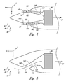
- Fig. 7 is a schematic cross-sectional view comparing a conventional pre-cooler inlet duct 110 (illustrated in dashed lines) to a pre-cooler inlet duct 100 according to the present disclosure that includes an active flow-control device 150 (illustrated in solid lines).
- Pre-cooler inlet ducts 100 according to the present disclosure that include active flow-control devices 150 may provide improved performance over conventional pre-cooler inlet ducts 110 that do not include active flow-control devices 150.
- a boundary layer fluid flow 82 within boundary layer 80 that is adjacent a flow-directing surface 140 of pre-cooler inlet duct 100 may define the performance of pre-cooler inlet duct 100.
- a boundary layer fluid flow within a boundary layer that is attached to a conventional flow-directing surface 180 of conventional pre-cooler inlet duct 110 also may define the performance of conventional pre-cooler inlet duct 110.
- pre-cooler inlet duct 100 may permit pre-cooler inlet duct 100 to have a comparable, or even greater, performance despite having a shorter length 102 than a conventional length 112 of conventional pre-cooler inlet duct 110 and/or despite defining a smaller radius of curvature 104 when compared to a conventional radius of curvature 114 of conventional pre-cooler inlet duct 110.
- the lengths may be defined relative to a starting point 101 at which a profile of flow-directing surface 140 and/or conventional flow-directing surface 180 changes in order to direct and/or bend boundary layer fluid flow 82.
- the radii of curvature may approximate and/or be a radius of curvature traveled by at least a portion of boundary layer fluid flow 82 as boundary layer fluid flow 82 flows around flow-directing surface 140 and/or conventional flow-directing surface 180, respectively.
- length 102 may be less than 90%, less than 80%, less than 70%, less than 60%, less than 50%, less than 40%, less than 30%, and/or less than 20% of conventional length 112.
- radius of curvature 104 may be less than 90%, less than 80%, less than 70%, less than 60%, less than 50%, less than 40%, less than 30%, and/or less than 20% of conventional radius of curvature 114.
- Decreasing length 102 and/or radius of curvature 104 relative to conventional length 112 and/or conventional radius of curvature 114 may provide performance benefits within jet engines 40 that include pre-cooling assemblies 60 and/or pre-cooler inlet ducts 100 according to the present disclosure.
- decreasing length 102 and/or radius of curvature 104 may permit jet engines 40 according to the present disclosure to exhibit less weight and/or a smaller overall outer size when compared to comparable conventional jet engines due to the smaller length 102 and/or radius of curvature 104 of pre-cooler inlet duct 100. This may decrease nacelle friction loss with jet engines 40, increasing fuel economy. Additionally or alternatively, this also may provide for increased flexibility regarding location(s) where jet engines 40 may be mounted on aircraft 20.
- Fig. 8 is a flowchart depicting methods 200, according to the present disclosure, of resisting boundary layer separation from a pre-cooler inlet duct.
- Methods 200 include flowing a pre-cooler air stream through a pre-cooler inlet duct at 210 and modifying a boundary layer with an active flow-control device at 220.
- Flowing the pre-cooler air stream through the pre-cooler inlet duct at 210 may include flowing across a flow-directing surface of the pre-cooler inlet duct and through the pre-cooler inlet duct.
- the flowing at 210 may include generating the boundary layer, which may include a boundary layer fluid flow, adjacent the flow-directing surface.
- the flow-directing surface may define a radius of curvature and/or a length, and the flowing at 210 may include flowing the boundary layer (or the boundary layer fluid flow) along the radius of curvature and/or along the length.
- the boundary layer fluid flow may define a threshold performance, and the radius of curvature may be less than a conventional radius of curvature of a conventional flow-directing surface that produces a comparable threshold performance but that does not utilize the modifying at 220.
- the length may be less than a conventional length of the conventional flow-directing surface that produces the comparable threshold performance but that does not utilize the modifying at 220. Examples of relationships between the radius of curvature and the conventional radius of curvature and/or between the length and the conventional length are disclosed herein.
- Modifying the boundary layer at 220 may include modifying to resist separation of the boundary layer from the flow-directing surface of the pre-cooler inlet duct. This may include modifying any suitable characteristic, or flow characteristic, of the boundary layer and/or of the boundary layer fluid flow to decrease a potential for separation of the boundary layer from the flow-directing surface, such as under expected and/or nominal operating conditions of a jet engine that includes the pre-cooler inlet duct.
- the modifying at 220 may include modifying to resist separation of the boundary layer from the flow-directing surface when an average flow speed of the pre-cooler air stream is at least 100 meters/second (m/s), at least 125 m/s, at least 150 m/s, at least 175 m/s, at least 200 m/s, at least 225 m/s, at least 250 m/s, at least 275 m/s, and/or at least 300 m/s.
- the modifying also may include modifying to resist separation of the boundary layer from the flow-directing surface when the average speed of the pre-cooler air stream is less than 350 m/s, less than 325 m/s, less than 300 m/s, less than 275 m/s, less than 250 m/s, less than 225 m/s, and/or less than 200 m/s.
- the modifying at 220 may be accomplished in any suitable manner.
- the modifying at 220 may include injecting a flow-control fluid stream into the boundary layer at 222, generating a vortex within the boundary layer at 224, and/or removing a suction stream from the boundary layer at 226.
- Injecting the flow-control fluid stream into the boundary layer at 222 may include injecting the flow-control fluid stream through an injection orifice that is defined by, within, and/or along the flow-directing surface.
- the injecting at 222 may include injecting at any suitable flow speed of the flow-control fluid stream, illustrative, non-exclusive examples of which are disclosed herein. Additionally or alternatively, the injecting at 222 also may include injecting such that any suitable pressure differential, illustrative, non-exclusive examples of which are disclosed herein, is developed across the injection orifice.
- the injecting at 222 may include continuously, or at least substantially continuously, injecting the flow-control fluid stream during the flowing at 210.
- the injecting at 222 also may include intermittently injecting the flow-control fluid stream during the flowing at 210.
- the injecting at 222 may include injecting at a first injection angle and/or injecting at a second injection angle.
- injecting at 222 may include injecting at a first injection angle and/or injecting at a second injection angle.
- Illustrative, non-exclusive examples of the first injection angle and the second injection angle are disclosed herein.
- the flow-control fluid stream may be generated in any suitable manner.
- the injecting at 222 may include directing a compressed air stream through the injection orifice.
- the compressed air stream may be generated in any suitable manner, such as by the jet engine and/or via any suitable pump and/or compressor.
- the injecting at 222 may include generating the flow-control fluid stream with a synthetic jet generator.
- the injecting at 222 may include injecting a single flow-control fluid stream or a plurality of flow-control fluid streams.
- the injecting at 222 further may include (systematically and/or periodically) varying which of the plurality of flow-control fluid streams is being injected into the boundary layer at a given point in time.
- the plurality of flow-control fluid streams may be injected in a spaced-apart manner across the flow-directing surface. Illustrative, non-exclusive examples of a spacing among the plurality of flow-control fluid streams and/or of a number of flow-control fluid streams (and/or corresponding injection orifices) in the plurality of flow-control fluid streams are disclosed herein.
- Generating the vortex within the boundary layer at 224 may include generating the vortex in any suitable manner.
- the generating at 224 may include generating with a vortex generator.
- Removing the suction stream from the boundary layer at 226 may include removing the suction fluid stream from the boundary layer in any suitable manner.
- the removing at 226 may include generating a vacuum within a suction assembly to remove the suction stream from the boundary layer.
- the terms “adapted” and “configured” mean that the element, component, or other subject matter is designed and/or intended to perform a given function. Thus, the use of the terms “adapted” and “configured” should not be construed to mean that a given element, component, or other subject matter is simply “capable of” performing a given function but that the element, component, and/or other subject matter is specifically selected, created, implemented, utilized, programmed, and/or designed for the purpose of performing the function. It is also within the scope of the present disclosure that elements, components, and/or other recited subject matter that is recited as being adapted to perform a particular function may additionally or alternatively be described as being configured to perform that function, and vice versa. Similarly, subject matter that is recited as being configured to perform a particular function may additionally or alternatively be described as being operative to perform that function.
Landscapes
- Engineering & Computer Science (AREA)
- Chemical & Material Sciences (AREA)
- Combustion & Propulsion (AREA)
- Mechanical Engineering (AREA)
- General Engineering & Computer Science (AREA)
- Aviation & Aerospace Engineering (AREA)
- Physics & Mathematics (AREA)
- Fluid Mechanics (AREA)
- Structures Of Non-Positive Displacement Pumps (AREA)
- Jet Pumps And Other Pumps (AREA)
Abstract
Description
- The present disclosure relates to pre-cooler inlet ducts for nacelles of jet engines, and more particularly to pre-cooler inlet ducts that utilize active flow-control to interact with, modify, and/or energize a boundary layer fluid flow within a boundary layer adjacent to the pre-cooler inlet duct, and to systems and methods including the pre-cooler inlet duct.
- Nacelles for jet engines may include a pre-cooler inlet duct that may direct a pre-cooler air stream onto a heat exchanger assembly to cool engine bleed air prior to it being utilized by the jet engine and/or by another component of an aircraft that includes the jet engine. The pre-cooler inlet duct may be present within the nacelle and may be located to receive a portion of a compressed air stream that may be pressurized by a compressor of the jet engine.
- Because the pre-cooler inlet is located within the nacelle, a size of the pre-cooler inlet may be restricted by a size of the nacelle. Conversely, a given size pre-cooler inlet may dictate a needed size for a nacelle that may contain the pre-cooler inlet. In addition, a desired flow rate of the pre-cooler air stream also may dictate a needed size for the pre-cooler inlet duct.
- Under certain conditions, it may be desirable to increase the flow rate of the pre-cooler air stream without increasing the size of the pre-cooler inlet duct. Additionally or alternatively, it also may be desirable to decrease the size of the pre-cooler inlet duct, such as to permit the pre-cooler inlet duct to be placed within a smaller nacelle and/or to decrease a portion of the interior of the nacelle that is utilized by the pre-cooler inlet duct, without decreasing the flow rate of the pre-cooler air stream.
- Historically, traditional aerodynamic principles have been utilized to design the size and/or shape of the pre-cooler inlet duct. However, these traditional aerodynamic principles may limit the size and/or shape of the pre-cooler inlet, thereby restricting increases in the flow rate of the pre-cooler air stream and/or decreases in the size of the nacelle. It is with such considerations in mind that examples according to the present disclosure are described in further detail below.
- Pre-cooler inlet ducts that utilize active flow-control and systems and methods including the same are disclosed herein. The systems include a pre-cooler inlet duct for a jet engine that is configured to receive a pre-cooler air stream and to direct the pre-cooler air stream into a heat exchanger. The pre-cooler inlet duct includes a flow-directing surface, which defines at least a portion of the pre-cooler inlet duct, and an active flow-control device. The active flow-control device is located to modify a boundary layer fluid flow within a boundary layer adjacent the flow-directing surface, such as to resist separation of the boundary layer from the flow-directing surface when the pre-cooler air stream flows through the pre-cooler inlet duct. The active flow-control device may modify the boundary layer in any suitable manner, such as by interacting with and/or energizing the boundary layer, to resist separation of the boundary layer from the flow-directing surface.
- In some embodiments, a radius of curvature of the flow-directing surface is less than a radius of curvature of a conventional flow-directing surface that does not include the active flow-control device. In some embodiments, a length of the flow-directing surface is less than a length of the conventional flow-directing surface.
- In some embodiments, the active flow-control device is configured to inject a flow-control fluid stream into the boundary layer through an injection orifice. In some embodiments, the injection orifice forms a portion of a sweeping jet. In some embodiments, the active flow-control device is configured to continuously inject the flow-control fluid stream. In some embodiments, the active flow-control device is configured to intermittently inject the flow-control fluid stream. In some embodiments, the active flow-control device is configured to inject a plurality of flow-control fluid streams. In some embodiments, the active flow-control device is configured to vary which of the plurality of flow-control fluid streams is being injected at a given point in time.
- In some embodiments, the active flow-control device includes a vortex generator configured to generate a vortex within the boundary layer. In some embodiments, the active flow-control device includes a suction assembly configured to remove a suction stream from the boundary layer.
- In some embodiments, the pre-cooler inlet duct forms a portion of a nacelle for a jet engine. In some embodiments, the nacelle forms a portion of an aircraft.
- The methods include methods of resisting boundary layer separation in the pre-cooler inlet duct. The methods include flowing the pre-cooler air stream across the flow-directing surface to generate a boundary layer adjacent the flow-directing surface. The methods further include modifying the boundary layer with the active flow-control device to resist separation of the boundary layer from the flow-directing surface.
-
-
Fig. 1 is a schematic representation of examples of an aircraft that may include a jet engine that may include a pre-cooler inlet duct according to the present disclosure. -
Fig. 2 is a schematic partially fragmentary side view illustrating examples of a jet engine that may include a pre-cooler inlet duct according to the present disclosure. -
Fig. 3 is a schematic front view illustrating examples of a jet engine that may include a pre-cooler inlet duct according to the present disclosure. -
Fig. 4 is a schematic cross-sectional view illustrating examples of a pre-cooler inlet duct according to the present disclosure. -
Fig. 5 is a schematic cross-sectional view illustrating examples of a pre-cooler inlet duct according to the present disclosure. -
Fig. 6 is a schematic cross-sectional view comparing a conventional flow-directing surface to a flow-directing surface according to the present disclosure. -
Fig. 7 is a schematic cross-sectional view comparing two flow-directing surfaces according to the present disclosure. -
Fig. 8 is a flowchart depicting methods, according to the present disclosure, of resisting boundary layer separation from a pre-cooler inlet duct. -
Figs. 1-8 provide illustrative, non-exclusive examples of pre-coolerinlet ducts 100 that include active flow-control devices 150 according to the present disclosure, ofnacelles 54 forjet engines 40 that include pre-coolerinlet ducts 100, ofaircraft 20 that includejet engines 40, and/or of methods of operating the same. Elements that serve a similar, or at least substantially similar, purpose are labeled with like numbers in each ofFigs. 1-8 , and these elements may not be discussed in detail herein with reference to each ofFigs. 1-8 . Similarly, all elements may not be labeled in each ofFigs. 1-8 , but reference numerals associated therewith may be utilized herein for consistency. Elements, components, and/or features that are discussed herein with reference to one or more ofFigs. 1-8 may be included in and/or utilized with any ofFigs. 1-8 without departing from the scope of the present disclosure. - In general, elements that are likely to be included in a given (i.e., a particular) embodiment are illustrated in solid lines, while elements that are optional to a given embodiment are illustrated in dashed lines. However, elements that are shown in solid lines are not essential to all embodiments, and an element shown in solid lines may be omitted from a given embodiment without departing from the scope of the present disclosure.
-
Fig. 1 is a schematic representation of an illustrative, non-exclusive example of anaircraft 20 that may include ajet engine 40 that includes apre-cooling assembly 60 with apre-cooler inlet duct 100 according to the present disclosure, whileFigs. 2-3 are more detailed but still illustrative, non-exclusive examples of ajet engine 40 that includes apre-cooling assembly 60 with apre-cooler inlet duct 100 according to the present disclosure. More specifically,Fig. 2 is a schematic partially fragmentary side view ofjet engines 40, whileFig. 3 is a schematic front view ofjet engines 40. - As illustrated in
Fig. 1 ,aircraft 20 includes anairframe 30, which is operatively attached to and/or configured to support one ormore jet engines 40. As further illustrated inFig. 1 ,jet engines 40 may include anacelle 54 that may be sized and/or shaped to define, contain, and/or house a variety of components ofjet engine 40. As examples,jet engines 40 may include aninlet 42, which is configured to receive anair stream 43, and acompressor 44, which is configured to compress (or increase a pressure of)air stream 43 to generate acompressed air stream 45.Jet engines 40 also may include aburner 46, which is configured to combust a fuel stream with aportion 53 ofcompressed air stream 45 to generate a combustion stream, and aturbine 48, which is configured to be powered by the combustion stream and topower compressor 44. - As illustrated in
Figs. 1-2 ,jet engines 40 further may include anozzle 50, which is configured to permit the combustion stream to be expelled from (or to exit)jet engine 40. As illustrated most clearly inFig. 2 ,jet engines 40 may define acentral duct 52, which is configured to receiveportion 53 ofcompressed air stream 45 fromcompressor 44, and pre-coolerinlet duct 100, which is configured to receive another portion ofcompressed air stream 45, which is referred to herein as apre-cooler air stream 65. Pre-coolerinlet duct 100 may form a portion of pre-coolingassembly 60 and may provide and/or direct pre-coolerair stream 65 to and/or toward aheat exchanger 66.Heat exchanger 66 may be configured to exchange thermal energy withpre-cooler air stream 65 to generate a heat-exchangedair stream 67. Heat-exchangedair stream 67 may be provided to another component ofjet engine 40 and/or ofaircraft 20. - As discussed in more detail herein, and when pre-cooler
air stream 65 is flowing throughpre-cooler inlet duct 100, an active flow-control device 150 may be configured, utilized, and/or operated to resist separation of aboundary layer 80, which includes a boundarylayer fluid flow 82, from a flow-directingsurface 140 ofpre-cooler inlet duct 100. As an illustrative, non-exclusive example, active flow-control device 150 may be configured to modify boundarylayer fluid flow 82, thereby changing one or more characteristics of boundarylayer fluid flow 82 and permitting boundarylayer fluid flow 82 to flow across flow-directingsurface 140 without separation therefrom. - In general, pre-cooling
assemblies 60 and/or pre-coolerinlet ducts 100 according to the present disclosure that include active flow-control device 150 may be configured to maintain and/or retainboundary layer 80 attached to flow-directingsurface 140 over a wide range of average pre-cooler air stream speeds of pre-coolerair stream 65. As illustrative, non-exclusive examples, pre-coolingassemblies 60 and/or pre-coolerinlet ducts 100 according to the present disclosure may maintainboundary layer 80 attached to pre-coolerinlet duct 100 when the average pre-cooler air stream speed is at least 50 meters/second (m/s), at least 75 m/s, at least 100 m/s, at least 125 m/s, at least 150 m/s, at least 175 m/s, at least 200 m/s, at least 225 m/s, at least 250 m/s, at least 275 m/s, and/or at least 300 m/s. Additionally or alternatively,pre-cooling assemblies 60 also may maintainboundary layer 80 attached to flow-directingsurface 140 when the average pre-cooler air stream speed is less than 350 m/s, less than 325 m/s, less than 300 m/s, less than 275 m/s, less than 250 m/s, less than 225 m/s, and/or less than 200 m/s. - Active flow-
control device 150 may include and/or utilize any suitable active flow-control technology. As an illustrative, non-exclusive example, and as discussed in more detail herein, active flow-control device 150 may be configured to inject a flow-control fluid stream intoboundary layer 80. As another illustrative, non-exclusive example, active flow-control device 150 may include a vortex generator that is configured to generate a vortex withinboundary layer 80. As yet another illustrative, non-exclusive example, active flow-control device 150 may be configured to remove a suction stream fromboundary layer 80. - It is within the scope of the present disclosure that active flow-
control device 150 may supply the flow-control fluid stream, may generate the vortex, and/or may remove the suction stream in any suitable manner and/or utilizing any suitable equipment. As illustrative, non-exclusive examples, active flow-control device 150 may include one or more of a piezoelectric actuator, a shape memory alloy actuator, a diaphragm, a pump, a compressor, and/or a fan. - As illustrated in
Fig. 3 , pre-coolingassembly 60 andpre-cooler inlet duct 100 thereof may be located within aninternal volume 56 ofnacelle 54. Thus, a size, shape, and/or volume ofpre-cooling assembly 60 and/or ofpre-cooler inlet duct 100 may be constrained by a target, desired, and/or specified size ofnacelle 54 and/or by a size and/or geometry of the other components that may be present withininternal volume 56. - As discussed, it may be desirable to increase a flow rate of pre-cooler air stream 65 (as illustrated in
Fig. 2 ) intopre-cooler inlet duct 100 without increasing the size ofnacelle 54, andpre-cooling assemblies 60 with bifurcated pre-cooler inlets have been utilized to provide for this increase in flow rate ofpre-cooler air stream 65. Such a bifurcated pre-cooler inlet includes twopre-cooler inlet ducts 100. One of thesepre-cooler inlet ducts 100 is illustrated in solid lines inFig. 3 , while the otherpre-cooler inlet duct 100 is illustrated in dashed lines to indicate that the second pre-cooler inlet duct may be optional. While bifurcated pre-cooler inlets may provide for a measurable increase in the flow rate ofpre-cooler air stream 65, it may be desirable to further increase the flow rate ofpre-cooler air stream 65 and/or to utilize pre-cooling assemblies that include only a single pre-cooler inlet duct. This may be accomplished by locating one or more active flow-control devices 150 on one or more flow-directingsurfaces 140 ofpre-cooling assembly 60, and is discussed in more detail herein. -
Figs. 4-5 provide schematic cross-sectional views of illustrative, non-exclusive examples ofpre-cooler inlet ducts 100 that may be utilized inpre-cooling assemblies 60 according to the present disclosure. The schematic cross-sectional views ofFigs. 4-5 may be taken along line A-A ofFig. 3 . - In
Figs. 4-5 ,pre-cooling assemblies 60 include one or morepre-cooler inlet ducts 100.Pre-cooler inlet duct 100 may be at least partially defined by one or more flow-directingsurfaces 140 and may be configured to direct apre-cooler air stream 65 toward and/or into contact with aheat exchanger 66.Heat exchanger 66 receivespre-cooler air stream 65 and produces heat-exchangedair stream 67 therefrom. InFig. 4 , pre-coolingassembly 60 includes a bifurcated pre-cooler inlet that includes twopre-cooler inlet ducts 100. In contrast, pre-coolingassembly 60 ofFig. 5 includes a singlepre-cooler inlet duct 100. - In
Figs. 4-5 , one or more flow-directingsurface 140 may include and/or utilize one or more active flow-control devices 150. Active flow-control devices 150 may be configured to resist separation of a boundarylayer fluid flow 82 of aboundary layer 80 from respective flow-directingsurfaces 140, as illustrated inFig. 6 and discussed in more detail herein. As also discussed in more detail herein, the presence of active flow-control devices 150 may permit a decrease in one or more dimensions ofpre-cooler inlet ducts 100 and/or ofpre-cooling assembly 60 and/or may permitpre-cooling assemblies 60 to utilize a single pre-cooler inlet duct 100 (as illustrated inFig. 5 ) as opposed to a bifurcated pre-cooler inlet that includes two pre-cooler inlet ducts 100 (as illustrated inFig. 4 ) while maintaining a target, or desired, flow rate forpre-cooler air stream 65 and/or for heat-exchangedair stream 67. In this manner, a size of a pre-cooler inlet duct 10 and/orpre-cooling assembly 60 may be reduced without reduction in performance of thepre-cooling assembly 60. - Active flow-
control devices 150 are illustrated in dashed lines inFigs. 4-5 to indicate that active flow-control devices 150 may be located and/or present on any suitable flow-directingsurface 140 ofpre-cooler inlet ducts 100 according to the present disclosure. As an example, active flow-control devices 150 may be located on multiple (i.e., two or more) flow-directingsurfaces 140 that define a given pre-cooler inlet duct 100 (e.g. opposing surfaces 140 of upper and/or lowerpre-cooler inlet duct 100 inFig. 4 or opposingsurfaces 140 of the singlepre-cooler inlet duct 100 inFig. 5 ). As another example, active flow-control devices 150 may be located on one flow-directingsurface 140 that defines the givenpre-cooler inlet duct 100 but not on another flow-directingsurface 140 that defines the givenpre-cooler inlet duct 100. As yet another example, flow-control devices 150 may be located on portion(s) of flow-directingsurfaces 140 where a large change in direction of boundary layer fluid flow 82 (illustrated inFig. 6 ) is present. This may include portion(s) of flow-directingsurfaces 140 that have and/or define a (relatively) smaller radius ofcurvature 104, as discussed herein with reference toFigs. 6-7 . -
Fig. 6 is a schematic cross-sectional view of a portion of apre-cooling assembly 60 including apre-cooler inlet duct 100 that is at least partially defined by a flow-directingsurface 140 according to the present disclosure. As illustrated inFig. 6 , flow-directingsurface 140 includes one or more active flow-control devices 150 according to the present disclosure. As discussed, active flow-control devices 150 may be configured to interact with, modify, and/or energize a boundarylayer fluid flow 82 that is present within aboundary layer 80 of apre-cooler air stream 65 that is flowing past flow-directingsurface 140 to resist separation ofboundary layer 80 from flow-directingsurface 140. This may be accomplished in any suitable manner. - As an illustrative, non-exclusive example, active flow-
control device 150 maybe configured to inject one or more flow-control fluid streams 152 intoboundary layer 80 through aninjection orifice 154 that may be defined by, within, and/or on flow-directingsurface 140. Flow-control fluid stream 152 may be injected intoboundary layer 80 in any suitable manner. As an illustrative, non-exclusive example, flow-control fluid stream 152 may be injected at a flow speed, or average flow speed, of at least 100 meters/second (m/s), at least 125 m/s, at least 150 m/s, at least 175 m/s, at least 200 m/s, at least 225 m/s, at least 250 m/s, at least 275 m/s, at least 300 m/s, at least 350 m/s, at least 400 m/s, at least 450 m/s, or at least 500 m/s. As another illustrative, non-exclusive example, flow-control fluid stream 152 may be injected at a flow speed, or average flow speed, of less than 700 m/s, less than 650 m/s, less than 600 m/s, less than 550 m/s, less than 500 m/s, less than 450 m/s, less than 400 m/s, less than 350 m/s, less than 325 m/s, less than 300 m/s, less than 275 m/s, less than 250 m/s, less than 225 m/s, and/or less than 200 m/s. As yet another illustrative, non-exclusive example, flow-control fluid stream 152 may be injected throughinjection orifice 154 such that a pressure differential across the injection orifice is at least 1 kilopascal (kPa), at least 5 kPa, at least 10 kPa, at least 15 kPa, at least 20 kPa, at least 25 kPa, at least 30 kPa, at least 35 kPa, at least 40 kPa, at least 50 kPa, at least 75 kPa, at least 100 kPa, at least 150 kPa, at least 200 kPa, at least 300 kPa, at least 400 kPa, at least 500 kPa, at least 600 kPa, and/or at least 700 kPa. - It is within the scope of the present disclosure that active flow-
control device 150 may be configured to continuously, or at least substantially continuously, inject flow-control fluid stream 152 intoboundary layer 80 whenpre-cooler air stream 65 is flowing past flow-directingsurface 140. Additionally or alternatively, it is also within the scope of the present disclosure that active flow-control device 150 may be configured to intermittently, selectively, and/or periodically inject flow-control fluid stream 152 intoboundary layer 80 whenpre-cooler air stream 65 is flowing past flow-directingsurface 140. - Flow-
control fluid stream 152 may be injected intoboundary layer 80 at any suitable location. As an illustrative, non-exclusive example, active flow-control device 150 may be configured to inject a plurality of flow-control fluid streams 152 intoboundary layer 80. This may include injecting the plurality of flow-control fluid streams in a spaced-apart manner around a curvature, or radius of curvature, 104 of flow-directingsurface 140, as illustrated inFig. 6 . Additionally or alternatively, this also may include injecting the plurality of flow-control fluid streams in a spaced-apart manner along a length of flow-directing surface 140 (i.e., in a spaced-apart manner along the Z-axis ofFig. 6 ). - As yet another illustrative, non-exclusive example, flow-
control fluid stream 152 may be injected behind, downstream of, and/or on a lee side of astep 130 on a surface of flow-directingsurface 140. Step 130 may include and/or be any suitable discontinuity and/or change in profile of flow-directingsurface 140 and also may be referred to herein as adiscontinuity 130. - Flow-
control fluid stream 152 may be generated in any suitable manner. As an illustrative, non-exclusive example, flow-control fluid stream 152 may include and/or be a portion ofcompressed air stream 45 that is generated byjet engine 40 and/or bycompressor 44 thereof (as illustrated inFigs. 1-2 ). Additionally or alternatively, flow-control fluid stream 152 may include and/or be a synthetic jet that is generated by asynthetic jet generator 158. - As another illustrative, non-exclusive example, active flow-
control device 150 may include asuction assembly 160 that is configured to withdraw asuction stream 161 fromboundary layer 80. As yet another illustrative, non-exclusive example, active flow-control device 150 may include avortex generator 156 that is configured to generate avortex 157 withinboundary layer 80.Vortex generator 156 may include any suitable active and/orpassive vortex generator 156 that is configured to generatevortex 157 in any suitable manner. As illustrative, non-exclusive examples,vortex generator 156 may include a physical obstruction and/or a vortex generator jet actuator. - When active flow-
control device 150 injects flow-control fluid stream 152 intoboundary layer 80, flow-control fluid stream 152 may be injected with any suitable orientation and/or at any suitable angle, or injection angle. As an illustrative, non-exclusive example, flow-control fluid stream 152 may be injected intoboundary layer 80 at afirst injection angle 170.First injection angle 170 may be measured in a first plane that is parallel to a surfacenormal direction 168 of flow-directingsurface 140, and it is within the scope of the present disclosure thatfirst injection angle 170 may include and/or be any suitable angle. The first plane also may be perpendicular to a length of flow-directing surface 140 (i.e., the Z-direction inFig. 6 ). - In addition, flow-
control fluid stream 152 also may be injected intoboundary layer 80 at asecond injection angle 174.Second injection angle 174 may be measured in a second plane that is parallel to surfacenormal direction 168 and perpendicular to the first plane, and it is within the scope of the present disclosure thatsecond injection angle 174 may include any suitable angle. The second plane also may be parallel to the length of flow-directingsurface 140. - Illustrative, non-exclusive examples of
first injection angle 170 and/orsecond injection angle 174 include angles of at least 0 degrees, at least 5 degrees, at least 10 degrees, at least 15 degrees, at least 20 degrees, at least 30 degrees, at least 40 degrees, at least 50 degrees, at least 60 degrees, at least 70 degrees, at least 80 degrees, at least 90 degrees, at least 100 degrees, at least 110 degrees, at least 120 degrees, at least 130 degrees, at least 140 degrees, at least 150 degrees, at least 160 degrees, and/or at least 170 degrees. As additional illustrative, non-exclusive examples,first injection angle 170 and/orsecond injection angle 174 may include angles of less than 180 degrees, less than 170 degrees, less than 160 degrees, less than 150 degrees, less than 140 degrees, less than 130 degrees, less than 120 degrees, less than 110 degrees, less than 100 degrees, less than 90 degrees, less than 80 degrees, less than 70 degrees, less than 60 degrees, less than 50 degrees, less than 40 degrees, less than 30 degrees, less than 20 degrees, less than 15 degrees, less than 10 degrees, and/or less than 5 degrees. - It is within the scope of the present disclosure that
first injection angle 170 and/orsecond injection angle 174 may be a variable angle that varies between any of the above-listed lower limits and any of the above-listed upper limits. Under these conditions, flow-control fluid stream 152 may be generated by a sweeping jet that systematically and/or periodically varies the first injection angle and/or the second injection angle. - The plurality of active flow-control devices may include any suitable number of active flow-control devices. As illustrative, non-exclusive examples, flow-directing
surface 140 may include at least 4, at least 8, at least 9, at least 12, at least 18, at least 24, at least 36, at least 72, at least 90, at least 120, at least 180, at least 270, and/or at least 360 active flow-control devices 150 and/orinjection orifices 154, or may be configured to inject a corresponding number of flow-control fluid streams 152. As additional illustrative, non-exclusive examples, flow-directingsurface 140 also may include fewer than 36, fewer than 72, fewer than 90, fewer than 120, fewer than 180, fewer than 270, fewer than 360, and/or fewer than 720 active flow-control devices 150 and/orinjection orifices 154, or may be configured to inject a corresponding number of flow-control fluid streams 152. - When flow-directing
surface 140 includes the plurality of active flow-control devices 150 and/or is configured to inject the plurality of flow-control fluid streams 152, the plurality of flow-control fluid streams 152 may be injected in any suitable manner. As an illustrative, non-exclusive example, each of the plurality of flow-control fluid streams may be injected continuously whenpre-cooler air stream 65 is flowing past flow-directingsurface 140 and/or thoroughpre-cooler inlet duct 100. As another illustrative, non-exclusive example, one or more of the flow-control fluid streams 152 may be injected intermittently. This may include (systematically) varying which of the plurality of flow-control fluid streams 152 is being injected at a given point in time. - When active flow-
control device 150 is configured to inject the plurality of flow-control fluid streams 152, the plurality of flow-control fluid streams may be injected through the plurality ofinjection orifices 154, which may be defined by flow-directingsurface 140. It is within the scope of the present disclosure that the plurality ofinjection orifices 154 may include any suitable cross-sectional shape, including circular, elongate, slotted, square, arcuate, and/or rectangular cross-sectional shapes, and that at least a portion of the plurality ofinjection orifices 154 may have a different cross-sectional shape and/or size relative to a remainder of the plurality ofinjection orifices 154. It is also within the scope of the present disclosure that active flow-control device 150 may include a continuous, or at least substantially continuous, slot that may be configured to inject one or more flow-control fluid streams along and/or across flow-directingsurface 140. -
Fig. 7 is a schematic cross-sectional view comparing a conventional pre-cooler inlet duct 110 (illustrated in dashed lines) to apre-cooler inlet duct 100 according to the present disclosure that includes an active flow-control device 150 (illustrated in solid lines).Pre-cooler inlet ducts 100 according to the present disclosure that include active flow-control devices 150 may provide improved performance over conventionalpre-cooler inlet ducts 110 that do not include active flow-control devices 150. - As an illustrative, non-exclusive example, a boundary
layer fluid flow 82 withinboundary layer 80 that is adjacent a flow-directingsurface 140 ofpre-cooler inlet duct 100 may define the performance ofpre-cooler inlet duct 100. Similarly, a boundary layer fluid flow within a boundary layer that is attached to a conventional flow-directingsurface 180 of conventionalpre-cooler inlet duct 110 also may define the performance of conventionalpre-cooler inlet duct 110. The presence of active flow-control devices 150 inpre-cooler inlet duct 100 according to the present disclosure, may permitpre-cooler inlet duct 100 to have a comparable, or even greater, performance despite having ashorter length 102 than aconventional length 112 of conventionalpre-cooler inlet duct 110 and/or despite defining a smaller radius ofcurvature 104 when compared to a conventional radius ofcurvature 114 of conventionalpre-cooler inlet duct 110. The lengths may be defined relative to astarting point 101 at which a profile of flow-directingsurface 140 and/or conventional flow-directingsurface 180 changes in order to direct and/or bend boundarylayer fluid flow 82. Similarly, the radii of curvature may approximate and/or be a radius of curvature traveled by at least a portion of boundarylayer fluid flow 82 as boundarylayer fluid flow 82 flows around flow-directingsurface 140 and/or conventional flow-directingsurface 180, respectively. - As illustrative, non-exclusive examples,
length 102 may be less than 90%, less than 80%, less than 70%, less than 60%, less than 50%, less than 40%, less than 30%, and/or less than 20% ofconventional length 112. Additionally or alternatively, radius ofcurvature 104 may be less than 90%, less than 80%, less than 70%, less than 60%, less than 50%, less than 40%, less than 30%, and/or less than 20% of conventional radius ofcurvature 114. - Decreasing
length 102 and/or radius ofcurvature 104 relative toconventional length 112 and/or conventional radius ofcurvature 114 may provide performance benefits withinjet engines 40 that includepre-cooling assemblies 60 and/orpre-cooler inlet ducts 100 according to the present disclosure. As an illustrative, non-exclusive example, decreasinglength 102 and/or radius ofcurvature 104 may permitjet engines 40 according to the present disclosure to exhibit less weight and/or a smaller overall outer size when compared to comparable conventional jet engines due to thesmaller length 102 and/or radius ofcurvature 104 ofpre-cooler inlet duct 100. This may decrease nacelle friction loss withjet engines 40, increasing fuel economy. Additionally or alternatively, this also may provide for increased flexibility regarding location(s) wherejet engines 40 may be mounted onaircraft 20. -
Fig. 8 is aflowchart depicting methods 200, according to the present disclosure, of resisting boundary layer separation from a pre-cooler inlet duct.Methods 200 include flowing a pre-cooler air stream through a pre-cooler inlet duct at 210 and modifying a boundary layer with an active flow-control device at 220. - Flowing the pre-cooler air stream through the pre-cooler inlet duct at 210 may include flowing across a flow-directing surface of the pre-cooler inlet duct and through the pre-cooler inlet duct. The flowing at 210 may include generating the boundary layer, which may include a boundary layer fluid flow, adjacent the flow-directing surface.
- The flow-directing surface may define a radius of curvature and/or a length, and the flowing at 210 may include flowing the boundary layer (or the boundary layer fluid flow) along the radius of curvature and/or along the length. As discussed, the boundary layer fluid flow may define a threshold performance, and the radius of curvature may be less than a conventional radius of curvature of a conventional flow-directing surface that produces a comparable threshold performance but that does not utilize the modifying at 220. Additionally or alternatively, the length may be less than a conventional length of the conventional flow-directing surface that produces the comparable threshold performance but that does not utilize the modifying at 220. Examples of relationships between the radius of curvature and the conventional radius of curvature and/or between the length and the conventional length are disclosed herein.
- Modifying the boundary layer at 220 may include modifying to resist separation of the boundary layer from the flow-directing surface of the pre-cooler inlet duct. This may include modifying any suitable characteristic, or flow characteristic, of the boundary layer and/or of the boundary layer fluid flow to decrease a potential for separation of the boundary layer from the flow-directing surface, such as under expected and/or nominal operating conditions of a jet engine that includes the pre-cooler inlet duct. As an illustrative, non-exclusive example, the modifying at 220 may include modifying to resist separation of the boundary layer from the flow-directing surface when an average flow speed of the pre-cooler air stream is at least 100 meters/second (m/s), at least 125 m/s, at least 150 m/s, at least 175 m/s, at least 200 m/s, at least 225 m/s, at least 250 m/s, at least 275 m/s, and/or at least 300 m/s. Additionally or alternatively, the modifying also may include modifying to resist separation of the boundary layer from the flow-directing surface when the average speed of the pre-cooler air stream is less than 350 m/s, less than 325 m/s, less than 300 m/s, less than 275 m/s, less than 250 m/s, less than 225 m/s, and/or less than 200 m/s.
- The modifying at 220 may be accomplished in any suitable manner. As illustrative, non-exclusive examples, the modifying at 220 may include injecting a flow-control fluid stream into the boundary layer at 222, generating a vortex within the boundary layer at 224, and/or removing a suction stream from the boundary layer at 226.
- Injecting the flow-control fluid stream into the boundary layer at 222 may include injecting the flow-control fluid stream through an injection orifice that is defined by, within, and/or along the flow-directing surface. The injecting at 222 may include injecting at any suitable flow speed of the flow-control fluid stream, illustrative, non-exclusive examples of which are disclosed herein. Additionally or alternatively, the injecting at 222 also may include injecting such that any suitable pressure differential, illustrative, non-exclusive examples of which are disclosed herein, is developed across the injection orifice.
- The injecting at 222 may include continuously, or at least substantially continuously, injecting the flow-control fluid stream during the flowing at 210. Alternatively, the injecting at 222 also may include intermittently injecting the flow-control fluid stream during the flowing at 210.
- It is within the scope of the present disclosure that the injecting at 222 may include injecting at a first injection angle and/or injecting at a second injection angle. Illustrative, non-exclusive examples of the first injection angle and the second injection angle are disclosed herein.
- The flow-control fluid stream may be generated in any suitable manner. As an illustrative, non-exclusive example, the injecting at 222 may include directing a compressed air stream through the injection orifice. The compressed air stream may be generated in any suitable manner, such as by the jet engine and/or via any suitable pump and/or compressor. As another illustrative, non-exclusive example, the injecting at 222 may include generating the flow-control fluid stream with a synthetic jet generator.
- The injecting at 222 may include injecting a single flow-control fluid stream or a plurality of flow-control fluid streams. When the injecting at 222 includes injecting the plurality of flow-control fluid streams, the injecting at 222 further may include (systematically and/or periodically) varying which of the plurality of flow-control fluid streams is being injected into the boundary layer at a given point in time. Additionally or alternatively, and as discussed, the plurality of flow-control fluid streams may be injected in a spaced-apart manner across the flow-directing surface. Illustrative, non-exclusive examples of a spacing among the plurality of flow-control fluid streams and/or of a number of flow-control fluid streams (and/or corresponding injection orifices) in the plurality of flow-control fluid streams are disclosed herein.
- Generating the vortex within the boundary layer at 224 may include generating the vortex in any suitable manner. As an illustrative, non-exclusive example, the generating at 224 may include generating with a vortex generator.
- Removing the suction stream from the boundary layer at 226 may include removing the suction fluid stream from the boundary layer in any suitable manner. As an illustrative, non-exclusive example, the removing at 226 may include generating a vacuum within a suction assembly to remove the suction stream from the boundary layer.
- Illustrative, non-exclusive examples of inventive subject matter according to the present disclosure are described in the following enumerated paragraphs:
- A1. A pre-cooler inlet duct for a jet engine, wherein the pre-cooler inlet duct is configured to receive a pre-cooler air stream from a compressed air stream that is pressurized by a compressor of a jet engine and to direct the pre-cooler air stream into a heat exchanger, the pre-cooler inlet duct comprising:
- a flow-directing surface that defines at least a portion of the pre-cooler inlet duct and is shaped to direct the pre-cooler air stream into the heat exchanger; and
- an active flow-control device located to modify a boundary layer fluid flow within a boundary layer adjacent the flow-directing surface to resist separation of the boundary layer from the flow-directing surface when the pre-cooler air stream flows through the pre-cooler inlet duct.
- A2. The pre-cooler inlet duct of paragraph A1, wherein the boundary layer fluid flow defines a threshold performance, and further wherein a radius of curvature of the flow-directing surface is less than a conventional radius of curvature of a conventional flow-directing surface of a conventional pre-cooler inlet duct that produces a comparable threshold performance but that does not include the active flow control device.
- A2.1 The pre-cooler inlet duct of paragraph A2, wherein the radius of curvature of the flow-directing surface is less than 90%, less than 80%, less than 70%, less than 60%, less than 50%, or less than 40% of the conventional radius of curvature of the conventional flow-directing surface.
- A3. The pre-cooler inlet duct of any of paragraphs A1-A2.1, wherein the boundary layer defines a/the threshold performance, and further wherein a length of the flow-directing surface is less than a conventional length of a/the conventional flow-directing surface that produces a/the comparable threshold performance but that does not include the active flow-control device.
- A3.1 The pre-cooler inlet duct of paragraph A3, wherein the length of the flow-directing surface is less than 90% less than 80%, less than 70%, less than 60%, less than 50%, or less than 40% of the conventional length of the conventional flow-directing surface.
- A4. The pre-cooler inlet duct of any of paragraphs A1-A3.1, wherein the pre-cooler inlet duct includes the boundary layer.
- A4.1 The pre-cooler inlet duct of any of paragraphs A1-A4, wherein the pre-cooler inlet duct includes the boundary layer fluid flow.
- A5. The pre-cooler inlet duct of any of paragraphs A1-A4.1, wherein the pre-cooler inlet duct includes the pre-cooler air stream.
- A6. The pre-cooler inlet duct of any of paragraphs A1-A5, wherein the active flow-control device is configured to resist separation of the boundary layer from the flow-directing surface when an average pre-cooler air stream flow speed through the pre-cooler inlet duct is at least one of:
- (i) at least 100 meters/second (m/s), at least 125 m/s, at least 150 m/s, at least 175 m/s, at least 200 m/s, at least 225 m/s, at least 250 m/s, at least 275 m/s, or at least 300 m/s; and
- (ii) less than 350 m/s, less than 325 m/s, less than 300 m/s, less than 275 m/s, less than 250 m/s, less than 225 m/s, or less than 200 m/s.
- A7. The pre-cooler inlet duct of any of paragraphs A1-A6, wherein the active flow-control device is configured to inject a flow-control fluid stream into the boundary layer through an injection orifice that is defined by the flow-directing surface.
- A7.1 The pre-cooler inlet duct of paragraph A7, wherein the injection orifice forms a portion of a sweeping jet.
- A7.2 The pre-cooler inlet duct of any of paragraphs A7-A7.1, wherein the pre-cooler inlet duct includes the flow-control fluid stream.
- A7.3 The pre-cooler inlet duct of any of paragraphs A7-A7.2, wherein a flow speed of the flow-control fluid stream through the injection orifice is at least one of:
- (i) at least 100 meters/second (m/s), at least 125 m/s, at least 150 m/s, at least 175 m/s, at least 200 m/s, at least 225 m/s, at least 250 m/s, at least 275 m/s, at least 300 m/s, at least 350 m/s, at least 400 m/s, at least 450 m/s, or at least 500 m/s; and
- (ii) less than 700 m/s, less than 650 m/s, less than 600 m/s, less than 550 m/s, less than 500 m/s, less than 450 m/s, less than 400 m/s, less than 350 m/s, less than 325 m/s, less than 300 m/s, less than 275 m/s, less than 250 m/s, less than 225 m/s, or less than 200 m/s.
- A7.4 The pre-cooler inlet duct of any of paragraphs A7-A7.3, wherein a pressure differential of the flow-control fluid stream across the injection orifice is at least 1 kilopascal (kPa), at least 5 kPa, at least 10 kPa, at least 15 kPa, at least 20 kPa, at least 25 kPa, at least 30 kPa, at least 35 kPa, or at least 40 kPa.
- A7.5 The pre-cooler inlet duct of any of paragraphs A7-A7.4, wherein the active flow-control device is configured to continuously inject the flow-control fluid stream into the boundary layer when the pre-cooler air stream is flowing through the pre-cooler inlet duct.
- A7.6 The pre-cooler inlet duct of any of paragraphs A7-A7.4, wherein the active flow-control device is configured to intermittently inject the flow-control fluid stream into the boundary layer when the pre-cooler air stream is flowing through the pre-cooler inlet duct.
- A7.7 The pre-cooler inlet duct of any of paragraphs A7-A7.6, wherein the injection orifice includes at least one of a circular injection orifice, an elongate injection orifice, a slot, and a rectangular slot.
- A7.8 The pre-cooler inlet duct of any of paragraphs A7-A7.7, wherein the active flow-control device is configured to inject the flow-control fluid stream into the boundary layer at a first injection angle as measured in a first plane that is parallel to a surface normal of the flow-directing surface and a second injection angle as measured in a second plane that is parallel to the surface normal direction and perpendicular to the first plane.
- A7.8.1 The pre-cooler inlet duct of paragraph A7.8, wherein the first injection angle is at least one of:
- (i) at least 0 degrees, at least 5 degrees, at least 10 degrees, at least 15 degrees, at least 20 degrees, at least 30 degrees, at least 40 degrees, at least 50 degrees, at least 60 degrees, at least 70 degrees, at least 80 degrees, at least 90 degrees, at least 100 degrees, at least 110 degrees, at least 120 degrees, at least 130 degrees, at least 140 degrees, at least 150 degrees, at least 160 degrees, or at least 170 degrees;
- (ii) less than 180 degrees, less than 170 degrees, less than 160 degrees, less than 150 degrees, less than 140 degrees, less than 130 degrees, less than 120 degrees, less than 110 degrees, less than 100 degrees, less than 90 degrees, less than 80 degrees, less than 70 degrees, less than 60 degrees, less than 50 degrees, less than 40 degrees, less than 30 degrees, less than 20 degrees, less than 15 degrees, less than 10 degrees, or less than 5 degrees; and
- (iii) a variable first injection angle that varies between any one of (i) and any one of (ii).
- A7.8.2 The pre-cooler inlet duct of any of paragraphs A7.8-A7.8.1, wherein the second injection angle is at least one of:
- (i) at least 0 degrees, at least 5 degrees, at least 10 degrees, at least 15 degrees, at least 20 degrees, at least 30 degrees, at least 40 degrees, at least 50 degrees, at least 60 degrees, at least 70 degrees, at least 80 degrees, at least 90 degrees, at least 100 degrees, at least 110 degrees, at least 120 degrees, at least 130 degrees, at least 140 degrees, at least 150 degrees, at least 160 degrees, or at least 170 degrees;
- (ii) less than 180 degrees, less than 170 degrees, less than 160 degrees, less than 150 degrees, less than 140 degrees, less than 130 degrees, less than 120 degrees, less than 110 degrees, less than 100 degrees, less than 90 degrees, less than 80 degrees, less than 70 degrees, less than 60 degrees, less than 50 degrees, less than 40 degrees, less than 30 degrees, less than 20 degrees, less than 15 degrees, less than 10 degrees, or less than 5 degrees; and
- (iii) a variable second injection angle that varies between any one of (i) and any one of (ii).
- A7.9 The pre-cooler inlet duct of any of paragraphs A7-A7.8.2, wherein the active flow-control device is configured to inject a plurality of flow-control fluid streams into the boundary layer.
- A7.9.1 The pre-cooler inlet duct of paragraph A7.9, wherein the active flow-control device is configured to (systematically) vary which of the plurality of flow-control fluid streams is being injected into the boundary layer at a given point in time.
- A7.9.2 The pre-cooler inlet duct of any of paragraphs A7.9-A7.9.1, wherein the active flow-control device is configured to inject the plurality of flow-control fluid streams into the boundary layer via a plurality of injection orifices that is defined by the flow-directing surface.
- A7.9.2.1 The pre-cooler inlet duct of paragraph A7.9.2, wherein the plurality of injection orifices is spaced-apart on the flow-directing surface.
- A7.9.2.2 The pre-cooler inlet duct of any of paragraphs A7.9.2-A7.9.2.1, wherein the plurality of injection orifices includes at least one of:
- (i) at least 4, at least 8, at least 9, at least 12, at least 18, at least 24, at least 36, at least 72, at least 90, at least 120, at least 180, at least 270, or at least 360 injection orifices; and
- (ii) fewer than 36, fewer than 72, fewer than 90, fewer than 120, fewer than 180, fewer than 270, fewer than 360, or fewer than 720 injection orifices.
- A7.10 The pre-cooler inlet duct of any of paragraphs A7-A7.9.2.2, wherein the flow-control fluid stream comprises a compressed air stream that optionally is generated by the jet engine.
- A7.11 The pre-cooler inlet duct of any of paragraphs A7-A7.10, wherein the flow-control fluid stream comprises a synthetic jet that optionally is generated by a synthetic jet generator.
- A8. The pre-cooler inlet duct of any of paragraphs A1-A7.13, wherein the active flow-control device includes a vortex generator configured to generate a vortex within the boundary layer.
- A9. The pre-cooler inlet duct of any of paragraphs A1-A8, wherein the active flow-control device comprises a suction assembly configured to remove a suction stream from the boundary layer.
- A10. The pre-cooler inlet duct of any of paragraphs A1-A9, wherein the active flow-control device includes at least one of a piezoelectric actuator, a shape memory alloy actuator, a diaphragm, a pump, a compressor, and a fan.
- B1. A nacelle for a jet engine, comprising:
- an inlet configured to receive an air stream; and
- a pre-cooling assembly including the pre-cooler inlet duct of any of paragraphs AL-A10, wherein the pre-cooler inlet duct is fluidly coupled to an inlet of the nacelle.
- B2. The jet engine of paragraph B1, wherein the pre-cooling assembly further includes a heat exchanger that is configured to receive the pre-cooler air stream from the pre-cooler inlet duct.
- C1. An aircraft, comprising:
- an airframe; and
- the jet engine of any of paragraphs B1-B2.
- D1. A method of resisting boundary layer separation from a flow-directing surface of a pre-cooler inlet duct, the method comprising:
- flowing a pre-cooler air stream across the flow-directing surface and through the pre-cooler inlet duct of a jet engine that includes the pre-cooler inlet duct, wherein the flowing includes generating a boundary layer adjacent the flow-directing surface, and further wherein the boundary layer includes a boundary layer fluid flow; and
- modifying the boundary layer fluid flow with an active flow-control device to resist separation of the boundary layer from the flow-directing surface.
- D2. The method of paragraph D1, wherein the boundary layer fluid flow defines a threshold performance, wherein the flow-directing surface defines a radius of curvature, wherein the flowing includes flowing the boundary layer along the radius of curvature, and further wherein the radius of curvature is less than a conventional radius of curvature of a conventional flow-directing surface that produces a comparable threshold performance but that does not utilize the modifying.
- D2.1 The method of paragraph D2, wherein the radius of curvature of the flow-directing surface is less than 90% less than 80%, less than 70%, less than 60%, less than 50%, or less than 40% of the conventional radius of curvature of the conventional flow-directing surface.
- D3. The method of any of paragraphs D1-D2.1, wherein the boundary layer fluid flow defines a/the threshold performance, and further wherein a length of the flow-directing surface is less than a conventional length of a/the conventional flow-directing surface that produces a/the comparable threshold performance but that does not utilize the modifying.
- D3.1. The method of paragraph D3, wherein the length of the flow-directing surface is less than 90% less than 80%, less than 70%, less than 60%, less than 50%, or less than 40% of the conventional length of the conventional flow-directing surface.
- D4. The method of any of paragraphs D1-D3.1, wherein the modifying includes modifying to resist separation of the boundary layer from the flow-directing surface when an average flow speed of the pre-cooler air stream is at least one of:
- (i) at least 100 meters/second (m/s), at least 125 m/s, at least 150 m/s, at least 175 m/s, at least 200 m/s, at least 225 m/s, at least 250 m/s, at least 275 m/s, or at least 300 m/s; and
- (ii) less than 350 m/s, less than 325 m/s, less than 300 m/s, less than 275 m/s, less than 250 m/s, less than 225 m/s, or less than 200 m/s.
- D5. The method of any of paragraphs D1-D4, wherein the modifying includes injecting a flow-control fluid stream into the boundary layer through an injection orifice that is defined by the flow-directing surface.
- D5.1 The method of paragraph D5, wherein a flow speed of the flow-control fluid stream through the injection orifice is at least one of:
- (i) at least 100 meters/second (m/s), at least 125 m/s, at least 150 m/s, at least 175 m/s, at least 200 m/s, at least 225 m/s, at least 250 m/s, at least 275 m/s, at least 300 m/s, at least 350 m/s, at least 400 m/s, at least 450 m/s, or at least 500 m/s; and
- (ii) less than 700 m/s, less than 650 m/s, less than 600 m/s, less than 550 m/s, less than 500 m/s, less than 450 m/s, less than 400 m/s, less than 350 m/s, less than 325 m/s, less than 300 m/s, less than 275 m/s, less than 250 m/s, less than 225 m/s, or less than 200 m/s.
- D5.2 The method of any of paragraphs D5-D5.1 wherein a pressure differential of the flow-control fluid stream across the injection orifice is at least 1 kilopascal (kPa), at least 5 kPa, at least 10 kPa, at least 15 kPa, at least 20 kPa, at least 25 kPa, at least 30 kPa, at least 35 kPa, or at least 40 kPa.
- D5.3 The method of any of paragraphs D5-D5.2, wherein the injecting includes continuously injecting the flow-control fluid stream while the pre-cooler air stream is flowing through the pre-cooler inlet duct.
- D5.4 The method of any of paragraphs D5-D5.2, wherein the injecting includes intermittently injecting the flow-control fluid stream while the pre-cooler air stream is flowing through the pre-cooler inlet duct.
- D5.5 The method of any of paragraphs D5-D5.4, wherein the injecting includes injecting at a first injection angle as measured in a first plane that is parallel to a surface normal of the flow-directing surface and at a second injection angle as measured in a second plane that is parallel to the surface normal direction and perpendicular to the first plane.
- D5.5.1 The method of paragraph D5.5, wherein the first injection angle is at least one of:
- (i) at least 0 degrees, at least 5 degrees, at least 10 degrees, at least 15 degrees, at least 20 degrees, at least 30 degrees, at least 40 degrees, at least 50 degrees, at least 60 degrees, at least 70 degrees, at least 80 degrees, at least 90 degrees, at least 100 degrees, at least 110 degrees, at least 120 degrees, at least 130 degrees, at least 140 degrees, at least 150 degrees, at least 160 degrees, or at least 170 degrees;
- (ii) less than 180 degrees, less than 170 degrees, less than 160 degrees, less than 150 degrees, less than 140 degrees, less than 130 degrees, less than 120 degrees, less than 110 degrees, less than 100 degrees, less than 90 degrees, less than 80 degrees, less than 70 degrees, less than 60 degrees, less than 50 degrees, less than 40 degrees, less than 30 degrees, less than 20 degrees, less than 15 degrees, less than 10 degrees, or less than 5 degrees; and
- (iii) a variable first injection angle that varies between any one of (i) and any one of (ii).
- D5.5.2 The method of any of paragraphs D5.5-D5.5.1, wherein the second injection angle is at least one of:
- (i) at least 0 degrees, at least 5 degrees, at least 10 degrees, at least 15 degrees, at least 20 degrees, at least 30 degrees, at least 40 degrees, at least 50 degrees, at least 60 degrees, at least 70 degrees, at least 80 degrees, at least 90 degrees, at least 100 degrees, at least 110 degrees, at least 120 degrees, at least 130 degrees, at least 140 degrees, at least 150 degrees, at least 160 degrees, or at least 170 degrees;
- (ii) less than 180 degrees, less than 170 degrees, less than 160 degrees, less than 150 degrees, less than 140 degrees, less than 130 degrees, less than 120 degrees, less than 110 degrees, less than 100 degrees, less than 90 degrees, less than 80 degrees, less than 70 degrees, less than 60 degrees, less than 50 degrees, less than 40 degrees, less than 30 degrees, less than 20 degrees, less than 15 degrees, less than 10 degrees, or less than 5 degrees; and
- (iii) a variable second injection angle that varies between any one of (i) and any one of (ii).
- D5.6 The method of any of paragraphs D5-D5.5.2, wherein the method further includes directing a compressed air stream (that optionally is generated by the jet engine) through the injection orifice to generate the flow-control fluid stream.
- D5.7 The method of any of paragraphs D5-D5.6, wherein the method further includes generating the flow-control fluid stream with a synthetic jet generator.
- D5.8 The method of any of paragraphs D5-D5.7, wherein the injecting includes injecting a plurality of flow-control fluid streams into the boundary layer.
- D5.8.1 The method of paragraph D5.8, wherein the injecting includes (systematically) varying which of the plurality of flow-control fluid streams is being injected into the boundary layer at a given point in time.
- D5.8.2 The method of any of paragraphs D5.8-D5.8.1, wherein the injecting includes injecting the plurality of flow-control fluid streams in a spaced-apart manner across the flow-directing surface.
- D5.8.3 The method of any of paragraphs D5.8-D5.8.2, wherein the plurality of flow-control fluid streams includes at least one of:
- (i) at least 8, at least 9, at least 12, at least 18, at least 24, at least 36, at least 72, at least 90, at least 120, at least 180, at least 270, or at least 360 injection orifices; and
- (ii) fewer than 36, fewer than 72, fewer than 90, fewer than 120, fewer than 180, fewer than 270, fewer than 360, or fewer than 720 injection orifices.
- D6. The method of any of paragraphs D1-D5.8.3, wherein the modifying includes generating a vortex within the boundary layer with a vortex generator.
- D7. The method of any of paragraphs D1-D6, wherein the modifying includes removing a suction stream from the boundary layer with a suction assembly.
- D8. The method of any of paragraphs D1-D7, wherein the modifying includes modifying with at least one of a piezoelectric actuator, a shape memory alloy actuator, a diaphragm, a pump, a compressor, and a fan.
- As used herein, the terms "selective" and "selectively," when modifying an action, movement, configuration, or other activity of one or more components or characteristics of an apparatus, mean that the specific action, movement, configuration, or other activity is a direct or indirect result of user manipulation of an aspect of, or one or more components of, the apparatus.
- As used herein, the terms "adapted" and "configured" mean that the element, component, or other subject matter is designed and/or intended to perform a given function. Thus, the use of the terms "adapted" and "configured" should not be construed to mean that a given element, component, or other subject matter is simply "capable of" performing a given function but that the element, component, and/or other subject matter is specifically selected, created, implemented, utilized, programmed, and/or designed for the purpose of performing the function. It is also within the scope of the present disclosure that elements, components, and/or other recited subject matter that is recited as being adapted to perform a particular function may additionally or alternatively be described as being configured to perform that function, and vice versa. Similarly, subject matter that is recited as being configured to perform a particular function may additionally or alternatively be described as being operative to perform that function.
- The various disclosed elements of apparatuses and steps of methods disclosed herein are not required to all apparatuses and methods according to the present disclosure, and the present disclosure includes all novel and non-obvious combinations and subcombinations of the various elements and steps disclosed herein. Moreover, one or more of the various elements and steps disclosed herein may define independent inventive subject matter that is separate and apart from the whole of a disclosed apparatus or method. Accordingly, such inventive subject matter is not required to be associated with the specific apparatuses and methods that are expressly disclosed herein, and such inventive subject matter may find utility in apparatuses and/or methods that are not expressly disclosed herein.
Claims (15)
- A pre-cooler inlet duct (100) for a jet engine (40), wherein the pre-cooler inlet duct (100) is configured to receive a pre-cooler air stream (65) from a compressed air stream (45) that is pressurized by a compressor (44) of a jet engine (40) and to direct the pre-cooler air stream (65) into a heat exchanger (66), the pre-cooler inlet duct (100) comprising:a flow-directing surface (140) that defines at least a portion of the pre-cooler inlet duct (100) and is shaped to direct the pre-cooler air stream (65) into the heat exchanger (66); andan active flow-control device (150) located to modify a boundary layer fluid flow (82) within a boundary layer (80) adjacent the flow-directing surface (140) to resist separation of the boundary layer (80) from the flow-directing surface (140) when the pre-cooler air stream (65) flows through the pre-cooler inlet duct (100).
- The pre-cooler inlet duct (100) of claim 1, wherein a radius of curvature (104) of the flow-directing surface (140) is less than 90% of a conventional radius of curvature (114) of a conventional flow-directing surface (180) of a conventional pre-cooler inlet duct (110) that produces a comparable threshold performance but that does not include the active flow control device (150).
- The pre-cooler inlet duct (100) of claim 1 or 2, wherein a length (102) of the flow-directing surface (140) is less than 90% of a conventional length (112) of a conventional flow-directing surface (180) that produces a comparable threshold performance but that does not include the active flow-control device (150).
- The pre-cooler inlet duct (100) of any of claims 1 to 3, wherein the active flow-control device (150) is configured to resist separation of the boundary layer (80) from the flow-directing surface (140) when an average pre-cooler air stream (65) flow speed through the pre-cooler inlet duct (100) is at least 100 meters/second (m/s) and less than 350 m/s.
- The pre-cooler inlet duct (100) of any of claims 1 to 4, wherein the active flow-control device (150) is configured to inject a flow-control fluid stream (152) into the boundary layer (80) through an injection orifice (154) that is defined by the flow-directing surface (140).
- The pre-cooler inlet duct (100) of claim 5, wherein the injection orifice (154) forms a portion of a sweeping jet.
- The pre-cooler inlet duct (100) of claim 5 or 6, wherein the active flow-control device (150) is configured to continuously inject the flow-control fluid stream (152) into the boundary layer (80) when the pre-cooler air stream (65) is flowing through the pre-cooler inlet duct (100).
- The pre-cooler inlet duct (100) of claim 5 or 6, wherein the active flow-control device (150) is configured to intermittently inject the flow-control fluid stream (152) into the boundary layer (80) when the pre-cooler air stream (65) is flowing through the pre-cooler inlet duct (100).
- The pre-cooler inlet duct (100) of any of claims 5 to 8, wherein the active flow-control device (150) is configured to inject a plurality of flow-control fluid streams (152) into the boundary layer (80).
- The pre-cooler inlet duct (100) of claim 9, wherein the active flow-control device (150) is configured to vary which of the plurality of flow-control fluid streams (152) is being injected into the boundary layer (80) at a given point in time.
- The pre-cooler inlet duct (100) of any of claims 1 to 10, wherein the active flow-control device (150) includes a vortex generator (156) configured to generate a vortex (157) within the boundary layer (80).
- The pre-cooler inlet duct (100) of any of claims 1 to 11, wherein the active flow-control device (150) comprises a suction assembly (160) configured to remove a suction stream (161) from the boundary layer (80).
- A method (200) of resisting boundary layer (80) separation from a flow-directing surface (140) of a pre-cooler inlet duct (100), the method comprising:flowing (210) a pre-cooler air stream (65) across the flow-directing surface (140) and through the pre-cooler inlet duct (100) of a jet engine (40) that includes the pre-cooler inlet duct (100), wherein the flowing (210) includes generating a boundary layer (80) adjacent the flow-directing surface (140), and further wherein the boundary layer (80) includes a boundary layer fluid flow (82); andmodifying (220) the boundary layer fluid flow (82) with an active flow-control device (150) to resist separation of the boundary layer (80) from the flow-directing surface (140).
- The method (200) of claim 13, wherein the modifying (220) includes injecting (222) a flow-control fluid stream (152) into the boundary layer (80) through an injection orifice (154) that is defined by the flow-directing surface (140).
- The method (200) of claim 13 or 14, wherein the injecting (222) includes at least one of:(i) continuously injecting the flow-control fluid stream (152) while the pre-cooler air stream (65) is flowing through the pre-cooler inlet duct (100); and(ii) intermittently injecting the flow-control fluid stream (152) while the pre-cooler air stream (65) is flowing through the pre-cooler inlet duct (100).
Applications Claiming Priority (1)
| Application Number | Priority Date | Filing Date | Title |
|---|---|---|---|
| US14/491,778 US10316753B2 (en) | 2014-09-19 | 2014-09-19 | Pre-cooler inlet ducts that utilize active flow-control and systems and methods including the same |
Publications (2)
| Publication Number | Publication Date |
|---|---|
| EP2998542A1 true EP2998542A1 (en) | 2016-03-23 |
| EP2998542B1 EP2998542B1 (en) | 2018-07-25 |
Family
ID=54064183
Family Applications (1)
| Application Number | Title | Priority Date | Filing Date |
|---|---|---|---|
| EP15183727.5A Not-in-force EP2998542B1 (en) | 2014-09-19 | 2015-09-03 | Pre-cooler inlet duct with active flow-control and method including the same |
Country Status (6)
| Country | Link |
|---|---|
| US (1) | US10316753B2 (en) |
| EP (1) | EP2998542B1 (en) |
| JP (1) | JP6613075B2 (en) |
| CN (1) | CN105443247A (en) |
| CA (1) | CA2897254C (en) |
| ES (1) | ES2692394T3 (en) |
Cited By (2)
| Publication number | Priority date | Publication date | Assignee | Title |
|---|---|---|---|---|
| US11525388B2 (en) * | 2016-03-18 | 2022-12-13 | Pratt & Whitney Canada Corp. | Active control flow system and method of cooling and providing active flow control |
| US11750782B2 (en) | 2015-05-17 | 2023-09-05 | Endochoice, Inc. | Endoscopic image enhancement using contrast limited adaptive histogram equalization (CLAHE) implemented in a processor |
Families Citing this family (13)
| Publication number | Priority date | Publication date | Assignee | Title |
|---|---|---|---|---|
| EP3124742B1 (en) * | 2015-07-28 | 2018-11-07 | MTU Aero Engines GmbH | Gas turbine |
| US10787245B2 (en) | 2016-06-01 | 2020-09-29 | The Boeing Company | Distributed compressor for improved integration and performance of an active fluid flow control system |
| CA3028989A1 (en) * | 2016-06-30 | 2018-01-04 | Bombardier Inc. | Assembly and method for conditioning engine-heated air onboard an aircraft |
| IT201600086511A1 (en) | 2016-08-22 | 2018-02-22 | Gen Electric | Air intake systems and related assembly methods |
| US20180208297A1 (en) | 2017-01-20 | 2018-07-26 | General Electric Company | Nacelle for an aircraft aft fan |
| CN107218133B (en) * | 2017-05-25 | 2019-02-19 | 中国人民解放军装备学院 | A kind of pre-cooling airbreathing motor high-efficiency compact precool heat exchanger device |
| US10989114B2 (en) | 2018-03-07 | 2021-04-27 | The Boeing Company | Systems and methods for cooling bleed air from an aircraft engine |
| US10718264B2 (en) * | 2018-03-16 | 2020-07-21 | The Boeing Company | Inlet diffusers for jet engines, jet engines, jet aircraft, and methods for diffusing incoming air of jet engines |
| CN109353527A (en) * | 2018-08-13 | 2019-02-19 | 北京航空航天大学 | Using the BLI air intake duct of mixed flow control method |
| CN109159903A (en) * | 2018-08-23 | 2019-01-08 | 广州创链科技有限公司 | A kind of unmanned vehicle engine progress implication flow modulation device |
| CN109649667A (en) * | 2018-12-20 | 2019-04-19 | 中国航空工业集团公司西安飞机设计研究所 | A kind of method of ventilation of aircraft engine nacelle |
| US11002300B2 (en) | 2019-01-30 | 2021-05-11 | General Electric Company | Flow conditioning system |
| CN112197625B (en) * | 2020-09-30 | 2022-05-06 | 中国航空发动机研究院 | Central air intake heat exchanger for high-speed air-breathing engine |
Citations (4)
| Publication number | Priority date | Publication date | Assignee | Title |
|---|---|---|---|---|
| US6360763B1 (en) * | 2001-04-20 | 2002-03-26 | United Technologies Corporation | Control of flow separation with harmonic forcing and induced separation |
| EP1643083A2 (en) * | 2004-09-24 | 2006-04-05 | United Technologies Corporation | Coupled parametric design of flow control and duct shape |
| US20140053532A1 (en) * | 2012-08-24 | 2014-02-27 | Steven H. Zysman | Nacelle scoop inlet |
| US20140182695A1 (en) * | 2012-12-31 | 2014-07-03 | Farrukh S. Alvi | Method of Using Microjet Actuators For The Control Of Flow Separation And Distortion |
Family Cites Families (12)
| Publication number | Priority date | Publication date | Assignee | Title |
|---|---|---|---|---|
| GB1291943A (en) | 1970-02-11 | 1972-10-04 | Secr Defence | Improvements in or relating to ducted fans |
| FR2734319B1 (en) * | 1995-05-15 | 1997-07-18 | Aerospatiale | DEVICE FOR TAKING UP AND COOLING HOT AIR AT AN AIRCRAFT ENGINE |
| GB2407142B (en) | 2003-10-15 | 2006-03-01 | Rolls Royce Plc | An arrangement for bleeding the boundary layer from an aircraft engine |
| US7055541B2 (en) * | 2004-09-07 | 2006-06-06 | Ramot At Tel-Aviv University Ltd. | Method and mechanism for producing suction and periodic excitation flow |
| FR2891313A1 (en) * | 2005-09-26 | 2007-03-30 | Airbus France Sas | DOUBLE FLOW TURBOMOTEUR HAVING A PRE-COOLER |
| US7624944B2 (en) * | 2006-10-26 | 2009-12-01 | The Boeing Company | Tandem air inlet apparatus and method for an airborne mobile platform |
| FR2908167B1 (en) * | 2006-11-03 | 2009-02-20 | Centre Nat Rech Scient | DEVICE FOR DELAYING DECOLUTION OF A LIMIT LAYER |
| US20100140416A1 (en) * | 2008-11-03 | 2010-06-10 | Ohanian Iii Osgar John | Ducted Fans with Flow Control Synthetic Jet Actuators and Methods for Ducted Fan Force and Moment Control |
| US8382043B1 (en) * | 2009-08-17 | 2013-02-26 | Surya Raghu | Method and apparatus for aerodynamic flow control using compact high-frequency fluidic actuator arrays |
| US9090326B2 (en) | 2010-10-13 | 2015-07-28 | The Boeing Company | Active flow control on a vertical stabilizer and rudder |
| US9120563B2 (en) * | 2012-10-16 | 2015-09-01 | The Boeing Company | Flow control actuator with an adjustable frequency |
| US20160273562A1 (en) * | 2013-10-03 | 2016-09-22 | Ramot At Tel-Aviv University Ltd. | System and method for multiple direction control of flow |
-
2014
- 2014-09-19 US US14/491,778 patent/US10316753B2/en not_active Expired - Fee Related
-
2015
- 2015-07-13 CA CA2897254A patent/CA2897254C/en active Active
- 2015-08-25 JP JP2015165398A patent/JP6613075B2/en not_active Expired - Fee Related
- 2015-09-03 EP EP15183727.5A patent/EP2998542B1/en not_active Not-in-force
- 2015-09-03 ES ES15183727.5T patent/ES2692394T3/en active Active
- 2015-09-18 CN CN201510596113.7A patent/CN105443247A/en active Pending
Patent Citations (4)
| Publication number | Priority date | Publication date | Assignee | Title |
|---|---|---|---|---|
| US6360763B1 (en) * | 2001-04-20 | 2002-03-26 | United Technologies Corporation | Control of flow separation with harmonic forcing and induced separation |
| EP1643083A2 (en) * | 2004-09-24 | 2006-04-05 | United Technologies Corporation | Coupled parametric design of flow control and duct shape |
| US20140053532A1 (en) * | 2012-08-24 | 2014-02-27 | Steven H. Zysman | Nacelle scoop inlet |
| US20140182695A1 (en) * | 2012-12-31 | 2014-07-03 | Farrukh S. Alvi | Method of Using Microjet Actuators For The Control Of Flow Separation And Distortion |
Cited By (2)
| Publication number | Priority date | Publication date | Assignee | Title |
|---|---|---|---|---|
| US11750782B2 (en) | 2015-05-17 | 2023-09-05 | Endochoice, Inc. | Endoscopic image enhancement using contrast limited adaptive histogram equalization (CLAHE) implemented in a processor |
| US11525388B2 (en) * | 2016-03-18 | 2022-12-13 | Pratt & Whitney Canada Corp. | Active control flow system and method of cooling and providing active flow control |
Also Published As
| Publication number | Publication date |
|---|---|
| CA2897254A1 (en) | 2016-03-19 |
| EP2998542B1 (en) | 2018-07-25 |
| US10316753B2 (en) | 2019-06-11 |
| US20160084165A1 (en) | 2016-03-24 |
| JP6613075B2 (en) | 2019-11-27 |
| ES2692394T3 (en) | 2018-12-03 |
| CN105443247A (en) | 2016-03-30 |
| CA2897254C (en) | 2018-05-01 |
| JP2016061289A (en) | 2016-04-25 |
Similar Documents
| Publication | Publication Date | Title |
|---|---|---|
| US10316753B2 (en) | Pre-cooler inlet ducts that utilize active flow-control and systems and methods including the same | |
| US9371799B2 (en) | Thrust-reverser assemblies that utilize active flow-control and systems and methods including the same | |
| US10294795B2 (en) | High pitch-to-chord turbine airfoils | |
| EP2866011B1 (en) | Temperature sensors | |
| US11156099B2 (en) | Turbine engine airfoil with a modified leading edge | |
| US8540480B2 (en) | Aerofoil having a plurality cooling air flows | |
| EP2568119B1 (en) | Airfoil for a gas turbine engine with an improved trailing edge cooling arrangement | |
| CA2899238A1 (en) | Energy efficiency improvements for turbomachinery | |
| EP3034791B1 (en) | Heat transfer pedestals with flow guide features | |
| CN109139255B (en) | Exhaust assembly with vortex generator and exhaust method thereof | |
| US8342797B2 (en) | Cooled gas turbine engine airflow member | |
| EP3029298B1 (en) | Turbomachine air inlets with liquid separation | |
| US11162370B2 (en) | Actively cooled component | |
| CN112313394B (en) | Turbine blade comprising a passive system for reducing eddy current phenomena in the airflow flowing through said blade | |
| JP5510149B2 (en) | Gas turbine engine | |
| Hobson et al. | Experimental and numerical performance characterization of a transonic compressor rotor operating behind an inlet-guide vane with variable flap angles |
Legal Events
| Date | Code | Title | Description |
|---|---|---|---|
| PUAI | Public reference made under article 153(3) epc to a published international application that has entered the european phase |
Free format text: ORIGINAL CODE: 0009012 |
|
| AK | Designated contracting states |
Kind code of ref document: A1 Designated state(s): AL AT BE BG CH CY CZ DE DK EE ES FI FR GB GR HR HU IE IS IT LI LT LU LV MC MK MT NL NO PL PT RO RS SE SI SK SM TR |
|
| AX | Request for extension of the european patent |
Extension state: BA ME |
|
| 17P | Request for examination filed |
Effective date: 20160808 |
|
| RBV | Designated contracting states (corrected) |
Designated state(s): AL AT BE BG CH CY CZ DE DK EE ES FI FR GB GR HR HU IE IS IT LI LT LU LV MC MK MT NL NO PL PT RO RS SE SI SK SM TR |
|
| 17Q | First examination report despatched |
Effective date: 20161209 |
|
| GRAP | Despatch of communication of intention to grant a patent |
Free format text: ORIGINAL CODE: EPIDOSNIGR1 |
|
| INTG | Intention to grant announced |
Effective date: 20180131 |
|
| GRAS | Grant fee paid |
Free format text: ORIGINAL CODE: EPIDOSNIGR3 |
|
| GRAA | (expected) grant |
Free format text: ORIGINAL CODE: 0009210 |
|
| AK | Designated contracting states |
Kind code of ref document: B1 Designated state(s): AL AT BE BG CH CY CZ DE DK EE ES FI FR GB GR HR HU IE IS IT LI LT LU LV MC MK MT NL NO PL PT RO RS SE SI SK SM TR |
|
| REG | Reference to a national code |
Ref country code: GB Ref legal event code: FG4D |
|
| REG | Reference to a national code |
Ref country code: CH Ref legal event code: EP |
|
| REG | Reference to a national code |
Ref country code: AT Ref legal event code: REF Ref document number: 1022016 Country of ref document: AT Kind code of ref document: T Effective date: 20180815 |
|
| REG | Reference to a national code |
Ref country code: IE Ref legal event code: FG4D |
|
| REG | Reference to a national code |
Ref country code: DE Ref legal event code: R096 Ref document number: 602015013905 Country of ref document: DE |
|
| REG | Reference to a national code |
Ref country code: FR Ref legal event code: PLFP Year of fee payment: 4 |
|
| REG | Reference to a national code |
Ref country code: NL Ref legal event code: MP Effective date: 20180725 |
|
| REG | Reference to a national code |
Ref country code: ES Ref legal event code: FG2A Ref document number: 2692394 Country of ref document: ES Kind code of ref document: T3 Effective date: 20181203 |
|
| REG | Reference to a national code |
Ref country code: LT Ref legal event code: MG4D |
|
| PG25 | Lapsed in a contracting state [announced via postgrant information from national office to epo] |
Ref country code: NL Free format text: LAPSE BECAUSE OF FAILURE TO SUBMIT A TRANSLATION OF THE DESCRIPTION OR TO PAY THE FEE WITHIN THE PRESCRIBED TIME-LIMIT Effective date: 20180725 |
|
| REG | Reference to a national code |
Ref country code: AT Ref legal event code: MK05 Ref document number: 1022016 Country of ref document: AT Kind code of ref document: T Effective date: 20180725 |
|
| PG25 | Lapsed in a contracting state [announced via postgrant information from national office to epo] |
Ref country code: LT Free format text: LAPSE BECAUSE OF FAILURE TO SUBMIT A TRANSLATION OF THE DESCRIPTION OR TO PAY THE FEE WITHIN THE PRESCRIBED TIME-LIMIT Effective date: 20180725 Ref country code: IS Free format text: LAPSE BECAUSE OF FAILURE TO SUBMIT A TRANSLATION OF THE DESCRIPTION OR TO PAY THE FEE WITHIN THE PRESCRIBED TIME-LIMIT Effective date: 20181125 Ref country code: RS Free format text: LAPSE BECAUSE OF FAILURE TO SUBMIT A TRANSLATION OF THE DESCRIPTION OR TO PAY THE FEE WITHIN THE PRESCRIBED TIME-LIMIT Effective date: 20180725 Ref country code: PL Free format text: LAPSE BECAUSE OF FAILURE TO SUBMIT A TRANSLATION OF THE DESCRIPTION OR TO PAY THE FEE WITHIN THE PRESCRIBED TIME-LIMIT Effective date: 20180725 Ref country code: SE Free format text: LAPSE BECAUSE OF FAILURE TO SUBMIT A TRANSLATION OF THE DESCRIPTION OR TO PAY THE FEE WITHIN THE PRESCRIBED TIME-LIMIT Effective date: 20180725 Ref country code: FI Free format text: LAPSE BECAUSE OF FAILURE TO SUBMIT A TRANSLATION OF THE DESCRIPTION OR TO PAY THE FEE WITHIN THE PRESCRIBED TIME-LIMIT Effective date: 20180725 Ref country code: GR Free format text: LAPSE BECAUSE OF FAILURE TO SUBMIT A TRANSLATION OF THE DESCRIPTION OR TO PAY THE FEE WITHIN THE PRESCRIBED TIME-LIMIT Effective date: 20181026 Ref country code: NO Free format text: LAPSE BECAUSE OF FAILURE TO SUBMIT A TRANSLATION OF THE DESCRIPTION OR TO PAY THE FEE WITHIN THE PRESCRIBED TIME-LIMIT Effective date: 20181025 Ref country code: BG Free format text: LAPSE BECAUSE OF FAILURE TO SUBMIT A TRANSLATION OF THE DESCRIPTION OR TO PAY THE FEE WITHIN THE PRESCRIBED TIME-LIMIT Effective date: 20181025 Ref country code: AT Free format text: LAPSE BECAUSE OF FAILURE TO SUBMIT A TRANSLATION OF THE DESCRIPTION OR TO PAY THE FEE WITHIN THE PRESCRIBED TIME-LIMIT Effective date: 20180725 |
|
| PG25 | Lapsed in a contracting state [announced via postgrant information from national office to epo] |
Ref country code: LV Free format text: LAPSE BECAUSE OF FAILURE TO SUBMIT A TRANSLATION OF THE DESCRIPTION OR TO PAY THE FEE WITHIN THE PRESCRIBED TIME-LIMIT Effective date: 20180725 Ref country code: HR Free format text: LAPSE BECAUSE OF FAILURE TO SUBMIT A TRANSLATION OF THE DESCRIPTION OR TO PAY THE FEE WITHIN THE PRESCRIBED TIME-LIMIT Effective date: 20180725 Ref country code: AL Free format text: LAPSE BECAUSE OF FAILURE TO SUBMIT A TRANSLATION OF THE DESCRIPTION OR TO PAY THE FEE WITHIN THE PRESCRIBED TIME-LIMIT Effective date: 20180725 |
|
| REG | Reference to a national code |
Ref country code: DE Ref legal event code: R097 Ref document number: 602015013905 Country of ref document: DE |
|
| PG25 | Lapsed in a contracting state [announced via postgrant information from national office to epo] |
Ref country code: RO Free format text: LAPSE BECAUSE OF FAILURE TO SUBMIT A TRANSLATION OF THE DESCRIPTION OR TO PAY THE FEE WITHIN THE PRESCRIBED TIME-LIMIT Effective date: 20180725 Ref country code: CZ Free format text: LAPSE BECAUSE OF FAILURE TO SUBMIT A TRANSLATION OF THE DESCRIPTION OR TO PAY THE FEE WITHIN THE PRESCRIBED TIME-LIMIT Effective date: 20180725 Ref country code: EE Free format text: LAPSE BECAUSE OF FAILURE TO SUBMIT A TRANSLATION OF THE DESCRIPTION OR TO PAY THE FEE WITHIN THE PRESCRIBED TIME-LIMIT Effective date: 20180725 Ref country code: MC Free format text: LAPSE BECAUSE OF FAILURE TO SUBMIT A TRANSLATION OF THE DESCRIPTION OR TO PAY THE FEE WITHIN THE PRESCRIBED TIME-LIMIT Effective date: 20180725 |
|
| REG | Reference to a national code |
Ref country code: CH Ref legal event code: PL |
|
| PG25 | Lapsed in a contracting state [announced via postgrant information from national office to epo] |
Ref country code: DK Free format text: LAPSE BECAUSE OF FAILURE TO SUBMIT A TRANSLATION OF THE DESCRIPTION OR TO PAY THE FEE WITHIN THE PRESCRIBED TIME-LIMIT Effective date: 20180725 Ref country code: SK Free format text: LAPSE BECAUSE OF FAILURE TO SUBMIT A TRANSLATION OF THE DESCRIPTION OR TO PAY THE FEE WITHIN THE PRESCRIBED TIME-LIMIT Effective date: 20180725 Ref country code: SM Free format text: LAPSE BECAUSE OF FAILURE TO SUBMIT A TRANSLATION OF THE DESCRIPTION OR TO PAY THE FEE WITHIN THE PRESCRIBED TIME-LIMIT Effective date: 20180725 |
|
| PLBE | No opposition filed within time limit |
Free format text: ORIGINAL CODE: 0009261 |
|
| STAA | Information on the status of an ep patent application or granted ep patent |
Free format text: STATUS: NO OPPOSITION FILED WITHIN TIME LIMIT |
|
| REG | Reference to a national code |
Ref country code: BE Ref legal event code: MM Effective date: 20180930 |
|
| REG | Reference to a national code |
Ref country code: IE Ref legal event code: MM4A |
|
| PG25 | Lapsed in a contracting state [announced via postgrant information from national office to epo] |
Ref country code: LU Free format text: LAPSE BECAUSE OF NON-PAYMENT OF DUE FEES Effective date: 20180903 |
|
| 26N | No opposition filed |
Effective date: 20190426 |
|
| PG25 | Lapsed in a contracting state [announced via postgrant information from national office to epo] |
Ref country code: IE Free format text: LAPSE BECAUSE OF NON-PAYMENT OF DUE FEES Effective date: 20180903 |
|
| PG25 | Lapsed in a contracting state [announced via postgrant information from national office to epo] |
Ref country code: BE Free format text: LAPSE BECAUSE OF NON-PAYMENT OF DUE FEES Effective date: 20180930 Ref country code: CH Free format text: LAPSE BECAUSE OF NON-PAYMENT OF DUE FEES Effective date: 20180930 Ref country code: SI Free format text: LAPSE BECAUSE OF FAILURE TO SUBMIT A TRANSLATION OF THE DESCRIPTION OR TO PAY THE FEE WITHIN THE PRESCRIBED TIME-LIMIT Effective date: 20180725 Ref country code: LI Free format text: LAPSE BECAUSE OF NON-PAYMENT OF DUE FEES Effective date: 20180930 |
|
| PG25 | Lapsed in a contracting state [announced via postgrant information from national office to epo] |
Ref country code: MT Free format text: LAPSE BECAUSE OF NON-PAYMENT OF DUE FEES Effective date: 20180903 |
|
| PG25 | Lapsed in a contracting state [announced via postgrant information from national office to epo] |
Ref country code: TR Free format text: LAPSE BECAUSE OF FAILURE TO SUBMIT A TRANSLATION OF THE DESCRIPTION OR TO PAY THE FEE WITHIN THE PRESCRIBED TIME-LIMIT Effective date: 20180725 |
|
| PG25 | Lapsed in a contracting state [announced via postgrant information from national office to epo] |
Ref country code: PT Free format text: LAPSE BECAUSE OF FAILURE TO SUBMIT A TRANSLATION OF THE DESCRIPTION OR TO PAY THE FEE WITHIN THE PRESCRIBED TIME-LIMIT Effective date: 20180725 |
|
| PG25 | Lapsed in a contracting state [announced via postgrant information from national office to epo] |
Ref country code: MK Free format text: LAPSE BECAUSE OF NON-PAYMENT OF DUE FEES Effective date: 20180725 Ref country code: CY Free format text: LAPSE BECAUSE OF FAILURE TO SUBMIT A TRANSLATION OF THE DESCRIPTION OR TO PAY THE FEE WITHIN THE PRESCRIBED TIME-LIMIT Effective date: 20180725 Ref country code: HU Free format text: LAPSE BECAUSE OF FAILURE TO SUBMIT A TRANSLATION OF THE DESCRIPTION OR TO PAY THE FEE WITHIN THE PRESCRIBED TIME-LIMIT; INVALID AB INITIO Effective date: 20150903 |
|
| PGFP | Annual fee paid to national office [announced via postgrant information from national office to epo] |
Ref country code: IT Payment date: 20210922 Year of fee payment: 7 Ref country code: FR Payment date: 20210927 Year of fee payment: 7 |
|
| PGFP | Annual fee paid to national office [announced via postgrant information from national office to epo] |
Ref country code: DE Payment date: 20210929 Year of fee payment: 7 Ref country code: GB Payment date: 20210927 Year of fee payment: 7 |
|
| PGFP | Annual fee paid to national office [announced via postgrant information from national office to epo] |
Ref country code: ES Payment date: 20211001 Year of fee payment: 7 |
|
| REG | Reference to a national code |
Ref country code: DE Ref legal event code: R119 Ref document number: 602015013905 Country of ref document: DE |
|
| GBPC | Gb: european patent ceased through non-payment of renewal fee |
Effective date: 20220903 |
|
| PG25 | Lapsed in a contracting state [announced via postgrant information from national office to epo] |
Ref country code: FR Free format text: LAPSE BECAUSE OF NON-PAYMENT OF DUE FEES Effective date: 20220930 Ref country code: DE Free format text: LAPSE BECAUSE OF NON-PAYMENT OF DUE FEES Effective date: 20230401 |
|
| REG | Reference to a national code |
Ref country code: ES Ref legal event code: FD2A Effective date: 20231026 |
|
| PG25 | Lapsed in a contracting state [announced via postgrant information from national office to epo] |
Ref country code: IT Free format text: LAPSE BECAUSE OF NON-PAYMENT OF DUE FEES Effective date: 20220903 Ref country code: GB Free format text: LAPSE BECAUSE OF NON-PAYMENT OF DUE FEES Effective date: 20220903 |
|
| PG25 | Lapsed in a contracting state [announced via postgrant information from national office to epo] |
Ref country code: ES Free format text: LAPSE BECAUSE OF NON-PAYMENT OF DUE FEES Effective date: 20220904 |
|
| PG25 | Lapsed in a contracting state [announced via postgrant information from national office to epo] |
Ref country code: ES Free format text: LAPSE BECAUSE OF NON-PAYMENT OF DUE FEES Effective date: 20220904 |