EP2998509A1 - Endwall contouring for airfoil rows with varying airfoil geometries - Google Patents
Endwall contouring for airfoil rows with varying airfoil geometries Download PDFInfo
- Publication number
- EP2998509A1 EP2998509A1 EP15184513.8A EP15184513A EP2998509A1 EP 2998509 A1 EP2998509 A1 EP 2998509A1 EP 15184513 A EP15184513 A EP 15184513A EP 2998509 A1 EP2998509 A1 EP 2998509A1
- Authority
- EP
- European Patent Office
- Prior art keywords
- endwall
- airfoil
- platform
- location
- gap
- Prior art date
- Legal status (The legal status is an assumption and is not a legal conclusion. Google has not performed a legal analysis and makes no representation as to the accuracy of the status listed.)
- Granted
Links
Images



Classifications
-
- F—MECHANICAL ENGINEERING; LIGHTING; HEATING; WEAPONS; BLASTING
- F01—MACHINES OR ENGINES IN GENERAL; ENGINE PLANTS IN GENERAL; STEAM ENGINES
- F01D—NON-POSITIVE DISPLACEMENT MACHINES OR ENGINES, e.g. STEAM TURBINES
- F01D11/00—Preventing or minimising internal leakage of working-fluid, e.g. between stages
- F01D11/005—Sealing means between non relatively rotating elements
- F01D11/006—Sealing the gap between rotor blades or blades and rotor
- F01D11/008—Sealing the gap between rotor blades or blades and rotor by spacer elements between the blades, e.g. independent interblade platforms
-
- F—MECHANICAL ENGINEERING; LIGHTING; HEATING; WEAPONS; BLASTING
- F01—MACHINES OR ENGINES IN GENERAL; ENGINE PLANTS IN GENERAL; STEAM ENGINES
- F01D—NON-POSITIVE DISPLACEMENT MACHINES OR ENGINES, e.g. STEAM TURBINES
- F01D5/00—Blades; Blade-carrying members; Heating, heat-insulating, cooling or antivibration means on the blades or the members
- F01D5/02—Blade-carrying members, e.g. rotors
-
- F—MECHANICAL ENGINEERING; LIGHTING; HEATING; WEAPONS; BLASTING
- F01—MACHINES OR ENGINES IN GENERAL; ENGINE PLANTS IN GENERAL; STEAM ENGINES
- F01D—NON-POSITIVE DISPLACEMENT MACHINES OR ENGINES, e.g. STEAM TURBINES
- F01D5/00—Blades; Blade-carrying members; Heating, heat-insulating, cooling or antivibration means on the blades or the members
- F01D5/12—Blades
- F01D5/14—Form or construction
- F01D5/141—Shape, i.e. outer, aerodynamic form
- F01D5/142—Shape, i.e. outer, aerodynamic form of the blades of successive rotor or stator blade-rows
- F01D5/143—Contour of the outer or inner working fluid flow path wall, i.e. shroud or hub contour
-
- F—MECHANICAL ENGINEERING; LIGHTING; HEATING; WEAPONS; BLASTING
- F01—MACHINES OR ENGINES IN GENERAL; ENGINE PLANTS IN GENERAL; STEAM ENGINES
- F01D—NON-POSITIVE DISPLACEMENT MACHINES OR ENGINES, e.g. STEAM TURBINES
- F01D5/00—Blades; Blade-carrying members; Heating, heat-insulating, cooling or antivibration means on the blades or the members
- F01D5/12—Blades
- F01D5/14—Form or construction
- F01D5/147—Construction, i.e. structural features, e.g. of weight-saving hollow blades
-
- F—MECHANICAL ENGINEERING; LIGHTING; HEATING; WEAPONS; BLASTING
- F01—MACHINES OR ENGINES IN GENERAL; ENGINE PLANTS IN GENERAL; STEAM ENGINES
- F01D—NON-POSITIVE DISPLACEMENT MACHINES OR ENGINES, e.g. STEAM TURBINES
- F01D9/00—Stators
- F01D9/02—Nozzles; Nozzle boxes; Stator blades; Guide conduits, e.g. individual nozzles
- F01D9/04—Nozzles; Nozzle boxes; Stator blades; Guide conduits, e.g. individual nozzles forming ring or sector
- F01D9/041—Nozzles; Nozzle boxes; Stator blades; Guide conduits, e.g. individual nozzles forming ring or sector using blades
-
- F—MECHANICAL ENGINEERING; LIGHTING; HEATING; WEAPONS; BLASTING
- F04—POSITIVE - DISPLACEMENT MACHINES FOR LIQUIDS; PUMPS FOR LIQUIDS OR ELASTIC FLUIDS
- F04D—NON-POSITIVE-DISPLACEMENT PUMPS
- F04D29/00—Details, component parts, or accessories
- F04D29/26—Rotors specially for elastic fluids
- F04D29/32—Rotors specially for elastic fluids for axial flow pumps
- F04D29/321—Rotors specially for elastic fluids for axial flow pumps for axial flow compressors
- F04D29/324—Blades
-
- F—MECHANICAL ENGINEERING; LIGHTING; HEATING; WEAPONS; BLASTING
- F04—POSITIVE - DISPLACEMENT MACHINES FOR LIQUIDS; PUMPS FOR LIQUIDS OR ELASTIC FLUIDS
- F04D—NON-POSITIVE-DISPLACEMENT PUMPS
- F04D29/00—Details, component parts, or accessories
- F04D29/40—Casings; Connections of working fluid
- F04D29/52—Casings; Connections of working fluid for axial pumps
- F04D29/54—Fluid-guiding means, e.g. diffusers
- F04D29/541—Specially adapted for elastic fluid pumps
- F04D29/542—Bladed diffusers
- F04D29/544—Blade shapes
-
- F—MECHANICAL ENGINEERING; LIGHTING; HEATING; WEAPONS; BLASTING
- F04—POSITIVE - DISPLACEMENT MACHINES FOR LIQUIDS; PUMPS FOR LIQUIDS OR ELASTIC FLUIDS
- F04D—NON-POSITIVE-DISPLACEMENT PUMPS
- F04D29/00—Details, component parts, or accessories
- F04D29/40—Casings; Connections of working fluid
- F04D29/52—Casings; Connections of working fluid for axial pumps
- F04D29/54—Fluid-guiding means, e.g. diffusers
- F04D29/541—Specially adapted for elastic fluid pumps
- F04D29/545—Ducts
-
- F—MECHANICAL ENGINEERING; LIGHTING; HEATING; WEAPONS; BLASTING
- F01—MACHINES OR ENGINES IN GENERAL; ENGINE PLANTS IN GENERAL; STEAM ENGINES
- F01D—NON-POSITIVE DISPLACEMENT MACHINES OR ENGINES, e.g. STEAM TURBINES
- F01D11/00—Preventing or minimising internal leakage of working-fluid, e.g. between stages
- F01D11/005—Sealing means between non relatively rotating elements
-
- F—MECHANICAL ENGINEERING; LIGHTING; HEATING; WEAPONS; BLASTING
- F05—INDEXING SCHEMES RELATING TO ENGINES OR PUMPS IN VARIOUS SUBCLASSES OF CLASSES F01-F04
- F05D—INDEXING SCHEME FOR ASPECTS RELATING TO NON-POSITIVE-DISPLACEMENT MACHINES OR ENGINES, GAS-TURBINES OR JET-PROPULSION PLANTS
- F05D2220/00—Application
- F05D2220/30—Application in turbines
- F05D2220/32—Application in turbines in gas turbines
-
- F—MECHANICAL ENGINEERING; LIGHTING; HEATING; WEAPONS; BLASTING
- F05—INDEXING SCHEMES RELATING TO ENGINES OR PUMPS IN VARIOUS SUBCLASSES OF CLASSES F01-F04
- F05D—INDEXING SCHEME FOR ASPECTS RELATING TO NON-POSITIVE-DISPLACEMENT MACHINES OR ENGINES, GAS-TURBINES OR JET-PROPULSION PLANTS
- F05D2230/00—Manufacture
- F05D2230/60—Assembly methods
-
- F—MECHANICAL ENGINEERING; LIGHTING; HEATING; WEAPONS; BLASTING
- F05—INDEXING SCHEMES RELATING TO ENGINES OR PUMPS IN VARIOUS SUBCLASSES OF CLASSES F01-F04
- F05D—INDEXING SCHEME FOR ASPECTS RELATING TO NON-POSITIVE-DISPLACEMENT MACHINES OR ENGINES, GAS-TURBINES OR JET-PROPULSION PLANTS
- F05D2240/00—Components
- F05D2240/10—Stators
- F05D2240/12—Fluid guiding means, e.g. vanes
-
- F—MECHANICAL ENGINEERING; LIGHTING; HEATING; WEAPONS; BLASTING
- F05—INDEXING SCHEMES RELATING TO ENGINES OR PUMPS IN VARIOUS SUBCLASSES OF CLASSES F01-F04
- F05D—INDEXING SCHEME FOR ASPECTS RELATING TO NON-POSITIVE-DISPLACEMENT MACHINES OR ENGINES, GAS-TURBINES OR JET-PROPULSION PLANTS
- F05D2240/00—Components
- F05D2240/20—Rotors
- F05D2240/24—Rotors for turbines
-
- F—MECHANICAL ENGINEERING; LIGHTING; HEATING; WEAPONS; BLASTING
- F05—INDEXING SCHEMES RELATING TO ENGINES OR PUMPS IN VARIOUS SUBCLASSES OF CLASSES F01-F04
- F05D—INDEXING SCHEME FOR ASPECTS RELATING TO NON-POSITIVE-DISPLACEMENT MACHINES OR ENGINES, GAS-TURBINES OR JET-PROPULSION PLANTS
- F05D2240/00—Components
- F05D2240/55—Seals
-
- F—MECHANICAL ENGINEERING; LIGHTING; HEATING; WEAPONS; BLASTING
- F05—INDEXING SCHEMES RELATING TO ENGINES OR PUMPS IN VARIOUS SUBCLASSES OF CLASSES F01-F04
- F05D—INDEXING SCHEME FOR ASPECTS RELATING TO NON-POSITIVE-DISPLACEMENT MACHINES OR ENGINES, GAS-TURBINES OR JET-PROPULSION PLANTS
- F05D2240/00—Components
- F05D2240/80—Platforms for stationary or moving blades
-
- F—MECHANICAL ENGINEERING; LIGHTING; HEATING; WEAPONS; BLASTING
- F05—INDEXING SCHEMES RELATING TO ENGINES OR PUMPS IN VARIOUS SUBCLASSES OF CLASSES F01-F04
- F05D—INDEXING SCHEME FOR ASPECTS RELATING TO NON-POSITIVE-DISPLACEMENT MACHINES OR ENGINES, GAS-TURBINES OR JET-PROPULSION PLANTS
- F05D2250/00—Geometry
- F05D2250/70—Shape
-
- F—MECHANICAL ENGINEERING; LIGHTING; HEATING; WEAPONS; BLASTING
- F05—INDEXING SCHEMES RELATING TO ENGINES OR PUMPS IN VARIOUS SUBCLASSES OF CLASSES F01-F04
- F05D—INDEXING SCHEME FOR ASPECTS RELATING TO NON-POSITIVE-DISPLACEMENT MACHINES OR ENGINES, GAS-TURBINES OR JET-PROPULSION PLANTS
- F05D2260/00—Function
- F05D2260/96—Preventing, counteracting or reducing vibration or noise
- F05D2260/961—Preventing, counteracting or reducing vibration or noise by mistuning rotor blades or stator vanes with irregular interblade spacing, airfoil shape
-
- Y—GENERAL TAGGING OF NEW TECHNOLOGICAL DEVELOPMENTS; GENERAL TAGGING OF CROSS-SECTIONAL TECHNOLOGIES SPANNING OVER SEVERAL SECTIONS OF THE IPC; TECHNICAL SUBJECTS COVERED BY FORMER USPC CROSS-REFERENCE ART COLLECTIONS [XRACs] AND DIGESTS
- Y02—TECHNOLOGIES OR APPLICATIONS FOR MITIGATION OR ADAPTATION AGAINST CLIMATE CHANGE
- Y02T—CLIMATE CHANGE MITIGATION TECHNOLOGIES RELATED TO TRANSPORTATION
- Y02T50/00—Aeronautics or air transport
- Y02T50/60—Efficient propulsion technologies, e.g. for aircraft
Definitions
- flow passages are defined by airfoil surfaces and an endwall.
- the airfoils are supported on platform structures that are circumferentially spaced about an engine center axis.
- the platform structures together form the endwall.
- Each platform structure is separated from an adjacent platform structure by a gap. Seals are provided at these gaps to seal the flow passages.
- the contoured endwall shape When defining the endwall contour shape for compressor or turbine rows that have varying platform geometries from passage to passage, typically due to strut machining, the contoured endwall shape has to vary to fit within the passage shape. Whether the endwall shape is scaled to fit the passage, or is specifically designed for each passage, a mismatch might be created at the platform gap. This mismatch is aerodynamically undesirable as it will result in an increase in loss. Also, different seals will be required to seal the gap between each combination of adjacent platforms, which increases cost.
- an airfoil array for a gas turbine engine comprises a plurality of airfoils spaced circumferentially apart from each other about an engine center axis. Each airfoil is associated with a platform. An endwall extends circumferentially about the engine center axis, and is defined by adjacent platforms. Each pair of adjacent platforms are separated from each other by a gap. An endwall contour shape extends from a first location on one side of the gap to a second location on an opposite of the gap. The endwall contour shape is the same for all adjacent platforms.
- the plurality of airfoils includes at least a first airfoil type and a second airfoil type that is different than the first airfoil type.
- the plurality of airfoils includes a pair of first airfoil types that are adjacent to each other with each first airfoil type having a first platform type.
- the endwall contour shape comprises a first endwall contour shape that is defined by a first portion extending from the first location on one of the first platform types to the gap and a second portion extending from the opposite side of the gap to the second location on the other of the first platform types.
- the shape includes a first additional endwall contour extending from the first location to a first area adjacent to the airfoil associated with the one of the first platform types, and a second additional endwall contour extending from the second location to a second area adjacent to the airfoil associated with the other of the first platform types.
- the plurality of airfoils includes a pair of second airfoil types that are adjacent to each other with each second airfoil type having a second platform type.
- the endwall contour shape further comprises a second endwall contour shape that is defined by a first portion extending from the first location on one of the second platform types to the gap and a second portion extending from the opposite side of the gap to the second location on the other of the second platform types.
- the shape includes a third additional endwall contour extending from the first location to a third area adjacent to the airfoil associated with the one of the second platform types and a fourth additional endwall contour extending from the second location to a fourth area adjacent to the airfoil associated with the other of the second platform types.
- the second endwall contour shape is identical to the first endwall contour shape.
- the first additional endwall contour is different than the second additional endwall contour.
- the third additional endwall contour is different than the fourth additional endwall contour.
- the first and second additional endwall contours are different than the third and fourth additional endwall contours.
- the plurality of airfoils includes a first airfoil type adjacent to a second airfoil type.
- the endwall contour shape further comprises a third endwall contour shape that is defined by a first portion extending from the first location on the first platform type to the gap and a second portion extending from the opposite side of the gap to the second location on the second platform type.
- a fifth additional endwall contour is included extending from the first location to a fifth area adjacent to the airfoil associated with the first platform type and a sixth additional endwall contour extending from the second location to a sixth area adjacent to the airfoil associated with the second platform type.
- the third endwall contour shape is identical to the first and second endwall contour shapes.
- the endwall contour shape defines a first endwall portion.
- the first location is on a first platform with a first airfoil and the second location is on a second platform with a second airfoil.
- the first location is circumferentially spaced apart from a side of the first airfoil by a first distance that defines a second endwall portion.
- the second location is circumferentially spaced apart from a side of the second airfoil by a second distance to form a third end wall portion such that an endwall segment extends from the first airfoil to the second endwall and is entirely defined by the first, second, and third endwall portions.
- the first and second airfoils are different types from each other or are the same type as each other.
- the first end wall portion is the same when the first and second airfoils are different from, or the same as, each other.
- a gas turbine engine comprises a compressor section, a combustor section downstream of the compressor section, and a turbine section downstream of the combustor section.
- At least one of the combustor section, the turbine section, or a fan exit guide vane section include an airfoil array that is comprised of a plurality of airfoils spaced circumferentially apart from each other about an engine center axis. Each airfoil is associated with a platform.
- An endwall extends circumferentially about the engine center axis. The endwall is defined by adjacent platforms. Each pair of adjacent platforms are separated from each other by a gap.
- the plurality of airfoils includes at least a first airfoil on a first platform and a second airfoil on a second platform.
- the first and second platforms are separated from each other by the gap.
- An endwall contour shape is defined to extend from a first location on the first platform to a second location on the second platform. The endwall contour shape is the same for all adjacent platforms.
- an endwall segment extends from one side of the first airfoil and across the gap to a side of the second airfoil that faces the first airfoil.
- the endwall contour shape defines a first endwall portion of the endwall segment.
- the first location is circumferentially spaced apart from the side of the first airfoil by a first distance that defines a second endwall portion.
- the second location is circumferentially spaced apart from the side of the second airfoil by a second distance to form a third end wall portion such that the endwall segment is entirely defined by the first, second, and third endwall portions.
- the first and second airfoils are different types from each other or are the same type as each other.
- the first end wall portion is the same if the first and second airfoils are different from each other or if the first and second airfoils are the same as each other.
- the second and third endwall portions are different from the first end wall portion.
- the second and third endwall portions are different from each other.
- a method of forming an airfoil array for a gas turbine engine comprises the steps of spacing a plurality of airfoils circumferentially apart from each other about an engine center axis.
- Each airfoil is associated with a platform.
- An endwall is formed that extends circumferentially about the engine center axis. The endwall is defined by adjacent platforms. Each pair of adjacent platforms are separated from each other by a gap.
- the plurality of airfoils includes at least a first airfoil on a first platform and a second airfoil on a second platform with the first and second platforms being separated from each other by the gap.
- An endwall contour is shaped to extend from a first location on the first platform to a second location on the second platform. The endwall contour is shaped to be the same for all adjacent platforms regardless of airfoil type.
- an endwall segment is defined as extending from one side of the first airfoil, across the gap, and to a side of the second airfoil that faces the first airfoil.
- the endwall contour is defined to comprise a first endwall portion of the endwall segment.
- the first location is spaced circumferentially apart from the side of the first airfoil by a first distance that defines a second endwall portion.
- the second location is spaced circumferentially apart from the side of the second airfoil by a second distance to form a third end wall portion such that the endwall segment is entirely defined by the first, second, and third endwall portions.
- the first and second airfoils are different types from each other or are the same type as each other.
- the first end wall portion is the same if the first and second airfoils are different from each other or if the first and second airfoils are the same as each other.
- the first and second airfoils are different types from each other, and include blending a first transition from the first location to match a platform profile for the first airfoil type to form the second endwall portion, and blending a second transition from the second location to match a platform profile for the second airfoil type to form the third endwall portion.
- the second and third endwall portions are different from the first end wall portion, and are different from each other.
- FIG. 1 schematically illustrates a gas turbine engine 20.
- the gas turbine engine 20 is disclosed herein as a two-spool turbofan that generally incorporates a fan section 22, a compressor section 24, a combustor section 26 and a turbine section 28.
- Alternative engines might include an augmentor section (not shown) among other systems or features.
- the fan section 22 drives air along a bypass flow path B in a bypass duct defined within a nacelle 15, while the compressor section 24 drives air along a core flow path C for compression and communication into the combustor section 26 then expansion through the turbine section 28.
- the exemplary engine 20 generally includes a low speed spool 30 and a high speed spool 32 mounted for rotation about an engine central longitudinal axis A relative to an engine static structure 36 via several bearing systems 38. It should be understood that various bearing systems 38 at various locations may alternatively or additionally be provided, and the location of bearing systems 38 may be varied as appropriate to the application.
- the low speed spool 30 generally includes an inner shaft 40 that interconnects a fan 42, a first (or low) pressure compressor 44 and a first (or low) pressure turbine 46.
- the inner shaft 40 is connected to the fan 42 through a speed change mechanism, which in exemplary gas turbine engine 20 is illustrated as a geared architecture 48 to drive the fan 42 at a lower speed than the low speed spool 30.
- the high speed spool 32 includes an outer shaft 50 that interconnects a second (or high) pressure compressor 52 and a second (or high) pressure turbine 54.
- a combustor 56 is arranged in exemplary gas turbine 20 between the high pressure compressor 52 and the high pressure turbine 54.
- a mid-turbine frame 57 of the engine static structure 36 is arranged generally between the high pressure turbine 54 and the low pressure turbine 46.
- the mid-turbine frame 57 further supports bearing systems 38 in the turbine section 28.
- the inner shaft 40 and the outer shaft 50 are concentric and rotate via bearing systems 38 about the engine central longitudinal axis A which is collinear with their longitudinal axes.
- the core airflow is compressed by the low pressure compressor 44 then the high pressure compressor 52, mixed and burned with fuel in the combustor 56, then expanded over the high pressure turbine 54 and low pressure turbine 46.
- the mid-turbine frame 57 includes airfoils 59 which are in the core airflow path C.
- the turbines 46, 54 rotationally drive the respective low speed spool 30 and high speed spool 32 in response to the expansion.
- gear system 48 may be located aft of combustor section 26 or even aft of turbine section 28, and fan section 22 may be positioned forward or aft of the location of gear system 48.
- the engine 20 in one example is a high-bypass geared aircraft engine.
- the engine 20 bypass ratio is greater than about six (6), with an example embodiment being greater than about ten (10)
- the geared architecture 48 is an epicyclic gear train, such as a planetary gear system or other gear system, with a gear reduction ratio of greater than about 2.3
- the low pressure turbine 46 has a pressure ratio that is greater than about five.
- the engine 20 bypass ratio is greater than about ten (10:1)
- the fan diameter is significantly larger than that of the low pressure compressor 44
- the low pressure turbine 46 has a pressure ratio that is greater than about five 5:1.
- Low pressure turbine 46 pressure ratio is pressure measured prior to inlet of low pressure turbine 46 as related to the pressure at the outlet of the low pressure turbine 46 prior to an exhaust nozzle.
- the geared architecture 48 may be an epicycle gear train, such as a planetary gear system or other gear system, with a gear reduction ratio of greater than about 2.3:1. It should be understood, however, that the above parameters are only exemplary of one embodiment of a geared architecture engine and that the present invention is applicable to other gas turbine engines including direct drive turbofans.
- the fan section 22 of the engine 20 is designed for a particular flight condition -- typically cruise at about 0.8 Mach and about 35,000 feet (10668 m).
- "Low fan pressure ratio” is the pressure ratio across the fan blade alone, without a Fan Exit Guide Vane (“FEGV”) system.
- the low fan pressure ratio as disclosed herein according to one non-limiting embodiment is less than about 1.45.
- Low corrected fan tip speed is the actual fan tip speed in ft/sec divided by an industry standard temperature correction of [(Tram °R) / (518.7 °R)] 0.5 .
- the "Low corrected fan tip speed” as disclosed herein according to one non-limiting embodiment is less than about 1150 ft / second (350.5 m/s).
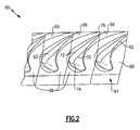
- the turbine section 28, the compressor section 24, or a fan exit guide vane 25 may include at least one airfoil array 60 as shown in Figure 2 .
- the airfoil array 60 is comprised of a plurality of airfoils 62 projecting radially from an endwall 64.
- the airfoils 62 may be provided as a stage of rotor blades or stator vanes in the compressor section 24 or the turbine section 28.
- the endwall 64 may be either an inner diameter endwall or an outer diameter endwall or both.
- the airfoils 62 are circumferentially spaced apart from each other about the engine center axis A to define a plurality of flow passages 66 between adjacent airfoils 62.
- Each airfoil 62 is supported by a platform 68 that forms part of the endwall 64.
- Each airfoil 62 has a first side 70 and a second side 72 that extend from a leading edge 74 to a trailing edge 76. Fluid flow moves toward the flow passages 66 from a position forward of the leading edge 74 as indicated by the arrow 78 in Figure 3 .
- the endwall 64 extends circumferentially about the engine center axis A and is defined by the adjacent platforms 68. Each pair of adjacent platforms 68 are separated from each other by a gap 80 as shown in Figure 3 .
- the endwall 64 is configured to have an endwall contour shape defined to extend from a first location on one side of the gap 80 to a second location on an opposite of the gap 80. This endwall contour shape is a common shape for all adjacent platforms 68 regardless of the type of airfoil 62. This will be discussed in greater detail below.
- Figure 3 shows an example where two different types of airfoils 62 are located adjacent to each other.
- a first type of airfoil 62a is supported on a first platform 68a and a second type of airfoil 62b is supported on a second platform 68b.
- the types of airfoils differ from each other, for example, in curvature as the airfoils 62a, 62b extend from the leading edge 74 to the trailing edge 76, and/or in location on the respective platform 68a, 68b.
- a trailing edge area 82 which corresponds to an exit area for the flow passages 66, varies between the adjacent trailing edges 76 of the airfoils 62, 62a, 62b. It should be noted that while two different types of airfoils 62a, 62b are schematically shown in the examples, additional types of airfoils having other shapes and geometries could also be utilized in the array 60.
- the different platforms 68a, 68b present varying platform geometries from passage 66 to passage 66. These variations create a mismatch at the platform gap. This mismatch is aerodynamically undesirable as it increases losses. Additionally, different seals (not shown) will be required to seal the gaps 80 for each different combination of adjacent platforms 68.
- Figure 4 is a front view of two adjacent platforms 68a for the first type of airfoil 62a.
- a first endwall contour shape 84 is positioned on one side of the gap 80 and a second endwall contour shape 86 is positioned on an opposite side of the gap 80.
- the first 84 and second 86 endwall contour shapes terminate at locations 84a, 86a that directly face each other across the gap 80.
- Figure 5 is a front view of two adjacent platforms 68b for the second type of airfoil 62b.
- a first endwall contour shape 88 is positioned on one side of the gap 80 and a second endwall contour shape 90 is positioned on an opposite side of the gap 80.
- the first 88 and second 90 endwall contour shapes terminate at locations 88a, 90a that are not directly across from each other at the gap 80.
- the first location 88a is above the second location 90a, i.e. the locations 88a, 90a are offset from each other.
- a continuously smooth surface made up of the seal and endwall contour shapes 88 and 90 will be created.
- Figure 6 is a front view of showing a first type of platform 68a adjacent to a second type of platform 68b.
- the first type of platform 68a has the second endwall contour shape 86 (as shown in Figure 4 ) on the right side of the gap 80 when viewing Figure 6 .
- the second type of platform 68b has the first endwall contour shape 88 (as shown in Figure 5 ) on the left side of the gap 80.
- the first endwall contour shape 88 and second endwall contour shape 86 terminate at locations 88a, 86b that are not directly across from each other at the gap 80.
- the first location 88a is below the second location 86b, i.e. the locations are offset from each other.
- the offset shown in Figure 6 is different than the offset shown in Figure 5 .
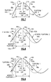
- the subject invention provides a common endwall shape in a region 100 near the platform gap 80 as shown in Figures 7-9 .
- the endwall shape is identical regardless of the overall platform geometry.
- the endwall contouring would vary to smoothly blend back into the optimal design shape for the respective airfoil.
- the edges 104, 106 are located at predetermined locations on either side of the gap 80.
- An endwall segment that includes the areas 102a, 102b and the region 100 extends between facing sides of adjacent airfoils.
- Figure 7 shows a front view of two adjacent platforms 68a for the first type of airfoil 62a.
- the first endwall contour shape 84 and second endwall contour shape 86 are the same as those shown in Figure 4 .
- the first 84 and second 86 endwall contour shapes terminate at edge locations 110, 112 that respectively correspond to the edges 104, 106 of the common endwall contour region 100.
- Within the common region 100 there is a first endwall region shape 114 on one side of the gap 80 and a second endwall region shape 116 on the opposite side of the gap 80.
- Figure 8 shows a front view of two adjacent platforms 68b for the second type of airfoils 62b.
- the first endwall contour shape 88 and the second endwall contour shape 90 are shown in dotted lines.
- the first endwall contour shape 88 and second endwall contour shape 90 are the same as those shown in Figure 5 . Portions of these contour shapes 88, 90 are modified within the common region 100 to match the shapes shown in Figure 7 .
- the first endwall contour shape 88 is shaped to be identical to the first endwall region shape 114 and the second endwall contour shape 90 is shaped to be identical to the second endwall region shape 116.
- the endwall shape for the remaining area 102a is blended back into the first endwall contour shape 88 as indicated at 120.
- the second endwall contour shape 116 reaches the edge location 112
- the endwall shape for the remaining area 102b is blended back into the second endwall contour shape 90 as indicated at 122.
- the endwall contour shapes for the two adjacent second platform types 68b terminate at the same locations 84a, 86a across the gap 80 as with two adjacent first platform types 68a.
- Figure 9 shows a front view of a first type of platform 68a adjacent to a second type of platform 68b.
- the first type of platform 68a has the second endwall contour shape 86 (identical to that of Figure 7 ) on the right side of the gap 80 when viewing Figure 9 .
- the second type of platform 68b has the first endwall contour shape 88 (as shown in dashed lines) on the left side of the gap 80.
- the second endwall contour shape 86 is identical to the shape shown in Figure 7 , there is no need to modify the first type of platform 68a within the common region 100.
- a portion the first contour shape 88 is modified within the common region 100 to match the shape shown in Figure 7 .
- the first endwall contour shape 88 is shaped to be identical to the first endwall region shape 114 and the second endwall contour shape 86 is already shaped to be identical to the second endwall region shape 116.
- the endwall shape for the remaining area 102a is blended back into the first endwall contour shape 88 as indicated at 130.
- the second endwall contour shape 86 reaches the edge location 112, it remains the identical shape to that shown in Figure 7 .
- the endwall contour shapes for a first type of platform 68a adjacent to a second type of platform 68b terminate at the same locations 84a, 86a across the gap 80 as with two adjacent first platform types 68a and as with two adjacent second platform types 68b.
- the subject invention allows for common platform to platform interface regardless of which combination of adjacent platforms is used. By eliminating the mismatch at the platform gap, the aerodynamic impact of using endwall contouring for arrays with rows having varying platform geometry is improved. Further, only one type of platform gap seal is required, which reduces the number of parts and cost associated with the endwall contouring design.
Landscapes
- Engineering & Computer Science (AREA)
- Mechanical Engineering (AREA)
- General Engineering & Computer Science (AREA)
- Physics & Mathematics (AREA)
- Fluid Mechanics (AREA)
- Geometry (AREA)
- Architecture (AREA)
- Structures Of Non-Positive Displacement Pumps (AREA)
- Turbine Rotor Nozzle Sealing (AREA)
Abstract
Description
- In rotating turbomachinery, such as compressor and turbine stages of gas turbine engines, flow passages are defined by airfoil surfaces and an endwall. The airfoils are supported on platform structures that are circumferentially spaced about an engine center axis. The platform structures together form the endwall. Each platform structure is separated from an adjacent platform structure by a gap. Seals are provided at these gaps to seal the flow passages.
- When defining the endwall contour shape for compressor or turbine rows that have varying platform geometries from passage to passage, typically due to strut machining, the contoured endwall shape has to vary to fit within the passage shape. Whether the endwall shape is scaled to fit the passage, or is specifically designed for each passage, a mismatch might be created at the platform gap. This mismatch is aerodynamically undesirable as it will result in an increase in loss. Also, different seals will be required to seal the gap between each combination of adjacent platforms, which increases cost.
- In a featured embodiment, an airfoil array for a gas turbine engine comprises a plurality of airfoils spaced circumferentially apart from each other about an engine center axis. Each airfoil is associated with a platform. An endwall extends circumferentially about the engine center axis, and is defined by adjacent platforms. Each pair of adjacent platforms are separated from each other by a gap. An endwall contour shape extends from a first location on one side of the gap to a second location on an opposite of the gap. The endwall contour shape is the same for all adjacent platforms.
- In another embodiment according to the previous embodiment, the plurality of airfoils includes at least a first airfoil type and a second airfoil type that is different than the first airfoil type.
- In another embodiment according to any of the previous embodiments, the plurality of airfoils includes a pair of first airfoil types that are adjacent to each other with each first airfoil type having a first platform type. The endwall contour shape comprises a first endwall contour shape that is defined by a first portion extending from the first location on one of the first platform types to the gap and a second portion extending from the opposite side of the gap to the second location on the other of the first platform types. The shape includes a first additional endwall contour extending from the first location to a first area adjacent to the airfoil associated with the one of the first platform types, and a second additional endwall contour extending from the second location to a second area adjacent to the airfoil associated with the other of the first platform types.
- In another embodiment according to any of the previous embodiments, the plurality of airfoils includes a pair of second airfoil types that are adjacent to each other with each second airfoil type having a second platform type. The endwall contour shape further comprises a second endwall contour shape that is defined by a first portion extending from the first location on one of the second platform types to the gap and a second portion extending from the opposite side of the gap to the second location on the other of the second platform types. The shape includes a third additional endwall contour extending from the first location to a third area adjacent to the airfoil associated with the one of the second platform types and a fourth additional endwall contour extending from the second location to a fourth area adjacent to the airfoil associated with the other of the second platform types. The second endwall contour shape is identical to the first endwall contour shape.
- In another embodiment according to any of the previous embodiments, the first additional endwall contour is different than the second additional endwall contour.
- In another embodiment according to any of the previous embodiments, the third additional endwall contour is different than the fourth additional endwall contour.
- In another embodiment according to any of the previous embodiments, the first and second additional endwall contours are different than the third and fourth additional endwall contours.
- In another embodiment according to any of the previous embodiments, the plurality of airfoils includes a first airfoil type adjacent to a second airfoil type. The endwall contour shape further comprises a third endwall contour shape that is defined by a first portion extending from the first location on the first platform type to the gap and a second portion extending from the opposite side of the gap to the second location on the second platform type. A fifth additional endwall contour is included extending from the first location to a fifth area adjacent to the airfoil associated with the first platform type and a sixth additional endwall contour extending from the second location to a sixth area adjacent to the airfoil associated with the second platform type. The third endwall contour shape is identical to the first and second endwall contour shapes.
- In another embodiment according to any of the previous embodiments, the endwall contour shape defines a first endwall portion. The first location is on a first platform with a first airfoil and the second location is on a second platform with a second airfoil. The first location is circumferentially spaced apart from a side of the first airfoil by a first distance that defines a second endwall portion. The second location is circumferentially spaced apart from a side of the second airfoil by a second distance to form a third end wall portion such that an endwall segment extends from the first airfoil to the second endwall and is entirely defined by the first, second, and third endwall portions.
- In another embodiment according to any of the previous embodiments, the first and second airfoils are different types from each other or are the same type as each other. The first end wall portion is the same when the first and second airfoils are different from, or the same as, each other.
- In another featured embodiment, a gas turbine engine comprises a compressor section, a combustor section downstream of the compressor section, and a turbine section downstream of the combustor section. At least one of the combustor section, the turbine section, or a fan exit guide vane section, include an airfoil array that is comprised of a plurality of airfoils spaced circumferentially apart from each other about an engine center axis. Each airfoil is associated with a platform. An endwall extends circumferentially about the engine center axis. The endwall is defined by adjacent platforms. Each pair of adjacent platforms are separated from each other by a gap. The plurality of airfoils includes at least a first airfoil on a first platform and a second airfoil on a second platform. The first and second platforms are separated from each other by the gap. An endwall contour shape is defined to extend from a first location on the first platform to a second location on the second platform. The endwall contour shape is the same for all adjacent platforms.
- In another embodiment according to the previous embodiment, an endwall segment extends from one side of the first airfoil and across the gap to a side of the second airfoil that faces the first airfoil. The endwall contour shape defines a first endwall portion of the endwall segment. The first location is circumferentially spaced apart from the side of the first airfoil by a first distance that defines a second endwall portion. The second location is circumferentially spaced apart from the side of the second airfoil by a second distance to form a third end wall portion such that the endwall segment is entirely defined by the first, second, and third endwall portions.
- In another embodiment according to any of the previous embodiments, the first and second airfoils are different types from each other or are the same type as each other. The first end wall portion is the same if the first and second airfoils are different from each other or if the first and second airfoils are the same as each other.
- In another embodiment according to any of the previous embodiments, the second and third endwall portions are different from the first end wall portion.
- In another embodiment according to any of the previous embodiments, the second and third endwall portions are different from each other.
- In another featured embodiment, a method of forming an airfoil array for a gas turbine engine comprises the steps of spacing a plurality of airfoils circumferentially apart from each other about an engine center axis. Each airfoil is associated with a platform. An endwall is formed that extends circumferentially about the engine center axis. The endwall is defined by adjacent platforms. Each pair of adjacent platforms are separated from each other by a gap. The plurality of airfoils includes at least a first airfoil on a first platform and a second airfoil on a second platform with the first and second platforms being separated from each other by the gap. An endwall contour is shaped to extend from a first location on the first platform to a second location on the second platform. The endwall contour is shaped to be the same for all adjacent platforms regardless of airfoil type.
- In another embodiment according to the previous embodiment, an endwall segment is defined as extending from one side of the first airfoil, across the gap, and to a side of the second airfoil that faces the first airfoil. The endwall contour is defined to comprise a first endwall portion of the endwall segment. The first location is spaced circumferentially apart from the side of the first airfoil by a first distance that defines a second endwall portion. The second location is spaced circumferentially apart from the side of the second airfoil by a second distance to form a third end wall portion such that the endwall segment is entirely defined by the first, second, and third endwall portions.
- In another embodiment according to any of the previous embodiments, the first and second airfoils are different types from each other or are the same type as each other. The first end wall portion is the same if the first and second airfoils are different from each other or if the first and second airfoils are the same as each other.
- In another embodiment according to any of the previous embodiments, the first and second airfoils are different types from each other, and include blending a first transition from the first location to match a platform profile for the first airfoil type to form the second endwall portion, and blending a second transition from the second location to match a platform profile for the second airfoil type to form the third endwall portion.
- In another embodiment according to any of the previous embodiments, the second and third endwall portions are different from the first end wall portion, and are different from each other.
- These and other features may be best understood from the following drawings and specification.
-
-
Figure 1 is a schematic representation of one example of a gas turbine engine. -
Figure 2 is a top view of an array of airfoils on an endwall. -
Figure 3 is a schematic top view of an array showing at least two different types of airfoils. -
Figure 4 is a schematic front view of two adjacent airfoils of the first type. -
Figure 5 is a schematic front view of two adjacent airfoils of the second type. -
Figure 6 is a schematic front view of a first type of airfoil adjacent to a second type of airfoil. -
Figure 7 is a schematic front view of a common endwall contour region for two adjacent airfoils of the first type. -
Figure 8 is a schematic front view of a common endwall contour region for two adjacent airfoils of the second type. -
Figure 9 is a schematic front view of a common endwall contour region for a first type of airfoil adjacent to a second type of airfoil. -
Figure 1 schematically illustrates agas turbine engine 20. Thegas turbine engine 20 is disclosed herein as a two-spool turbofan that generally incorporates afan section 22, acompressor section 24, acombustor section 26 and aturbine section 28. Alternative engines might include an augmentor section (not shown) among other systems or features. Thefan section 22 drives air along a bypass flow path B in a bypass duct defined within anacelle 15, while thecompressor section 24 drives air along a core flow path C for compression and communication into thecombustor section 26 then expansion through theturbine section 28. Although depicted as a two-spool turbofan gas turbine engine in the disclosed non-limiting embodiment, it should be understood that the concepts described herein are not limited to use with two-spool turbofans as the teachings may be applied to other types of turbine engines including three-spool architectures. - The
exemplary engine 20 generally includes alow speed spool 30 and ahigh speed spool 32 mounted for rotation about an engine central longitudinal axis A relative to an enginestatic structure 36 viaseveral bearing systems 38. It should be understood that various bearingsystems 38 at various locations may alternatively or additionally be provided, and the location of bearingsystems 38 may be varied as appropriate to the application. - The
low speed spool 30 generally includes aninner shaft 40 that interconnects afan 42, a first (or low) pressure compressor 44 and a first (or low)pressure turbine 46. Theinner shaft 40 is connected to thefan 42 through a speed change mechanism, which in exemplarygas turbine engine 20 is illustrated as a gearedarchitecture 48 to drive thefan 42 at a lower speed than thelow speed spool 30. Thehigh speed spool 32 includes anouter shaft 50 that interconnects a second (or high)pressure compressor 52 and a second (or high)pressure turbine 54. Acombustor 56 is arranged inexemplary gas turbine 20 between thehigh pressure compressor 52 and thehigh pressure turbine 54. Amid-turbine frame 57 of the enginestatic structure 36 is arranged generally between thehigh pressure turbine 54 and thelow pressure turbine 46. Themid-turbine frame 57 furthersupports bearing systems 38 in theturbine section 28. Theinner shaft 40 and theouter shaft 50 are concentric and rotate via bearingsystems 38 about the engine central longitudinal axis A which is collinear with their longitudinal axes. - The core airflow is compressed by the low pressure compressor 44 then the
high pressure compressor 52, mixed and burned with fuel in thecombustor 56, then expanded over thehigh pressure turbine 54 andlow pressure turbine 46. Themid-turbine frame 57 includesairfoils 59 which are in the core airflow path C. Theturbines low speed spool 30 andhigh speed spool 32 in response to the expansion. It will be appreciated that each of the positions of thefan section 22,compressor section 24,combustor section 26,turbine section 28, and fandrive gear system 48 may be varied. For example,gear system 48 may be located aft ofcombustor section 26 or even aft ofturbine section 28, andfan section 22 may be positioned forward or aft of the location ofgear system 48. - The
engine 20 in one example is a high-bypass geared aircraft engine. In a further example, theengine 20 bypass ratio is greater than about six (6), with an example embodiment being greater than about ten (10), the gearedarchitecture 48 is an epicyclic gear train, such as a planetary gear system or other gear system, with a gear reduction ratio of greater than about 2.3 and thelow pressure turbine 46 has a pressure ratio that is greater than about five. In one disclosed embodiment, theengine 20 bypass ratio is greater than about ten (10:1), the fan diameter is significantly larger than that of the low pressure compressor 44, and thelow pressure turbine 46 has a pressure ratio that is greater than about five 5:1.Low pressure turbine 46 pressure ratio is pressure measured prior to inlet oflow pressure turbine 46 as related to the pressure at the outlet of thelow pressure turbine 46 prior to an exhaust nozzle. The gearedarchitecture 48 may be an epicycle gear train, such as a planetary gear system or other gear system, with a gear reduction ratio of greater than about 2.3:1. It should be understood, however, that the above parameters are only exemplary of one embodiment of a geared architecture engine and that the present invention is applicable to other gas turbine engines including direct drive turbofans. - A significant amount of thrust is provided by the bypass flow B due to the high bypass ratio. The
fan section 22 of theengine 20 is designed for a particular flight condition -- typically cruise at about 0.8 Mach and about 35,000 feet (10668 m). The flight condition of 0.8 Mach and 35,000 ft (10668 m), with the engine at its best fuel consumption - also known as "bucket cruise Thrust Specific Fuel Consumption ('TSFC')" - is the industry standard parameter of lbm of fuel being burned divided by lbf of thrust the engine produces at that minimum point. "Low fan pressure ratio" is the pressure ratio across the fan blade alone, without a Fan Exit Guide Vane ("FEGV") system. The low fan pressure ratio as disclosed herein according to one non-limiting embodiment is less than about 1.45. "Low corrected fan tip speed" is the actual fan tip speed in ft/sec divided by an industry standard temperature correction of [(Tram °R) / (518.7 °R)]0.5. The "Low corrected fan tip speed" as disclosed herein according to one non-limiting embodiment is less than about 1150 ft / second (350.5 m/s). - The
turbine section 28, thecompressor section 24, or a fanexit guide vane 25 may include at least oneairfoil array 60 as shown inFigure 2 . Theairfoil array 60 is comprised of a plurality ofairfoils 62 projecting radially from anendwall 64. For example, theairfoils 62 may be provided as a stage of rotor blades or stator vanes in thecompressor section 24 or theturbine section 28. Theendwall 64 may be either an inner diameter endwall or an outer diameter endwall or both. Theairfoils 62 are circumferentially spaced apart from each other about the engine center axis A to define a plurality offlow passages 66 betweenadjacent airfoils 62. - Each
airfoil 62 is supported by aplatform 68 that forms part of theendwall 64. Eachairfoil 62 has afirst side 70 and asecond side 72 that extend from a leadingedge 74 to a trailingedge 76. Fluid flow moves toward theflow passages 66 from a position forward of the leadingedge 74 as indicated by thearrow 78 inFigure 3 . - The
endwall 64 extends circumferentially about the engine center axis A and is defined by theadjacent platforms 68. Each pair ofadjacent platforms 68 are separated from each other by agap 80 as shown inFigure 3 . Theendwall 64 is configured to have an endwall contour shape defined to extend from a first location on one side of thegap 80 to a second location on an opposite of thegap 80. This endwall contour shape is a common shape for alladjacent platforms 68 regardless of the type ofairfoil 62. This will be discussed in greater detail below. -
Figure 3 shows an example where two different types ofairfoils 62 are located adjacent to each other. A first type ofairfoil 62a is supported on afirst platform 68a and a second type ofairfoil 62b is supported on asecond platform 68b. The types of airfoils differ from each other, for example, in curvature as theairfoils edge 74 to the trailingedge 76, and/or in location on therespective platform airfoils edge area 82, which corresponds to an exit area for theflow passages 66, varies between theadjacent trailing edges 76 of theairfoils airfoils array 60. - The
different platforms passage 66 topassage 66. These variations create a mismatch at the platform gap. This mismatch is aerodynamically undesirable as it increases losses. Additionally, different seals (not shown) will be required to seal thegaps 80 for each different combination ofadjacent platforms 68. -
Figure 4 is a front view of twoadjacent platforms 68a for the first type ofairfoil 62a. A firstendwall contour shape 84 is positioned on one side of thegap 80 and a secondendwall contour shape 86 is positioned on an opposite side of thegap 80. In this example, the first 84 and second 86 endwall contour shapes terminate atlocations gap 80. -
Figure 5 is a front view of twoadjacent platforms 68b for the second type ofairfoil 62b. A firstendwall contour shape 88 is positioned on one side of thegap 80 and a secondendwall contour shape 90 is positioned on an opposite side of thegap 80. In this example, the first 88 and second 90 endwall contour shapes terminate atlocations gap 80. Thefirst location 88a is above thesecond location 90a, i.e. thelocations gap 80 is sealed, a continuously smooth surface made up of the seal and endwall contour shapes 88 and 90 will be created. -
Figure 6 is a front view of showing a first type ofplatform 68a adjacent to a second type ofplatform 68b. The first type ofplatform 68a has the second endwall contour shape 86 (as shown inFigure 4 ) on the right side of thegap 80 when viewingFigure 6 . The second type ofplatform 68b has the first endwall contour shape 88 (as shown inFigure 5 ) on the left side of thegap 80. In this example, the firstendwall contour shape 88 and secondendwall contour shape 86 terminate atlocations 88a, 86b that are not directly across from each other at thegap 80. Thefirst location 88a is below the second location 86b, i.e. the locations are offset from each other. The offset shown inFigure 6 is different than the offset shown inFigure 5 . Once the gap is sealed, the surface created by the seal and endwall contour shapes 86 and 88 will not be smooth and continuous. - The subject invention provides a common endwall shape in a
region 100 near theplatform gap 80 as shown inFigures 7-9 . Within thisregion 100, the endwall shape is identical regardless of the overall platform geometry. Outside of theregion 100 in the remainingareas respective airfoils edges common region 100, the endwall contouring would vary to smoothly blend back into the optimal design shape for the respective airfoil. Theedges gap 80. An endwall segment that includes theareas region 100 extends between facing sides of adjacent airfoils. -
Figure 7 shows a front view of twoadjacent platforms 68a for the first type ofairfoil 62a. The firstendwall contour shape 84 and secondendwall contour shape 86 are the same as those shown inFigure 4 . In this example, the first 84 and second 86 endwall contour shapes terminate atedge locations edges endwall contour region 100. Within thecommon region 100 there is a first endwall region shape 114 on one side of thegap 80 and a second endwall region shape 116 on the opposite side of thegap 80. -
Figure 8 shows a front view of twoadjacent platforms 68b for the second type ofairfoils 62b. The firstendwall contour shape 88 and the secondendwall contour shape 90 are shown in dotted lines. The firstendwall contour shape 88 and secondendwall contour shape 90 are the same as those shown inFigure 5 . Portions of these contour shapes 88, 90 are modified within thecommon region 100 to match the shapes shown inFigure 7 . Thus, within thecommon region 100, the firstendwall contour shape 88 is shaped to be identical to the firstendwall region shape 114 and the secondendwall contour shape 90 is shaped to be identical to the secondendwall region shape 116. Once the firstendwall region shape 114 reaches theedge location 110, the endwall shape for the remainingarea 102a is blended back into the firstendwall contour shape 88 as indicated at 120. Once the secondendwall contour shape 116 reaches theedge location 112, the endwall shape for the remainingarea 102b is blended back into the secondendwall contour shape 90 as indicated at 122. Thus, the endwall contour shapes for the two adjacent second platform types 68b terminate at thesame locations gap 80 as with two adjacentfirst platform types 68a. -
Figure 9 shows a front view of a first type ofplatform 68a adjacent to a second type ofplatform 68b. The first type ofplatform 68a has the second endwall contour shape 86 (identical to that ofFigure 7 ) on the right side of thegap 80 when viewingFigure 9 . The second type ofplatform 68b has the first endwall contour shape 88 (as shown in dashed lines) on the left side of thegap 80. As the secondendwall contour shape 86 is identical to the shape shown inFigure 7 , there is no need to modify the first type ofplatform 68a within thecommon region 100. A portion thefirst contour shape 88 is modified within thecommon region 100 to match the shape shown inFigure 7 . Thus, within thecommon region 100, the firstendwall contour shape 88 is shaped to be identical to the firstendwall region shape 114 and the secondendwall contour shape 86 is already shaped to be identical to the secondendwall region shape 116. - Once the first
endwall region shape 114 reaches theedge location 110, the endwall shape for the remainingarea 102a is blended back into the firstendwall contour shape 88 as indicated at 130. Once the secondendwall contour shape 86 reaches theedge location 112, it remains the identical shape to that shown inFigure 7 . Thus, the endwall contour shapes for a first type ofplatform 68a adjacent to a second type ofplatform 68b terminate at thesame locations gap 80 as with two adjacentfirst platform types 68a and as with two adjacentsecond platform types 68b. - The subject invention allows for common platform to platform interface regardless of which combination of adjacent platforms is used. By eliminating the mismatch at the platform gap, the aerodynamic impact of using endwall contouring for arrays with rows having varying platform geometry is improved. Further, only one type of platform gap seal is required, which reduces the number of parts and cost associated with the endwall contouring design.
- Although an embodiment of this invention has been disclosed, a worker of ordinary skill in this art would recognize that certain modifications would come within the scope of this invention. For that reason, the following claims should be studied to determine the true scope and content of this invention.
Claims (15)
- An airfoil array (60) for a gas turbine engine comprising:a plurality of airfoils (62) spaced circumferentially apart from each other about an engine center axis, each airfoil (62) being associated with a platform (68);an endwall (64) extending circumferentially about the engine center axis, the endwall (64) being defined by adjacent platforms (68), and wherein each pair of adjacent platforms (68) are separated from each other by a gap (80); andan endwall contour shape defined to extend from a first location on one side of the gap (80) to a second location on an opposite of the gap (80), and wherein the endwall contour shape is the same for all adjacent platforms (68).
- The airfoil array according to claim 1, wherein the plurality of airfoils includes at least a first airfoil type (62a) and a second airfoil type (62b) that is different than the first airfoil type (62a).
- The airfoil array according to claim 2, wherein the plurality of airfoils includes a pair of first airfoil types (62a) that are adjacent to each other with each first airfoil type (62a) having a first platform type, and wherein the endwall contour shape comprises a first endwall contour shape that is defined by a first portion extending from the first location on one of the first platform types to the gap (80) and a second portion extending from the opposite side of the gap (80) to the second location on the other of the first platform types, and including a first additional endwall contour extending from the first location to a first area adjacent to the airfoil associated with the one of the first platform types and a second additional endwall contour extending from the second location to a second area adjacent to the airfoil associated with the other of the first platform types.
- The airfoil array according to claim 3, wherein the plurality of airfoils includes a pair of second airfoil types (62b) that are adjacent to each other with each second airfoil type (62b) having a second platform type, and wherein the endwall contour shape further comprises a second endwall contour shape that is defined by a first portion extending from the first location on one of the second platform types to the gap (80) and a second portion extending from the opposite side of the gap (80) to the second location on the other of the second platform types, and including a third additional endwall contour extending from the first location to a third area adjacent to the airfoil associated with the one of the second platform types and a fourth additional endwall contour extending from the second location to a fourth area adjacent to the airfoil associated with the other of the second platform types, and wherein the second endwall contour shape is identical to the first endwall contour shape.
- The airfoil array according to claim 4, wherein the plurality of airfoils includes a first airfoil type (62a) adjacent to a second airfoil type (62b), and wherein the endwall contour shape further comprises a third endwall contour shape that is defined by a first portion extending from the first location on the first platform type to the gap (80) and a second portion extending from the opposite side of the gap (80) to the second location on the second platform type, and including a fifth additional endwall contour extending from the first location to a fifth area adjacent to the airfoil associated with the first platform type and a sixth additional endwall contour extending from the second location to a sixth area adjacent to the airfoil associated with the second platform type, and wherein the third endwall contour shape is identical to the first and second endwall contour shapes.
- The airfoil array according to any preceding claim, wherein the endwall contour shape defines a first endwall portion, and wherein the first location is on a first platform with a first airfoil and the second location is on a second platform with a second airfoil, and wherein the first location is circumferentially spaced apart from a side of the first airfoil by a first distance that defines a second endwall portion, and wherein the second location is circumferentially spaced apart from a side of the second airfoil by a second distance to form a third end wall portion such that an endwall segment extending from the first airfoil to the second endwall is entirely defined by the first, second, and third endwall portions.
- A gas turbine engine (20) comprising:a compressor section (24);a combustor section (26) downstream of the compressor section (24); anda turbine section (28) downstream of the combustor section (26), and wherein at least one of the combustor section (24), the turbine section (28), or a fan exit guide vane section, include an airfoil array (60) that is comprised of
a plurality of airfoils (62) spaced circumferentially apart from each other about an engine center axis, each airfoil (62) being associated with a platform (68),
an endwall (64) extending circumferentially about the engine center axis, the endwall (64) being defined by adjacent platforms (68), and wherein each pair of adjacent platforms (68) are separated from each other by a gap (80), and
wherein the plurality of airfoils includes at least a first airfoil (62) on a first platform (68) and a second airfoil (62) on a second platform (68) with the first and second platforms (68) being separated from each other by the gap (80); and
an endwall contour shape defined to extend from a first location on the first platform (68) to a second location on the second platform (68), and wherein the endwall contour shape is the same for all adjacent platforms (68). - The gas turbine engine according to claim 7, wherein an endwall segment is defined as extending from one side of the first airfoil (68) and across the gap (80) to a side of the second airfoil (62) that faces the first airfoil (62), and wherein the endwall contour shape defines a first endwall portion of the endwall segment, and wherein the first location is circumferentially spaced apart from the side of the first airfoil (62) by a first distance that defines a second endwall portion, and wherein the second location is circumferentially spaced apart from the side of the second airfoil (62) by a second distance to form a third end wall portion such that the endwall segment is entirely defined by the first, second, and third endwall portions.
- The gas turbine engine according to claim 8, wherein the first and second airfoils (62a, 62b) are different types from each other or are the same type as each other, and wherein the first end wall portion is the same if the first and second airfoils are different from each other or if the first and second airfoils are the same as each other.
- The gas turbine engine according to claim 9, wherein the second and third endwall portions are different from the first end wall portion.
- The gas turbine engine according to claim 10, wherein the second and third endwall portions are different from each other.
- A method of forming an airfoil array (60) for a gas turbine engine comprising the steps of:spacing a plurality of airfoils (62) circumferentially apart from each other about an engine center axis, each airfoil (62) being associated with a platform (68);forming an endwall (64) that extends circumferentially about the engine center axis, the endwall (64) being defined by adjacent platforms (68), and wherein each pair of adjacent platforms (68) are separated from each other by a gap (80);wherein the plurality of airfoils includes at least a first airfoil (62) on a first platform (68) and a second airfoil (62) on a second platform (68) with the first and second platforms (68) being separated from each other by the gap (80); andshaping an endwall contour to extend from a first location on the first platform (68) to a second location on the second platform (68), wherein the endwall contour is shaped to be the same for all adjacent platforms (68) regardless of airfoil type.
- The method according to claim 12 including
defining an endwall segment as extending from one side of the first airfoil (62), across the gap (80), and to a side of the second airfoil (62) that faces the first airfoil (62),
defining the endwall contour to comprise a first endwall portion of the endwall segment,
spacing the first location circumferentially apart from the side of the first airfoil by a first distance that defines a second endwall portion, and
spacing the second location circumferentially apart from the side of the second airfoil by a second distance to form a third end wall portion such that the endwall segment is entirely defined by the first, second, and third endwall portions. - The method according to claim 13, wherein the first and second airfoils (62a, 62b) are different types from each other or are the same type as each other, and wherein the first end wall portion is the same if the first and second airfoils (62a, 62b) are different from each other or if the first and second airfoils (62a, 62b) are the same as each other.
- The method according to claim 14, wherein the first and second airfoils (62a, 62b) are different types from each other, and including blending a first transition from the first location to match a platform profile for the first airfoil type to form the second endwall portion, and blending a second transition from the second location to match a platform profile for the second airfoil type to form the third endwall portion.
Priority Applications (1)
| Application Number | Priority Date | Filing Date | Title |
|---|---|---|---|
| EP22192486.3A EP4116543A1 (en) | 2014-09-12 | 2015-09-09 | Endwall contouring for airfoil rows with varying airfoil geometries |
Applications Claiming Priority (1)
| Application Number | Priority Date | Filing Date | Title |
|---|---|---|---|
| US201462049391P | 2014-09-12 | 2014-09-12 |
Related Child Applications (1)
| Application Number | Title | Priority Date | Filing Date |
|---|---|---|---|
| EP22192486.3A Division EP4116543A1 (en) | 2014-09-12 | 2015-09-09 | Endwall contouring for airfoil rows with varying airfoil geometries |
Publications (2)
| Publication Number | Publication Date |
|---|---|
| EP2998509A1 true EP2998509A1 (en) | 2016-03-23 |
| EP2998509B1 EP2998509B1 (en) | 2022-08-31 |
Family
ID=54072764
Family Applications (2)
| Application Number | Title | Priority Date | Filing Date |
|---|---|---|---|
| EP22192486.3A Withdrawn EP4116543A1 (en) | 2014-09-12 | 2015-09-09 | Endwall contouring for airfoil rows with varying airfoil geometries |
| EP15184513.8A Active EP2998509B1 (en) | 2014-09-12 | 2015-09-09 | Endwall contouring for airfoil rows with varying airfoil geometries |
Family Applications Before (1)
| Application Number | Title | Priority Date | Filing Date |
|---|---|---|---|
| EP22192486.3A Withdrawn EP4116543A1 (en) | 2014-09-12 | 2015-09-09 | Endwall contouring for airfoil rows with varying airfoil geometries |
Country Status (2)
| Country | Link |
|---|---|
| US (1) | US10151210B2 (en) |
| EP (2) | EP4116543A1 (en) |
Cited By (1)
| Publication number | Priority date | Publication date | Assignee | Title |
|---|---|---|---|---|
| EP3219914A1 (en) * | 2016-03-17 | 2017-09-20 | MTU Aero Engines GmbH | Flow channel, corresponding blade row and turbomachine |
Families Citing this family (5)
| Publication number | Priority date | Publication date | Assignee | Title |
|---|---|---|---|---|
| US20180179952A1 (en) * | 2016-12-23 | 2018-06-28 | General Electric Company | Rotating detonation engine and method of operating same |
| US11002293B2 (en) | 2017-09-15 | 2021-05-11 | Pratt & Whitney Canada Corp. | Mistuned compressor rotor with hub scoops |
| US10443411B2 (en) | 2017-09-18 | 2019-10-15 | Pratt & Whitney Canada Corp. | Compressor rotor with coated blades |
| US10837459B2 (en) | 2017-10-06 | 2020-11-17 | Pratt & Whitney Canada Corp. | Mistuned fan for gas turbine engine |
| US11359506B2 (en) * | 2020-01-13 | 2022-06-14 | Raytheon Technologies Corporation | Contoured stop for variable area turbine |
Citations (4)
| Publication number | Priority date | Publication date | Assignee | Title |
|---|---|---|---|---|
| US20120099995A1 (en) * | 2010-10-20 | 2012-04-26 | General Electric Company | Rotary machine having spacers for control of fluid dynamics |
| WO2013186756A1 (en) * | 2012-06-14 | 2013-12-19 | Avio S.P.A. | Aerofoil array for a gas turbine with anti fluttering means |
| US20140072432A1 (en) * | 2011-04-01 | 2014-03-13 | Mtu Aero Engines Gmbh | Blade arrangement for a turbo engine |
| WO2014130332A1 (en) * | 2013-02-21 | 2014-08-28 | United Technologies Corporation | Gas turbine engine having a mistuned stage |
Family Cites Families (12)
| Publication number | Priority date | Publication date | Assignee | Title |
|---|---|---|---|---|
| US6663346B2 (en) | 2002-01-17 | 2003-12-16 | United Technologies Corporation | Compressor stator inner diameter platform bleed system |
| US6669445B2 (en) | 2002-03-07 | 2003-12-30 | United Technologies Corporation | Endwall shape for use in turbomachinery |
| US7600972B2 (en) | 2003-10-31 | 2009-10-13 | General Electric Company | Methods and apparatus for cooling gas turbine engine rotor assemblies |
| US7090466B2 (en) | 2004-09-14 | 2006-08-15 | General Electric Company | Methods and apparatus for assembling gas turbine engine rotor assemblies |
| US7708528B2 (en) | 2005-09-06 | 2010-05-04 | United Technologies Corporation | Platform mate face contours for turbine airfoils |
| US7874794B2 (en) | 2006-03-21 | 2011-01-25 | General Electric Company | Blade row for a rotary machine and method of fabricating same |
| US8105019B2 (en) | 2007-12-10 | 2012-01-31 | United Technologies Corporation | 3D contoured vane endwall for variable area turbine vane arrangement |
| US8459956B2 (en) * | 2008-12-24 | 2013-06-11 | General Electric Company | Curved platform turbine blade |
| US8807930B2 (en) | 2011-11-01 | 2014-08-19 | United Technologies Corporation | Non axis-symmetric stator vane endwall contour |
| US9140128B2 (en) | 2012-09-28 | 2015-09-22 | United Technologes Corporation | Endwall contouring |
| US20140154068A1 (en) | 2012-09-28 | 2014-06-05 | United Technologies Corporation | Endwall Controuring |
| US9212558B2 (en) | 2012-09-28 | 2015-12-15 | United Technologies Corporation | Endwall contouring |
-
2015
- 2015-08-03 US US14/816,113 patent/US10151210B2/en active Active
- 2015-09-09 EP EP22192486.3A patent/EP4116543A1/en not_active Withdrawn
- 2015-09-09 EP EP15184513.8A patent/EP2998509B1/en active Active
Patent Citations (4)
| Publication number | Priority date | Publication date | Assignee | Title |
|---|---|---|---|---|
| US20120099995A1 (en) * | 2010-10-20 | 2012-04-26 | General Electric Company | Rotary machine having spacers for control of fluid dynamics |
| US20140072432A1 (en) * | 2011-04-01 | 2014-03-13 | Mtu Aero Engines Gmbh | Blade arrangement for a turbo engine |
| WO2013186756A1 (en) * | 2012-06-14 | 2013-12-19 | Avio S.P.A. | Aerofoil array for a gas turbine with anti fluttering means |
| WO2014130332A1 (en) * | 2013-02-21 | 2014-08-28 | United Technologies Corporation | Gas turbine engine having a mistuned stage |
Cited By (1)
| Publication number | Priority date | Publication date | Assignee | Title |
|---|---|---|---|---|
| EP3219914A1 (en) * | 2016-03-17 | 2017-09-20 | MTU Aero Engines GmbH | Flow channel, corresponding blade row and turbomachine |
Also Published As
| Publication number | Publication date |
|---|---|
| US10151210B2 (en) | 2018-12-11 |
| EP4116543A1 (en) | 2023-01-11 |
| US20160076392A1 (en) | 2016-03-17 |
| EP2998509B1 (en) | 2022-08-31 |
Similar Documents
| Publication | Publication Date | Title |
|---|---|---|
| EP3663528B1 (en) | Gas turbine engine arc segments with arced walls | |
| EP3480430A1 (en) | Integrally bladed rotor | |
| EP3090126B1 (en) | Gas turbine engine component comprising endwall countouring trench | |
| EP3108110B1 (en) | Gas turbine engine airfoil | |
| EP2998509B1 (en) | Endwall contouring for airfoil rows with varying airfoil geometries | |
| EP3064711A1 (en) | Component, corresponding gas turbine engine and method | |
| EP2955337B1 (en) | Geared turbofan architecture | |
| US20140212297A1 (en) | Gas turbine engine serpentine cooling passage with chevrons | |
| EP3009616A1 (en) | Gas turbine component with platform cooling | |
| EP3477056B1 (en) | Gas turbine engine airfoil array | |
| EP3094823B1 (en) | Gas turbine engine component and corresponding gas turbine engine | |
| EP3550108A1 (en) | Endwall contour | |
| EP2904252B2 (en) | Static guide vane with internal hollow channels | |
| EP3045666B1 (en) | Airfoil platform with cooling feed orifices | |
| US10422226B2 (en) | Gas turbine engine airfoil | |
| EP3008291B1 (en) | Turbine vane with non-uniform wall thickness | |
| EP3045663B1 (en) | Integrally bladed fan rotor with pressure side thickness on blade traing edge | |
| EP2993300A1 (en) | Gas turbine engine airfoil structure | |
| EP3181863B1 (en) | Gas turbine engine with minimized inlet distortion | |
| EP3008290B1 (en) | Turbine vane with variable trailing edge inner radius | |
| EP3052764A1 (en) | Turbine vane with platform rib | |
| EP3470627A1 (en) | Gas turbine engine airfoil | |
| EP3406851A1 (en) | Component for a gas turbine engine and method of forming a core assembly | |
| EP3290717A1 (en) | Compressor blade with specific spanwise pressure and velocity profile |
Legal Events
| Date | Code | Title | Description |
|---|---|---|---|
| PUAI | Public reference made under article 153(3) epc to a published international application that has entered the european phase |
Free format text: ORIGINAL CODE: 0009012 |
|
| AK | Designated contracting states |
Kind code of ref document: A1 Designated state(s): AL AT BE BG CH CY CZ DE DK EE ES FI FR GB GR HR HU IE IS IT LI LT LU LV MC MK MT NL NO PL PT RO RS SE SI SK SM TR |
|
| AX | Request for extension of the european patent |
Extension state: BA ME |
|
| RAP1 | Party data changed (applicant data changed or rights of an application transferred) |
Owner name: UNITED TECHNOLOGIES CORPORATION |
|
| STAA | Information on the status of an ep patent application or granted ep patent |
Free format text: STATUS: REQUEST FOR EXAMINATION WAS MADE |
|
| 17P | Request for examination filed |
Effective date: 20160921 |
|
| RBV | Designated contracting states (corrected) |
Designated state(s): AL AT BE BG CH CY CZ DE DK EE ES FI FR GB GR HR HU IE IS IT LI LT LU LV MC MK MT NL NO PL PT RO RS SE SI SK SM TR |
|
| TPAC | Observations filed by third parties |
Free format text: ORIGINAL CODE: EPIDOSNTIPA |
|
| STAA | Information on the status of an ep patent application or granted ep patent |
Free format text: STATUS: EXAMINATION IS IN PROGRESS |
|
| 17Q | First examination report despatched |
Effective date: 20180903 |
|
| RAP1 | Party data changed (applicant data changed or rights of an application transferred) |
Owner name: RAYTHEON TECHNOLOGIES CORPORATION |
|
| GRAP | Despatch of communication of intention to grant a patent |
Free format text: ORIGINAL CODE: EPIDOSNIGR1 |
|
| STAA | Information on the status of an ep patent application or granted ep patent |
Free format text: STATUS: GRANT OF PATENT IS INTENDED |
|
| INTG | Intention to grant announced |
Effective date: 20220314 |
|
| GRAS | Grant fee paid |
Free format text: ORIGINAL CODE: EPIDOSNIGR3 |
|
| GRAA | (expected) grant |
Free format text: ORIGINAL CODE: 0009210 |
|
| STAA | Information on the status of an ep patent application or granted ep patent |
Free format text: STATUS: THE PATENT HAS BEEN GRANTED |
|
| AK | Designated contracting states |
Kind code of ref document: B1 Designated state(s): AL AT BE BG CH CY CZ DE DK EE ES FI FR GB GR HR HU IE IS IT LI LT LU LV MC MK MT NL NO PL PT RO RS SE SI SK SM TR |
|
| REG | Reference to a national code |
Ref country code: CH Ref legal event code: EP Ref country code: GB Ref legal event code: FG4D |
|
| REG | Reference to a national code |
Ref country code: AT Ref legal event code: REF Ref document number: 1515422 Country of ref document: AT Kind code of ref document: T Effective date: 20220915 Ref country code: DE Ref legal event code: R096 Ref document number: 602015080552 Country of ref document: DE |
|
| REG | Reference to a national code |
Ref country code: IE Ref legal event code: FG4D |
|
| REG | Reference to a national code |
Ref country code: LT Ref legal event code: MG9D |
|
| REG | Reference to a national code |
Ref country code: NL Ref legal event code: MP Effective date: 20220831 |
|
| PG25 | Lapsed in a contracting state [announced via postgrant information from national office to epo] |
Ref country code: SE Free format text: LAPSE BECAUSE OF FAILURE TO SUBMIT A TRANSLATION OF THE DESCRIPTION OR TO PAY THE FEE WITHIN THE PRESCRIBED TIME-LIMIT Effective date: 20220831 Ref country code: RS Free format text: LAPSE BECAUSE OF FAILURE TO SUBMIT A TRANSLATION OF THE DESCRIPTION OR TO PAY THE FEE WITHIN THE PRESCRIBED TIME-LIMIT Effective date: 20220831 Ref country code: NO Free format text: LAPSE BECAUSE OF FAILURE TO SUBMIT A TRANSLATION OF THE DESCRIPTION OR TO PAY THE FEE WITHIN THE PRESCRIBED TIME-LIMIT Effective date: 20221130 Ref country code: LV Free format text: LAPSE BECAUSE OF FAILURE TO SUBMIT A TRANSLATION OF THE DESCRIPTION OR TO PAY THE FEE WITHIN THE PRESCRIBED TIME-LIMIT Effective date: 20220831 Ref country code: LT Free format text: LAPSE BECAUSE OF FAILURE TO SUBMIT A TRANSLATION OF THE DESCRIPTION OR TO PAY THE FEE WITHIN THE PRESCRIBED TIME-LIMIT Effective date: 20220831 Ref country code: FI Free format text: LAPSE BECAUSE OF FAILURE TO SUBMIT A TRANSLATION OF THE DESCRIPTION OR TO PAY THE FEE WITHIN THE PRESCRIBED TIME-LIMIT Effective date: 20220831 Ref country code: ES Free format text: LAPSE BECAUSE OF FAILURE TO SUBMIT A TRANSLATION OF THE DESCRIPTION OR TO PAY THE FEE WITHIN THE PRESCRIBED TIME-LIMIT Effective date: 20220831 |
|
| REG | Reference to a national code |
Ref country code: AT Ref legal event code: MK05 Ref document number: 1515422 Country of ref document: AT Kind code of ref document: T Effective date: 20220831 |
|
| PG25 | Lapsed in a contracting state [announced via postgrant information from national office to epo] |
Ref country code: PL Free format text: LAPSE BECAUSE OF FAILURE TO SUBMIT A TRANSLATION OF THE DESCRIPTION OR TO PAY THE FEE WITHIN THE PRESCRIBED TIME-LIMIT Effective date: 20220831 Ref country code: IS Free format text: LAPSE BECAUSE OF FAILURE TO SUBMIT A TRANSLATION OF THE DESCRIPTION OR TO PAY THE FEE WITHIN THE PRESCRIBED TIME-LIMIT Effective date: 20221231 Ref country code: HR Free format text: LAPSE BECAUSE OF FAILURE TO SUBMIT A TRANSLATION OF THE DESCRIPTION OR TO PAY THE FEE WITHIN THE PRESCRIBED TIME-LIMIT Effective date: 20220831 Ref country code: GR Free format text: LAPSE BECAUSE OF FAILURE TO SUBMIT A TRANSLATION OF THE DESCRIPTION OR TO PAY THE FEE WITHIN THE PRESCRIBED TIME-LIMIT Effective date: 20221201 |
|
| PG25 | Lapsed in a contracting state [announced via postgrant information from national office to epo] |
Ref country code: SM Free format text: LAPSE BECAUSE OF FAILURE TO SUBMIT A TRANSLATION OF THE DESCRIPTION OR TO PAY THE FEE WITHIN THE PRESCRIBED TIME-LIMIT Effective date: 20220831 Ref country code: RO Free format text: LAPSE BECAUSE OF FAILURE TO SUBMIT A TRANSLATION OF THE DESCRIPTION OR TO PAY THE FEE WITHIN THE PRESCRIBED TIME-LIMIT Effective date: 20220831 Ref country code: PT Free format text: LAPSE BECAUSE OF FAILURE TO SUBMIT A TRANSLATION OF THE DESCRIPTION OR TO PAY THE FEE WITHIN THE PRESCRIBED TIME-LIMIT Effective date: 20230102 Ref country code: DK Free format text: LAPSE BECAUSE OF FAILURE TO SUBMIT A TRANSLATION OF THE DESCRIPTION OR TO PAY THE FEE WITHIN THE PRESCRIBED TIME-LIMIT Effective date: 20220831 Ref country code: CZ Free format text: LAPSE BECAUSE OF FAILURE TO SUBMIT A TRANSLATION OF THE DESCRIPTION OR TO PAY THE FEE WITHIN THE PRESCRIBED TIME-LIMIT Effective date: 20220831 Ref country code: AT Free format text: LAPSE BECAUSE OF FAILURE TO SUBMIT A TRANSLATION OF THE DESCRIPTION OR TO PAY THE FEE WITHIN THE PRESCRIBED TIME-LIMIT Effective date: 20220831 |
|
| REG | Reference to a national code |
Ref country code: CH Ref legal event code: PL |
|
| REG | Reference to a national code |
Ref country code: BE Ref legal event code: MM Effective date: 20220930 |
|
| PG25 | Lapsed in a contracting state [announced via postgrant information from national office to epo] |
Ref country code: SK Free format text: LAPSE BECAUSE OF FAILURE TO SUBMIT A TRANSLATION OF THE DESCRIPTION OR TO PAY THE FEE WITHIN THE PRESCRIBED TIME-LIMIT Effective date: 20220831 Ref country code: MC Free format text: LAPSE BECAUSE OF FAILURE TO SUBMIT A TRANSLATION OF THE DESCRIPTION OR TO PAY THE FEE WITHIN THE PRESCRIBED TIME-LIMIT Effective date: 20220831 Ref country code: EE Free format text: LAPSE BECAUSE OF FAILURE TO SUBMIT A TRANSLATION OF THE DESCRIPTION OR TO PAY THE FEE WITHIN THE PRESCRIBED TIME-LIMIT Effective date: 20220831 |
|
| REG | Reference to a national code |
Ref country code: DE Ref legal event code: R097 Ref document number: 602015080552 Country of ref document: DE |
|
| P01 | Opt-out of the competence of the unified patent court (upc) registered |
Effective date: 20230520 |
|
| PG25 | Lapsed in a contracting state [announced via postgrant information from national office to epo] |
Ref country code: NL Free format text: LAPSE BECAUSE OF FAILURE TO SUBMIT A TRANSLATION OF THE DESCRIPTION OR TO PAY THE FEE WITHIN THE PRESCRIBED TIME-LIMIT Effective date: 20220831 Ref country code: LU Free format text: LAPSE BECAUSE OF NON-PAYMENT OF DUE FEES Effective date: 20220909 Ref country code: AL Free format text: LAPSE BECAUSE OF FAILURE TO SUBMIT A TRANSLATION OF THE DESCRIPTION OR TO PAY THE FEE WITHIN THE PRESCRIBED TIME-LIMIT Effective date: 20220831 |
|
| PLBE | No opposition filed within time limit |
Free format text: ORIGINAL CODE: 0009261 |
|
| STAA | Information on the status of an ep patent application or granted ep patent |
Free format text: STATUS: NO OPPOSITION FILED WITHIN TIME LIMIT |
|
| PG25 | Lapsed in a contracting state [announced via postgrant information from national office to epo] |
Ref country code: LI Free format text: LAPSE BECAUSE OF NON-PAYMENT OF DUE FEES Effective date: 20220930 Ref country code: IE Free format text: LAPSE BECAUSE OF NON-PAYMENT OF DUE FEES Effective date: 20220909 Ref country code: CH Free format text: LAPSE BECAUSE OF NON-PAYMENT OF DUE FEES Effective date: 20220930 |
|
| 26N | No opposition filed |
Effective date: 20230601 |
|
| PG25 | Lapsed in a contracting state [announced via postgrant information from national office to epo] |
Ref country code: SI Free format text: LAPSE BECAUSE OF FAILURE TO SUBMIT A TRANSLATION OF THE DESCRIPTION OR TO PAY THE FEE WITHIN THE PRESCRIBED TIME-LIMIT Effective date: 20220831 |
|
| PG25 | Lapsed in a contracting state [announced via postgrant information from national office to epo] |
Ref country code: BE Free format text: LAPSE BECAUSE OF NON-PAYMENT OF DUE FEES Effective date: 20220930 |
|
| PG25 | Lapsed in a contracting state [announced via postgrant information from national office to epo] |
Ref country code: HU Free format text: LAPSE BECAUSE OF FAILURE TO SUBMIT A TRANSLATION OF THE DESCRIPTION OR TO PAY THE FEE WITHIN THE PRESCRIBED TIME-LIMIT; INVALID AB INITIO Effective date: 20150909 |
|
| PG25 | Lapsed in a contracting state [announced via postgrant information from national office to epo] |
Ref country code: CY Free format text: LAPSE BECAUSE OF FAILURE TO SUBMIT A TRANSLATION OF THE DESCRIPTION OR TO PAY THE FEE WITHIN THE PRESCRIBED TIME-LIMIT Effective date: 20220831 |
|
| PG25 | Lapsed in a contracting state [announced via postgrant information from national office to epo] |
Ref country code: MK Free format text: LAPSE BECAUSE OF FAILURE TO SUBMIT A TRANSLATION OF THE DESCRIPTION OR TO PAY THE FEE WITHIN THE PRESCRIBED TIME-LIMIT Effective date: 20220831 Ref country code: IT Free format text: LAPSE BECAUSE OF FAILURE TO SUBMIT A TRANSLATION OF THE DESCRIPTION OR TO PAY THE FEE WITHIN THE PRESCRIBED TIME-LIMIT Effective date: 20220831 |
|
| PG25 | Lapsed in a contracting state [announced via postgrant information from national office to epo] |
Ref country code: BG Free format text: LAPSE BECAUSE OF FAILURE TO SUBMIT A TRANSLATION OF THE DESCRIPTION OR TO PAY THE FEE WITHIN THE PRESCRIBED TIME-LIMIT Effective date: 20220831 |
|
| PG25 | Lapsed in a contracting state [announced via postgrant information from national office to epo] |
Ref country code: MT Free format text: LAPSE BECAUSE OF FAILURE TO SUBMIT A TRANSLATION OF THE DESCRIPTION OR TO PAY THE FEE WITHIN THE PRESCRIBED TIME-LIMIT Effective date: 20220831 |
|
| REG | Reference to a national code |
Ref country code: DE Ref legal event code: R081 Ref document number: 602015080552 Country of ref document: DE Owner name: RTX CORPORATION (N.D.GES.D. STAATES DELAWARE),, US Free format text: FORMER OWNER: RAYTHEON TECHNOLOGIES CORPORATION, FARMINGTON, CT, US |
|
| PGFP | Annual fee paid to national office [announced via postgrant information from national office to epo] |
Ref country code: DE Payment date: 20250820 Year of fee payment: 11 |
|
| PGFP | Annual fee paid to national office [announced via postgrant information from national office to epo] |
Ref country code: GB Payment date: 20250822 Year of fee payment: 11 |
|
| PGFP | Annual fee paid to national office [announced via postgrant information from national office to epo] |
Ref country code: FR Payment date: 20250821 Year of fee payment: 11 |
|
| PG25 | Lapsed in a contracting state [announced via postgrant information from national office to epo] |
Ref country code: TR Free format text: LAPSE BECAUSE OF FAILURE TO SUBMIT A TRANSLATION OF THE DESCRIPTION OR TO PAY THE FEE WITHIN THE PRESCRIBED TIME-LIMIT Effective date: 20220831 |