EP2998259A1 - An elevator system and a method for controlling elevator safety - Google Patents
An elevator system and a method for controlling elevator safety Download PDFInfo
- Publication number
- EP2998259A1 EP2998259A1 EP14185329.1A EP14185329A EP2998259A1 EP 2998259 A1 EP2998259 A1 EP 2998259A1 EP 14185329 A EP14185329 A EP 14185329A EP 2998259 A1 EP2998259 A1 EP 2998259A1
- Authority
- EP
- European Patent Office
- Prior art keywords
- elevator
- weight information
- load weight
- measuring device
- control unit
- Prior art date
- Legal status (The legal status is an assumption and is not a legal conclusion. Google has not performed a legal analysis and makes no representation as to the accuracy of the status listed.)
- Withdrawn
Links
- 238000000034 method Methods 0.000 title claims abstract description 11
- 230000000903 blocking effect Effects 0.000 claims description 6
- 230000006870 function Effects 0.000 description 3
- 230000008901 benefit Effects 0.000 description 2
- 230000008859 change Effects 0.000 description 2
- 230000007257 malfunction Effects 0.000 description 2
- 238000005259 measurement Methods 0.000 description 2
- 239000000725 suspension Substances 0.000 description 2
- 229910000831 Steel Inorganic materials 0.000 description 1
- 230000009471 action Effects 0.000 description 1
- 238000010276 construction Methods 0.000 description 1
- 230000001419 dependent effect Effects 0.000 description 1
- 238000010586 diagram Methods 0.000 description 1
- 239000000463 material Substances 0.000 description 1
- 229920002635 polyurethane Polymers 0.000 description 1
- 239000004814 polyurethane Substances 0.000 description 1
- 230000008569 process Effects 0.000 description 1
- 239000010959 steel Substances 0.000 description 1
- 239000012209 synthetic fiber Substances 0.000 description 1
- 229920002994 synthetic fiber Polymers 0.000 description 1
Images

Classifications
-
- B—PERFORMING OPERATIONS; TRANSPORTING
- B66—HOISTING; LIFTING; HAULING
- B66B—ELEVATORS; ESCALATORS OR MOVING WALKWAYS
- B66B5/00—Applications of checking, fault-correcting, or safety devices in elevators
- B66B5/02—Applications of checking, fault-correcting, or safety devices in elevators responsive to abnormal operating conditions
-
- B—PERFORMING OPERATIONS; TRANSPORTING
- B66—HOISTING; LIFTING; HAULING
- B66B—ELEVATORS; ESCALATORS OR MOVING WALKWAYS
- B66B5/00—Applications of checking, fault-correcting, or safety devices in elevators
- B66B5/02—Applications of checking, fault-correcting, or safety devices in elevators responsive to abnormal operating conditions
- B66B5/14—Applications of checking, fault-correcting, or safety devices in elevators responsive to abnormal operating conditions in case of excessive loads
- B66B5/145—Applications of checking, fault-correcting, or safety devices in elevators responsive to abnormal operating conditions in case of excessive loads electrical
Definitions
- the invention relates to solutions for controlling elevator safety.
- An elevator system may comprise an elevator car operable to move vertically inside an elevator shaft between stopping floors.
- An electric drive unit may be adopted to drive the elevator car.
- the drive unit may include a hoisting machine having an electric motor and a traction sheave mounted to the axis of the electric motor, as well as a power converter for supplying power to the electric motor.
- the elevator car may be coupled to the rotation of the traction sheave via a hoisting roping, such that elevator car moves when the electric motor drives the traction sheave.
- Elevator cars are commonly used for hoisting cargo.
- specific loading equipment trucks etc.
- trucks etc. is often needed to move the cargo to inside the elevator car and also to remove the hoisted cargo afterwards from the elevator car.
- loading / unloading of the car also requires the loading equipment to enter inside the elevator car, in which case it has to be assured that elevator system is dimensioned to carry the extra weight of the loading equipment also.
- An aspect of the invention is an elevator system, comprising an elevator car, an electric drive unit for driving the elevator car, a first measuring device for measuring elevator load weight and also a second measuring device for measuring elevator load weight, the second measuring device being independent of the first measuring device.
- the elevator system further comprises a safety control unit associated with the drive unit.
- the safety control unit comprises an input channel for receiving a first elevator load weight information from the first measuring device, an input channel for receiving a second elevator load weight information from the second measuring device and a comparator configured to compare the first elevator load weight information with the second elevator load weight information and to output a comparison result.
- the safety control unit is configured to selectively allow or block elevator operation based on the comparison result.
- Another aspect of the invention is a method of supervising elevator safety, the method comprising measuring with a first measuring device a first elevator load weight information, measuring with a second measuring device a second elevator load weight information, comparing the first elevator load weight information with the second elevator load weight information, and if the first elevator load weight information deviates from the second elevator load weight information more than is a preset threshold, then blocking elevator operation.
- the elevator drive unit may be dimensioned according to rated weight of cargo without having to take into consideration weight of the loading equipment (truck etc.).
- the second measuring device being independent of the first measuring device means that a change or malfunction in the first measuring device does not affect operation of the second measuring device, and vice versa.
- the term "elevator load” means a load affecting rope tension distribution in the hoisting roping, at opposite sides of traction sheave.
- Such load may be cargo loaded inside an elevator car.
- the weight of said load (load weight) may be measured for example with a pressure sensor of elevator car floor, strain gauge measuring depression of elevator car floor or tension of hoisting roping, or a current sensor measuring motor current required to keep elevator car immovable while brakes open.
- the elevator car is operable to transfer cargo from start floor to destination floor.
- the safety control unit comprises a memory for setting a first comparator threshold value, and that the comparator is configured to create a request for calibration of the measuring device if the deviation between the first elevator load weight information and the second elevator load weight information exceeds the first comparator threshold value.
- the memory is for setting also a second comparator threshold value, the second comparator threshold value being greater that the first comparator threshold value, and that the comparator is configured to block elevator operation if the deviation between the first elevator load weight information and the second elevator load weight information further exceeds the second comparator threshold value.
- the safety control unit includes an overload limit, and the safety control unit is configured to block elevator operation if at least one of the first and the second elevator load weight information exceeds the overload limit.
- the first measuring device is associated with the elevator car.
- the second measuring device is associated with the drive unit.
- the elevator system comprises a user interface for inputting weight information of the load inside the elevator car, the user interface being in communicative connection with the safety control unit.
- the safety control unit is configured to associate the inputted weight information with elevator load weight information issued by the first and / or the second measuring device, for calibrating said measuring device.
- the first elevator load weight information is similar to the second elevator load weight information within the preset threshold, then allowing elevator operation.
- the safety control unit is configured to convert at least one of the first and the second elevator load weight information such that they both refer to a same physical quantity. This means that the corresponding load weight information is / are converter before being compared in the comparator.
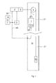
- Figure 1 represents an elevator system, which comprises an elevator car 1 and a counterweight 20 fitted to move vertically along guide rails in an elevator shaft 19. Elevator car travels in elevator shaft 19 between stopping floors according to service requests from call-giving devices.
- An elevator control unit 7 is operable to process the service requests and calculate a target speed for movement of the elevator car 1.
- An electric drive unit is mounted near top end of elevator shaft 19.
- the electric drive unit includes a hoisting machine 6 having a permanent magnet motor and a traction sheave mounted to the axis of the permanent magnet motor, as well as a frequency converter 2 connected to the stator of the permanent magnet motor for supplying power to the electric motor.
- the elevator car 1 and the counterweight 20 are suspended with a hoisting roping 21.
- the hoisting roping 21 runs via traction sheave of the hoisting machine 6.
- Permanent magnet motor drives the traction sheave causing elevator car 1 and counterweight 20 to move in opposite directions in elevator shaft 19.
- the electric drive unit is disposed in elevator shaft pit.
- the elevator system has a hoisting roping, which is coupled to the hoisting machine disposed in the pit.
- the elevator system has further a suspension roping which is coupled to at least one pulley near top end of the shaft 19.
- Hoisting machine drives elevator car / counterweight by pulling the hoisting roping, whereas the suspension roping only suspends elevator car / counterweight such that no pulling force is applied to it with the hoisting machine.
- rope is understood to refer to traditional circular ropes as well as belts, which ropes / belts may be manufactured of any suitable materials such as steel wires, synthetic fibers, polyurethane etc.
- the electric drive unit is disposed in a machine room separate from the shaft 19.
- the elevator according to the disclosure may also be implemented without a counterweight.
- the elevator of figure 1 is so called “passenger goods elevator", which means it is suitable for hoisting cargo also.
- the car 1, car frame, safety gear, guide rails and hoisting machine brakes are dimensioned such that a truck or corresponding cargo loading equipment may enter inside the elevator car.
- the electric drive unit (hoisting machine 6 plus frequency converter 2) of the elevator is dimensioned to drive the cargo only, thus it is not capable of hoisting the additional cargo loading equipment.
- the elevator system of figure 1 contains a load monitor, which is implemented as a reciprocal monitor of the elevator car load. Operation and construction of the load monitor is disclosed hereinafter.
- the load monitor has two independent measuring devices 3, 3', 3" for measuring elevator load weight 4. Many different kind of measuring devices may be used in this respect, but the measuring devices 3, 3', 3" used must be independent of each other, e.g. change or malfunction of one measuring device does not affect operation of the other measuring device, and vice versa.
- the measuring device is a strain gauge associated with the elevator car 1.
- the strain gauge 3 is coupled to the elevator car 1 floor to measure floor depression caused by weight of load inside the elevator car 1.
- the strain gauge 3" is coupled to hoisting roping 21 to measure tension of the roping, which changes as the amount of load inside elevator 1 car changes.
- the measuring device is a current sensor 3' adapted to measure stator current of the permanent magnet motor of the hoisting machine 6.
- stator current is directly proportional to motor torque.
- the weight of load can also be determined from the stator current.
- the current sensor 3' is in the main circuit of the frequency converter 2 and it functions as a part of the current control loop during normal operation of the frequency converter 2.
- the load monitor also comprises a computer-based safety control unit 5.
- the safety control unit 5 is connected to elevator car 1 interface unit 22 via a data bus 8A.
- Safety control unit 5 receives from the car interface unit 22 via data bus 8A measurement data from strain gauge 3, 3" associated with the elevator car 1.
- This data represents a first elevator load weight information (information about load inside elevator car 1).
- Safety control unit 5 is further connected to the frequency converter 2 via a second data bus 8B.
- Safety control unit 5 receives measurement data of the current sensor 3' from data bus 8B.
- Safety control unit 5 also receives from the elevator control unit 7 information of elevator operation state.
- the safety control unit 5 also converts the current sensor 3' data to express the weight of the compensated load such that it corresponds to the first elevator load weight information. This converted data represents a second elevator load weight information.
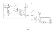
- Safety control unit 5 further includes a software-implemented comparator 9, see figure 2 .
- Output 12 of the comparator 9 controls a safety relay 13, which is connected to elevator safety chain 14, such that safety chain can be selectively opened or closed based on the comparison result from the comparator 9.
- opening of the safety chain 14 causes interruption of power supply to the hoisting machine 6 as well as closing of the hoisting machine brakes 16 to brake the traction sheave, therefore elevator operation can be selectively allowed or blocked based on the comparison result.
- safety chain also other kind of elevator safety configuration may be adopted, but the basic safety operation principle remains, e.g. blocking of elevator operation by interrupting power supply to the hoisting machine 6 as well as closing the hoisting machine brakes 16.
- the comparator 9 is configured to compare the first elevator load weight information 10 received from strain gauge 3, 3" in elevator car 1 with the second elevator load weight information 10' received from current sensor 3' of frequency converter 2.
- the safety control unit 5 comprises a memory into which a first comparator threshold value 11 is stored.
- the comparator 9 creates for elevator service function a request for calibration of the measuring device 3, 3', 3" if the deviation between the first elevator load weight information 10 and the second elevator load weight information 10' exceeds the first comparator threshold value 11.
- the calibration request is represented on a display of manual user interface 18.
- the calibration request is sent to a service center via a remote link.
- Calibration takes place by inputting via the manual user interface 18 in kilograms the amount of load 4 inside the elevator car 1. Said load amount information is sent from elevator control unit 7 to the safety control unit 5. The safety control unit 5 then associates the inputted load amount information with the data received from the measuring devices 3, 3', 3". This action may also be repeated with couple of different loads measuring values to improve the calibration result.
- the memory of the safety control unit 5 further includes a second comparator threshold value 11' stored therein, which second comparator threshold value 11' is greater that the first comparator threshold value 11. If the deviation between the first elevator load weight information 10 and the second elevator load information 10' further exceeds the second comparator threshold value 11', the comparator 9 outputs a comparison result 12 that causes opening of the safety chain 14 and therefore blocking of further elevator operation. Elevator doors are also opened and elevator users are instructed of the detectedd failure. Further, in some embodiments failure information is sent to the remote service center via the remote link.
- the safety control unit also 5 includes an overload limit 17, which is stored in the memory.
- the software-implemented comparator 9' of the safety control unit 5 compares the first and / or the second elevator load weight information 10, 10' to the overload limit 17. If at least one of the first 10 and the second 10' elevator load weight information exceeds the overload limit 17, the safety control unit detects an overload situation and blocks elevator operation by opening the safety chain 14 and keeping it open. Additionally, elevator users are instructed of the detected overload situation. Elevator operation is not allowed until the overload situation is removed, by removing the loading equipment from elevator car 1, removing some of the cargo 4 from elevator car 1 etc..
- two independent strain gauges 3, 3' are used as measuring devices instead of combination of a strain gauge 3, 3" and a current sensor 3'. This means that comparison of the load weight information 10, 10' is possible without opening the machinery brakes 16.
- the strain gauge 3, 3" measuring elevator load can also be disposed in some other location.
- at least one strain gauge 3, 3" is fitted in connection with a rope clamp of the hoisting roping 21.
- at least one strain gauge is fitted in connection with one or more machinery brakes 16 for measuring the braking force of the machinery brake(s) 16. Said braking force corresponds to the weight of load inside the elevator car 1, thus the weight of load can be determined from said braking force.
- the safety control unit 5 disclosed may also include functionality other than the load monitor.
- the safety control unit 5 may be a separate device or it may be combined with some other elevator device, such as the elevator control unit 7 or the frequency converter 2.
Landscapes
- Elevator Control (AREA)
- Maintenance And Inspection Apparatuses For Elevators (AREA)
Abstract
Description
- The invention relates to solutions for controlling elevator safety.
- An elevator system may comprise an elevator car operable to move vertically inside an elevator shaft between stopping floors. An electric drive unit may be adopted to drive the elevator car. The drive unit may include a hoisting machine having an electric motor and a traction sheave mounted to the axis of the electric motor, as well as a power converter for supplying power to the electric motor. The elevator car may be coupled to the rotation of the traction sheave via a hoisting roping, such that elevator car moves when the electric motor drives the traction sheave.
- Elevator cars are commonly used for hoisting cargo. In this context specific loading equipment (truck etc.) is often needed to move the cargo to inside the elevator car and also to remove the hoisted cargo afterwards from the elevator car. Sometimes loading / unloading of the car also requires the loading equipment to enter inside the elevator car, in which case it has to be assured that elevator system is dimensioned to carry the extra weight of the loading equipment also.
- There is a general need of designing an elevator system such that in can be fitted into a limited space of the building. To achieve this, size of the elevator components, such as the electric drive unit should be minimized.
- It is objective of this invention to introduce a solution which enables downsizing of the drive unit, in particular in elevators useful for hoisting cargo. Therefore the invention discloses an elevator system according to
claim 1 and a method according toclaim 12. Some preferred embodiments of the invention are described in the dependent claims. Some inventive embodiments, as well as inventive combinations of various embodiments are presented in the descriptive section and in the drawings of the present application. - An aspect of the invention is an elevator system, comprising an elevator car, an electric drive unit for driving the elevator car, a first measuring device for measuring elevator load weight and also a second measuring device for measuring elevator load weight, the second measuring device being independent of the first measuring device. The elevator system further comprises a safety control unit associated with the drive unit. The safety control unit comprises an input channel for receiving a first elevator load weight information from the first measuring device, an input channel for receiving a second elevator load weight information from the second measuring device and a comparator configured to compare the first elevator load weight information with the second elevator load weight information and to output a comparison result. The safety control unit is configured to selectively allow or block elevator operation based on the comparison result.
- Another aspect of the invention is a method of supervising elevator safety, the method comprising measuring with a first measuring device a first elevator load weight information, measuring with a second measuring device a second elevator load weight information, comparing the first elevator load weight information with the second elevator load weight information, and if the first elevator load weight information deviates from the second elevator load weight information more than is a preset threshold, then blocking elevator operation.
- This means that presence / absence of loading equipment inside the elevator car can always be monitored with increased level of safety. Therefore it can be assured that loading equipment has left elevator car before a new elevator run is allowed. This leads to an advantage that the elevator drive unit may be dimensioned according to rated weight of cargo without having to take into consideration weight of the loading equipment (truck etc.).
- The sentence "the second measuring device being independent of the first measuring device" means that a change or malfunction in the first measuring device does not affect operation of the second measuring device, and vice versa.
- In the disclosure the term "elevator load" means a load affecting rope tension distribution in the hoisting roping, at opposite sides of traction sheave. Such load may be cargo loaded inside an elevator car. The weight of said load (load weight) may be measured for example with a pressure sensor of elevator car floor, strain gauge measuring depression of elevator car floor or tension of hoisting roping, or a current sensor measuring motor current required to keep elevator car immovable while brakes open.
- According to an embodiment, the elevator car is operable to transfer cargo from start floor to destination floor.
- According to an embodiment, the safety control unit comprises a memory for setting a first comparator threshold value, and that the comparator is configured to create a request for calibration of the measuring device if the deviation between the first elevator load weight information and the second elevator load weight information exceeds the first comparator threshold value.
- According to an embodiment, the memory is for setting also a second comparator threshold value, the second comparator threshold value being greater that the first comparator threshold value, and that the comparator is configured to block elevator operation if the deviation between the first elevator load weight information and the second elevator load weight information further exceeds the second comparator threshold value.
- According to an embodiment, the safety control unit includes an overload limit, and the safety control unit is configured to block elevator operation if at least one of the first and the second elevator load weight information exceeds the overload limit. According to an embodiment, the first measuring device is associated with the elevator car.
- According to an embodiment, the second measuring device is associated with the drive unit.
- According to an embodiment, the elevator system comprises a user interface for inputting weight information of the load inside the elevator car, the user interface being in communicative connection with the safety control unit. The safety control unit is configured to associate the inputted weight information with elevator load weight information issued by the first and / or the second measuring device, for calibrating said measuring device.
- According to an embodiment, if the first elevator load weight information is similar to the second elevator load weight information within the preset threshold, then allowing elevator operation.
- According to an embodiment, the safety control unit is configured to convert at least one of the first and the second elevator load weight information such that they both refer to a same physical quantity. This means that the corresponding load weight information is / are converter before being compared in the comparator.
- According to an embodiment, comparing at least one of the first elevator load weight information and the second elevator load weight information to an overload limit, and if said at least one of the first elevator load weight information and the second elevator load weight information exceeds the overload limit, then blocking elevator operation.
- The preceding summary, as well as the additional features and additional advantages of the invention presented below, will be better understood by the aid of the following description of some embodiments, said description not limiting the scope of application of the invention.
-
- Fig. 1
- represents as a schematic diagram of an elevator system according to the disclosure.
- Fig. 2
- presents some functional elements of the safety control unit in the elevator system of
figure 1 . - Figs. 3a, 3b
- present some control parameters of the of
fig. 2 safety control unit. - For the sake of intelligibility, in
figs 1 - 3 only those features are represented which are deemed necessary for understanding the invention. Therefore, for instance, certain components / functions which are widely known to be present in corresponding art may not be represented. - In the description same references are always used for same items.
-
Figure 1 represents an elevator system, which comprises anelevator car 1 and acounterweight 20 fitted to move vertically along guide rails in anelevator shaft 19. Elevator car travels inelevator shaft 19 between stopping floors according to service requests from call-giving devices. Anelevator control unit 7 is operable to process the service requests and calculate a target speed for movement of theelevator car 1. An electric drive unit is mounted near top end ofelevator shaft 19. The electric drive unit includes a hoistingmachine 6 having a permanent magnet motor and a traction sheave mounted to the axis of the permanent magnet motor, as well as afrequency converter 2 connected to the stator of the permanent magnet motor for supplying power to the electric motor. Theelevator car 1 and thecounterweight 20 are suspended with a hoistingroping 21. The hoisting roping 21 runs via traction sheave of the hoistingmachine 6. Permanent magnet motor drives the traction sheave causingelevator car 1 andcounterweight 20 to move in opposite directions inelevator shaft 19. - In some embodiments, the electric drive unit is disposed in elevator shaft pit. The elevator system has a hoisting roping, which is coupled to the hoisting machine disposed in the pit. The elevator system has further a suspension roping which is coupled to at least one pulley near top end of the
shaft 19. Hoisting machine drives elevator car / counterweight by pulling the hoisting roping, whereas the suspension roping only suspends elevator car / counterweight such that no pulling force is applied to it with the hoisting machine. - The term "roping" is understood to refer to traditional circular ropes as well as belts, which ropes / belts may be manufactured of any suitable materials such as steel wires, synthetic fibers, polyurethane etc.
- In some embodiments the electric drive unit is disposed in a machine room separate from the
shaft 19. - The elevator according to the disclosure may also be implemented without a counterweight.
- The elevator of
figure 1 is so called "passenger goods elevator", which means it is suitable for hoisting cargo also. Thecar 1, car frame, safety gear, guide rails and hoisting machine brakes are dimensioned such that a truck or corresponding cargo loading equipment may enter inside the elevator car. - On the other hand, for space-saving purposes and to reduce costs the electric drive unit (hoisting
machine 6 plus frequency converter 2) of the elevator is dimensioned to drive the cargo only, thus it is not capable of hoisting the additional cargo loading equipment. - To make sure that elevator run does not start as long as the cargo loading equipment is still inside the
elevator car 1, the elevator system offigure 1 contains a load monitor, which is implemented as a reciprocal monitor of the elevator car load. Operation and construction of the load monitor is disclosed hereinafter. - The load monitor has two
independent measuring devices measuring devices elevator car 1. In an embodiment thestrain gauge 3 is coupled to theelevator car 1 floor to measure floor depression caused by weight of load inside theelevator car 1. In an embodiment thestrain gauge 3" is coupled to hoistingroping 21 to measure tension of the roping, which changes as the amount of load insideelevator 1 car changes. Further, in some embodiments the measuring device is a current sensor 3' adapted to measure stator current of the permanent magnet motor of the hoistingmachine 6. In the permanent magnet motor offigure 1 , stator current is directly proportional to motor torque. Further, because the motor torque corresponds to the weight of load inside theelevator car 1, the weight of load can also be determined from the stator current. In a preferred embodiment the current sensor 3' is in the main circuit of thefrequency converter 2 and it functions as a part of the current control loop during normal operation of thefrequency converter 2. - The load monitor also comprises a computer-based
safety control unit 5. As represented infigure 1 , thesafety control unit 5 is connected toelevator car 1interface unit 22 via adata bus 8A.Safety control unit 5 receives from thecar interface unit 22 viadata bus 8A measurement data fromstrain gauge elevator car 1. This data represents a first elevator load weight information (information about load inside elevator car 1). -
Safety control unit 5 is further connected to thefrequency converter 2 via asecond data bus 8B.Safety control unit 5 receives measurement data of the current sensor 3' fromdata bus 8B.Safety control unit 5 also receives from theelevator control unit 7 information of elevator operation state. Whensafety control unit 5 registers a request for starting a new elevator run, it reads fromfrequency converter 2 current sensor data representing stator current required to keep elevator car immovable after machine brakes are opened. This data is directly proportional to torque required to compensate weight of load insideelevator car 1. Thesafety control unit 5 also converts the current sensor 3' data to express the weight of the compensated load such that it corresponds to the first elevator load weight information. This converted data represents a second elevator load weight information. -
Safety control unit 5 further includes a software-implemented comparator 9, seefigure 2 .Output 12 of the comparator 9 controls asafety relay 13, which is connected toelevator safety chain 14, such that safety chain can be selectively opened or closed based on the comparison result from the comparator 9. As is known, opening of thesafety chain 14 causes interruption of power supply to the hoistingmachine 6 as well as closing of the hoistingmachine brakes 16 to brake the traction sheave, therefore elevator operation can be selectively allowed or blocked based on the comparison result. Instead of safety chain also other kind of elevator safety configuration may be adopted, but the basic safety operation principle remains, e.g. blocking of elevator operation by interrupting power supply to the hoistingmachine 6 as well as closing the hoistingmachine brakes 16. - Operation principle of the comparator 9 is further illustrated in
figures 3a and 3b . The comparator 9 is configured to compare the first elevatorload weight information 10 received fromstrain gauge elevator car 1 with the second elevator load weight information 10' received from current sensor 3' offrequency converter 2. Thesafety control unit 5 comprises a memory into which a firstcomparator threshold value 11 is stored. The comparator 9 creates for elevator service function a request for calibration of the measuringdevice load weight information 10 and the second elevator load weight information 10' exceeds the firstcomparator threshold value 11. In some embodiments the calibration request is represented on a display ofmanual user interface 18. In some embodiments the calibration request is sent to a service center via a remote link. - Calibration takes place by inputting via the
manual user interface 18 in kilograms the amount of load 4 inside theelevator car 1. Said load amount information is sent fromelevator control unit 7 to thesafety control unit 5. Thesafety control unit 5 then associates the inputted load amount information with the data received from the measuringdevices - The memory of the
safety control unit 5 further includes a second comparator threshold value 11' stored therein, which second comparator threshold value 11' is greater that the firstcomparator threshold value 11. If the deviation between the first elevatorload weight information 10 and the second elevator load information 10' further exceeds the second comparator threshold value 11', the comparator 9 outputs acomparison result 12 that causes opening of thesafety chain 14 and therefore blocking of further elevator operation. Elevator doors are also opened and elevator users are instructed of the detectedd failure. Further, in some embodiments failure information is sent to the remote service center via the remote link. - The safety control unit also 5 includes an
overload limit 17, which is stored in the memory. The software-implemented comparator 9' of thesafety control unit 5 compares the first and / or the second elevatorload weight information 10, 10' to theoverload limit 17. If at least one of the first 10 and the second 10' elevator load weight information exceeds theoverload limit 17, the safety control unit detects an overload situation and blocks elevator operation by opening thesafety chain 14 and keeping it open. Additionally, elevator users are instructed of the detected overload situation. Elevator operation is not allowed until the overload situation is removed, by removing the loading equipment fromelevator car 1, removing some of the cargo 4 fromelevator car 1 etc.. - In some embodiments, two
independent strain gauges 3, 3' are used as measuring devices instead of combination of astrain gauge load weight information 10, 10' is possible without opening themachinery brakes 16. - The
strain gauge strain gauge roping 21. In some embodiments, at least one strain gauge is fitted in connection with one ormore machinery brakes 16 for measuring the braking force of the machinery brake(s) 16. Said braking force corresponds to the weight of load inside theelevator car 1, thus the weight of load can be determined from said braking force. - The
safety control unit 5 disclosed may also include functionality other than the load monitor. Thesafety control unit 5 may be a separate device or it may be combined with some other elevator device, such as theelevator control unit 7 or thefrequency converter 2. - The invention is described above by the aid of a few examples of its embodiment. It is obvious to the person skilled in the art that the invention is not only limited to the embodiments described above, but that many other applications are possible within the scope of the inventive concept defined by the claims.
Claims (15)
- An elevator system, comprising:an elevator car (1);a drive unit (2, 6) configured to drive the elevator car (1);a first measuring device (3) for measuring elevator load weight (4);characterized in that the elevator system comprises:a second measuring device (3', 3") for measuring elevator load weight (4), the second measuring device (3', 3") being independent of the first measuring device (3);a safety control unit (5) associated with the drive unit (2, 6), the safety control unit (5) comprising:an input channel (8A) for receiving a first elevator load weight information (10) from the first measuring device (3);an input channel (8B) for receiving a second elevator load weight information (10') from the second measuring device (3', 3");a comparator (9) configured to compare the first elevator load weight information (10) with the second elevator load weight information (10') and to output a comparison result (12);wherein the safety control unit (5) is configured to selectively allow or block elevator operation based on the comparison result (12).
- The elevator system according to claim 1, characterized in that the elevator car (1) is operable to transfer cargo (4) from start floor to destination floor.
- The elevator system according to claim 1 or 2, characterized in that the safety control unit (5) comprises a memory for setting a first comparator threshold value (11), and that the comparator (9) is configured to create a request for calibration of the measuring device (3, 3', 3") if the deviation between the first elevator load weight information (10) and the second elevator load weight information (10') exceeds the first comparator threshold value (11).
- The elevator system according to claim 3, characterized in that the memory is for setting also a second comparator threshold value (11'), the second comparator threshold value (11') being greater that the first comparator threshold value (11), and that the comparator (9) is configured to block elevator operation if the deviation between the first elevator load weight information (10) and the second elevator load information (10') further exceeds the second comparator threshold value (11').
- The elevator system according to any of the preceding claims, characterized in that the safety control unit (5) includes an overload limit (17);
and that the safety control unit (5) is configured to block elevator operation if at least one of the first (10) and the second (10') elevator load weight information exceeds the overload limit (17). - The elevator system according to any of the preceding claims, characterized in that the first measuring device (3) is associated with the elevator car.
- The elevator system according to any of the preceding claims, characterized in that the second measuring device (3') is associated with the drive unit (2, 6).
- The elevator system according to claim 7,characterized in that the second measuring device (3') is operable to measure a physical quantity representing elevator drive torque.
- The elevator system according to any of the preceding claims, characterized in that the elevator system comprises a user interface (18) for inputting weight information of the load (4) inside the elevator car (1), the user interface (18) being in communicative connection with the safety control unit (5);
and that the safety control unit (5) is configured to associate the inputted weight information with elevator load weight information issued by the first (3) and / or the second measuring device (3', 3"), for calibrating said measuring device (3, 3', 3"). - The elevator system according to any of the preceding claims, characterized in that the safety control unit is configured to convert at least one of the first (10) and the second (10') elevator load weight information such that they both refer to a same physical quantity.
- The elevator system according to any of the preceding claims, characterized in that the safety control unit (5) is configured to register a request for starting new elevator run, and in that the comparator (9) is configured to compare the first elevator load weight information (10) with the second elevator load weight information (10') and to output a comparison result responsive to safety control unit (5) registering a request for starting a new elevator run.
- A method of controlling elevator safety, the method comprising:- measuring with a first measuring device (3) a first elevator load weight information (10)characterized by:- measuring with a second measuring device (3', 3 ") a second elevator load weight information (10'),- comparing the first elevator load weight information (10) with the second elevator load weight information (10'), and- if the first elevator load weight information (10) deviates from the second elevator load weight information (10') more than is a preset threshold (11'), then blocking elevator operation.
- The method according to claim 12, characterized by:- if the first elevator load weight information (10) is similar to the second elevator load weight information (10') within the preset threshold (11'), then allowing elevator operation.
- The method according to claim 12 or 13, characterized by:- comparing at least one of the first elevator load weight information (10) and the second elevator load weight information (10') to an overload limit (17), and- if said at least one of the first elevator load weight information (10) and the second elevator load weight information (10') exceeds the overload limit (17), then blocking elevator operation.
- The method according to any of claims 12 - 14, characterized by:- polling for a request for starting a new elevator run- comparing the first elevator load weight information (10) with the second elevator load weight information (10') responsive to registering a request for starting a new elevator run.
Priority Applications (1)
| Application Number | Priority Date | Filing Date | Title |
|---|---|---|---|
| EP14185329.1A EP2998259A1 (en) | 2014-09-18 | 2014-09-18 | An elevator system and a method for controlling elevator safety |
Applications Claiming Priority (1)
| Application Number | Priority Date | Filing Date | Title |
|---|---|---|---|
| EP14185329.1A EP2998259A1 (en) | 2014-09-18 | 2014-09-18 | An elevator system and a method for controlling elevator safety |
Publications (1)
| Publication Number | Publication Date |
|---|---|
| EP2998259A1 true EP2998259A1 (en) | 2016-03-23 |
Family
ID=51584973
Family Applications (1)
| Application Number | Title | Priority Date | Filing Date |
|---|---|---|---|
| EP14185329.1A Withdrawn EP2998259A1 (en) | 2014-09-18 | 2014-09-18 | An elevator system and a method for controlling elevator safety |
Country Status (1)
| Country | Link |
|---|---|
| EP (1) | EP2998259A1 (en) |
Cited By (4)
| Publication number | Priority date | Publication date | Assignee | Title |
|---|---|---|---|---|
| CN114249198A (en) * | 2020-09-25 | 2022-03-29 | 通力股份公司 | Method for operating an elevator system and elevator system |
| CN115515878A (en) * | 2020-05-08 | 2022-12-23 | 因温特奥股份公司 | Method for operating a people conveyor by reliably configuring an electronic safety device |
| WO2023147839A1 (en) | 2022-02-01 | 2023-08-10 | Kone Corporation | Solution for controlling elevator safety |
| DE102023110190A1 (en) * | 2023-04-21 | 2024-10-24 | Tk Elevator Innovation And Operations Gmbh | Method for braking a step or pallet belt of a passenger transport system |
Citations (6)
| Publication number | Priority date | Publication date | Assignee | Title |
|---|---|---|---|---|
| JPH1111817A (en) * | 1997-06-23 | 1999-01-19 | Hitachi Building Syst Co Ltd | Diagnosis device for hydraulic elevator scale device |
| DE102004058756A1 (en) * | 2004-12-06 | 2006-06-14 | Siemens Ag | Speed monitoring method in an automation system for a conveyor system |
| EP2022742A1 (en) * | 2007-08-07 | 2009-02-11 | ThyssenKrupp Elevator AG | Lift system |
| WO2009073025A1 (en) * | 2007-12-05 | 2009-06-11 | Otis Elevator Company | Control strategy for operating two elevator cars in a single hoistway |
| US20090314584A1 (en) * | 2008-06-19 | 2009-12-24 | Smith Rory S | Rope Tension Equalizer and Load Monitor |
| WO2013115827A1 (en) * | 2012-02-03 | 2013-08-08 | Otis Elevator Company | System and method for reducing speed of an elevator car |
-
2014
- 2014-09-18 EP EP14185329.1A patent/EP2998259A1/en not_active Withdrawn
Patent Citations (6)
| Publication number | Priority date | Publication date | Assignee | Title |
|---|---|---|---|---|
| JPH1111817A (en) * | 1997-06-23 | 1999-01-19 | Hitachi Building Syst Co Ltd | Diagnosis device for hydraulic elevator scale device |
| DE102004058756A1 (en) * | 2004-12-06 | 2006-06-14 | Siemens Ag | Speed monitoring method in an automation system for a conveyor system |
| EP2022742A1 (en) * | 2007-08-07 | 2009-02-11 | ThyssenKrupp Elevator AG | Lift system |
| WO2009073025A1 (en) * | 2007-12-05 | 2009-06-11 | Otis Elevator Company | Control strategy for operating two elevator cars in a single hoistway |
| US20090314584A1 (en) * | 2008-06-19 | 2009-12-24 | Smith Rory S | Rope Tension Equalizer and Load Monitor |
| WO2013115827A1 (en) * | 2012-02-03 | 2013-08-08 | Otis Elevator Company | System and method for reducing speed of an elevator car |
Cited By (5)
| Publication number | Priority date | Publication date | Assignee | Title |
|---|---|---|---|---|
| CN115515878A (en) * | 2020-05-08 | 2022-12-23 | 因温特奥股份公司 | Method for operating a people conveyor by reliably configuring an electronic safety device |
| CN114249198A (en) * | 2020-09-25 | 2022-03-29 | 通力股份公司 | Method for operating an elevator system and elevator system |
| EP3974367A1 (en) * | 2020-09-25 | 2022-03-30 | KONE Corporation | Method of calibraring a load weighing device of an elevator system and elevator system |
| WO2023147839A1 (en) | 2022-02-01 | 2023-08-10 | Kone Corporation | Solution for controlling elevator safety |
| DE102023110190A1 (en) * | 2023-04-21 | 2024-10-24 | Tk Elevator Innovation And Operations Gmbh | Method for braking a step or pallet belt of a passenger transport system |
Similar Documents
| Publication | Publication Date | Title |
|---|---|---|
| US10179718B2 (en) | Elevator car overload monitoring to prevent starting | |
| US7222698B2 (en) | Elevator arrangement | |
| AU2013200557B2 (en) | Method for controlling an elevator, and an elevator | |
| EP2537790B1 (en) | Elevator device | |
| CN105026297B (en) | For the method and apparatus for the security for monitoring counter weight type elevator | |
| CN108455396B (en) | Elevator safety system and method for monitoring an elevator system | |
| CN104176576B (en) | Attached elevator with safety device | |
| JP2011042480A (en) | Elevator device | |
| KR102065518B1 (en) | Elevator device | |
| JP6058160B2 (en) | Elevator apparatus and control method thereof | |
| JP5326474B2 (en) | Elevator rope slip detection device and elevator device using the same | |
| JP4079886B2 (en) | Elevator emergency stop test equipment | |
| KR101487623B1 (en) | Traction force measuring method of an elevator | |
| JP5098376B2 (en) | Elevator control device | |
| CN113548560B (en) | Method for testing safety characteristics of an elevator | |
| JP5026078B2 (en) | Elevator equipment | |
| CN100522781C (en) | Control system of elevator | |
| JP5791490B2 (en) | Elevator emergency stop device and elevator emergency stop method | |
| JP5829869B2 (en) | Elevator emergency stop device | |
| KR20170011241A (en) | Braking force test method of elevator double brake | |
| CN109956381B (en) | Safety elevator system | |
| KR100871514B1 (en) | Elevator control system | |
| KR20070024560A (en) | Elevator control system | |
| CN117466092A (en) | Elevator brake braking force monitoring method and device | |
| CN108726332B (en) | Method and apparatus for determining transmission efficiency of elevator traction system |
Legal Events
| Date | Code | Title | Description |
|---|---|---|---|
| PUAI | Public reference made under article 153(3) epc to a published international application that has entered the european phase |
Free format text: ORIGINAL CODE: 0009012 |
|
| AK | Designated contracting states |
Kind code of ref document: A1 Designated state(s): AL AT BE BG CH CY CZ DE DK EE ES FI FR GB GR HR HU IE IS IT LI LT LU LV MC MK MT NL NO PL PT RO RS SE SI SK SM TR |
|
| AX | Request for extension of the european patent |
Extension state: BA ME |
|
| 17P | Request for examination filed |
Effective date: 20160921 |
|
| RBV | Designated contracting states (corrected) |
Designated state(s): AL AT BE BG CH CY CZ DE DK EE ES FI FR GB GR HR HU IE IS IT LI LT LU LV MC MK MT NL NO PL PT RO RS SE SI SK SM TR |
|
| GRAP | Despatch of communication of intention to grant a patent |
Free format text: ORIGINAL CODE: EPIDOSNIGR1 |
|
| INTG | Intention to grant announced |
Effective date: 20170105 |
|
| STAA | Information on the status of an ep patent application or granted ep patent |
Free format text: STATUS: THE APPLICATION IS DEEMED TO BE WITHDRAWN |
|
| 18D | Application deemed to be withdrawn |
Effective date: 20170516 |