EP2998245A1 - Vibratory conveyor - Google Patents
Vibratory conveyor Download PDFInfo
- Publication number
- EP2998245A1 EP2998245A1 EP15157055.3A EP15157055A EP2998245A1 EP 2998245 A1 EP2998245 A1 EP 2998245A1 EP 15157055 A EP15157055 A EP 15157055A EP 2998245 A1 EP2998245 A1 EP 2998245A1
- Authority
- EP
- European Patent Office
- Prior art keywords
- conveyor
- arms
- vibratory
- vibrating conveyor
- rotation
- Prior art date
- Legal status (The legal status is an assumption and is not a legal conclusion. Google has not performed a legal analysis and makes no representation as to the accuracy of the status listed.)
- Granted
Links
Images








Classifications
-
- B—PERFORMING OPERATIONS; TRANSPORTING
- B65—CONVEYING; PACKING; STORING; HANDLING THIN OR FILAMENTARY MATERIAL
- B65G—TRANSPORT OR STORAGE DEVICES, e.g. CONVEYORS FOR LOADING OR TIPPING, SHOP CONVEYOR SYSTEMS OR PNEUMATIC TUBE CONVEYORS
- B65G27/00—Jigging conveyors
- B65G27/10—Applications of devices for generating or transmitting jigging movements
- B65G27/28—Applications of devices for generating or transmitting jigging movements with provision for dynamic balancing
- B65G27/30—Applications of devices for generating or transmitting jigging movements with provision for dynamic balancing by means of an oppositely-moving mass, e.g. a second conveyor
-
- B—PERFORMING OPERATIONS; TRANSPORTING
- B65—CONVEYING; PACKING; STORING; HANDLING THIN OR FILAMENTARY MATERIAL
- B65G—TRANSPORT OR STORAGE DEVICES, e.g. CONVEYORS FOR LOADING OR TIPPING, SHOP CONVEYOR SYSTEMS OR PNEUMATIC TUBE CONVEYORS
- B65G27/00—Jigging conveyors
- B65G27/04—Load carriers other than helical or spiral channels or conduits
-
- B—PERFORMING OPERATIONS; TRANSPORTING
- B65—CONVEYING; PACKING; STORING; HANDLING THIN OR FILAMENTARY MATERIAL
- B65G—TRANSPORT OR STORAGE DEVICES, e.g. CONVEYORS FOR LOADING OR TIPPING, SHOP CONVEYOR SYSTEMS OR PNEUMATIC TUBE CONVEYORS
- B65G27/00—Jigging conveyors
- B65G27/08—Supports or mountings for load-carriers, e.g. framework, bases, spring arrangements
-
- B—PERFORMING OPERATIONS; TRANSPORTING
- B65—CONVEYING; PACKING; STORING; HANDLING THIN OR FILAMENTARY MATERIAL
- B65G—TRANSPORT OR STORAGE DEVICES, e.g. CONVEYORS FOR LOADING OR TIPPING, SHOP CONVEYOR SYSTEMS OR PNEUMATIC TUBE CONVEYORS
- B65G27/00—Jigging conveyors
- B65G27/10—Applications of devices for generating or transmitting jigging movements
- B65G27/16—Applications of devices for generating or transmitting jigging movements of vibrators, i.e. devices for producing movements of high frequency and small amplitude
- B65G27/18—Mechanical devices
- B65G27/20—Mechanical devices rotating unbalanced masses
Definitions
- the invention relates to the field of vibratory conveyors, feeders and vibrating screens.
- Vibratory conveyors are widely used for material handling applications such as conveying, feeding or screening particulate materials.
- a longitudinally-extending material-conveying deck, tray or trough is supported on leaf or coil springs mounted on a base which itself is fixed or may be spring-mounted.
- a motor-driven eccentric drive device or other source of vibration imparts vibratory movement to the deck or tray, which vibration is maintained by the leaf or coil springs connected to the base. The vibratory movement of the deck or tray conveys the particulate material on the deck surface.
- the present invention provides a simple economical design to achieve a balanced vibrating conveyor or similar apparatus by using a common spring and rocker arm for conveyor trough and balancing weight.
- the design provides synchronized 180° out of phase vibrations of trough and balancing weight at all frequencies as well as balance at variable stroke lengths.
- the present invention provides a vibratory conveyor comprising a frame, and a source of vibratory force for providing vibratory movement to a conveying surface, the conveying surface being pivotally attached to a counterweight element by a plurality of rocker arms, each rocker arm being mounted on the frame for pivoting motion about the central axis of one end of a torsion spring element to which it is fixed, the second end of the torsion spring element being fixed to the frame.
- the rocker arms are arranged in opposed pairs, with a first rocker arm in the pair being mounted on a first side of the frame for pivoting motion about the central axis of one end of a first torsion spring element to which it is fixed, the second end of the torsion spring element being fixed to the opposite side of the frame, and a second rocker arm in the pair being mounted on the opposite side of the frame for pivoting motion about the central axis of one end of a second torsion spring element to which it is fixed, the second end of the torsion spring element being fixed to the first side of the frame.
- Torsion bars or torsional bushings may be provided as the torsion spring element.
- the present invention further provides a method of conveying material comprising i) providing a vibratory conveyor comprising a frame, and a source of vibratory force for providing vibratory movement to a conveying surface, the conveying surface being pivotally attached to a counterweight element by a plurality of rocker arms, each rocker arm being mounted on the frame for pivoting motion about the central axis of one end of a torsion spring element to which it is fixed, the second end of the torsion spring element being fixed to the frame; ii) applying vibratory movement to the conveying surface and thereby applying corresponding vibratory movement to the counterweight element until a steady state oscillation is reached; and iii) either before or after step ii) transferring the material to or placing the material on the conveying surface.
- a vibratory conveyor 10 having a flow direction as shown has a conveying trough 12, connected to base 14 and pivoting counterweight 16 by rocker arms 18 arranged in pairs on each side of trough 12.
- Motor 20 drives drive wheel 22 through drive belt 24.
- drive wheel 22 has an eccentric axle 26 which transmits a vibratory motion to trough 12 through connecting arm 28 and coil spring 30 which is connected to trough 12 through flange 31.
- Other forms of a flexible connection could be used instead of coil spring 30, such as a rubber connector.
- Base 14 is raised off a supporting surface 33 by a number of legs 32.
- a lower trough 34 connected to counterweight 16 may also be used as an additional counterweight while forming a lower conveyor used to convey materials.
- Trough 12 has an inner surface 13 which may be perforated, as further described below in reference to Fig. 13-15 , to screen particles which fall through to trough 34 to act as a lower conveyor to convey the screened material.
- each rocker arm 18 is pivotally connected at its upper end to trough 12 on axle 36 which is journaled in rocker arm 18 in bushing 38.
- Axle 36 is fixed to trough 12 by bolt 40.
- Rocker arm 18 is pivotally connected at its lower end on axle 42 which is journaled in rocker arm 18 in bushing 44.
- Axle 42 is fixed to counterweight 16 by bolt 45.
- Weights 46 may be placed in counterweight pan 47 to match or fine tune the weight of the counterweight 16 to that of the trough 12.
- the center of rocker arm 18 is provided with a circular opening 52 for receiving the end of torsion bar 50.
- torsion bar 50 is secured fixedly in aperture 52 by a keyless shaft- hub friction connector 54 such as a B-LOCTM keyless shaft- hub friction connector.
- the other end of torsion bar 50 is secured fixedly in aperture 56 of flange 58 also by a keyless shaft/ hub friction connector 60 or by other suitable means.
- Flange 58 is secured to base 14 by bolts, welding or the like.
- Horizontal torsion bar 50 pivots in bushing 64 mounted in aperture 66 of flange 68 which is secured to base 14 by bolts, welding or the like.
- Transverse members 62 join the parallel longitudinal members 70 of base 14.
- Fig. 6 illustrates a preferred configuration in which a pair of torsion bars 50, 50' is mounted in each set of flanges 58, 68, each connected to a rocker arm 18, slightly offset to permit installation.
- Horizontal torsion bars 50 may be made of any suitable fatigue-resistant material and will vary depending on the application.
- a preferred form of torsion bars comprises spring steel cylindrical bars, and more preferably precision ground rounds such as C1045 or 4140HTSR, high carbon 5160H heat treated bars. Bars 50 should be free of any nicks or marks. Other suitable cylindrical bars of metal or other material may be used.
- horizontal torsion bars 50 are mounted half-way between the points of rotation of axles 36 and 42. By balancing the weight of the counterweight 16 to that of the loaded trough 12 this results in balancing of the vibratory forces transmitted through the base 14 to the supporting structure.
- the angle of attack A ( Fig.
- Fig. 5 is the angle of the rocker arms 18 from vertical. It can be varied to vary the speed of conveying by rotating the rocker arms around their node or stationary pivot point (which in Fig. 5 is the central axis of torsion bars 50) thereby changing their inclination. Suitable angles of attack have been found to be 30 degrees plus or minus 15 degrees. The direction of transport can be changed by rotating the rocker arms to the other side of a vertical line through their node or stationary pivot point. Angle B in Fig. 5 is the total angle through which the end of torsion bar 50 which is fixed in rocker arm 18 twists.
- a typical setup will see a displacement or twist of the end of torsion bar 50 of a few degrees from the rest position, for a total twist in a cycle of twice that angle.
- the stroke of the conveyor namely the horizontal displacement of the trough with each vibration at the steady state forced vibration frequency of torsion bars 50, is a function of the length of the rocker arm, the weight of the trough 12 and counterweight 16, the frequency of the vibration, the number and length and diameter of the torsion bars 50 and the modulus of elasticity of the torsion bars 50.
- the rocker arms also provide a vertical component of vibratory movement which in combination with the horizontal component causes the particulate material to be conveyed when in operation.
- torsion bars 50 having different diameters will be advisable, since the spring force of the bars 50 is a function of the diameter and length of the bars.
- Torsion bars having a variable or progressive spring rate can also be provided by varying the diameter of the torsion bar along the length of the bar.
- motor 20 is started and oscillatory motion is transmitted through flange 31 to trough 12.
- Such oscillatory motion causes rocker arms 18 to start to pivot about the central axes of torsion bars 50 at increasing angles of displacement until a steady state oscillation is reached at a smooth operational state, referred to herein as the "natural frequency" of torsion bars 50.
- the stationary pivot point about which the rocker arms pivot at their natural frequency is referred to as their "node”.
- Particulate material placed on surface 13 of trough 12 is then conveyed due to the vertical component of vibration accompanying the horizontal component of vibration.
- the lower trough 34 can be used as a second vibratory conveyor to transport material from another source or screened from the conveyor trough 12 above.
- the conveying speed may be varied by varying the frequency of vibration. This can be accomplished by varying the speed of motor 20. This can be done simply by use of a variable frequency drive to vary the frequency of the electric power provided to the motor 20. For example motor 20 may run at 1800 rpm with a 60 hertz frequency of the electric power provided. Using a variable frequency drive the speed of the motor can be increased or decreased by varying the electrical power above or below 60 hertz by varying the frequency drive. In turn this will vary the conveying speed.
- the frequency of the drive may alternatively be varied by the use of variable pitch belt sheaves or other variable- RPM arrangement.
- FIGS 7 and 8 illustrate an alternate embodiment in which torsion bars 50 are replaced with torsion bushings 80.
- the torsion bushing 80 has an outer cylindrical metal surface 88 which is welded to the rocker arm 18 and an inner cylindrical bushing surface 86 which is secured to flange 84 by bolt 82.
- the material 81 between surfaces 88 and 86 has a suitable degree of flexibility that it functions in the same way as the torsion bars 50.
- a suitable material for example is TDI polyester based polyurethane.
- Suitable torsion bushings are manufactured by Redwood Plastics.
- inner cylindrical bushing surface 86 of the torsion bushing 80 can be welded to the rocker arm 18 and the outer cylindrical metal surface 88 secured to flange 84.
- Similar torsion bushings can be provided at any one, or two or all of the pivot axes 83, 85, 87 of rocker arms 118.
- FIGS 9 and 10 illustrate an alternate embodiment of the conveyor 100 having two conveying troughs 104, 106 wherein the torsion bar 102 is located beneath the lower trough 106 in order to clear the space above the lower trough 106.
- the central axis 108 of rocker arms 18 pivots freely on central beam 114 which is fixed on legs 115 to base 116.
- the lower pivot point 110 of rocker arms 18 is fixed on one end of torsion bar 102 in the manner described above while the other end 111 of torsion bar 102 is fixed in flange 112, which in turn is connected to trough 106 by plate 107.
- Torsion bar 102 rotates in flange 113 which is secured to trough 106 by plate 109.
- Motor 20 can be mounted centrally of the conveyor lengthwise with springs 30 straddling either side of trough 106. Motor 20 can also be mounted towards either end of the conveyor. Similarly the torsion bars 102 can be located above trough 104 or at any one, or two or all of the pivot axes of rocker arms 18.
- Figures 11 and 12 illustrate an alternate embodiment of the conveyor 120 having a low profile to reduce the overall height of the machine.
- a single conveying trough 122 is provided and the torsion bar 124 is located beneath the conveying trough.
- the rocker arms have uneven lengths about the central pivot point 128. That is, the length C of the arm from the lower axis 126 to the central axis 128 is greater than the length D of the arm from the upper axis 130 to the central axis 128.
- the upper end of rocker arms 118 are pivotally connected to parallel longitudinal balance beams 132 by bolts 138 as described above. Balance beams 132 provide the upper counterweight during the oscillatory motion.
- Motor 20 can be mounted in the center of the conveyor lengthwise with springs 30 straddling either side of trough 122. Motor 20 can also be mounted towards either end of the conveyor.
- Figures 13 to 15 illustrate a design for the conveyor trough 150 with a slotted profiled screen horizontal support surface 152, in the case of a conveyor moving particles in the direction from right to left in Fig. 13 .
- This is an alternative to the inner surface 13 described above in respect of Fig. 2 which may be perforated to screen particles.
- a series of parallel transverse slotted apertures 154 is formed by transverse plates 158.
- a series of diverting bars 156 are secured to plates 158, the lower leading edge of bars 156 being welded to the upper surface of plates 158 and the upper trailing edge of bars 156 being welded to the lower surface of plates 158.
- Bars 156 are angled from the vertical on either side of the longitudinal center line of the trough at progressively greater angles as the distance from the center increases in order to fan out the material to prevent plugging.
- the larger conveyed pieces continue over plates 158 from right to left while the smaller screened pieces drop down through apertures 154.
- the diverting bars 156 therefore tend to spread the screened materials away from the center of the conveyor as it passes through apertures 154.
- Fig. 16 through 19 illustrate a second embodiment of the vibratory drive which is springless.
- Motor 20 as in Fig. 1 drives sheave 216 through drive belt 24.
- Sheave 216 is mounted on an eccentric shaft 214 which rotates in bearing 223 and transmits a vibratory motion to rocker arms 18 through drive arms 226, 227 as described below.
- the ends of rocker arms 18 are pivotally connected to the conveyor troughs on bushings 210 as previously described.
- a balancing weight 213 is attached to shaft 214 by a hub 212 and lock assembly 234 in order to assist in balancing the drive system by countering the offset of eccentric shaft 214.
- Drive arms 226, 227 are journaled at one end on shaft 214 for rotation on bearings 222 and pivotally connected at the other end 219 to torsion arms 215.
- one of the drive arms 226 is shorter than the other 227.
- Torsion arms 215 are locked at their upper end on torsion bars 50 by lock assembly 235 adjacent the flanges 228 in which the end of torsion bar 50 is free to rotate in bushing 227.
- the other end of torsion bar 50 is locked in the central axis of rocker arm 18 by lock assembly 236. In this way the drive provides a vibratory motion directly to torsion bars 50 which is communicated to the rocker arms 18 and thence to the conveyor.
- the vibrating conveyor systems described above can be applied generally to vibratory feeders as well as to vibrating screens whereby the angle of attack of the rocker arms can be selected to reduce the amount of conveying movement.
- the present invention therefore provides a vibratory conveyor comprising a frame, and a source of vibratory force mounted on a suitable location for providing vibratory movement to a conveying surface, the conveying surface being pivotally attached to a counterweight element by a plurality of rocker arms, each rocker arm being mounted on the frame for pivoting motion about the central axis of one end of a torsion spring element to which it is fixed, the second end of the torsion spring element being fixed to the frame.
- the rocker arms are arranged in opposed pairs, with a first rocker arm in the pair being mounted on a first side of the frame for pivoting motion about the central axis of one end of a first torsion spring element to which it is fixed, the second end of the torsion spring element being fixed to the opposite side of the frame, and a second rocker arm in the pair being mounted on the opposite side of the frame for pivoting motion about the central axis of one end of a second torsion spring element to which it is fixed, the second end of the torsion spring element being fixed to the first side of the frame.
- Alternatively other arrangements of torsion spring element configurations can be used.
- the present invention further provides a method of conveying material comprising i) providing a vibratory conveyor comprising a frame, and a source of vibratory force mounted on the frame for providing vibratory movement to a conveying surface, the conveying surface being pivotally attached to a counterweight element by a plurality of rocker arms, each rocker arm being mounted on the frame for pivoting motion about the central axis of one end of a torsion spring element to which it is fixed, the second end of the torsion spring element being fixed to the frame; ii) applying vibratory movement to the conveying surface and thereby applying corresponding vibratory movement to the counterweight element until a steady state oscillation is reached at or near a natural frequency of the torsion elements; and iii) either before or after step ii) transferring the material to or placing the material on the conveying surface.
- Material can also be conveyed on the counterweight element where the counterweight element also provides a conveying surface.
Landscapes
- Engineering & Computer Science (AREA)
- Mechanical Engineering (AREA)
- Jigging Conveyors (AREA)
Abstract
Description
- The present application claims the benefits, under 35 U.S.C.§119(e), of
U.S. Provisional Application Serial No. 61/075,397 filed June 25, 2008 - The invention relates to the field of vibratory conveyors, feeders and vibrating screens.
- Vibratory conveyors are widely used for material handling applications such as conveying, feeding or screening particulate materials. According to existing designs, a longitudinally-extending material-conveying deck, tray or trough is supported on leaf or coil springs mounted on a base which itself is fixed or may be spring-mounted. A motor-driven eccentric drive device or other source of vibration imparts vibratory movement to the deck or tray, which vibration is maintained by the leaf or coil springs connected to the base. The vibratory movement of the deck or tray conveys the particulate material on the deck surface.
- A problem with the existing designs is that balancing vibrating conveyors which use coil springs is costly and unbalanced systems can cause heavy vibrations and noise in support structures which must be heavy and carefully designed.
- The foregoing examples of the related art and limitations related thereto are intended to be illustrative and not exclusive. Other limitations of the related art will become apparent to those of skill in the art upon a reading of the specification and a study of the drawings.
- The following embodiments and aspects thereof are described and illustrated in conjunction with systems, tools and methods which are meant to be exemplary and illustrative, not limiting in scope. In various embodiments, one or more of the above-described problems have been reduced or eliminated, while other embodiments are directed to other improvements.
- The present invention provides a simple economical design to achieve a balanced vibrating conveyor or similar apparatus by using a common spring and rocker arm for conveyor trough and balancing weight. The design provides synchronized 180° out of phase vibrations of trough and balancing weight at all frequencies as well as balance at variable stroke lengths. With a torsion bar spring at the rocker arm node points, dynamic forces are minimized in the conveyor frame, as well as the building support structure.
- The present invention provides a vibratory conveyor comprising a frame, and a source of vibratory force for providing vibratory movement to a conveying surface, the conveying surface being pivotally attached to a counterweight element by a plurality of rocker arms, each rocker arm being mounted on the frame for pivoting motion about the central axis of one end of a torsion spring element to which it is fixed, the second end of the torsion spring element being fixed to the frame. Preferably the rocker arms are arranged in opposed pairs, with a first rocker arm in the pair being mounted on a first side of the frame for pivoting motion about the central axis of one end of a first torsion spring element to which it is fixed, the second end of the torsion spring element being fixed to the opposite side of the frame, and a second rocker arm in the pair being mounted on the opposite side of the frame for pivoting motion about the central axis of one end of a second torsion spring element to which it is fixed, the second end of the torsion spring element being fixed to the first side of the frame. Alternatively other combinations and arrangements of rocker arms and torsion spring elements can be used. Torsion bars or torsional bushings may be provided as the torsion spring element.
- The present invention further provides a method of conveying material comprising i) providing a vibratory conveyor comprising a frame, and a source of vibratory force for providing vibratory movement to a conveying surface, the conveying surface being pivotally attached to a counterweight element by a plurality of rocker arms, each rocker arm being mounted on the frame for pivoting motion about the central axis of one end of a torsion spring element to which it is fixed, the second end of the torsion spring element being fixed to the frame; ii) applying vibratory movement to the conveying surface and thereby applying corresponding vibratory movement to the counterweight element until a steady state oscillation is reached; and iii) either before or after step ii) transferring the material to or placing the material on the conveying surface.
- In addition to the exemplary aspects and embodiments described above, further aspects and embodiments will become apparent by reference to the drawings and by study of the following detailed descriptions.
- Exemplary embodiments are illustrated in referenced figures of the drawings. It is intended that the embodiments and figures disclosed herein are to be considered illustrative rather than restrictive
-
Fig. 1 is an elevation view of the vibratory conveyor according to the invention. -
Fig. 2 is a plan view of the vibratory conveyor shown inFig. 1 . -
Fig. 3 is a detail of the vibratory drive shown inFig. 1 . -
Fig. 4 is a cross-section taken along lines 4-4 ofFig. 1 . -
Fig. 5 is a detail elevation view of the rocker arm and torsion bar spring assembly shown inFig. 1 . -
Fig. 6 is a detail perspective view of the rocker arm and torsion bar spring assembly shown inFig. 5 . -
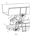
Fig. 7 is a detail elevation view of a second embodiment of the invention using rocker arm and torsion bushings. -
Fig. 8 is a detail perspective view of the rocker arm and torsion bushing assembly shown inFig. 7 . -
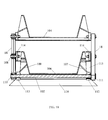
Fig. 9 is a detail elevation view of a third embodiment of the invention in which the torsion bar spring assembly is located below the lower trough. -
Fig. 10 is a cross-section view of the assembly shown inFig. 9 taken along lines 10-10. -
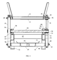
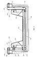
Fig. 11 is an elevation view of a fourth embodiment of the invention having uneven rocker bars to reduce the overall height. -
Fig. 12 is a cross-section view of the assembly shown inFig.11 taken along lines 12-12. -
Fig. 13 is a plan view of a screen for use in the invention. -
Fig. 14 is a cross-section view of the screen shown inFig. 13 taken along lines 14-14. -
Fig. 15 is a cross-section view of the screen shown inFig. 13 taken along lines 15-15. -
Fig. 16 is a plan view of a second embodiment of the vibratory drive. -
Fig. 17 is a side view of the vibratory drive shown inFig. 16 . -
Fig. 18 is a rear view of the vibratory drive shown inFig. 16 . -
Fig. 19 is a perspective view of the vibratory drive shown inFig. 16 . - Throughout the following description specific details are set forth in order to provide a more thorough understanding to persons skilled in the art. However, well known elements may not have been shown or described in detail to avoid unnecessarily obscuring the disclosure. Accordingly, the description and drawings are to be regarded in an illustrative, rather than a restrictive, sense.
- With reference to
Fig. 1 , avibratory conveyor 10 having a flow direction as shown has a conveyingtrough 12, connected tobase 14 and pivotingcounterweight 16 byrocker arms 18 arranged in pairs on each side oftrough 12.Motor 20drives drive wheel 22 throughdrive belt 24. As shown inFig. 3 in whichdrive wheel 22 is removed for illustration,drive wheel 22 has aneccentric axle 26 which transmits a vibratory motion to trough 12 through connectingarm 28 and coilspring 30 which is connected totrough 12 throughflange 31. Other forms of a flexible connection could be used instead ofcoil spring 30, such as a rubber connector.Base 14 is raised off a supportingsurface 33 by a number oflegs 32. Alower trough 34 connected tocounterweight 16 may also be used as an additional counterweight while forming a lower conveyor used to convey materials.Trough 12 has aninner surface 13 which may be perforated, as further described below in reference toFig. 13-15 , to screen particles which fall through totrough 34 to act as a lower conveyor to convey the screened material. - As shown in
Figures 4 ,5 and6 , eachrocker arm 18 is pivotally connected at its upper end totrough 12 onaxle 36 which is journaled inrocker arm 18 in bushing 38.Axle 36 is fixed totrough 12 bybolt 40. Rockerarm 18 is pivotally connected at its lower end onaxle 42 which is journaled inrocker arm 18 in bushing 44.Axle 42 is fixed tocounterweight 16 bybolt 45.Weights 46 may be placed incounterweight pan 47 to match or fine tune the weight of thecounterweight 16 to that of thetrough 12. The center ofrocker arm 18 is provided with acircular opening 52 for receiving the end oftorsion bar 50. The end oftorsion bar 50 is secured fixedly inaperture 52 by a keyless shaft-hub friction connector 54 such as a B-LOC™ keyless shaft- hub friction connector. The other end oftorsion bar 50 is secured fixedly inaperture 56 offlange 58 also by a keyless shaft/hub friction connector 60 or by other suitable means.Flange 58 is secured to base 14 by bolts, welding or the like.Horizontal torsion bar 50 pivots inbushing 64 mounted inaperture 66 offlange 68 which is secured to base 14 by bolts, welding or the like.Transverse members 62 join the parallellongitudinal members 70 ofbase 14.Fig. 6 illustrates a preferred configuration in which a pair oftorsion bars 50, 50' is mounted in each set offlanges rocker arm 18, slightly offset to permit installation. - Horizontal torsion bars 50 may be made of any suitable fatigue-resistant material and will vary depending on the application. A preferred form of torsion bars comprises spring steel cylindrical bars, and more preferably precision ground rounds such as C1045 or 4140HTSR, high carbon 5160H heat treated bars.
Bars 50 should be free of any nicks or marks. Other suitable cylindrical bars of metal or other material may be used. In the embodiment shown inFig. 1-6 ,horizontal torsion bars 50 are mounted half-way between the points of rotation ofaxles counterweight 16 to that of the loadedtrough 12 this results in balancing of the vibratory forces transmitted through the base 14 to the supporting structure. The angle of attack A (Fig. 5 ) is the angle of therocker arms 18 from vertical. It can be varied to vary the speed of conveying by rotating the rocker arms around their node or stationary pivot point (which inFig. 5 is the central axis of torsion bars 50) thereby changing their inclination. Suitable angles of attack have been found to be 30 degrees plus or minus 15 degrees. The direction of transport can be changed by rotating the rocker arms to the other side of a vertical line through their node or stationary pivot point. Angle B inFig. 5 is the total angle through which the end oftorsion bar 50 which is fixed inrocker arm 18 twists. A typical setup will see a displacement or twist of the end oftorsion bar 50 of a few degrees from the rest position, for a total twist in a cycle of twice that angle. The stroke of the conveyor, namely the horizontal displacement of the trough with each vibration at the steady state forced vibration frequency oftorsion bars 50, is a function of the length of the rocker arm, the weight of thetrough 12 andcounterweight 16, the frequency of the vibration, the number and length and diameter of the torsion bars 50 and the modulus of elasticity of the torsion bars 50. In the configuration described, the rocker arms also provide a vertical component of vibratory movement which in combination with the horizontal component causes the particulate material to be conveyed when in operation. - For different size conveyors having differing widths,
torsion bars 50 having different diameters will be advisable, since the spring force of thebars 50 is a function of the diameter and length of the bars. Torsion bars having a variable or progressive spring rate can also be provided by varying the diameter of the torsion bar along the length of the bar. - In operation,
motor 20 is started and oscillatory motion is transmitted throughflange 31 totrough 12. Such oscillatory motion causesrocker arms 18 to start to pivot about the central axes oftorsion bars 50 at increasing angles of displacement until a steady state oscillation is reached at a smooth operational state, referred to herein as the "natural frequency" of torsion bars 50. The stationary pivot point about which the rocker arms pivot at their natural frequency is referred to as their "node". Particulate material placed onsurface 13 oftrough 12 is then conveyed due to the vertical component of vibration accompanying the horizontal component of vibration. If desired, thelower trough 34 can be used as a second vibratory conveyor to transport material from another source or screened from theconveyor trough 12 above. - The conveying speed may be varied by varying the frequency of vibration. This can be accomplished by varying the speed of
motor 20. This can be done simply by use of a variable frequency drive to vary the frequency of the electric power provided to themotor 20. Forexample motor 20 may run at 1800 rpm with a 60 hertz frequency of the electric power provided. Using a variable frequency drive the speed of the motor can be increased or decreased by varying the electrical power above or below 60 hertz by varying the frequency drive. In turn this will vary the conveying speed. The frequency of the drive may alternatively be varied by the use of variable pitch belt sheaves or other variable- RPM arrangement. -
Figures 7 and8 illustrate an alternate embodiment in which torsion bars 50 are replaced withtorsion bushings 80. Thetorsion bushing 80 has an outercylindrical metal surface 88 which is welded to therocker arm 18 and an innercylindrical bushing surface 86 which is secured to flange 84 bybolt 82. The material 81 betweensurfaces cylindrical bushing surface 86 of thetorsion bushing 80 can be welded to therocker arm 18 and the outercylindrical metal surface 88 secured toflange 84. Similar torsion bushings can be provided at any one, or two or all of the pivot axes 83, 85, 87 ofrocker arms 118. -
Figures 9 and10 illustrate an alternate embodiment of theconveyor 100 having two conveyingtroughs torsion bar 102 is located beneath thelower trough 106 in order to clear the space above thelower trough 106. In this case thecentral axis 108 ofrocker arms 18 pivots freely oncentral beam 114 which is fixed onlegs 115 tobase 116. Thelower pivot point 110 ofrocker arms 18 is fixed on one end oftorsion bar 102 in the manner described above while theother end 111 oftorsion bar 102 is fixed inflange 112, which in turn is connected totrough 106 byplate 107.Torsion bar 102 rotates inflange 113 which is secured totrough 106 byplate 109. Otherwise this embodiment functions as in the first embodiment.Motor 20 can be mounted centrally of the conveyor lengthwise withsprings 30 straddling either side oftrough 106.Motor 20 can also be mounted towards either end of the conveyor. Similarly thetorsion bars 102 can be located abovetrough 104 or at any one, or two or all of the pivot axes ofrocker arms 18. -
Figures 11 and12 illustrate an alternate embodiment of theconveyor 120 having a low profile to reduce the overall height of the machine. A single conveyingtrough 122 is provided and thetorsion bar 124 is located beneath the conveying trough. To achieve a lower height the rocker arms have uneven lengths about thecentral pivot point 128. That is, the length C of the arm from thelower axis 126 to thecentral axis 128 is greater than the length D of the arm from theupper axis 130 to thecentral axis 128. The upper end ofrocker arms 118 are pivotally connected to parallellongitudinal balance beams 132 bybolts 138 as described above. Balance beams 132 provide the upper counterweight during the oscillatory motion. They may be stiffened to move in unison by providingconnector bars 134 which are connected bybeams 136 extending beneath the torsion bars 124. Thecenter 128 ofrocker arms 118 is connected to parallelcentral beams 142 bybolts 140 as described above.Beams 142 are secured tolegs 135.Motor 20 can be mounted in the center of the conveyor lengthwise withsprings 30 straddling either side oftrough 122.Motor 20 can also be mounted towards either end of the conveyor. -
Figures 13 to 15 illustrate a design for theconveyor trough 150 with a slotted profiled screenhorizontal support surface 152, in the case of a conveyor moving particles in the direction from right to left inFig. 13 . This is an alternative to theinner surface 13 described above in respect ofFig. 2 which may be perforated to screen particles. A series of parallel transverse slottedapertures 154 is formed bytransverse plates 158. A series of divertingbars 156 are secured toplates 158, the lower leading edge ofbars 156 being welded to the upper surface ofplates 158 and the upper trailing edge ofbars 156 being welded to the lower surface ofplates 158.Bars 156 are angled from the vertical on either side of the longitudinal center line of the trough at progressively greater angles as the distance from the center increases in order to fan out the material to prevent plugging. The larger conveyed pieces continue overplates 158 from right to left while the smaller screened pieces drop down throughapertures 154. The divertingbars 156 therefore tend to spread the screened materials away from the center of the conveyor as it passes throughapertures 154. -
Fig. 16 through 19 illustrate a second embodiment of the vibratory drive which is springless.Motor 20 as inFig. 1 drives sheave 216 throughdrive belt 24.Sheave 216 is mounted on aneccentric shaft 214 which rotates in bearing 223 and transmits a vibratory motion torocker arms 18 throughdrive arms rocker arms 18 are pivotally connected to the conveyor troughs onbushings 210 as previously described. A balancingweight 213 is attached toshaft 214 by ahub 212 and lockassembly 234 in order to assist in balancing the drive system by countering the offset ofeccentric shaft 214. Drivearms shaft 214 for rotation onbearings 222 and pivotally connected at theother end 219 to torsionarms 215. In the configuration shown one of thedrive arms 226 is shorter than the other 227.Torsion arms 215 are locked at their upper end ontorsion bars 50 bylock assembly 235 adjacent theflanges 228 in which the end oftorsion bar 50 is free to rotate inbushing 227. The other end oftorsion bar 50 is locked in the central axis ofrocker arm 18 bylock assembly 236. In this way the drive provides a vibratory motion directly totorsion bars 50 which is communicated to therocker arms 18 and thence to the conveyor. - The vibrating conveyor systems described above can be applied generally to vibratory feeders as well as to vibrating screens whereby the angle of attack of the rocker arms can be selected to reduce the amount of conveying movement.
- The present invention therefore provides a vibratory conveyor comprising a frame, and a source of vibratory force mounted on a suitable location for providing vibratory movement to a conveying surface, the conveying surface being pivotally attached to a counterweight element by a plurality of rocker arms, each rocker arm being mounted on the frame for pivoting motion about the central axis of one end of a torsion spring element to which it is fixed, the second end of the torsion spring element being fixed to the frame. Preferably the rocker arms are arranged in opposed pairs, with a first rocker arm in the pair being mounted on a first side of the frame for pivoting motion about the central axis of one end of a first torsion spring element to which it is fixed, the second end of the torsion spring element being fixed to the opposite side of the frame, and a second rocker arm in the pair being mounted on the opposite side of the frame for pivoting motion about the central axis of one end of a second torsion spring element to which it is fixed, the second end of the torsion spring element being fixed to the first side of the frame. Alternatively other arrangements of torsion spring element configurations can be used.
- The present invention further provides a method of conveying material comprising i) providing a vibratory conveyor comprising a frame, and a source of vibratory force mounted on the frame for providing vibratory movement to a conveying surface, the conveying surface being pivotally attached to a counterweight element by a plurality of rocker arms, each rocker arm being mounted on the frame for pivoting motion about the central axis of one end of a torsion spring element to which it is fixed, the second end of the torsion spring element being fixed to the frame; ii) applying vibratory movement to the conveying surface and thereby applying corresponding vibratory movement to the counterweight element until a steady state oscillation is reached at or near a natural frequency of the torsion elements; and iii) either before or after step ii) transferring the material to or placing the material on the conveying surface. Material can also be conveyed on the counterweight element where the counterweight element also provides a conveying surface.
- While a number of exemplary aspects and embodiments have been discussed above, those of skill in the art will recognize certain modifications, permutations, additions and sub-combinations thereof. It is therefore intended that the invention be interpreted to include all such modifications, permutations, additions and sub-combinations as are within their true spirit and scope.
- While a number of exemplary aspects and embodiments have been discussed above, those of skill in the art will recognize certain modifications, permutations, additions and sub-combinations thereof. It is therefore intended that the following appended claims and claims hereafter introduced are interpreted to include all such modifications, permutations, additions and sub-combinations as are within their true spirit and scope.
- The invention is further described by the following embodiments, wherein:
-
Embodiment 1. A vibratory conveyor comprising:- (a) a frame;
- (b) a first conveying member mounted on said frame and having a conveying surface;
- (c) a source of vibratory force for providing vibratory movement to said conveying member;
- Embodiment 2: The vibrating conveyor with the features of
embodiment 1 wherein each said connecting arm is biased for oscillating motion about said third axis of rotation by being mounted on said frame for oscillating motion about the central axis of one end of a torsion spring element to which it is fixed, the second end of said torsion spring element being fixed to the frame. - Embodiment 3: The vibrating conveyor with the features of embodiment 2 wherein said torsion spring element is a torsion bar.
- Embodiment 4: The vibrating conveyor with the features of embodiment 2 wherein said torsion spring element is a cylindrical torsion bushing, the outer surface of which is the first end of said torsion spring element and the inner surface of which is the second end of said torsion spring element.
- Embodiment 5: The vibrating conveyor with the features of embodiment 2 wherein said torsion spring element is a cylindrical torsion bushing, the inner surface of which is the first end of said torsion spring element and the outer surface of which is the second end of said torsion spring element.
- Embodiment 6: The vibrating conveyor with the features of embodiment 2 wherein said connecting arms are arranged in opposed pairs, with a first rocker arm in the pair being mounted on a first side of the frame for pivoting motion about the central axis of one end of a first torsion bar, the second end of the torsion bar being fixed to the opposite side of the frame, and a second rocker arm in the pair being mounted on the opposite side of the frame for oscillating motion about the central axis of one end of a second torsion bar, the second end of the torsion bar being fixed to the first side of the frame.
- Embodiment 7: The vibrating conveyor with the features of
embodiment 1 wherein said counterweighting member comprises a second conveying surface for the transport of particulate material. - Embodiment 8: The vibrating conveyor with the features of embodiment 2 wherein said central axis of one end of a torsion spring element is provided at any one or more of said first, second or third axes of rotation of said connecting arms.
- Embodiment 9: The vibrating conveyor with the features of
embodiment 1 wherein an adjustable material transport speed is provided by varying the frequency of said source of vibratory force. - Embodiment 10: The vibrating conveyor with the features of embodiment 9 wherein said frequency of said source of vibratory force is varied by the use of a variable frequency drive.
- Embodiment 11: The vibrating conveyor with the features of embodiment 9 wherein said frequency of said source of vibratory force is varied by the use of variable pitch belt sheaves.
- Embodiment 12: The vibrating conveyor with the features of
embodiment 1 wherein the conveying speed and direction can be adjusted by adjusting the angle of attack of said connecting arms by rotating said arms about said third axis of rotation thereby changing their inclination to the vertical. - Embodiment 13: The vibrating conveyor with the features of
embodiment 12 wherein said angle of attack is set between 15 degrees and 45 degrees from either side of vertical. - Embodiment 14: The vibrating conveyor with the features of
embodiment 1 wherein said source of vibratory force comprises an eccentric shaft comprising eccentric cams offset by 180°. - Embodiment 15: A method of conveying material comprising: a) providing a vibratory conveyor comprising a frame, and a source of vibratory force for providing vibratory movement to a conveying member comprising a conveying surface, the conveying member being pivotally connected to a counterweighting member by a plurality of connecting arms, each connecting arm being pivotally connected at one end thereof to said first conveying member at a first axis of rotation, to said counterweighting member at a second axis of rotation and being biased for oscillating motion about a third axis of rotation; b) applying vibratory movement to the conveying surface and thereby applying corresponding vibratory movement to the counterweight member until a steady state oscillation about said third axis of rotation is reached; and iii) either before or after step ii) transferring the material to or placing the material on the conveying surface.
- Embodiment 16: A vibrating conveyor, comprising:
- a) a frame;
- b) a first conveying member mounted on said frame and having a conveying surface, said first conveying member forming a first mass;
- c) a source of vibratory force for providing vibratory movement to said conveying member,
- d) a second mass, joined by a plurality of connecting arms to said first mass, whereby said two masses oscillate in opposite directions, and wherein said connecting arms are connected to torsion bar spring elements to produce a balanced vibrating system.
- Embodiment 17: The vibrating conveyor with the features of
embodiment 16 wherein either one of said two masses may consist of a plurality of submasses which plurality of submasses vibrates as a single mass. - Embodiment 18: The vibrating conveyor with the features of
embodiment 16 wherein said masses oscillate about a stationary node point located on each said connecting arm thereby providing synchronized movement in opposite directions of the two oscillating masses. - Embodiment 19: The vibrating conveyor with the features of
embodiment 18 wherein the location of the node point on each said connecting arm is selected such that the forces generated by the two opposing oscillating masses cancel out each other to provide a balanced vibrating system. - Embodiment 20: The vibrating conveyor with the features of embodiment 19 wherein said second mass comprises a conveying surface for the transport of material.
- Embodiment 21: The vibrating conveyor with the features of embodiment 19 wherein the magnitude of said two masses is selected so that in operation said masses oscillate at or near the natural frequency of the balanced vibrating system.
- Embodiment 22: The vibrating conveyor with the features of
embodiment 16 wherein said torsion bar spring elements are attached to said connecting arms at the node point of said connecting arms. - Embodiment 23: The vibrating conveyor with the features of
embodiment 16 wherein said second mass is joined by a plurality of connecting arms to said first mass at first and second axes of rotation, and said torsion bar spring elements are attached to said connecting arms at one or more of said first and second axes of rotation and said node points. - Embodiment 24: The vibrating conveyor with the features of
embodiment 16 wherein an adjustable material transport speed is provided by varying the frequency of said source of vibratory force. - Embodiment 25: The vibrating conveyor with the features of embodiment 23 wherein said frequency of said source of vibratory force is varied by the use of a variable frequency drive.
- Embodiment 26: The vibrating conveyor with the features of embodiment 23 wherein said frequency of the source of vibratory force is varied by the use of variable pitch belt sheaves.
- Embodiment 27: The vibrating conveyor with the features of
embodiment 16 wherein the conveying speed and direction can be adjusted by adjusting the angle of attack of said connecting arms by rotating said arms about their axis of rotation thereby changing their inclination to the vertical. - Embodiment 28: The vibrating conveyor with the features of
embodiment 26 wherein said angle of attack is set between 15 degrees and 45 degrees from either side of vertical. - Embodiment 29: The vibrating conveyor with the features of
embodiment 16 wherein said second mass oscillates 180° out of phase with said first mass. - Embodiment 30: The vibrating conveyor with the features of
embodiment 16 wherein said source of vibratory force comprises an eccentric shaft with the eccentric cams offset by 180°.
Claims (14)
- A vibratory conveyor (10) comprising:(a) a frame (14);(b) a first conveying member (12) mounted on said frame (14) and having a con-veying surface;(c) a source of vibratory force (20) for providing vibratory movement to said con-veying member;wherein said first conveying member (12) is pivotally connected to a counter-weighting member (16) by a plurality of connecting arms (18), each connecting arm (18) being pivotally connected to said first conveying member (12) at a first axis of rotation, to said counterweighting member (16) at a second axis of rotation and being biased for oscillating motion about a third axis of rotation,
wherein each said connecting arm (18) is biased for oscillating motion about said third axis of rotation by being mounted on said frame (14) for oscillating motion about the central axis a first end of a torsion bar (50) to which it is fixed,
characterized in that the second end of each said torsion bar (50) is fixed to the frame (14); and wherein said source of vibratory force comprises two drive arms each driven at one end thereof by an eccentric rotatable shaft and each pivotally connected at the other end thereof to one end of a connecting arm, the other end of each said connecting arm being fixed to one of said torsion bars adjacent the first end of said torsion bar. - The vibrating conveyor of claim 1 wherein said connecting arms (18) are arranged in opposed pairs, with a first connecting arm (18) in the pair being mounted on a first side of the frame (14) for pivoting motion about the central axis of one end of a first torsion bar (50), the second end of the torsion bar (50) being fixed to the opposite side of the frame (14), and a second connecting arm (18') in the pair being mounted on the opposite side of the frame (14) for oscillating motion about the central axis of one end of a second torsion bar (50'), the second end of the torsion bar (50') being fixed to the first side of the frame (14).
- The vibrating conveyor of claim 1 wherein said counterweighting member (16) comprises a second conveying surface for the transport of particulate material.
- The vibrating conveyor of claim 1 wherein said torsion bar (50) is provided at any one or more of said first, second or third axes of rotation of said connecting arms (18).
- The vibrating conveyor of claim 1 wherein an adjustable material transport speed is provided by varying the frequency of said source of vibratory force (20).
- The vibrating conveyor of claim 1 wherein the conveying speed and direction of said vibrating conveyor (10) is adjusted by adjusting the angle of attack A of said con-necting arms (18) by rotating said arms (18) about said third axis of rotation thereby changing their inclination to the vertical.
- The vibrating conveyor of claim 6 wherein said angle of attack A is set between 15 degrees and 45 degrees from either side of vertical.
- A vibrating conveyor of claim 1 wherein said first conveying member (12) forms a first mass, and said counterweighting member (16) forms a second mass, joined by a plurality of connecting arms (18) to said first mass, whereby said first and second masses oscillate in opposite directions, and wherein said first and second masses oscillate about a stationary node point located on each said connecting arm (18) thereby providing synchronized movement in opposite directions of the oscillating first and second masses, and wherein said connecting arms (18) are connected to each said torsion bars (50) at the node point of said connecting arms (18) to produce a balanced vibrating system.
- The vibrating conveyor of claim 8 wherein either one of said first and second masses may consist of a plurality of submasses which plurality of said submasses vibrates as a single mass.
- The vibrating conveyor of claim 9 wherein the location of the node point on each said connecting arm is selected such that the forces generated by the two opposing oscillating masses cancel out each other to provide a balanced vibrating system.
- The vibrating conveyor of claim 8 wherein the magnitude of said two masses is selected so that in operation said masses oscillate at or near the natural frequency of the balanced vibrating system.
- The vibrating conveyor of claim 8 wherein said second mass is joined by a plurality of connecting arms (18) to said first mass at first and second axes of rotation, and said torsion bars (50) are attached to said connecting arms (18) at one or more of said first and second axes of rotation and said node points to produce a balanced vibrating system.
- The vibrating conveyor of claim 1 wherein said drive arms differ in length.
- A method of conveying material using the vibratory conveyor of claim 1, comprisingi) applying vibratory movement to the conveying surface until a steady state oscillation about said third axis of rotation is reached;ii) varying the velocity of conveyance of the material by varying the frequency of said source of vibratory force andiii) either before or after step ii) transferring the material to or placing the material onto the conveying surface.
Applications Claiming Priority (3)
| Application Number | Priority Date | Filing Date | Title |
|---|---|---|---|
| US7539708P | 2008-06-25 | 2008-06-25 | |
| PCT/CA2009/000899 WO2009155710A1 (en) | 2008-06-25 | 2009-06-25 | Vibratory conveyor |
| EP09768680.2A EP2303730B1 (en) | 2008-06-25 | 2009-06-25 | Vibratory conveyor |
Related Parent Applications (2)
| Application Number | Title | Priority Date | Filing Date |
|---|---|---|---|
| EP09768680.2A Division-Into EP2303730B1 (en) | 2008-06-25 | 2009-06-25 | Vibratory conveyor |
| EP09768680.2A Division EP2303730B1 (en) | 2008-06-25 | 2009-06-25 | Vibratory conveyor |
Publications (2)
| Publication Number | Publication Date |
|---|---|
| EP2998245A1 true EP2998245A1 (en) | 2016-03-23 |
| EP2998245B1 EP2998245B1 (en) | 2022-11-09 |
Family
ID=41443953
Family Applications (2)
| Application Number | Title | Priority Date | Filing Date |
|---|---|---|---|
| EP15157055.3A Active EP2998245B1 (en) | 2008-06-25 | 2009-06-25 | Vibratory conveyor |
| EP09768680.2A Not-in-force EP2303730B1 (en) | 2008-06-25 | 2009-06-25 | Vibratory conveyor |
Family Applications After (1)
| Application Number | Title | Priority Date | Filing Date |
|---|---|---|---|
| EP09768680.2A Not-in-force EP2303730B1 (en) | 2008-06-25 | 2009-06-25 | Vibratory conveyor |
Country Status (5)
| Country | Link |
|---|---|
| US (1) | US8464861B2 (en) |
| EP (2) | EP2998245B1 (en) |
| AU (1) | AU2009261920B2 (en) |
| CA (1) | CA2726464C (en) |
| WO (1) | WO2009155710A1 (en) |
Cited By (2)
| Publication number | Priority date | Publication date | Assignee | Title |
|---|---|---|---|---|
| CN105438736A (en) * | 2015-12-25 | 2016-03-30 | 黄丽 | Swinging device |
| PL449891A1 (en) * | 2024-09-25 | 2026-03-30 | Akademia Górniczo-Hutnicza im. Stanisława Staszica w Krakowie | Vibrating conveyor |
Families Citing this family (22)
| Publication number | Priority date | Publication date | Assignee | Title |
|---|---|---|---|---|
| US8915375B2 (en) * | 2010-11-08 | 2014-12-23 | Terex Usa, Llc | Vibrating screen suspension systems |
| DE102011089050A1 (en) | 2011-12-19 | 2013-06-20 | Vibra Maschinenfabrik Schultheis Gmbh & Co. | Vibration conveyor for feeding free flowing bulk materials, has vibration exciter coupled to base frame, such that vibrations are induced in base frame parallel to conveyor direction, where base frame is connected to conveyor duct |
| US9776805B2 (en) | 2013-05-13 | 2017-10-03 | Key Technology, Inc. | Linear motion conveyor |
| US9668417B2 (en) * | 2014-01-28 | 2017-06-06 | Oxbo International Corporation | Agitated harvester conveyor |
| US10016328B1 (en) | 2014-04-23 | 2018-07-10 | Global Manufacturing Inc. | Platform vibration generator |
| US9408283B2 (en) * | 2014-06-23 | 2016-08-02 | Key Technology, Inc. | Electrical grounding arm |
| ITPO20140011U1 (en) * | 2014-09-09 | 2016-03-09 | Biancalani Srl | VIBRATOR SYSTEM FOR FABRIC TREATMENT |
| CN104444134A (en) * | 2014-11-10 | 2015-03-25 | 南通联振重工机械有限公司 | Double-tank-conveying balanced type vibrating conveyor |
| CN104549980B (en) * | 2015-01-12 | 2017-02-01 | 黑龙江恒益电气股份有限公司 | Reciprocating oscillation conveyor |
| EP3075683A1 (en) | 2015-04-02 | 2016-10-05 | Bühler AG | Conveyor, stopping arrangement for a conveyor, method for conveying and/or singularizing bulk items, kit and method for retrofitting conveyors |
| WO2017023469A1 (en) * | 2015-08-04 | 2017-02-09 | Key Technology, Inc. | Improved linear motion conveyor |
| CN105438737A (en) * | 2015-12-25 | 2016-03-30 | 黄丽 | Automated production vibrating conveyer driving system |
| CN105417031A (en) * | 2015-12-27 | 2016-03-23 | 黄丽 | Conveying assembly |
| CN105366292A (en) * | 2015-12-27 | 2016-03-02 | 黄丽 | Vibrating conveyor |
| DE102016115800A1 (en) * | 2016-08-25 | 2018-03-01 | Hauni Maschinenbau Gmbh | Rotary joint cartridge for a vibrating conveyor gutter handle of a vibrating conveyor trough of the tobacco processing industry |
| KR101966760B1 (en) * | 2016-12-28 | 2019-04-08 | (주)에이피텍 | Apparatus for transferring a mask used for a lens module of a camera |
| EP3585710A1 (en) * | 2017-02-21 | 2020-01-01 | Cabinplant International A/S | A vibration separator system for conveying and separating meat pieces |
| US10946415B2 (en) * | 2018-04-30 | 2021-03-16 | Vermeer Manufacturing Company | Shaker assemblies having a vibratory screen clamping system |
| KR20220159946A (en) | 2020-03-30 | 2022-12-05 | 신포니아 테크놀로지 가부시끼가이샤 | Vibratory transport device and multi-row vibratory transport system having the same |
| US11358801B2 (en) * | 2020-06-12 | 2022-06-14 | Paul Blake Svejkovsky | Differential impulse conveyor |
| CN112357474A (en) * | 2020-11-30 | 2021-02-12 | 贵阳黔江宏宇机械设备有限公司 | Connecting device for oscillating conveyor rocker arm and preventing rocker arm from falling off |
| US11939167B2 (en) * | 2021-05-17 | 2024-03-26 | General Kinematics Corporation | Vibratory apparatus with electro-mechanical sensor |
Citations (5)
| Publication number | Priority date | Publication date | Assignee | Title |
|---|---|---|---|---|
| GB759021A (en) * | 1953-04-22 | 1956-10-10 | Heinz Sernetz | Improvements relating to vibratory machines |
| FR1146129A (en) * | 1955-02-08 | 1957-11-06 | Oscillating machine comprising oscillating members grouped in pairs to form an oscillating mechanism with two masses | |
| US2936064A (en) * | 1957-12-27 | 1960-05-10 | Dravo Corp | Vibratory bulk material conveyor mechanism |
| GB1122478A (en) * | 1966-05-18 | 1968-08-07 | Binder Co Ag | Oscillating working machine with a pair of masses oscillating in opposite directions and connected by links |
| JP2000142949A (en) * | 1998-11-04 | 2000-05-23 | Shinko Electric Co Ltd | Linker type vibrating conveyor |
Family Cites Families (20)
| Publication number | Priority date | Publication date | Assignee | Title |
|---|---|---|---|---|
| US2821292A (en) * | 1953-12-29 | 1958-01-28 | Syntron Co | Torsion bar mounted vibratory motors |
| US3362524A (en) * | 1966-06-15 | 1968-01-09 | State Steel Products Inc | Material handling vibrating apparatus |
| GB1256225A (en) * | 1968-03-19 | 1971-12-08 | Driver Southall | Improvements in vibratory feeders |
| US3625346A (en) * | 1969-06-25 | 1971-12-07 | State Steel Products Inc | Stabilizing means for a vibratory conveyor apparatus |
| US3655032A (en) * | 1970-05-26 | 1972-04-11 | Russell Co Inc Arthur | Vibratory feeder |
| US3932442A (en) * | 1973-08-27 | 1976-01-13 | Lundy Electronics & Systems, Inc. | Process for screening materials with vibrating screens |
| US3865231A (en) * | 1974-01-28 | 1975-02-11 | Fmc Corp | Roller band mechanism and suspension system for oscillating conveyors |
| US5094342A (en) * | 1979-07-02 | 1992-03-10 | General Kinematics Corporation | Vibratory conveyor |
| CA1139253A (en) * | 1979-07-02 | 1983-01-11 | Richard B. Kraus | Vibratory apparatus |
| DE3305998A1 (en) | 1983-02-22 | 1984-08-23 | Robert Bosch Gmbh, 7000 Stuttgart | VIBRATING CONVEYOR WITH RIBBING CONVEYOR |
| US5794757A (en) * | 1996-03-15 | 1998-08-18 | Paul A. Svejkovsky | Differential impulse conveyor and method |
| US5746322A (en) * | 1996-07-02 | 1998-05-05 | Action Equipment Co., Inc. | Vibratory finger screen with lateral wedge members |
| US5938001A (en) * | 1997-01-16 | 1999-08-17 | Fmc Corporation | Vibratory conveyor apparatus with phase-optimized conveyor drive |
| US6415913B2 (en) * | 1997-03-17 | 2002-07-09 | Fmc Technologies, Inc. | Excited base conveyor system |
| US6112883A (en) * | 1998-08-04 | 2000-09-05 | General Kinematics Corporation | Vibratory distribution conveyor |
| DE10016979C1 (en) * | 2000-04-06 | 2001-08-30 | Joest Gmbh & Co Kg | Sieve device, for sifting damp or sticking material, includes vibrating frame coupled to carrier frame using torsion-rod springs |
| AT411577B (en) * | 2002-09-19 | 2004-03-25 | Hmh Engineering Consulting Tra | DEVICE FOR SEPARATING COARSE GRAIN AND FINE GRAIN |
| RU2254173C2 (en) | 2003-06-02 | 2005-06-20 | Тольяттинский государственный университет | Torsional vibration generator |
| JP4635120B2 (en) * | 2005-03-16 | 2011-02-16 | 太洋マシナリー株式会社 | Vibration reduction device for vibrating conveyor |
| US7534358B2 (en) * | 2006-03-20 | 2009-05-19 | Elgin National Industries, Inc. | Horizontal vibratory centrifuge apparatus |
-
2009
- 2009-06-25 CA CA2726464A patent/CA2726464C/en active Active
- 2009-06-25 EP EP15157055.3A patent/EP2998245B1/en active Active
- 2009-06-25 WO PCT/CA2009/000899 patent/WO2009155710A1/en not_active Ceased
- 2009-06-25 AU AU2009261920A patent/AU2009261920B2/en not_active Ceased
- 2009-06-25 US US12/995,397 patent/US8464861B2/en active Active
- 2009-06-25 EP EP09768680.2A patent/EP2303730B1/en not_active Not-in-force
Patent Citations (5)
| Publication number | Priority date | Publication date | Assignee | Title |
|---|---|---|---|---|
| GB759021A (en) * | 1953-04-22 | 1956-10-10 | Heinz Sernetz | Improvements relating to vibratory machines |
| FR1146129A (en) * | 1955-02-08 | 1957-11-06 | Oscillating machine comprising oscillating members grouped in pairs to form an oscillating mechanism with two masses | |
| US2936064A (en) * | 1957-12-27 | 1960-05-10 | Dravo Corp | Vibratory bulk material conveyor mechanism |
| GB1122478A (en) * | 1966-05-18 | 1968-08-07 | Binder Co Ag | Oscillating working machine with a pair of masses oscillating in opposite directions and connected by links |
| JP2000142949A (en) * | 1998-11-04 | 2000-05-23 | Shinko Electric Co Ltd | Linker type vibrating conveyor |
Cited By (3)
| Publication number | Priority date | Publication date | Assignee | Title |
|---|---|---|---|---|
| CN105438736A (en) * | 2015-12-25 | 2016-03-30 | 黄丽 | Swinging device |
| PL449891A1 (en) * | 2024-09-25 | 2026-03-30 | Akademia Górniczo-Hutnicza im. Stanisława Staszica w Krakowie | Vibrating conveyor |
| EP4717635A1 (en) | 2024-09-25 | 2026-04-01 | Akademia Gorniczo-Hutnicza im. Stanislawa Staszica w Krakowie | Vibrating conveyor |
Also Published As
| Publication number | Publication date |
|---|---|
| EP2303730B1 (en) | 2015-06-03 |
| US8464861B2 (en) | 2013-06-18 |
| CA2726464C (en) | 2015-03-31 |
| AU2009261920B2 (en) | 2015-03-26 |
| EP2303730A1 (en) | 2011-04-06 |
| AU2009261920A1 (en) | 2009-12-30 |
| WO2009155710A1 (en) | 2009-12-30 |
| US20110083944A1 (en) | 2011-04-14 |
| EP2303730A4 (en) | 2012-06-27 |
| EP2998245B1 (en) | 2022-11-09 |
| CA2726464A1 (en) | 2009-12-30 |
Similar Documents
| Publication | Publication Date | Title |
|---|---|---|
| EP2998245B1 (en) | Vibratory conveyor | |
| JP3842355B2 (en) | 2-way vibratory feeder or vibratory conveyor | |
| EP2910313B1 (en) | Screen assembly | |
| US6349834B1 (en) | Vibratory screen separator | |
| EP2907589B1 (en) | Material screening apparatus with multi-mode screen box | |
| EP0128193A4 (en) | Center flow feeder and vibratory conveyor. | |
| US6298978B1 (en) | Reversing natural frequency vibratory conveyor system | |
| JP3093193B2 (en) | Vibration conveyor with driver on the side | |
| AU770303B2 (en) | Motor base for vibratory apparatus | |
| AU2015203589B2 (en) | Vibratory conveyor | |
| US2725984A (en) | Vibratory conveyors | |
| US5109633A (en) | Workpeice tumbling and conveying apparatus | |
| EP3842158A1 (en) | Vibrating screen, especially with slotted sieve, and method for controlling the operation of the screen, especially with slotted sieve | |
| EP2603328B1 (en) | Screening apparatus | |
| JPH05319537A (en) | Vibrating conveyor | |
| US3346097A (en) | Adjustable stroke vibratory feeder | |
| US3217864A (en) | Circular vibrating conveyors | |
| US1999768A (en) | Screening device | |
| JPS5915850B2 (en) | vibrating conveyor | |
| CN119947836A (en) | Electric vibrating machines for mineral material processing equipment | |
| PL214240B1 (en) | Reversible vibratory conveyor | |
| WO1993022102A1 (en) | Workpiece tumbling and conveying apparatus | |
| DE10217602A1 (en) | Drive for a vibrating trough | |
| JPS5832124B2 (en) | Vibrating parts conveyor | |
| UA61166C2 (en) | Vibrating stirrer |
Legal Events
| Date | Code | Title | Description |
|---|---|---|---|
| PUAI | Public reference made under article 153(3) epc to a published international application that has entered the european phase |
Free format text: ORIGINAL CODE: 0009012 |
|
| AC | Divisional application: reference to earlier application |
Ref document number: 2303730 Country of ref document: EP Kind code of ref document: P |
|
| AK | Designated contracting states |
Kind code of ref document: A1 Designated state(s): AT BE BG CH CY CZ DE DK EE ES FI FR GB GR HR HU IE IS IT LI LT LU LV MC MK MT NL NO PL PT RO SE SI SK TR |
|
| 17P | Request for examination filed |
Effective date: 20160923 |
|
| RBV | Designated contracting states (corrected) |
Designated state(s): AT BE BG CH CY CZ DE DK EE ES FI FR GB GR HR HU IE IS IT LI LT LU LV MC MK MT NL NO PL PT RO SE SI SK TR |
|
| STAA | Information on the status of an ep patent application or granted ep patent |
Free format text: STATUS: EXAMINATION IS IN PROGRESS |
|
| 17Q | First examination report despatched |
Effective date: 20180626 |
|
| GRAP | Despatch of communication of intention to grant a patent |
Free format text: ORIGINAL CODE: EPIDOSNIGR1 |
|
| STAA | Information on the status of an ep patent application or granted ep patent |
Free format text: STATUS: GRANT OF PATENT IS INTENDED |
|
| INTG | Intention to grant announced |
Effective date: 20220524 |
|
| GRAS | Grant fee paid |
Free format text: ORIGINAL CODE: EPIDOSNIGR3 |
|
| GRAA | (expected) grant |
Free format text: ORIGINAL CODE: 0009210 |
|
| STAA | Information on the status of an ep patent application or granted ep patent |
Free format text: STATUS: THE PATENT HAS BEEN GRANTED |
|
| RAP1 | Party data changed (applicant data changed or rights of an application transferred) |
Owner name: BRUNETTE MACHINERY COMPANY INC. |
|
| AC | Divisional application: reference to earlier application |
Ref document number: 2303730 Country of ref document: EP Kind code of ref document: P |
|
| AK | Designated contracting states |
Kind code of ref document: B1 Designated state(s): AT BE BG CH CY CZ DE DK EE ES FI FR GB GR HR HU IE IS IT LI LT LU LV MC MK MT NL NO PL PT RO SE SI SK TR |
|
| REG | Reference to a national code |
Ref country code: GB Ref legal event code: FG4D |
|
| REG | Reference to a national code |
Ref country code: CH Ref legal event code: EP Ref country code: AT Ref legal event code: REF Ref document number: 1530224 Country of ref document: AT Kind code of ref document: T Effective date: 20221115 |
|
| REG | Reference to a national code |
Ref country code: DE Ref legal event code: R096 Ref document number: 602009064678 Country of ref document: DE |
|
| REG | Reference to a national code |
Ref country code: IE Ref legal event code: FG4D |
|
| REG | Reference to a national code |
Ref country code: LT Ref legal event code: MG9D |
|
| REG | Reference to a national code |
Ref country code: NL Ref legal event code: MP Effective date: 20221109 |
|
| REG | Reference to a national code |
Ref country code: AT Ref legal event code: MK05 Ref document number: 1530224 Country of ref document: AT Kind code of ref document: T Effective date: 20221109 |
|
| PG25 | Lapsed in a contracting state [announced via postgrant information from national office to epo] |
Ref country code: SE Free format text: LAPSE BECAUSE OF FAILURE TO SUBMIT A TRANSLATION OF THE DESCRIPTION OR TO PAY THE FEE WITHIN THE PRESCRIBED TIME-LIMIT Effective date: 20221109 Ref country code: PT Free format text: LAPSE BECAUSE OF FAILURE TO SUBMIT A TRANSLATION OF THE DESCRIPTION OR TO PAY THE FEE WITHIN THE PRESCRIBED TIME-LIMIT Effective date: 20230309 Ref country code: NO Free format text: LAPSE BECAUSE OF FAILURE TO SUBMIT A TRANSLATION OF THE DESCRIPTION OR TO PAY THE FEE WITHIN THE PRESCRIBED TIME-LIMIT Effective date: 20230209 Ref country code: LT Free format text: LAPSE BECAUSE OF FAILURE TO SUBMIT A TRANSLATION OF THE DESCRIPTION OR TO PAY THE FEE WITHIN THE PRESCRIBED TIME-LIMIT Effective date: 20221109 Ref country code: FI Free format text: LAPSE BECAUSE OF FAILURE TO SUBMIT A TRANSLATION OF THE DESCRIPTION OR TO PAY THE FEE WITHIN THE PRESCRIBED TIME-LIMIT Effective date: 20221109 Ref country code: ES Free format text: LAPSE BECAUSE OF FAILURE TO SUBMIT A TRANSLATION OF THE DESCRIPTION OR TO PAY THE FEE WITHIN THE PRESCRIBED TIME-LIMIT Effective date: 20221109 Ref country code: AT Free format text: LAPSE BECAUSE OF FAILURE TO SUBMIT A TRANSLATION OF THE DESCRIPTION OR TO PAY THE FEE WITHIN THE PRESCRIBED TIME-LIMIT Effective date: 20221109 |
|
| PG25 | Lapsed in a contracting state [announced via postgrant information from national office to epo] |
Ref country code: PL Free format text: LAPSE BECAUSE OF FAILURE TO SUBMIT A TRANSLATION OF THE DESCRIPTION OR TO PAY THE FEE WITHIN THE PRESCRIBED TIME-LIMIT Effective date: 20221109 Ref country code: LV Free format text: LAPSE BECAUSE OF FAILURE TO SUBMIT A TRANSLATION OF THE DESCRIPTION OR TO PAY THE FEE WITHIN THE PRESCRIBED TIME-LIMIT Effective date: 20221109 Ref country code: IS Free format text: LAPSE BECAUSE OF FAILURE TO SUBMIT A TRANSLATION OF THE DESCRIPTION OR TO PAY THE FEE WITHIN THE PRESCRIBED TIME-LIMIT Effective date: 20230309 Ref country code: HR Free format text: LAPSE BECAUSE OF FAILURE TO SUBMIT A TRANSLATION OF THE DESCRIPTION OR TO PAY THE FEE WITHIN THE PRESCRIBED TIME-LIMIT Effective date: 20221109 Ref country code: GR Free format text: LAPSE BECAUSE OF FAILURE TO SUBMIT A TRANSLATION OF THE DESCRIPTION OR TO PAY THE FEE WITHIN THE PRESCRIBED TIME-LIMIT Effective date: 20230210 |
|
| PG25 | Lapsed in a contracting state [announced via postgrant information from national office to epo] |
Ref country code: NL Free format text: LAPSE BECAUSE OF FAILURE TO SUBMIT A TRANSLATION OF THE DESCRIPTION OR TO PAY THE FEE WITHIN THE PRESCRIBED TIME-LIMIT Effective date: 20221109 |
|
| PG25 | Lapsed in a contracting state [announced via postgrant information from national office to epo] |
Ref country code: RO Free format text: LAPSE BECAUSE OF FAILURE TO SUBMIT A TRANSLATION OF THE DESCRIPTION OR TO PAY THE FEE WITHIN THE PRESCRIBED TIME-LIMIT Effective date: 20221109 Ref country code: EE Free format text: LAPSE BECAUSE OF FAILURE TO SUBMIT A TRANSLATION OF THE DESCRIPTION OR TO PAY THE FEE WITHIN THE PRESCRIBED TIME-LIMIT Effective date: 20221109 Ref country code: DK Free format text: LAPSE BECAUSE OF FAILURE TO SUBMIT A TRANSLATION OF THE DESCRIPTION OR TO PAY THE FEE WITHIN THE PRESCRIBED TIME-LIMIT Effective date: 20221109 Ref country code: CZ Free format text: LAPSE BECAUSE OF FAILURE TO SUBMIT A TRANSLATION OF THE DESCRIPTION OR TO PAY THE FEE WITHIN THE PRESCRIBED TIME-LIMIT Effective date: 20221109 |
|
| PGFP | Annual fee paid to national office [announced via postgrant information from national office to epo] |
Ref country code: IE Payment date: 20230627 Year of fee payment: 15 Ref country code: DE Payment date: 20230626 Year of fee payment: 15 |
|
| REG | Reference to a national code |
Ref country code: DE Ref legal event code: R097 Ref document number: 602009064678 Country of ref document: DE |
|
| PG25 | Lapsed in a contracting state [announced via postgrant information from national office to epo] |
Ref country code: SK Free format text: LAPSE BECAUSE OF FAILURE TO SUBMIT A TRANSLATION OF THE DESCRIPTION OR TO PAY THE FEE WITHIN THE PRESCRIBED TIME-LIMIT Effective date: 20221109 |
|
| PLBE | No opposition filed within time limit |
Free format text: ORIGINAL CODE: 0009261 |
|
| STAA | Information on the status of an ep patent application or granted ep patent |
Free format text: STATUS: NO OPPOSITION FILED WITHIN TIME LIMIT |
|
| 26N | No opposition filed |
Effective date: 20230810 |
|
| PGFP | Annual fee paid to national office [announced via postgrant information from national office to epo] |
Ref country code: GB Payment date: 20230627 Year of fee payment: 15 |
|
| PG25 | Lapsed in a contracting state [announced via postgrant information from national office to epo] |
Ref country code: SI Free format text: LAPSE BECAUSE OF FAILURE TO SUBMIT A TRANSLATION OF THE DESCRIPTION OR TO PAY THE FEE WITHIN THE PRESCRIBED TIME-LIMIT Effective date: 20221109 |
|
| PG25 | Lapsed in a contracting state [announced via postgrant information from national office to epo] |
Ref country code: MC Free format text: LAPSE BECAUSE OF FAILURE TO SUBMIT A TRANSLATION OF THE DESCRIPTION OR TO PAY THE FEE WITHIN THE PRESCRIBED TIME-LIMIT Effective date: 20221109 |
|
| PG25 | Lapsed in a contracting state [announced via postgrant information from national office to epo] |
Ref country code: MC Free format text: LAPSE BECAUSE OF FAILURE TO SUBMIT A TRANSLATION OF THE DESCRIPTION OR TO PAY THE FEE WITHIN THE PRESCRIBED TIME-LIMIT Effective date: 20221109 |
|
| REG | Reference to a national code |
Ref country code: CH Ref legal event code: PL |
|
| REG | Reference to a national code |
Ref country code: BE Ref legal event code: MM Effective date: 20230630 |
|
| PG25 | Lapsed in a contracting state [announced via postgrant information from national office to epo] |
Ref country code: LU Free format text: LAPSE BECAUSE OF NON-PAYMENT OF DUE FEES Effective date: 20230625 |
|
| PG25 | Lapsed in a contracting state [announced via postgrant information from national office to epo] |
Ref country code: LU Free format text: LAPSE BECAUSE OF NON-PAYMENT OF DUE FEES Effective date: 20230625 |
|
| PG25 | Lapsed in a contracting state [announced via postgrant information from national office to epo] |
Ref country code: CH Free format text: LAPSE BECAUSE OF NON-PAYMENT OF DUE FEES Effective date: 20230630 |
|
| PG25 | Lapsed in a contracting state [announced via postgrant information from national office to epo] |
Ref country code: IT Free format text: LAPSE BECAUSE OF FAILURE TO SUBMIT A TRANSLATION OF THE DESCRIPTION OR TO PAY THE FEE WITHIN THE PRESCRIBED TIME-LIMIT Effective date: 20221109 Ref country code: FR Free format text: LAPSE BECAUSE OF NON-PAYMENT OF DUE FEES Effective date: 20230630 Ref country code: BE Free format text: LAPSE BECAUSE OF NON-PAYMENT OF DUE FEES Effective date: 20230630 |
|
| PG25 | Lapsed in a contracting state [announced via postgrant information from national office to epo] |
Ref country code: BG Free format text: LAPSE BECAUSE OF FAILURE TO SUBMIT A TRANSLATION OF THE DESCRIPTION OR TO PAY THE FEE WITHIN THE PRESCRIBED TIME-LIMIT Effective date: 20221109 |
|
| PG25 | Lapsed in a contracting state [announced via postgrant information from national office to epo] |
Ref country code: BG Free format text: LAPSE BECAUSE OF FAILURE TO SUBMIT A TRANSLATION OF THE DESCRIPTION OR TO PAY THE FEE WITHIN THE PRESCRIBED TIME-LIMIT Effective date: 20221109 |
|
| REG | Reference to a national code |
Ref country code: DE Ref legal event code: R119 Ref document number: 602009064678 Country of ref document: DE |
|
| GBPC | Gb: european patent ceased through non-payment of renewal fee |
Effective date: 20240625 |
|
| PG25 | Lapsed in a contracting state [announced via postgrant information from national office to epo] |
Ref country code: DE Free format text: LAPSE BECAUSE OF NON-PAYMENT OF DUE FEES Effective date: 20250101 |
|
| PG25 | Lapsed in a contracting state [announced via postgrant information from national office to epo] |
Ref country code: IE Free format text: LAPSE BECAUSE OF NON-PAYMENT OF DUE FEES Effective date: 20240625 |
|
| PG25 | Lapsed in a contracting state [announced via postgrant information from national office to epo] |
Ref country code: GB Free format text: LAPSE BECAUSE OF NON-PAYMENT OF DUE FEES Effective date: 20240625 |
|
| PG25 | Lapsed in a contracting state [announced via postgrant information from national office to epo] |
Ref country code: CY Free format text: LAPSE BECAUSE OF FAILURE TO SUBMIT A TRANSLATION OF THE DESCRIPTION OR TO PAY THE FEE WITHIN THE PRESCRIBED TIME-LIMIT; INVALID AB INITIO Effective date: 20090625 |
|
| PG25 | Lapsed in a contracting state [announced via postgrant information from national office to epo] |
Ref country code: HU Free format text: LAPSE BECAUSE OF FAILURE TO SUBMIT A TRANSLATION OF THE DESCRIPTION OR TO PAY THE FEE WITHIN THE PRESCRIBED TIME-LIMIT; INVALID AB INITIO Effective date: 20090625 |
|
| PG25 | Lapsed in a contracting state [announced via postgrant information from national office to epo] |
Ref country code: TR Free format text: LAPSE BECAUSE OF FAILURE TO SUBMIT A TRANSLATION OF THE DESCRIPTION OR TO PAY THE FEE WITHIN THE PRESCRIBED TIME-LIMIT Effective date: 20221109 |