EP2998136A1 - Assembly system for assembling suspension components on a vehicle - Google Patents
Assembly system for assembling suspension components on a vehicle Download PDFInfo
- Publication number
- EP2998136A1 EP2998136A1 EP15388003.4A EP15388003A EP2998136A1 EP 2998136 A1 EP2998136 A1 EP 2998136A1 EP 15388003 A EP15388003 A EP 15388003A EP 2998136 A1 EP2998136 A1 EP 2998136A1
- Authority
- EP
- European Patent Office
- Prior art keywords
- plate
- tank
- assembly system
- underside
- socket
- Prior art date
- Legal status (The legal status is an assumption and is not a legal conclusion. Google has not performed a legal analysis and makes no representation as to the accuracy of the status listed.)
- Withdrawn
Links
Images
Classifications
-
- B—PERFORMING OPERATIONS; TRANSPORTING
- B60—VEHICLES IN GENERAL
- B60G—VEHICLE SUSPENSION ARRANGEMENTS
- B60G11/00—Resilient suspensions characterised by arrangement, location or kind of springs
- B60G11/26—Resilient suspensions characterised by arrangement, location or kind of springs having fluid springs only, e.g. hydropneumatic springs
- B60G11/27—Resilient suspensions characterised by arrangement, location or kind of springs having fluid springs only, e.g. hydropneumatic springs wherein the fluid is a gas
-
- B—PERFORMING OPERATIONS; TRANSPORTING
- B60—VEHICLES IN GENERAL
- B60G—VEHICLE SUSPENSION ARRANGEMENTS
- B60G11/00—Resilient suspensions characterised by arrangement, location or kind of springs
- B60G11/26—Resilient suspensions characterised by arrangement, location or kind of springs having fluid springs only, e.g. hydropneumatic springs
- B60G11/28—Resilient suspensions characterised by arrangement, location or kind of springs having fluid springs only, e.g. hydropneumatic springs characterised by means specially adapted for attaching the spring to axle or sprung part of the vehicle
-
- F—MECHANICAL ENGINEERING; LIGHTING; HEATING; WEAPONS; BLASTING
- F16—ENGINEERING ELEMENTS AND UNITS; GENERAL MEASURES FOR PRODUCING AND MAINTAINING EFFECTIVE FUNCTIONING OF MACHINES OR INSTALLATIONS; THERMAL INSULATION IN GENERAL
- F16F—SPRINGS; SHOCK-ABSORBERS; MEANS FOR DAMPING VIBRATION
- F16F9/00—Springs, vibration-dampers, shock-absorbers, or similarly-constructed movement-dampers using a fluid or the equivalent as damping medium
- F16F9/02—Springs, vibration-dampers, shock-absorbers, or similarly-constructed movement-dampers using a fluid or the equivalent as damping medium using gas only or vacuum
- F16F9/04—Springs, vibration-dampers, shock-absorbers, or similarly-constructed movement-dampers using a fluid or the equivalent as damping medium using gas only or vacuum in a chamber with a flexible wall
- F16F9/0454—Springs, vibration-dampers, shock-absorbers, or similarly-constructed movement-dampers using a fluid or the equivalent as damping medium using gas only or vacuum in a chamber with a flexible wall characterised by the assembling method or by the mounting arrangement, e.g. mounting of the membrane
-
- F—MECHANICAL ENGINEERING; LIGHTING; HEATING; WEAPONS; BLASTING
- F16—ENGINEERING ELEMENTS AND UNITS; GENERAL MEASURES FOR PRODUCING AND MAINTAINING EFFECTIVE FUNCTIONING OF MACHINES OR INSTALLATIONS; THERMAL INSULATION IN GENERAL
- F16F—SPRINGS; SHOCK-ABSORBERS; MEANS FOR DAMPING VIBRATION
- F16F9/00—Springs, vibration-dampers, shock-absorbers, or similarly-constructed movement-dampers using a fluid or the equivalent as damping medium
- F16F9/02—Springs, vibration-dampers, shock-absorbers, or similarly-constructed movement-dampers using a fluid or the equivalent as damping medium using gas only or vacuum
- F16F9/04—Springs, vibration-dampers, shock-absorbers, or similarly-constructed movement-dampers using a fluid or the equivalent as damping medium using gas only or vacuum in a chamber with a flexible wall
- F16F9/05—Springs, vibration-dampers, shock-absorbers, or similarly-constructed movement-dampers using a fluid or the equivalent as damping medium using gas only or vacuum in a chamber with a flexible wall the flexible wall being of the rolling diaphragm type
-
- F—MECHANICAL ENGINEERING; LIGHTING; HEATING; WEAPONS; BLASTING
- F16—ENGINEERING ELEMENTS AND UNITS; GENERAL MEASURES FOR PRODUCING AND MAINTAINING EFFECTIVE FUNCTIONING OF MACHINES OR INSTALLATIONS; THERMAL INSULATION IN GENERAL
- F16F—SPRINGS; SHOCK-ABSORBERS; MEANS FOR DAMPING VIBRATION
- F16F9/00—Springs, vibration-dampers, shock-absorbers, or similarly-constructed movement-dampers using a fluid or the equivalent as damping medium
- F16F9/32—Details
- F16F9/54—Arrangements for attachment
-
- B—PERFORMING OPERATIONS; TRANSPORTING
- B60—VEHICLES IN GENERAL
- B60G—VEHICLE SUSPENSION ARRANGEMENTS
- B60G2202/00—Indexing codes relating to the type of spring, damper or actuator
- B60G2202/10—Type of spring
- B60G2202/15—Fluid spring
- B60G2202/152—Pneumatic spring
-
- B—PERFORMING OPERATIONS; TRANSPORTING
- B60—VEHICLES IN GENERAL
- B60G—VEHICLE SUSPENSION ARRANGEMENTS
- B60G2204/00—Indexing codes related to suspensions per se or to auxiliary parts
- B60G2204/10—Mounting of suspension elements
- B60G2204/12—Mounting of springs or dampers
- B60G2204/126—Mounting of pneumatic springs
-
- B—PERFORMING OPERATIONS; TRANSPORTING
- B60—VEHICLES IN GENERAL
- B60G—VEHICLE SUSPENSION ARRANGEMENTS
- B60G2206/00—Indexing codes related to the manufacturing of suspensions: constructional features, the materials used, procedures or tools
- B60G2206/01—Constructional features of suspension elements, e.g. arms, dampers, springs
- B60G2206/40—Constructional features of dampers and/or springs
- B60G2206/42—Springs
- B60G2206/424—Plunger or top retainer construction for bellows or rolling lobe type air springs
-
- B—PERFORMING OPERATIONS; TRANSPORTING
- B60—VEHICLES IN GENERAL
- B60G—VEHICLE SUSPENSION ARRANGEMENTS
- B60G2206/00—Indexing codes related to the manufacturing of suspensions: constructional features, the materials used, procedures or tools
- B60G2206/01—Constructional features of suspension elements, e.g. arms, dampers, springs
- B60G2206/70—Materials used in suspensions
- B60G2206/71—Light weight materials
- B60G2206/7104—Thermoplastics
Definitions
- the invention relates to an assembly system for assembling pneumatic suspension components for a chassis frame on a vehicle, which components comprise an airtight tank with a compressed air connection at the top and with a lower flexible bottom which is blocked off from the tank by means of bellows, wherein the tank has an opening at the top whose edge section is able to grip a recess projecting from the underside of a retaining plate and is secured in a snap lock joint, which retaining plate is provided with means for securing to the chassis frame.
- Suspension systems of this type are generally used for the suspension/vibration damping of vehicles such as trucks, buses, trailers and corresponding mobile units.
- US 6,926,264 B1 discloses an assembly system comprising an airtight tank (14) with a compressed air connection at the top (23), a lower flexible bottom (4) and bellows (5), which top tank (14) has an opening with an edge section which can grip a recess projecting from the underside of a retaining plate (12) to form a snap lock assembly, which retaining plate (12) is provided with means (24, 26, 27, 13) for securing to the chassis frame.
- the object of the invention is to simplify and improve assembly systems of this type and it is achieved according to the invention in that the retaining plate is provided with a back piece which runs perpendicular to the plate to form a contact surface that can rest against the vertical part of the frame and secured to it.
- the retaining plate is provided with a vertical upright assembly part, it could be assembled by supporting it against the rear side of the chassis frame in a solid manner that can be carried out quickly.
- the plate is given a high degree of stability and there is a saving in material during production.
- the air feed pipe can easily be established by means of a snap or threaded joint.
- the plate is appropriate to manufacture from plastic to provide a strong, vibration-free component that will contribute to damping vibrations due to the relative softness of the material.
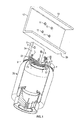
- Figs. 1 and 2 show the components which comprise the assembly system according to the invention.
- the object is to establish a simple, fast and safe method of assembling an air tank 20 for a chassis frame 10, 12 on a vehicle.
- Tank 20 is an air-filled tank with bellows below so that the bottom is able to absorb impacts and vibrations and transmit them to the air in the tank for the purpose of damping the effect of the chassis.
- Tank 20 is cylindrical in shape on the side, whilst at the top it rounds to form a curved transition 22 which is shaped along a circular opening to form a circular edge 21.
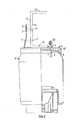
- FIG. 2 The joint between tank 20 and plate 4 is shown in Fig. 2 .
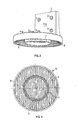
- plate 4 is a circular disc which is provided both with an outer edge 8 and with a circular recess 7, which is dimensioned to be able to engage with a tight fit with edge 21 of the tank, as sown in Fig. 2 .
- the latter is curved on the underside to correspond with curvature 22 of the tank. This provides secure positioning of the tank and the transmission of force from the tank to the plate is rendered precise without displacements.
- transverse ribs 9 whose purpose is to stiffen the plate and hence render it suitable for absorbing compressive stresses from tank 20, are formed on the underside of plate 4, as shown in Figs. 3 and 4 ,
- an air connection socket 5 which is designed to be able to be connected to a compressed air hose for filling the tank with air, is fitted inside projection 7 on plate 4. Socket 5 is preferably cast onto plate 4.
- a snap coupling 30, or possibly a threaded joint, may be formed on socket 5 for securing the hose.
- a non-return valve is built into the socket.
- plate 4 On the upper side plate 4 lies flush against bottom side 10 of the chassis frame. In this embodiment plate 4 will therefore be provided with holes, not shown, for bolts which can be screwed into frame 10.
- plate 4 is provided with a vertical rear wall 2, which is flush 2a to the rear side 12 of the chassis frame, as shown in Fig. 2 .
- Holes are first marked out for the bolts, which can be screwed through the frame, possibly by cutting a thread for fitting the plate.
- Air tank 20 can then be mounted by pressing it upwards until edge section 21 engages with recess 7 on the retainer.
- the plate will preferably be made of plastic which, because of its relative softness, will have a damping effect and will be completely without risk of corrosion.
Landscapes
- Engineering & Computer Science (AREA)
- General Engineering & Computer Science (AREA)
- Mechanical Engineering (AREA)
- Body Structure For Vehicles (AREA)
- Vehicle Body Suspensions (AREA)
Abstract
Description
- The invention relates to an assembly system for assembling pneumatic suspension components for a chassis frame on a vehicle, which components comprise an airtight tank with a compressed air connection at the top and with a lower flexible bottom which is blocked off from the tank by means of bellows, wherein the tank has an opening at the top whose edge section is able to grip a recess projecting from the underside of a retaining plate and is secured in a snap lock joint, which retaining plate is provided with means for securing to the chassis frame.
- Suspension systems of this type are generally used for the suspension/vibration damping of vehicles such as trucks, buses, trailers and corresponding mobile units.
-
US 6,926,264 B1 discloses an assembly system comprising an airtight tank (14) with a compressed air connection at the top (23), a lower flexible bottom (4) and bellows (5), which top tank (14) has an opening with an edge section which can grip a recess projecting from the underside of a retaining plate (12) to form a snap lock assembly, which retaining plate (12) is provided with means (24, 26, 27, 13) for securing to the chassis frame. - This is a difficult, time-consuming process which also generates noise if the fittings become loose.
- The object of the invention is to simplify and improve assembly systems of this type and it is achieved according to the invention in that the retaining plate is provided with a back piece which runs perpendicular to the plate to form a contact surface that can rest against the vertical part of the frame and secured to it.
- Because the retaining plate is provided with a vertical upright assembly part, it could be assembled by supporting it against the rear side of the chassis frame in a solid manner that can be carried out quickly.
- By mounting the plate either secured to the horizontal or vertical part of the chassis frame by bolted joints of prior art, as mentioned in
claim 2, this assembly could be achieved by anyone without the need for special tools. - By providing the underside of the plate with stiffening ribs, as mentioned in
claim 3, the plate is given a high degree of stability and there is a saving in material during production. - By adapting the shape between the top of the tank and the bottom of the plate, as mentioned in
claim 4, so that the tank curves from its lateral wall to its top, a high degree of stability is achieved for a solid, unshakeable and compact assembly of these two components. - By providing the plate with a connection socket, as mentioned in
claim 5, the air feed pipe can easily be established by means of a snap or threaded joint. - Finally, as mentioned in claim 6, it is appropriate to manufacture the plate from plastic to provide a strong, vibration-free component that will contribute to damping vibrations due to the relative softness of the material.
- An example of an embodiment of the invention will be described in more detail in the following with reference to the drawing, in which
-
Fig. 1 shows the components inside the assembly, viewed in partial cross-section, -
Fig. 2 shows the components viewed assembled in partial cross-section, -
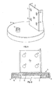
Fig. 3 shows the plate with the upright assembly wall viewed in perspective, -
Fig. 4 shows the plate viewed from below, -
Fig. 5 shows the plate with the connection socket fitted, and -
Fig. 6 shows a sectional view of the plate. -
Figs. 1 and2 show the components which comprise the assembly system according to the invention. - The object is to establish a simple, fast and safe method of assembling an
air tank 20 for achassis frame -
Tank 20 is an air-filled tank with bellows below so that the bottom is able to absorb impacts and vibrations and transmit them to the air in the tank for the purpose of damping the effect of the chassis. -
Tank 20 is cylindrical in shape on the side, whilst at the top it rounds to form acurved transition 22 which is shaped along a circular opening to form acircular edge 21. - The joint between
tank 20 andplate 4 is shown inFig. 2 . - As shown in
Figs. 3-5 ,plate 4 is a circular disc which is provided both with anouter edge 8 and with acircular recess 7, which is dimensioned to be able to engage with a tight fit withedge 21 of the tank, as sown inFig. 2 . - To ensure good contact between the upper part of the tank and the plate, the latter is curved on the underside to correspond with
curvature 22 of the tank. This provides secure positioning of the tank and the transmission of force from the tank to the plate is rendered precise without displacements. - Moreover,
transverse ribs 9, whose purpose is to stiffen the plate and hence render it suitable for absorbing compressive stresses fromtank 20, are formed on the underside ofplate 4, as shown inFigs. 3 and 4 , - Finally, an
air connection socket 5, which is designed to be able to be connected to a compressed air hose for filling the tank with air, is fitted insideprojection 7 onplate 4.Socket 5 is preferably cast ontoplate 4. - For this purpose a
snap coupling 30, or possibly a threaded joint, may be formed onsocket 5 for securing the hose. A non-return valve is built into the socket. - On the
upper side plate 4 lies flush againstbottom side 10 of the chassis frame. In thisembodiment plate 4 will therefore be provided with holes, not shown, for bolts which can be screwed intoframe 10. - In the example shown
plate 4 is provided with a verticalrear wall 2, which isflush 2a to therear side 12 of the chassis frame, as shown inFig. 2 . - In the embodiment shown there are four
holes 11 drilled through the wall for a bolted joint. - The assembly work will now be described.
- Holes are first marked out for the bolts, which can be screwed through the frame, possibly by cutting a thread for fitting the plate.
-
Air tank 20 can then be mounted by pressing it upwards untiledge section 21 engages withrecess 7 on the retainer. - Since the parts are shaped into a snap lock, the assembly will be carried out both easily and quickly.
- The plate will preferably be made of plastic which, because of its relative softness, will have a damping effect and will be completely without risk of corrosion.
- It will be correspondingly easy to remove the tank by suitably pulling it down until the coupling is disengaged. This considerably facilitates service work without requiring tools.
Claims (6)
- An assembly system for assembling pneumatic suspension components for a chassis frame on a vehicle, which components comprise an airtight tank with a compressed air connection at top and with a lower flexible bottom which is blocked off from the tank by means of bellows, wherein the tank has at the top an opening whose edge section is able to grip a recess projecting from an underside of a retaining plate, thereby securing it in a snap lock joint, which retaining plate is provided with means for securing to the chassis frame, characterised in that the retaining plate (4) is provided with a back piece (2) which runs perpendicular to the plate (4) to form a contact surface (2a) which may rest against the vertical part (12) of the frame and can be secured to it,
- The assembly system according to claim 1, characterised in that the fastening means consists of fastening means of prior art, such as a bolted joint via holes (3, 11).
- The assembly system according to claims 1 and 2, characterised in that the underside of the plate (4) resting against the tanks (20) is provided with stiffening ribs (9).
- The assembly system according to claims 1-3, characterised in that the upper edge section (22) of the tanks (20) is rounded from the lateral wall against the edge section (21) to rest against the underside of the plate (4), which is correspondingly hollowed out (9) to form a common surface of contact and support.
- The assembly system according to claims 1-4, characterised in that an air connection socket (5) is formed in the plate (4) with connection to the inside of the tank (20), to which socket can be connected to an air hose by means of a threaded joint or snap coupling (30).
- The assembly system according to claims 1-5, characterised in that the plate (4) with the socket (5) is manufactured by casting in plastic.
Applications Claiming Priority (1)
| Application Number | Priority Date | Filing Date | Title |
|---|---|---|---|
| DK201400530 DK178600B1 (en) | 2014-09-18 | 2014-09-18 | MOUNTING SYSTEM FOR FITTING SPRING COMPONENTS ON A VEHICLE |
Publications (1)
| Publication Number | Publication Date |
|---|---|
| EP2998136A1 true EP2998136A1 (en) | 2016-03-23 |
Family
ID=54557358
Family Applications (1)
| Application Number | Title | Priority Date | Filing Date |
|---|---|---|---|
| EP15388003.4A Withdrawn EP2998136A1 (en) | 2014-09-18 | 2015-09-15 | Assembly system for assembling suspension components on a vehicle |
Country Status (2)
| Country | Link |
|---|---|
| EP (1) | EP2998136A1 (en) |
| DK (1) | DK178600B1 (en) |
Cited By (1)
| Publication number | Priority date | Publication date | Assignee | Title |
|---|---|---|---|---|
| US11472247B2 (en) * | 2019-10-01 | 2022-10-18 | Firestone Industrial Products Company, Llc | Mounting bracket assemblies as well as suspension assemblies, kits and methods including same |
Citations (4)
| Publication number | Priority date | Publication date | Assignee | Title |
|---|---|---|---|---|
| WO2001033101A1 (en) * | 1999-10-22 | 2001-05-10 | Bfs Diversified Products, Llc | Integral bracket and end mounting plate for air spring |
| FR2827551A3 (en) * | 2001-07-20 | 2003-01-24 | Cf Gomma Spa | Upper assembly for motor vehicle suspension system pneumatic spring has plastic plate with thrust surface for membrane, coupling member and connector |
| US6926264B1 (en) * | 1999-05-28 | 2005-08-09 | The Goodyear Tire & Rubber Company | Air spring upper retainer |
| US20140061983A1 (en) * | 2012-08-31 | 2014-03-06 | Firestone Industrial Products Company, Llc | End members and gas spring assemblies including same |
Family Cites Families (3)
| Publication number | Priority date | Publication date | Assignee | Title |
|---|---|---|---|---|
| US6386524B1 (en) * | 2000-02-15 | 2002-05-14 | Bfs Diversified Products, Llc | Pedestal mounted full reservoir air spring piston |
| US8371596B2 (en) * | 2009-05-13 | 2013-02-12 | Saf-Holland, Inc. | Suspension system for heavy and vocational vehicles |
| DE102010016768A1 (en) * | 2010-05-04 | 2011-11-10 | Contitech Luftfedersysteme Gmbh | Air spring arrangement for a commercial vehicle |
-
2014
- 2014-09-18 DK DK201400530 patent/DK178600B1/en not_active IP Right Cessation
-
2015
- 2015-09-15 EP EP15388003.4A patent/EP2998136A1/en not_active Withdrawn
Patent Citations (4)
| Publication number | Priority date | Publication date | Assignee | Title |
|---|---|---|---|---|
| US6926264B1 (en) * | 1999-05-28 | 2005-08-09 | The Goodyear Tire & Rubber Company | Air spring upper retainer |
| WO2001033101A1 (en) * | 1999-10-22 | 2001-05-10 | Bfs Diversified Products, Llc | Integral bracket and end mounting plate for air spring |
| FR2827551A3 (en) * | 2001-07-20 | 2003-01-24 | Cf Gomma Spa | Upper assembly for motor vehicle suspension system pneumatic spring has plastic plate with thrust surface for membrane, coupling member and connector |
| US20140061983A1 (en) * | 2012-08-31 | 2014-03-06 | Firestone Industrial Products Company, Llc | End members and gas spring assemblies including same |
Cited By (2)
| Publication number | Priority date | Publication date | Assignee | Title |
|---|---|---|---|---|
| US11472247B2 (en) * | 2019-10-01 | 2022-10-18 | Firestone Industrial Products Company, Llc | Mounting bracket assemblies as well as suspension assemblies, kits and methods including same |
| US11897299B2 (en) | 2019-10-01 | 2024-02-13 | Firestone Industrial Products Company, Llc | Mounting bracket assemblies as well as suspension assemblies, kits and methods including same |
Also Published As
| Publication number | Publication date |
|---|---|
| DK178600B1 (en) | 2016-08-08 |
| DK201400530A1 (en) | 2016-04-04 |
Similar Documents
| Publication | Publication Date | Title |
|---|---|---|
| JP5410639B2 (en) | Mounting device for vehicle | |
| US20140356063A1 (en) | Fastening device | |
| EP3127733B1 (en) | A powertrain mount assembly | |
| KR102522291B1 (en) | Suspension apparatus for vehicle | |
| MX2008010728A (en) | Transmission mount assembly. | |
| US20170106709A1 (en) | Support with Air Equalization Container | |
| US9707905B2 (en) | Reinforcement for pickup truck floor pan | |
| EP2998136A1 (en) | Assembly system for assembling suspension components on a vehicle | |
| US10442286B2 (en) | Integrated bracket for automotive heat exchanger | |
| US9527360B2 (en) | Refurbishment assembly for heavy duty chassis and method | |
| WO2021090391A1 (en) | Outdoor unit of air conditioner and method for assembling outdoor unit of air conditioner | |
| US9102353B2 (en) | Mounting arrangement for steering pump | |
| US20140252704A1 (en) | Engine mount structure for apparatus equipped with engine | |
| JP2010241288A (en) | Device and method for mounting air reservoir tank | |
| CN206031262U (en) | Pipeline fixing device and have its vehicle | |
| CN203995638U (en) | A kind of Engine Mounting System | |
| EP2199167B1 (en) | Fastening system for compressed air reservoir for industrial or commercial vehicle | |
| CN108349344B (en) | Removable aids for installation and adjustment of vehicle axle buffers | |
| CN204055351U (en) | A kind of gear box suspension mounting structure | |
| CN203372221U (en) | Vacuum pump support assembly and automobile | |
| US20160101687A1 (en) | Fuel tank coupling assembly | |
| CN105438102A (en) | Protection device for front lower part of truck | |
| CN221004207U (en) | Pipe joint structure | |
| US20180118020A1 (en) | Storage container with improved mounting assembly | |
| CN203395064U (en) | Vibration reduction isolation assembly and corresponding vehicle |
Legal Events
| Date | Code | Title | Description |
|---|---|---|---|
| PUAI | Public reference made under article 153(3) epc to a published international application that has entered the european phase |
Free format text: ORIGINAL CODE: 0009012 |
|
| AK | Designated contracting states |
Kind code of ref document: A1 Designated state(s): AL AT BE BG CH CY CZ DE DK EE ES FI FR GB GR HR HU IE IS IT LI LT LU LV MC MK MT NL NO PL PT RO RS SE SI SK SM TR |
|
| AX | Request for extension of the european patent |
Extension state: BA ME |
|
| 17P | Request for examination filed |
Effective date: 20160923 |
|
| RBV | Designated contracting states (corrected) |
Designated state(s): AL AT BE BG CH CY CZ DE DK EE ES FI FR GB GR HR HU IE IS IT LI LT LU LV MC MK MT NL NO PL PT RO RS SE SI SK SM TR |
|
| STAA | Information on the status of an ep patent application or granted ep patent |
Free format text: STATUS: EXAMINATION IS IN PROGRESS |
|
| 17Q | First examination report despatched |
Effective date: 20180702 |
|
| STAA | Information on the status of an ep patent application or granted ep patent |
Free format text: STATUS: THE APPLICATION IS DEEMED TO BE WITHDRAWN |
|
| 18D | Application deemed to be withdrawn |
Effective date: 20181113 |