EP2998071B1 - Wrench with a lockable torque-setting mechanism - Google Patents
Wrench with a lockable torque-setting mechanism Download PDFInfo
- Publication number
- EP2998071B1 EP2998071B1 EP14185438.0A EP14185438A EP2998071B1 EP 2998071 B1 EP2998071 B1 EP 2998071B1 EP 14185438 A EP14185438 A EP 14185438A EP 2998071 B1 EP2998071 B1 EP 2998071B1
- Authority
- EP
- European Patent Office
- Prior art keywords
- torque
- lever
- pawl
- teeth
- setting mechanism
- Prior art date
- Legal status (The legal status is an assumption and is not a legal conclusion. Google has not performed a legal analysis and makes no representation as to the accuracy of the status listed.)
- Active
Links
- 230000007246 mechanism Effects 0.000 title claims description 49
- 238000005096 rolling process Methods 0.000 description 3
- 238000003780 insertion Methods 0.000 description 2
- 230000037431 insertion Effects 0.000 description 2
- 230000000903 blocking effect Effects 0.000 description 1
Images


Classifications
-
- B—PERFORMING OPERATIONS; TRANSPORTING
- B25—HAND TOOLS; PORTABLE POWER-DRIVEN TOOLS; MANIPULATORS
- B25B—TOOLS OR BENCH DEVICES NOT OTHERWISE PROVIDED FOR, FOR FASTENING, CONNECTING, DISENGAGING OR HOLDING
- B25B23/00—Details of, or accessories for, spanners, wrenches, screwdrivers
- B25B23/14—Arrangement of torque limiters or torque indicators in wrenches or screwdrivers
- B25B23/142—Arrangement of torque limiters or torque indicators in wrenches or screwdrivers specially adapted for hand operated wrenches or screwdrivers
- B25B23/1422—Arrangement of torque limiters or torque indicators in wrenches or screwdrivers specially adapted for hand operated wrenches or screwdrivers torque indicators or adjustable torque limiters
- B25B23/1427—Arrangement of torque limiters or torque indicators in wrenches or screwdrivers specially adapted for hand operated wrenches or screwdrivers torque indicators or adjustable torque limiters by mechanical means
Definitions
- the present invention relates to a wrench equipped with a torque-setting mechanism and, more particularly, to a wrench equipped with a lockable torque-setting mechanism.
- Wrenches are used to exert torque on fasteners such as threaded bolts and nuts to fasten work-pieces. It is important to exert a proper value of torque. In some applications, it is particularly important to have the value of torque close to but under a limit to effectively fasten the work-pieces without the risks of damaging the work-pieces.
- Some wrenches are equipped with torque-setting mechanisms. Such a torque-setting mechanism is used to set a maximum value of torque that can be exerted via such a wrench.
- a typical torque-setting mechanism includes a knob connected to a handle of a wrench. The maximum value of torque is set by rotating the knob relative to the handle. The knob might however be accidentally rotated relative to the handle in operation.
- the knob is formed with teeth for engagement with teeth formed on the handle.
- the knob can be translated relative to the handle between two positions. In the first position, the teeth of the knob are engaged with the teeth of the handle so that the knob cannot be rotated relative to the handle. In the second position, the teeth of the knob are disengaged from the teeth of the handle so that the knob can be rotated relative to the handle. The knob might however be excessively translated and hence removed from the handle.
- a spring-biased detent is connected to the knob and a recess is made in the handle.
- the spring-biased detent is intended for insertion in the recess to keep the knob connected to the handle.
- the insertion of the spring-biased detent in the recess has however been proven to be ineffective to keep the knob connected to the handle.
- a locking mechanism of a wrench that comprises a grip as well as two sleeves arranged in the grip and being capable of engaging each other through teeth formed on their axial surfaces facing the other sleeve, respectively.
- the two sleeves are engaged with each other by pivoting a switch, thereby blocking a rotation of the grip.
- the two sleeves are disengaged by pivoting the switch back so as to allow for the grip to be rotated.
- the present invention is intended to obviate or at least alleviate the problems encountered in prior art.
- the lockable torque-setting mechanism includes a locking mechanism.
- the locking mechanism includes a sleeve, a body, a pawl and a lever.
- the sleeve is non-movably connected to a grip of the wrench and formed with teeth.
- the body is non-movably connected to a knob, partially inserted in the sleeve, and includes a recess in communication with a cavity.
- the pawl is movably inserted in the recess and formed with teeth.
- the lever includes an end for pressing the pawl and another end pivotally connected to the body.
- the lever is movable in the cavity of the body between a first position to press a first portion of the pawl to engage the teeth of the pawl with the teeth of the sleeve and a second position to press a second portion of the pawl to disengage the teeth of the pawl from the teeth of the sleeve.
- the wrench 100 includes a head 10, a grip 40, a torque-relaying mechanism 102 for delivering torque to the head 10 from the grip 40, a torque-setting mechanism 101 operable for setting a maximum value of torque deliverable via the torque-relaying mechanism 102, and a locking mechanism (not numbered) operable for locking the torque-setting mechanism 101.
- the head 10 is operatively connected to an insert 11 via a ratchet mechanism that is not shown for being conventional.
- the grip 40 is a tubular element with two windows 42 and 49 made in the periphery.
- a lens 21 is attached to the grip 40 to cover the window 42.
- the lens 21 is made or printed with a scale.
- the scale includes two unit systems such as lb-ft and N-m.
- a lens 29 is attached to the grip 40 to cover the window 49.
- the torque-setting mechanism 101 includes a threaded rod 34, a threaded sleeve 35, a bearing 38, a knob 70 and an indicator 28.
- the threaded rod 34 is connected to the knob 70.
- the threaded rod 34 can be rotated but cannot be translated in the grip 40.
- the threaded sleeve 35 can be translated but cannot be rotated in the grip 40.
- the threaded sleeve 35 is engaged with the threaded rod 34.
- the knob 70 is operable to rotate the threaded rod 34 to translate the threaded sleeve 35.
- the indicator 28 is connected to the threaded sleeve 35 so that they can be translated together.
- the indicator 28 is observable via the lens 21.
- the position of the indicator 28 relative to the scale made or printed on the lens 21 represents the maximum value of torque set by the torque-setting mechanism.
- the torque-relaying mechanism 102 includes a shank 20, a lever 30, a rolling unit 32 and a spring 36.
- the spring 36 is compressed between the threaded sleeve 35 and the rolling unit 32.
- the rolling unit 32 is in detachable contact with an inclined face formed at an end of the lever 30.
- the lever 30 is pivotally inserted in the shank 20, which is connected to the grip 40.
- the head 10 is formed at another end of the lever 30.
- the locking mechanism includes a sleeve 44, a body 50, a lever 60, a spring 64, two caps 63, two pawls 65 and a switch 72.
- Each of the pawls 65 is formed with teeth 66.
- the sleeve 44 includes an axial space 41, two radial apertures 47 and 48 and teeth 46.
- the axial space 41 includes a large portion 43 and a small portion 45, with a shoulder formed between them.
- the large portion 43 of the axial space 41 is in communication with the radial aperture 47.
- the small portion 45 of the axial space 41 is in communication with the radial aperture 48.
- the teeth 46 are formed on an internal face of the sleeve 44, in the small portion 45 of the axial space 41.
- the body 50 includes two axial cavities 51 and 58, a neck 52 formed at an end, an annular flange 54 formed near the neck 52, and two recesses 53 made near the annular flange 54.
- the axial cavity 58 is made in the neck 52.
- the recesses 53 are in communication with the axial cavity 58 via a bore 55.
- the recess 53, the bore 55 and the axial cavity 58 together form a T-shaped channel.
- the body 50 further includes an axial aperture 56 in communication with the axial cavity 51.
- the body 50 includes two more radial apertures 59 in communication with the axial cavity 58.
- Two screw holes 57 are made in the annular flange 54.
- the knob 70 includes two axial cavities 71 and 75, an axial bore 78 via which the axial cavity 71 is in communication with the axial cavity 75, and a countersink hole 73.
- the knob 70 further includes teeth 76 formed on an internal face, in the axial cavity 75.
- a scale ring 22 includes a scale 24 formed or printed with on an external face and teeth 26 formed on the external face.
- the scale 24 includes smaller units than the scale formed or printed on the lens 21.
- the sleeve 44 is secured to the shank 20 via a screw (not numbered).
- the scale ring 22 is placed on the sleeve 44.
- the pawls 65 are placed in the recesses 53 and pivotally connected to the annular flange 54 by two pins 68.
- the body 50 except the annular flange 54 and the neck 52, is inserted in the sleeve 44.
- the teeth 66 of the pawls 65 can be engaged with the teeth 46 of the sleeve 44.
- the spring 64 includes a middle portion inserted in an aperture 62 made in the lever 60 and two ends inserted in the caps 63.
- the lever 60 includes a portion inserted in the axial cavity 58 and the bore 55 of the body 50.
- a pin 67 is inserted in the radial apertures 59 of the neck 52 and an aperture 61 made in the lever 60 to pivotally connect the lever 60 to the body 50.
- the caps 63 are in contact with the pawls 65.
- the lever 60 includes another portion inserted in axial bore 78 of the knob 70.
- a screw 74 is inserted in the lever 60 via an axial aperture (not numbered) made in the switch 72 to connect the switch 72 to the lever 60.
- a screw (not shown) is inserted in the countersink hole 73 of the knob 70 and one of the screw holes 57 of the body 50 to connect the knob 70 to the body 50 so that they are rotatable together.
- the switch 72 is pivoted into a first position like a seesaw.
- the lever 60 is pivoted into a first position.
- Each of the caps 63 is abutted against a first portion of a corresponding one of the pawls 65 so that the teeth 66 of the pawls 65 are engaged with the teeth 46 of the sleeve 44.
- the body 50 cannot be rotated relative to the sleeve 44. Therefore, the knob 70 cannot be rotated relative to the shank 20.
- the switch 72 is switched into a second position.
- the lever 60 is pivoted into a second position.
- Each of the caps 63 is abutted against a second portion of a corresponding one of the pawls 65 so that the teeth 66 of the pawls 65 are disengaged from the teeth 46 of the sleeve 44.
- the body 50 can be rotated relative to the sleeve 44.
- the knob 70 can be rotated relative to the shank 20.
- FIGS. 14 to 16 there is a locking mechanism operable for locking a torque-setting mechanism of a wrench according to a second embodiment of the present invention.
- the second embodiment is like the first embodiment except several features.
- a switch 80 that can be translated relative to the grip 40 is used instead of the switch 72 that can be pivoted relative to the grip 40.
- the switch 80 includes a bore 82 for receiving an end of the lever 60.
- the lever 60 can be translated, instead of pivoted, relative to the body 50.
- the axial cavity 58 is a groove adapted for movably receiving an end of the lever 60.
- the neck 52 is made with two slots 90 for movably receiving two bosses 92 formed on the lever 60.
Landscapes
- Engineering & Computer Science (AREA)
- Mechanical Engineering (AREA)
- Details Of Spanners, Wrenches, And Screw Drivers And Accessories (AREA)
Description
- The present invention relates to a wrench equipped with a torque-setting mechanism and, more particularly, to a wrench equipped with a lockable torque-setting mechanism.
- Wrenches are used to exert torque on fasteners such as threaded bolts and nuts to fasten work-pieces. It is important to exert a proper value of torque. In some applications, it is particularly important to have the value of torque close to but under a limit to effectively fasten the work-pieces without the risks of damaging the work-pieces.
- Some wrenches are equipped with torque-setting mechanisms. Such a torque-setting mechanism is used to set a maximum value of torque that can be exerted via such a wrench. A typical torque-setting mechanism includes a knob connected to a handle of a wrench. The maximum value of torque is set by rotating the knob relative to the handle. The knob might however be accidentally rotated relative to the handle in operation.
- In another conventional torque-setting mechanism, the knob is formed with teeth for engagement with teeth formed on the handle. The knob can be translated relative to the handle between two positions. In the first position, the teeth of the knob are engaged with the teeth of the handle so that the knob cannot be rotated relative to the handle. In the second position, the teeth of the knob are disengaged from the teeth of the handle so that the knob can be rotated relative to the handle. The knob might however be excessively translated and hence removed from the handle.
- In another conventional torque-setting mechanism, a spring-biased detent is connected to the knob and a recess is made in the handle. The spring-biased detent is intended for insertion in the recess to keep the knob connected to the handle. The insertion of the spring-biased detent in the recess has however been proven to be ineffective to keep the knob connected to the handle.
- In another conventional torque-setting mechanism as disclosed in Taiwanese Patent M371616 issued to the present applicant, the handle is made with an adequate length to keep the knob connected to the handle should the spring-biased detent be removed out of the recess again. The long handle is however unreliable.
- From the publication of European patent application
EP 1 375 072 A2 a locking mechanism of a wrench is known that comprises a grip as well as two sleeves arranged in the grip and being capable of engaging each other through teeth formed on their axial surfaces facing the other sleeve, respectively. For locking the grip in a particular rotational position, i.e. for keeping a particular torque setting, the two sleeves are engaged with each other by pivoting a switch, thereby blocking a rotation of the grip. For torque adjustment the two sleeves are disengaged by pivoting the switch back so as to allow for the grip to be rotated. - Therefore, the present invention is intended to obviate or at least alleviate the problems encountered in prior art.
- It is the primary objective of the present invention to provide a wrench with a reliable lockable torque-setting mechanism.
- To achieve the foregoing objective, the lockable torque-setting mechanism includes a locking mechanism. The locking mechanism includes a sleeve, a body, a pawl and a lever. The sleeve is non-movably connected to a grip of the wrench and formed with teeth. The body is non-movably connected to a knob, partially inserted in the sleeve, and includes a recess in communication with a cavity. The pawl is movably inserted in the recess and formed with teeth. The lever includes an end for pressing the pawl and another end pivotally connected to the body. The lever is movable in the cavity of the body between a first position to press a first portion of the pawl to engage the teeth of the pawl with the teeth of the sleeve and a second position to press a second portion of the pawl to disengage the teeth of the pawl from the teeth of the sleeve.
- Other objectives, advantages and features of the present invention will be apparent from the following description referring to the attached drawings.
- The present invention will be described via detailed illustration of two embodiments referring to the drawings wherein:
-
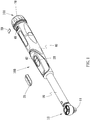
FIG. 1 is a perspective view of a wrench equipped with a lockable torque-setting mechanism according to the first embodiment of the present invention; -
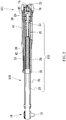
FIG. 2 is a cross-sectional view of the wrench shown inFIG. 1 ; -
FIG. 3 is an enlarged partial view of the wrench shown inFIG. 2 ; -
FIG. 4 is an exploded view of the wrench shown inFIG. 3 ; -
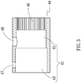
FIG. 5 is an enlarged view of a sleeve used in the wrench shown inFIG. 2 ; -
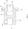
FIG. 6 is an enlarged view of a body used in the wrench shown inFIG. 2 ; -
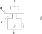
FIG. 7 is a side view of the body shown inFIG. 6 ; -
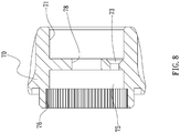
FIG. 8 is an enlarged view of a knob used in the wrench shown inFIG. 2 ; -
FIG. 9 is an enlarged perspective view of a scale ring used in the wrench shown inFIG. 2 ; -
FIG. 10 is a side view of a combination of a switch with the sleeve shown inFIG. 5 and the body shown inFIGS. 6 and7 ; -
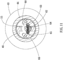
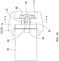
FIG. 11 is a cross-sectional view of the combination illustrated inFIG. 10 ; -
FIG. 12 is a side view of the combination in another position than shown inFIG. 10 ; -
FIG. 13 is a cross-sectional view of the combination illustrated inFIG. 12 ; -
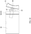
FIG. 14 is a cross-sectional view of a lockable torque-setting mechanism according to the second embodiment of the present invention; -
FIG. 15 is a cross-sectional view of the lockable torque-setting mechanism in another position than shown inFIG. 14 ; and -
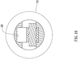
FIG. 16 is another cross-sectional view of the lockable torque-setting mechanism shown inFIG. 15 . - Referring to
FIGS. 1 through 13 , there is awrench 100 according to a first embodiment of the present invention. Thewrench 100 includes ahead 10, agrip 40, a torque-relaying mechanism 102 for delivering torque to thehead 10 from thegrip 40, a torque-setting mechanism 101 operable for setting a maximum value of torque deliverable via the torque-relaying mechanism 102, and a locking mechanism (not numbered) operable for locking the torque-setting mechanism 101. Thehead 10 is operatively connected to aninsert 11 via a ratchet mechanism that is not shown for being conventional. - The
grip 40 is a tubular element with twowindows lens 21 is attached to thegrip 40 to cover thewindow 42. Thelens 21 is made or printed with a scale. The scale includes two unit systems such as lb-ft and N-m. Alens 29 is attached to thegrip 40 to cover thewindow 49. - The torque-
setting mechanism 101 includes a threadedrod 34, a threadedsleeve 35, abearing 38, aknob 70 and anindicator 28. The threadedrod 34 is connected to theknob 70. The threadedrod 34 can be rotated but cannot be translated in thegrip 40. The threadedsleeve 35 can be translated but cannot be rotated in thegrip 40. The threadedsleeve 35 is engaged with the threadedrod 34. Thus, theknob 70 is operable to rotate the threadedrod 34 to translate the threadedsleeve 35. Theindicator 28 is connected to the threadedsleeve 35 so that they can be translated together. Theindicator 28 is observable via thelens 21. The position of theindicator 28 relative to the scale made or printed on thelens 21 represents the maximum value of torque set by the torque-setting mechanism. - The torque-relaying
mechanism 102 includes ashank 20, alever 30, a rollingunit 32 and aspring 36. Thespring 36 is compressed between the threadedsleeve 35 and the rollingunit 32. The rollingunit 32 is in detachable contact with an inclined face formed at an end of thelever 30. Thelever 30 is pivotally inserted in theshank 20, which is connected to thegrip 40. Thehead 10 is formed at another end of thelever 30. - The structures and operations of the torque-setting
mechanism 101 and the torque-relayingmechanism 102 will not be provided because they can be found inUS Patent No. 7182006 . - The locking mechanism includes a
sleeve 44, abody 50, alever 60, aspring 64, twocaps 63, twopawls 65 and aswitch 72. Each of thepawls 65 is formed withteeth 66. - Referring to
FIG. 5 , thesleeve 44 includes anaxial space 41, tworadial apertures teeth 46. Theaxial space 41 includes alarge portion 43 and asmall portion 45, with a shoulder formed between them. Thelarge portion 43 of theaxial space 41 is in communication with theradial aperture 47. Thesmall portion 45 of theaxial space 41 is in communication with theradial aperture 48. Theteeth 46 are formed on an internal face of thesleeve 44, in thesmall portion 45 of theaxial space 41. - Referring to
FIGS. 6 and7 , thebody 50 includes twoaxial cavities neck 52 formed at an end, anannular flange 54 formed near theneck 52, and tworecesses 53 made near theannular flange 54. Theaxial cavity 58 is made in theneck 52. Therecesses 53 are in communication with theaxial cavity 58 via abore 55. Therecess 53, thebore 55 and theaxial cavity 58 together form a T-shaped channel. Thebody 50 further includes anaxial aperture 56 in communication with theaxial cavity 51. Thebody 50 includes two moreradial apertures 59 in communication with theaxial cavity 58. Two screw holes 57 are made in theannular flange 54. - Referring to
FIG. 8 , theknob 70 includes twoaxial cavities axial bore 78 via which theaxial cavity 71 is in communication with theaxial cavity 75, and acountersink hole 73. Theknob 70 further includesteeth 76 formed on an internal face, in theaxial cavity 75. - Referring to
FIG. 9 , ascale ring 22 includes ascale 24 formed or printed with on an external face andteeth 26 formed on the external face. Thescale 24 includes smaller units than the scale formed or printed on thelens 21. - Referring to
FIGS. 3 and4 , thesleeve 44 is secured to theshank 20 via a screw (not numbered). Thescale ring 22 is placed on thesleeve 44. Thepawls 65 are placed in therecesses 53 and pivotally connected to theannular flange 54 by twopins 68. Thebody 50, except theannular flange 54 and theneck 52, is inserted in thesleeve 44. Theteeth 66 of thepawls 65 can be engaged with theteeth 46 of thesleeve 44. - The
spring 64 includes a middle portion inserted in anaperture 62 made in thelever 60 and two ends inserted in thecaps 63. Thelever 60 includes a portion inserted in theaxial cavity 58 and thebore 55 of thebody 50. Apin 67 is inserted in theradial apertures 59 of theneck 52 and anaperture 61 made in thelever 60 to pivotally connect thelever 60 to thebody 50. Thecaps 63 are in contact with thepawls 65. Thelever 60 includes another portion inserted inaxial bore 78 of theknob 70. Ascrew 74 is inserted in thelever 60 via an axial aperture (not numbered) made in theswitch 72 to connect theswitch 72 to thelever 60. A screw (not shown) is inserted in thecountersink hole 73 of theknob 70 and one of the screw holes 57 of thebody 50 to connect theknob 70 to thebody 50 so that they are rotatable together. - Referring to
FIGS. 10 and11 , theswitch 72 is pivoted into a first position like a seesaw. Thus, thelever 60 is pivoted into a first position. Each of thecaps 63 is abutted against a first portion of a corresponding one of thepawls 65 so that theteeth 66 of thepawls 65 are engaged with theteeth 46 of thesleeve 44. Thebody 50 cannot be rotated relative to thesleeve 44. Therefore, theknob 70 cannot be rotated relative to theshank 20. - Referring to
FIGS. 12 and13 , theswitch 72 is switched into a second position. Thelever 60 is pivoted into a second position. Each of thecaps 63 is abutted against a second portion of a corresponding one of thepawls 65 so that theteeth 66 of thepawls 65 are disengaged from theteeth 46 of thesleeve 44. Thebody 50 can be rotated relative to thesleeve 44. Hence, theknob 70 can be rotated relative to theshank 20. - Referring to
FIGS. 14 to 16 , there is a locking mechanism operable for locking a torque-setting mechanism of a wrench according to a second embodiment of the present invention. The second embodiment is like the first embodiment except several features. Firstly, aswitch 80 that can be translated relative to thegrip 40 is used instead of theswitch 72 that can be pivoted relative to thegrip 40. Theswitch 80 includes abore 82 for receiving an end of thelever 60. Secondly, thelever 60 can be translated, instead of pivoted, relative to thebody 50. Accordingly, theaxial cavity 58 is a groove adapted for movably receiving an end of thelever 60. Moreover, theneck 52 is made with twoslots 90 for movably receiving twobosses 92 formed on thelever 60. - The present invention has been described via the detailed illustration of the embodiments. Those skilled in the art can derive variations from the embodiments without departing from the scope of the present invention. Therefore, the embodiments shall not limit the scope of the present invention defined in the claims.
Claims (13)
- A locking mechanism for locking a knob (70) relative to a grip (40), the locking mechanism including
a sleeve (44) non-movably connected to the grip (40) and formed with teeth (46)
characterised in that
the locking mechanism further includes a body (50) non-movably connected to the knob (70), partially inserted in the sleeve (44), and formed with at least one recess (53) and a cavity (58) in communication with the recess (53);
at least one pawl (65) movably inserted in the recess (53) and formed with teeth (66); and
a lever (60) formed with an end for abutment against the pawl (65) and movable in the cavity (58) of the body (50) between a first position to press a first portion of the pawl (65) to engage the teeth (66) of the pawl (65) with the teeth (46) of the sleeve (44) and a second position to press a second portion of the pawl (65) to disengage the teeth (66) of the pawl (65) from the teeth (46) of the sleeve (44). - The lockable torque-setting mechanism according to claim 1, wherein the lever (60) is pivotally connected to the body (50).
- The lockable torque-setting mechanism according to claim 1, wherein the lever (60) is rectilinearly movable in the cavity (58) of the body (50).
- The lockable torque-setting mechanism according to claim 1, further including a switch (72, 80) operable to move the lever (60) between the first and second positions.
- The lockable torque-setting mechanism according to claim 4, wherein the switch (72, 80) includes a bore (82) for receiving the lever (60).
- The lockable torque-setting mechanism according to claim 1, further including a spring (64) including a first end connected to the lever (60) and a second end for pressing the pawl (65).
- The lockable torque-setting mechanism according to claim 6, further including a cap (63) including a recess for receiving the second end of the spring (64) and a dome for contact with the pawl (65).
- A wrench (100) including:a head (10);a grip (40);a torque-relaying mechanism (102) for delivering torque to the head (10) from the grip (40);a torque-setting mechanism (101) operable for setting a maximum value of torque deliverable via the torque-relaying mechanism (102), wherein the torque-setting mechanism (101) includes a knob (70) and a locking mechanism according to claim 1.
- The wrench according to claim 8, wherein the lever (60) is rectilinearly movable in the cavity (58) of the body (50).
- The wrench according to claim 8, wherein the locking mechanism further includes a switch (72, 80) operable to move the lever (60) between the first and second positions.
- The wrench according to claim 11, wherein the switch (72, 80) includes a bore (82) for receiving the lever (60).
- The wrench according to claim 8, wherein the locking mechanism further includes a spring (64) including a first end connected to the lever (60) and a second end for pressing the pawl (65).
- The wrench according to claim 13, wherein the locking mechanism further includes a cap (63) including a recess for receiving the second end of the spring (64) and a dome for contact with the pawl (65).
Priority Applications (4)
| Application Number | Priority Date | Filing Date | Title |
|---|---|---|---|
| HUE14185438A HUE043321T2 (en) | 2014-09-18 | 2014-09-18 | Wrench with a lockable torque-setting mechanism |
| PL14185438T PL2998071T3 (en) | 2014-09-18 | 2014-09-18 | Wrench with a lockable torque-setting mechanism |
| EP14185438.0A EP2998071B1 (en) | 2014-09-18 | 2014-09-18 | Wrench with a lockable torque-setting mechanism |
| DK14185438.0T DK2998071T3 (en) | 2014-09-18 | 2014-09-18 | Wrench with lockable torque adjustment mechanism |
Applications Claiming Priority (1)
| Application Number | Priority Date | Filing Date | Title |
|---|---|---|---|
| EP14185438.0A EP2998071B1 (en) | 2014-09-18 | 2014-09-18 | Wrench with a lockable torque-setting mechanism |
Publications (2)
| Publication Number | Publication Date |
|---|---|
| EP2998071A1 EP2998071A1 (en) | 2016-03-23 |
| EP2998071B1 true EP2998071B1 (en) | 2019-02-20 |
Family
ID=51584982
Family Applications (1)
| Application Number | Title | Priority Date | Filing Date |
|---|---|---|---|
| EP14185438.0A Active EP2998071B1 (en) | 2014-09-18 | 2014-09-18 | Wrench with a lockable torque-setting mechanism |
Country Status (4)
| Country | Link |
|---|---|
| EP (1) | EP2998071B1 (en) |
| DK (1) | DK2998071T3 (en) |
| HU (1) | HUE043321T2 (en) |
| PL (1) | PL2998071T3 (en) |
Families Citing this family (1)
| Publication number | Priority date | Publication date | Assignee | Title |
|---|---|---|---|---|
| ES2797249T3 (en) * | 2017-08-08 | 2020-12-01 | Matatakitoyo Tool Co Ltd | Torque regulation device |
Family Cites Families (6)
| Publication number | Priority date | Publication date | Assignee | Title |
|---|---|---|---|---|
| DE4428972C1 (en) * | 1994-08-16 | 1996-02-08 | Hazet Werk Zerver Hermann | Device for releasably fixing a handle that can be rotated for adjustment purposes |
| US5497682A (en) * | 1995-07-10 | 1996-03-12 | Hsu; Frank | Torsion wrench |
| FR2841491B1 (en) * | 2002-06-28 | 2005-01-28 | Facom | TOOL, IN PARTICULAR KEY, DYNAMOMETRIC COMPRISING CLICKING MEANS FOR ADJUSTING THE TORQUE |
| US7182006B1 (en) | 2006-08-16 | 2007-02-27 | Matatakitoyo Tool Co., Ltd. | Torque-controlling wrench |
| US7836781B1 (en) * | 2009-05-03 | 2010-11-23 | Mikawa Co., Ltd. | Torque-setting device |
| US8245606B2 (en) * | 2009-11-16 | 2012-08-21 | William Tools Co., Ltd. | Adjustable torque wrench having lock device |
-
2014
- 2014-09-18 EP EP14185438.0A patent/EP2998071B1/en active Active
- 2014-09-18 HU HUE14185438A patent/HUE043321T2/en unknown
- 2014-09-18 PL PL14185438T patent/PL2998071T3/en unknown
- 2014-09-18 DK DK14185438.0T patent/DK2998071T3/en active
Non-Patent Citations (1)
| Title |
|---|
| None * |
Also Published As
| Publication number | Publication date |
|---|---|
| DK2998071T3 (en) | 2019-05-13 |
| EP2998071A1 (en) | 2016-03-23 |
| HUE043321T2 (en) | 2019-08-28 |
| PL2998071T3 (en) | 2019-07-31 |
Similar Documents
| Publication | Publication Date | Title |
|---|---|---|
| US7836781B1 (en) | Torque-setting device | |
| AU2008201152B2 (en) | Wrench | |
| US10611006B2 (en) | Lockable torque wrench providing acoustic indication | |
| US9056391B1 (en) | Wrench with a lockable torque-setting mechanism | |
| US7765900B2 (en) | Torque wrench whose torque values can be adjusted easily and quickly | |
| US20180141193A1 (en) | Torque setting device for torque wrench | |
| US20160332284A1 (en) | Ratchet wrench providing combined functions of ordinary ratchet wrenches | |
| US20180043512A1 (en) | Ratchet wrench providing combined functions of ordinary ratchet wrenches | |
| US8960054B2 (en) | Selective one-way wrench | |
| US20160067848A1 (en) | Socket wrench | |
| EP2543904A2 (en) | Clutch capable of force transmission in a selected one of two directions | |
| EP2998071B1 (en) | Wrench with a lockable torque-setting mechanism | |
| EP2248634B1 (en) | Torque-setting device | |
| US6732613B2 (en) | Screwdriver with changeable operation modes | |
| US20120000328A1 (en) | Torque-Setting Device | |
| US9364940B2 (en) | Multi-mode wrench | |
| US9868195B2 (en) | Hand tool assembly | |
| US20090044668A1 (en) | Torque device for use in tools | |
| US11311984B2 (en) | Direction controller for a ratchet wrench | |
| US9707668B2 (en) | Multi-mode wrench | |
| US11338412B2 (en) | Direction controller for a ratchet screw driver | |
| US6902047B2 (en) | Ratchet device comprising two sets of symmetrical pawls to enhance torsion thereof | |
| EP2138276B1 (en) | Torque wrench whose torque values can be adjusted easily and quickly | |
| EP3056313B1 (en) | Multi-mode wrench | |
| EP2886252B1 (en) | Multi-mode wrench |
Legal Events
| Date | Code | Title | Description |
|---|---|---|---|
| PUAI | Public reference made under article 153(3) epc to a published international application that has entered the european phase |
Free format text: ORIGINAL CODE: 0009012 |
|
| 17P | Request for examination filed |
Effective date: 20150427 |
|
| AK | Designated contracting states |
Kind code of ref document: A1 Designated state(s): AL AT BE BG CH CY CZ DE DK EE ES FI FR GB GR HR HU IE IS IT LI LT LU LV MC MK MT NL NO PL PT RO RS SE SI SK SM TR |
|
| AX | Request for extension of the european patent |
Extension state: BA ME |
|
| 17Q | First examination report despatched |
Effective date: 20160825 |
|
| STAA | Information on the status of an ep patent application or granted ep patent |
Free format text: STATUS: EXAMINATION IS IN PROGRESS |
|
| GRAP | Despatch of communication of intention to grant a patent |
Free format text: ORIGINAL CODE: EPIDOSNIGR1 |
|
| STAA | Information on the status of an ep patent application or granted ep patent |
Free format text: STATUS: GRANT OF PATENT IS INTENDED |
|
| INTG | Intention to grant announced |
Effective date: 20180814 |
|
| GRAS | Grant fee paid |
Free format text: ORIGINAL CODE: EPIDOSNIGR3 |
|
| GRAA | (expected) grant |
Free format text: ORIGINAL CODE: 0009210 |
|
| STAA | Information on the status of an ep patent application or granted ep patent |
Free format text: STATUS: THE PATENT HAS BEEN GRANTED |
|
| AK | Designated contracting states |
Kind code of ref document: B1 Designated state(s): AL AT BE BG CH CY CZ DE DK EE ES FI FR GB GR HR HU IE IS IT LI LT LU LV MC MK MT NL NO PL PT RO RS SE SI SK SM TR |
|
| REG | Reference to a national code |
Ref country code: GB Ref legal event code: FG4D |
|
| REG | Reference to a national code |
Ref country code: CH Ref legal event code: EP |
|
| REG | Reference to a national code |
Ref country code: DE Ref legal event code: R096 Ref document number: 602014041168 Country of ref document: DE |
|
| REG | Reference to a national code |
Ref country code: AT Ref legal event code: REF Ref document number: 1097571 Country of ref document: AT Kind code of ref document: T Effective date: 20190315 |
|
| REG | Reference to a national code |
Ref country code: IE Ref legal event code: FG4D |
|
| REG | Reference to a national code |
Ref country code: NL Ref legal event code: FP |
|
| REG | Reference to a national code |
Ref country code: DK Ref legal event code: T3 Effective date: 20190506 Ref country code: RO Ref legal event code: EPE |
|
| REG | Reference to a national code |
Ref country code: SE Ref legal event code: TRGR |
|
| REG | Reference to a national code |
Ref country code: NO Ref legal event code: T2 Effective date: 20190220 |
|
| REG | Reference to a national code |
Ref country code: LT Ref legal event code: MG4D |
|
| PG25 | Lapsed in a contracting state [announced via postgrant information from national office to epo] |
Ref country code: PT Free format text: LAPSE BECAUSE OF FAILURE TO SUBMIT A TRANSLATION OF THE DESCRIPTION OR TO PAY THE FEE WITHIN THE PRESCRIBED TIME-LIMIT Effective date: 20190620 Ref country code: LT Free format text: LAPSE BECAUSE OF FAILURE TO SUBMIT A TRANSLATION OF THE DESCRIPTION OR TO PAY THE FEE WITHIN THE PRESCRIBED TIME-LIMIT Effective date: 20190220 |
|
| REG | Reference to a national code |
Ref country code: HU Ref legal event code: AG4A Ref document number: E043321 Country of ref document: HU |
|
| PG25 | Lapsed in a contracting state [announced via postgrant information from national office to epo] |
Ref country code: HR Free format text: LAPSE BECAUSE OF FAILURE TO SUBMIT A TRANSLATION OF THE DESCRIPTION OR TO PAY THE FEE WITHIN THE PRESCRIBED TIME-LIMIT Effective date: 20190220 Ref country code: BG Free format text: LAPSE BECAUSE OF FAILURE TO SUBMIT A TRANSLATION OF THE DESCRIPTION OR TO PAY THE FEE WITHIN THE PRESCRIBED TIME-LIMIT Effective date: 20190520 Ref country code: GR Free format text: LAPSE BECAUSE OF FAILURE TO SUBMIT A TRANSLATION OF THE DESCRIPTION OR TO PAY THE FEE WITHIN THE PRESCRIBED TIME-LIMIT Effective date: 20190521 Ref country code: IS Free format text: LAPSE BECAUSE OF FAILURE TO SUBMIT A TRANSLATION OF THE DESCRIPTION OR TO PAY THE FEE WITHIN THE PRESCRIBED TIME-LIMIT Effective date: 20190620 Ref country code: LV Free format text: LAPSE BECAUSE OF FAILURE TO SUBMIT A TRANSLATION OF THE DESCRIPTION OR TO PAY THE FEE WITHIN THE PRESCRIBED TIME-LIMIT Effective date: 20190220 Ref country code: RS Free format text: LAPSE BECAUSE OF FAILURE TO SUBMIT A TRANSLATION OF THE DESCRIPTION OR TO PAY THE FEE WITHIN THE PRESCRIBED TIME-LIMIT Effective date: 20190220 |
|
| REG | Reference to a national code |
Ref country code: AT Ref legal event code: MK05 Ref document number: 1097571 Country of ref document: AT Kind code of ref document: T Effective date: 20190220 |
|
| PG25 | Lapsed in a contracting state [announced via postgrant information from national office to epo] |
Ref country code: SK Free format text: LAPSE BECAUSE OF FAILURE TO SUBMIT A TRANSLATION OF THE DESCRIPTION OR TO PAY THE FEE WITHIN THE PRESCRIBED TIME-LIMIT Effective date: 20190220 Ref country code: EE Free format text: LAPSE BECAUSE OF FAILURE TO SUBMIT A TRANSLATION OF THE DESCRIPTION OR TO PAY THE FEE WITHIN THE PRESCRIBED TIME-LIMIT Effective date: 20190220 Ref country code: ES Free format text: LAPSE BECAUSE OF FAILURE TO SUBMIT A TRANSLATION OF THE DESCRIPTION OR TO PAY THE FEE WITHIN THE PRESCRIBED TIME-LIMIT Effective date: 20190220 Ref country code: AL Free format text: LAPSE BECAUSE OF FAILURE TO SUBMIT A TRANSLATION OF THE DESCRIPTION OR TO PAY THE FEE WITHIN THE PRESCRIBED TIME-LIMIT Effective date: 20190220 |
|
| REG | Reference to a national code |
Ref country code: DE Ref legal event code: R097 Ref document number: 602014041168 Country of ref document: DE |
|
| PG25 | Lapsed in a contracting state [announced via postgrant information from national office to epo] |
Ref country code: SM Free format text: LAPSE BECAUSE OF FAILURE TO SUBMIT A TRANSLATION OF THE DESCRIPTION OR TO PAY THE FEE WITHIN THE PRESCRIBED TIME-LIMIT Effective date: 20190220 |
|
| PLBE | No opposition filed within time limit |
Free format text: ORIGINAL CODE: 0009261 |
|
| STAA | Information on the status of an ep patent application or granted ep patent |
Free format text: STATUS: NO OPPOSITION FILED WITHIN TIME LIMIT |
|
| PG25 | Lapsed in a contracting state [announced via postgrant information from national office to epo] |
Ref country code: AT Free format text: LAPSE BECAUSE OF FAILURE TO SUBMIT A TRANSLATION OF THE DESCRIPTION OR TO PAY THE FEE WITHIN THE PRESCRIBED TIME-LIMIT Effective date: 20190220 |
|
| 26N | No opposition filed |
Effective date: 20191121 |
|
| PG25 | Lapsed in a contracting state [announced via postgrant information from national office to epo] |
Ref country code: SI Free format text: LAPSE BECAUSE OF FAILURE TO SUBMIT A TRANSLATION OF THE DESCRIPTION OR TO PAY THE FEE WITHIN THE PRESCRIBED TIME-LIMIT Effective date: 20190220 |
|
| PG25 | Lapsed in a contracting state [announced via postgrant information from national office to epo] |
Ref country code: MC Free format text: LAPSE BECAUSE OF FAILURE TO SUBMIT A TRANSLATION OF THE DESCRIPTION OR TO PAY THE FEE WITHIN THE PRESCRIBED TIME-LIMIT Effective date: 20190220 |
|
| REG | Reference to a national code |
Ref country code: CH Ref legal event code: PL |
|
| PG25 | Lapsed in a contracting state [announced via postgrant information from national office to epo] |
Ref country code: LU Free format text: LAPSE BECAUSE OF NON-PAYMENT OF DUE FEES Effective date: 20190918 Ref country code: LI Free format text: LAPSE BECAUSE OF NON-PAYMENT OF DUE FEES Effective date: 20190930 Ref country code: CH Free format text: LAPSE BECAUSE OF NON-PAYMENT OF DUE FEES Effective date: 20190930 Ref country code: IE Free format text: LAPSE BECAUSE OF NON-PAYMENT OF DUE FEES Effective date: 20190918 |
|
| REG | Reference to a national code |
Ref country code: BE Ref legal event code: MM Effective date: 20190930 |
|
| PG25 | Lapsed in a contracting state [announced via postgrant information from national office to epo] |
Ref country code: BE Free format text: LAPSE BECAUSE OF NON-PAYMENT OF DUE FEES Effective date: 20190930 |
|
| PG25 | Lapsed in a contracting state [announced via postgrant information from national office to epo] |
Ref country code: CY Free format text: LAPSE BECAUSE OF FAILURE TO SUBMIT A TRANSLATION OF THE DESCRIPTION OR TO PAY THE FEE WITHIN THE PRESCRIBED TIME-LIMIT Effective date: 20190220 |
|
| PG25 | Lapsed in a contracting state [announced via postgrant information from national office to epo] |
Ref country code: MT Free format text: LAPSE BECAUSE OF FAILURE TO SUBMIT A TRANSLATION OF THE DESCRIPTION OR TO PAY THE FEE WITHIN THE PRESCRIBED TIME-LIMIT Effective date: 20190220 |
|
| PG25 | Lapsed in a contracting state [announced via postgrant information from national office to epo] |
Ref country code: MK Free format text: LAPSE BECAUSE OF FAILURE TO SUBMIT A TRANSLATION OF THE DESCRIPTION OR TO PAY THE FEE WITHIN THE PRESCRIBED TIME-LIMIT Effective date: 20190220 |
|
| PGFP | Annual fee paid to national office [announced via postgrant information from national office to epo] |
Ref country code: RO Payment date: 20220912 Year of fee payment: 9 Ref country code: NO Payment date: 20220922 Year of fee payment: 9 Ref country code: FI Payment date: 20220920 Year of fee payment: 9 Ref country code: DK Payment date: 20220921 Year of fee payment: 9 |
|
| PGFP | Annual fee paid to national office [announced via postgrant information from national office to epo] |
Ref country code: PL Payment date: 20220727 Year of fee payment: 9 Ref country code: HU Payment date: 20220905 Year of fee payment: 9 |
|
| PGFP | Annual fee paid to national office [announced via postgrant information from national office to epo] |
Ref country code: TR Payment date: 20230804 Year of fee payment: 10 Ref country code: NL Payment date: 20230918 Year of fee payment: 10 Ref country code: GB Payment date: 20230918 Year of fee payment: 10 Ref country code: CZ Payment date: 20230822 Year of fee payment: 10 |
|
| PGFP | Annual fee paid to national office [announced via postgrant information from national office to epo] |
Ref country code: SE Payment date: 20230918 Year of fee payment: 10 Ref country code: FR Payment date: 20230918 Year of fee payment: 10 Ref country code: DE Payment date: 20230926 Year of fee payment: 10 |
|
| PGFP | Annual fee paid to national office [announced via postgrant information from national office to epo] |
Ref country code: IT Payment date: 20230927 Year of fee payment: 10 |
|
| REG | Reference to a national code |
Ref country code: DK Ref legal event code: EBP Effective date: 20230930 |
|
| PG25 | Lapsed in a contracting state [announced via postgrant information from national office to epo] |
Ref country code: RO Free format text: LAPSE BECAUSE OF NON-PAYMENT OF DUE FEES Effective date: 20230918 Ref country code: FI Free format text: LAPSE BECAUSE OF NON-PAYMENT OF DUE FEES Effective date: 20230918 |
|
| PG25 | Lapsed in a contracting state [announced via postgrant information from national office to epo] |
Ref country code: NO Free format text: LAPSE BECAUSE OF NON-PAYMENT OF DUE FEES Effective date: 20230930 |
|
| PG25 | Lapsed in a contracting state [announced via postgrant information from national office to epo] |
Ref country code: HU Free format text: LAPSE BECAUSE OF NON-PAYMENT OF DUE FEES Effective date: 20230919 |