EP2997993A1 - Guidewire - Google Patents
Guidewire Download PDFInfo
- Publication number
- EP2997993A1 EP2997993A1 EP15172028.1A EP15172028A EP2997993A1 EP 2997993 A1 EP2997993 A1 EP 2997993A1 EP 15172028 A EP15172028 A EP 15172028A EP 2997993 A1 EP2997993 A1 EP 2997993A1
- Authority
- EP
- European Patent Office
- Prior art keywords
- guidewire
- brazing member
- brazing
- distal
- core shaft
- Prior art date
- Legal status (The legal status is an assumption and is not a legal conclusion. Google has not performed a legal analysis and makes no representation as to the accuracy of the status listed.)
- Granted
Links
Images


Classifications
-
- A—HUMAN NECESSITIES
- A61—MEDICAL OR VETERINARY SCIENCE; HYGIENE
- A61M—DEVICES FOR INTRODUCING MEDIA INTO, OR ONTO, THE BODY; DEVICES FOR TRANSDUCING BODY MEDIA OR FOR TAKING MEDIA FROM THE BODY; DEVICES FOR PRODUCING OR ENDING SLEEP OR STUPOR
- A61M25/00—Catheters; Hollow probes
- A61M25/01—Introducing, guiding, advancing, emplacing or holding catheters
- A61M25/09—Guide wires
-
- A—HUMAN NECESSITIES
- A61—MEDICAL OR VETERINARY SCIENCE; HYGIENE
- A61M—DEVICES FOR INTRODUCING MEDIA INTO, OR ONTO, THE BODY; DEVICES FOR TRANSDUCING BODY MEDIA OR FOR TAKING MEDIA FROM THE BODY; DEVICES FOR PRODUCING OR ENDING SLEEP OR STUPOR
- A61M25/00—Catheters; Hollow probes
- A61M25/01—Introducing, guiding, advancing, emplacing or holding catheters
- A61M25/09—Guide wires
- A61M2025/09058—Basic structures of guide wires
- A61M2025/09083—Basic structures of guide wires having a coil around a core
-
- A—HUMAN NECESSITIES
- A61—MEDICAL OR VETERINARY SCIENCE; HYGIENE
- A61M—DEVICES FOR INTRODUCING MEDIA INTO, OR ONTO, THE BODY; DEVICES FOR TRANSDUCING BODY MEDIA OR FOR TAKING MEDIA FROM THE BODY; DEVICES FOR PRODUCING OR ENDING SLEEP OR STUPOR
- A61M25/00—Catheters; Hollow probes
- A61M25/01—Introducing, guiding, advancing, emplacing or holding catheters
- A61M25/09—Guide wires
- A61M2025/09133—Guide wires having specific material compositions or coatings; Materials with specific mechanical behaviours, e.g. stiffness, strength to transmit torque
Definitions
- the present invention relates to a guidewire to be inserted into a lumen such as blood vessels.
- a guidewire for use at the time of inserting a catheter into a blood vessel is known. Insertion of the catheter is conducted by inserting the guidewire into a blood vessel first and then advancing the catheter over the guidewire. The guidewire thus is used as a guide to introduce the catheter to or into a lesion.
- a guidewire used in such applications is generally comprises a core shaft and a coil surrounding an outer periphery of the core shaft (a so-called coiled guidewire).
- a coiled guidewire In the coiled guidewire, a distal end of the core shaft and a distal end of the coil are joined to each other with a brazing material and, as a result, a distal-end brazing member is formed.
- the distal-end brazing member is sometimes formed to include different portions, namely as a distal-most end portion and a contiguous portion (formed by soldering) that is provided adjacent to and on a proximal side of the distal-most end portion (Patent Literature 1, for example).
- Patent Literature 1 Japanese Patent Application Publication No. 2014-136047 ( JP 2014-136047 A )
- Such a conventional guidewire has a problem in that the distal-most end portion may be deformed due to a heat produced during soldering. Performance of the guidewire (passability in a lesion, for example) is influenced significantly by a shape of the distal-most end portion. Therefore, even when the distal-end brazing member of a guidewire is formed to include different portions, namely as the distal-most end portion and the contiguous portion (formed by soldering) that is provided adjacent to and on the proximal side of the distal-most end portion, the distal-most end portion is required to retain its desired shape.
- An object of the present invention is to provide a guidewire in which, even though a distal-end brazing member of the guidewire is formed to include different portions, namely as a first brazing member being provided at a distal-most end of the guidewire and a second brazing member being provided adjacent to the first brazing member, the first brazing member of the guidewire retains its desired shape reliably.
- the guidewire of the present invention adopts the following configuration.
- the guidewire of the present invention includes:
- the melting point of the first brazing member is higher than the melting point of the second brazing member that is adjacent to and on the proximal side of the first brazing member, deformation of the shape (hemispherical or arrowhead-like, for example) of the first brazing member due to a heat produced during formation of the second brazing member is prevented. Therefore, even when the distal-end brazing member of the guidewire is formed to include different portions, namely as the first brazing member and the second brazing member, because of reasons related to procedures in assembling the guidewire, for example, the first brazing member at the distal-most end retains its desired shape reliably.
- the guidewire of the present invention may further include an inner coil provided between the outer coil and the core shaft.
- the inner coil may be provided within the outer coil and may surround the outer periphery of the core shaft.
- the second brazing member may be provided between the outer coil and the inner coil but not provided between the inner coil and the core shaft.
- the first brazing member at the distal-most end retains its desired shape reliably.
- the second brazing member is thus provided between the outer coil and the inner coil but not provided between the inner coil and the core shaft, and, as a result, an amount of a brazing material used for forming the second brazing member is reduced. For this reason, along with the relationship that the melting point of the first brazing member is higher than the melting point of the second brazing member, deformation of the first brazing member due to the heat produced during formation of the second brazing member is prevented reliably.
- the first brazing member may be formed of a brazing material containing gold, silver and tin.
- the brazing material containing gold, silver and tin has a melting point higher than a melting point of a gold-tin brazing material or a silver-tin brazing material that is commonly used in a guidewire. Therefore, by forming the first brazing member with the brazing material containing gold, silver and tin, deformation of the first brazing member due to the heat produced during formation of the second brazing member is prevented more reliably.
- the guidewire of the present invention may include a curved part at a distal part of the guidewire, and the second brazing member may be provided in the curved part.
- the presence of the second brazing member in the curved part enables retention of the curved shape of the guidewire.
- the first brazing member still retains its desired shape because the melting point of the first brazing member is higher than the melting point of the second brazing member.
- the guidewire of the present invention simultaneously retains the desired curved shape of the guidewire and the desired shape of the first brazing member at the distal-most end.
- FIG. 1 is an explanatory view of a configuration of a guidewire 10 according to a first embodiment of the present invention.
- the guidewire 10 includes a core shaft 11 and an outer coil 12 surrounding an outer periphery of the core shaft 11.
- the core shaft 11 and the outer coil 12 are joined to each other with a brazing material.
- a distal end of the core shaft 11 and a distal end of the outer coil 12 are connected to each other with a distal-end brazing member 13, and a middle part of the core shaft 11 and a proximal end of the outer coil 12 are connected to each other with a proximal-end brazing member 14.
- FIG. 2 is an explanatory view of a structure of a distal part of the guidewire 10 according to the first embodiment of the present invention.
- the distal-end brazing member 13 for joining the distal end of the core shaft 11 and the distal end of the outer coil 12 consists of two portions.
- the distal-end brazing member 13 consists of a first brazing member 13a located at a distal-most end of the guidewire 10 and a second brazing member 13b located adjacent to and on a proximal side of the first brazing member 13a.
- the distal end of the core shaft 11 and the distal end of the outer coil 12 are brazed to each other first, and then, after the brazing material solidifies, the brazing member is processed so as to form the first brazing member 13a that is pointed toward the distal side (an arrowhead-like shape). Subsequently, a brazing material is applied to an area being adjacent to and on the proximal side of the first brazing member 13a to form the second brazing member 13b.
- a melting point of a brazing material A forming the first brazing member 13a is higher than a melting point of a brazing material B forming the second brazing member 13b.
- Examples of combinations of the brazing material A and the brazing material B include the following combinations.
- the brazing material A used for forming the first brazing member 13a is a brazing material containing gold, silver and tin
- the brazing material B used for forming the second brazing member 13b is a gold-tin brazing material.
- Performance of the guidewire is influenced significantly by the shape of the distal-most end portion of the guidewire 10.
- the guidewire 10 is excellent in that the first brazing member 13a that has significant effect on the performance of the guidewire 10 retains its desired shape reliably even when the distal-end brazing member 13 is formed to include different parts, namely as the first brazing member 13a and the second brazing member 13b, for reasons related to procedures in assembling, for example.
- the brazing material A used for forming the first brazing member 13a is the brazing material containing gold, silver and tin.
- the brazing material containing gold, silver and tin has a melting point (about 400°C) higher than the melting point of a gold-tin brazing material or a silver-tin brazing material (200 to 300°C) that is commonly used in a guidewire. Therefore, by forming the first brazing member 13a with the brazing material containing gold, silver and tin, deformation of the first brazing member 13a due to the heat produced during formation of the second brazing member 13b is prevented more reliably.
- FIG. 3 is an explanatory view of a structure of a distal part of a guidewire 20 according to a second embodiment of the present invention.
- the guidewire 20 of the second embodiment is different from the guidewire 10 of the first embodiment in following respects.
- the guidewire 20 of the second embodiment includes an inner coil 25 between an outer coil 22 and a core shaft 21.
- the inner coil 25 is provided within the outer coil 22 and surrounds the outer periphery of the core shaft 21.
- the inner coil 25 in the guidewire 20 of this embodiment has no gap between its turns (a so-called closely wound coil).
- the closely wound inner coil 25 includes a closely wound single-wire coil, a closely wound coil formed by winding a plurality of single-strand wires in a helical fashion, or the like.
- a second brazing member 23b' of a distal-end brazing member 23 does not reach the core shaft 21.
- the second brazing member 23b is provided between the outer coil 22 and the inner coil 25 but not provided between the inner coil 25 and the core shaft 21.
- a brazing material for forming a first brazing member 23a has a melting point higher than a melting point of a brazing material for forming the second brazing member 23b.
- Examples of combinations of a brazing material C forming the first brazing member 23a and a brazing material D forming the second brazing member 23b are the same as the various combinations explained above for the guidewire 10 of the first embodiment.
- a proximal end of the inner coil 25 and the core shaft 21 are joined to each other with a middle brazing member 26.
- the first brazing member 23a at the distal-most end retains its desired shape reliably even when the first brazing member 23a and the second brazing member 23b are formed, for example, for reasons related to procedures in assembling the guidewire 20.
- the second brazing member 23b is thus provided between the outer coil 22 and the inner coil 25 but not provided between the inner coil 25 and the core shaft 21, and, as a result, the amount of the brazing material used for forming the second brazing member 23b is reduced. For this reason, along with the relationship that the melting point of the first brazing member 23a is higher than the melting point of the second brazing member 23b, deformation of the first brazing member 23a due to a heat produced during formation of the second brazing member 23b is prevented more reliably.
- FIG. 4 is an explanatory view of the structure of a distal part of a guidewire 30 according to a third embodiment of the present invention.
- the guidewire 30 of the third embodiment is different from the guidewire 20 of the second embodiment in following respects.
- the distal part of the guidewire 30 includes a curved part 37.
- a second brazing member 33b of a distal-end brazing member 33 is provided in the curved part 37.
- the guidewire 30 of the third embodiment is the same as the guidewire 20 of the second embodiment.
- the guidewire 30 includes a core shaft 31, and an outer coil 32 and an inner coil 35 that surround an outer periphery of the core shaft 31.
- a brazing. material forming a first brazing member 33a of the distal-end brazing member 33 has a melting point higher than a melting point of a brazing material forming the second brazing member 33b. Examples of combinations of a brazing material E forming the first brazing member 33a and a brazing material F forming the second brazing member 33b are the same as the various combinations explained above for the guidewire 10 of the first embodiment.
- the proximal end of the inner coil 35 and the core shaft 31 are joined to each other with a middle brazing member 36.
- the second brazing member 33b is provided between the outer coil 32 and the inner coil 35 but not provided between the inner coil 35 and the core shaft 31 (see FIG. 4 ).
- another configuration in which no inner coil 35 is provided and the second brazing member 33b is provided between the outer coil 32 and the core shaft 31 in the curved part 37, may also be adopted (not shown in FIGS.).
- the second brazing member 33b between the outer coil 32 and the inner coil 35 in the curved part 37 as in this embodiment is preferable, because the amount of the brazing material used for forming the second brazing member 33b is reduced, and an heat influence on the first brazing member 33a is reduced as a result.
- the presence of the second brazing member 33b in the curved part 37 enables retention of the curved shape of the guidewire 30.
- the first brazing member 33a still retains its desired shape because the melting point of the brazing material forming the first brazing member 33a is higher than the melting point of the brazing material forming the second brazing member 33b.
- the guidewire 30 of this embodiment simultaneously retains the desired curved shape of the guidewire 30 and the desired shape of the first brazing member 33a at the distal-most end.
- the present invention is not limited to these embodiments and is implemented in various aspects in the scope that the gist of the present invention is not impaired.
- the inner coil 25 of the guidewire 20 according to the second embodiment which is described as a closely wound coil, may be a loosely wound coil instead (a coil having turns not in contact with each other and having gaps between the turns).
- the inner coil 25 is a closely wound coil, penetration of the brazing material into the space between the inner coil 25 and the core shaft 21 is effectively prevented in a process of forming the second brazing member 23, and the amount of the brazing material used for forming the second brazing member 23b is reduced. Therefore, with consideration given to the heat influence on the first brazing member 23a at the time of forming the second brazing member 23b, the inner coil 25 is preferably the closely wound coil.
Landscapes
- Health & Medical Sciences (AREA)
- Life Sciences & Earth Sciences (AREA)
- Biophysics (AREA)
- Pulmonology (AREA)
- Engineering & Computer Science (AREA)
- Anesthesiology (AREA)
- Biomedical Technology (AREA)
- Heart & Thoracic Surgery (AREA)
- Hematology (AREA)
- Animal Behavior & Ethology (AREA)
- General Health & Medical Sciences (AREA)
- Public Health (AREA)
- Veterinary Medicine (AREA)
- Media Introduction/Drainage Providing Device (AREA)
- Connections Effected By Soldering, Adhesion, Or Permanent Deformation (AREA)
Abstract
Description
- The present invention relates to a guidewire to be inserted into a lumen such as blood vessels.
- A guidewire for use at the time of inserting a catheter into a blood vessel is known. Insertion of the catheter is conducted by inserting the guidewire into a blood vessel first and then advancing the catheter over the guidewire. The guidewire thus is used as a guide to introduce the catheter to or into a lesion.
- A guidewire used in such applications is generally comprises a core shaft and a coil surrounding an outer periphery of the core shaft (a so-called coiled guidewire). In the coiled guidewire, a distal end of the core shaft and a distal end of the coil are joined to each other with a brazing material and, as a result, a distal-end brazing member is formed.
- Because of, for example, reasons related to procedures when the guidewire is assembled, the distal-end brazing member is sometimes formed to include different portions, namely as a distal-most end portion and a contiguous portion (formed by soldering) that is provided adjacent to and on a proximal side of the distal-most end portion (Patent Literature 1, for example).
- Patent Literature 1: Japanese Patent Application Publication No.
2014-136047 JP 2014-136047 A - However, such a conventional guidewire has a problem in that the distal-most end portion may be deformed due to a heat produced during soldering. Performance of the guidewire (passability in a lesion, for example) is influenced significantly by a shape of the distal-most end portion. Therefore, even when the distal-end brazing member of a guidewire is formed to include different portions, namely as the distal-most end portion and the contiguous portion (formed by soldering) that is provided adjacent to and on the proximal side of the distal-most end portion, the distal-most end portion is required to retain its desired shape.
- The present invention is devised to solve such a problem in conventional techniques. An object of the present invention is to provide a guidewire in which, even though a distal-end brazing member of the guidewire is formed to include different portions, namely as a first brazing member being provided at a distal-most end of the guidewire and a second brazing member being provided adjacent to the first brazing member, the first brazing member of the guidewire retains its desired shape reliably. Solution to Problem
- In order to achieve the above object, the guidewire of the present invention adopts the following configuration. The guidewire of the present invention includes:
- a core shaft,
- an outer coil surrounding an outer periphery of the core shaft,
- a first brazing member for joining a distal end of a distal end of the core shaft and a distal end of the outer coil, and
- a second brazing member being provided adjacent to and on a proximal side of the first brazing member.
- The melting point of the first brazing member is higher than the melting point of the second brazing member.
- In the guidewire of the present invention, because the melting point of the first brazing member is higher than the melting point of the second brazing member that is adjacent to and on the proximal side of the first brazing member, deformation of the shape (hemispherical or arrowhead-like, for example) of the first brazing member due to a heat produced during formation of the second brazing member is prevented. Therefore, even when the distal-end brazing member of the guidewire is formed to include different portions, namely as the first brazing member and the second brazing member, because of reasons related to procedures in assembling the guidewire, for example, the first brazing member at the distal-most end retains its desired shape reliably.
- The guidewire of the present invention may further include an inner coil provided between the outer coil and the core shaft. I.e., the inner coil may be provided within the outer coil and may surround the outer periphery of the core shaft. The second brazing member may be provided between the outer coil and the inner coil but not provided between the inner coil and the core shaft.
- In such the guidewire of the present invention, because the melting point of the first brazing member is higher than the melting point of the second brazing member, the first brazing member at the distal-most end retains its desired shape reliably.
- In such the guidewire, the second brazing member is thus provided between the outer coil and the inner coil but not provided between the inner coil and the core shaft, and, as a result, an amount of a brazing material used for forming the second brazing member is reduced. For this reason, along with the relationship that the melting point of the first brazing member is higher than the melting point of the second brazing member, deformation of the first brazing member due to the heat produced during formation of the second brazing member is prevented reliably.
- In the guidewire of the present invention, the first brazing member may be formed of a brazing material containing gold, silver and tin.
- The brazing material containing gold, silver and tin has a melting point higher than a melting point of a gold-tin brazing material or a silver-tin brazing material that is commonly used in a guidewire. Therefore, by forming the first brazing member with the brazing material containing gold, silver and tin, deformation of the first brazing member due to the heat produced during formation of the second brazing member is prevented more reliably.
- The guidewire of the present invention may include a curved part at a distal part of the guidewire, and the second brazing member may be provided in the curved part.
- In such the guidewire of the present invention, the presence of the second brazing member in the curved part enables retention of the curved shape of the guidewire.
- In addition, even though the second brazing member is provided in order to retain the curved shape of the guidewire, the first brazing member still retains its desired shape because the melting point of the first brazing member is higher than the melting point of the second brazing member.
- Thus, the guidewire of the present invention simultaneously retains the desired curved shape of the guidewire and the desired shape of the first brazing member at the distal-most end.
-
-
FIG. 1 is an explanatory view of a configuration of a guidewire according to a first embodiment of the present invention. -
FIG. 2 is an explanatory view of a structure of a distal part of the guidewire according to the first embodiment of the present invention. -
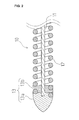
FIG. 3 is an explanatory view of a structure of a distal part of a guidewire according to a second embodiment of the present invention. -
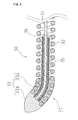
FIG. 4 is an explanatory view of a structure of a distal part of a guidewire according to a third embodiment of the present invention. - For the purpose of clearly describing the content of the present invention, various embodiments of a guidewire of the present invention will be explained below.
-
FIG. 1 is an explanatory view of a configuration of aguidewire 10 according to a first embodiment of the present invention. Theguidewire 10 includes acore shaft 11 and anouter coil 12 surrounding an outer periphery of thecore shaft 11. Thecore shaft 11 and theouter coil 12 are joined to each other with a brazing material. In the first embodiment, a distal end of thecore shaft 11 and a distal end of theouter coil 12 are connected to each other with a distal-end brazingmember 13, and a middle part of thecore shaft 11 and a proximal end of theouter coil 12 are connected to each other with a proximal-end brazingmember 14. -
FIG. 2 is an explanatory view of a structure of a distal part of theguidewire 10 according to the first embodiment of the present invention. As shown in the figure, in theguidewire 10 of this embodiment, the distal-end brazingmember 13 for joining the distal end of thecore shaft 11 and the distal end of theouter coil 12 consists of two portions. The distal-end brazingmember 13 consists of a first brazing member 13a located at a distal-most end of theguidewire 10 and a second brazingmember 13b located adjacent to and on a proximal side of the first brazing member 13a. - In the
guidewire 10, the distal end of thecore shaft 11 and the distal end of theouter coil 12 are brazed to each other first, and then, after the brazing material solidifies, the brazing member is processed so as to form the first brazing member 13a that is pointed toward the distal side (an arrowhead-like shape). Subsequently, a brazing material is applied to an area being adjacent to and on the proximal side of the first brazing member 13a to form the second brazingmember 13b. - In the
guidewire 10, a melting point of a brazing material A forming the first brazing member 13a is higher than a melting point of a brazing material B forming the second brazingmember 13b. Examples of combinations of the brazing material A and the brazing material B include the following combinations. -
- Brazing material A: a brazing material containing gold, silver and tin, and
- Brazing material B: a gold-tin brazing material
-
- Brazing material A: a brazing material containing gold, silver and tin, and
- Brazing material B: a silver-tin brazing material
-
- Brazing material A: a gold-tin brazing material, and
- Brazing material B: a silver-tin brazing material
- In the
guidewire 10 of this embodiment, the brazing material A used for forming the first brazing member 13a is a brazing material containing gold, silver and tin, and the brazing material B used for forming thesecond brazing member 13b is a gold-tin brazing material. - In the
guidewire 10, because the melting point of the first brazing member 13a is higher than the melting point of thesecond brazing member 13b adjacent to the first brazing member 13a, deformation of the first brazing member 13a due to the heat produced during formation of thesecond brazing member 13b is prevented. - Performance of the guidewire (passability in a lesion, for example) is influenced significantly by the shape of the distal-most end portion of the
guidewire 10. In this regard, theguidewire 10 is excellent in that the first brazing member 13a that has significant effect on the performance of theguidewire 10 retains its desired shape reliably even when the distal-end brazing member 13 is formed to include different parts, namely as the first brazing member 13a and thesecond brazing member 13b, for reasons related to procedures in assembling, for example. - In addition, in the
guidewire 10, the brazing material A used for forming the first brazing member 13a is the brazing material containing gold, silver and tin. The brazing material containing gold, silver and tin has a melting point (about 400°C) higher than the melting point of a gold-tin brazing material or a silver-tin brazing material (200 to 300°C) that is commonly used in a guidewire. Therefore, by forming the first brazing member 13a with the brazing material containing gold, silver and tin, deformation of the first brazing member 13a due to the heat produced during formation of thesecond brazing member 13b is prevented more reliably. -
FIG. 3 is an explanatory view of a structure of a distal part of aguidewire 20 according to a second embodiment of the present invention. Theguidewire 20 of the second embodiment is different from theguidewire 10 of the first embodiment in following respects. Theguidewire 20 of the second embodiment includes aninner coil 25 between anouter coil 22 and acore shaft 21. Theinner coil 25 is provided within theouter coil 22 and surrounds the outer periphery of thecore shaft 21. Theinner coil 25 in theguidewire 20 of this embodiment has no gap between its turns (a so-called closely wound coil). The closely woundinner coil 25 includes a closely wound single-wire coil, a closely wound coil formed by winding a plurality of single-strand wires in a helical fashion, or the like. - As shown in
FIG. 3 , asecond brazing member 23b' of a distal-end brazing member 23 does not reach thecore shaft 21. In other words, thesecond brazing member 23b is provided between theouter coil 22 and theinner coil 25 but not provided between theinner coil 25 and thecore shaft 21. - As for other points, the
guidewire 20 of the second embodiment is the same as theguidewire 10 of the first embodiment. Therefore, a brazing material for forming afirst brazing member 23a has a melting point higher than a melting point of a brazing material for forming thesecond brazing member 23b. Examples of combinations of a brazing material C forming thefirst brazing member 23a and a brazing material D forming thesecond brazing member 23b are the same as the various combinations explained above for theguidewire 10 of the first embodiment. - A proximal end of the
inner coil 25 and thecore shaft 21 are joined to each other with amiddle brazing member 26. - Also in the
guidewire 20, because the melting point of thefirst brazing member 23a is higher than the melting point of thesecond brazing member 23b, thefirst brazing member 23a at the distal-most end retains its desired shape reliably even when thefirst brazing member 23a and thesecond brazing member 23b are formed, for example, for reasons related to procedures in assembling theguidewire 20. - In addition, in the
guidewire 20, thesecond brazing member 23b is thus provided between theouter coil 22 and theinner coil 25 but not provided between theinner coil 25 and thecore shaft 21, and, as a result, the amount of the brazing material used for forming thesecond brazing member 23b is reduced. For this reason, along with the relationship that the melting point of thefirst brazing member 23a is higher than the melting point of thesecond brazing member 23b, deformation of thefirst brazing member 23a due to a heat produced during formation of thesecond brazing member 23b is prevented more reliably. -
FIG. 4 is an explanatory view of the structure of a distal part of aguidewire 30 according to a third embodiment of the present invention. Theguidewire 30 of the third embodiment is different from theguidewire 20 of the second embodiment in following respects. The distal part of theguidewire 30 includes acurved part 37. In addition, asecond brazing member 33b of a distal-end brazing member 33 is provided in thecurved part 37. - As for other points, the
guidewire 30 of the third embodiment is the same as theguidewire 20 of the second embodiment. Theguidewire 30 includes acore shaft 31, and anouter coil 32 and aninner coil 35 that surround an outer periphery of thecore shaft 31. A brazing. material forming afirst brazing member 33a of the distal-end brazing member 33 has a melting point higher than a melting point of a brazing material forming thesecond brazing member 33b. Examples of combinations of a brazing material E forming thefirst brazing member 33a and a brazing material F forming thesecond brazing member 33b are the same as the various combinations explained above for theguidewire 10 of the first embodiment. - The proximal end of the
inner coil 35 and thecore shaft 31 are joined to each other with amiddle brazing member 36. - In the third embodiment, as in the case of the
guidewire 20 of the second embodiment, thesecond brazing member 33b is provided between theouter coil 32 and theinner coil 35 but not provided between theinner coil 35 and the core shaft 31 (seeFIG. 4 ). Instead, another configuration, in which noinner coil 35 is provided and thesecond brazing member 33b is provided between theouter coil 32 and thecore shaft 31 in thecurved part 37, may also be adopted (not shown in FIGS.). - However, providing the
second brazing member 33b between theouter coil 32 and theinner coil 35 in thecurved part 37 as in this embodiment is preferable, because the amount of the brazing material used for forming thesecond brazing member 33b is reduced, and an heat influence on thefirst brazing member 33a is reduced as a result. - In the
guidewire 30, the presence of thesecond brazing member 33b in thecurved part 37 enables retention of the curved shape of theguidewire 30. - In addition, even though the
second brazing member 33b is provided in order to retain the curved shape of theguidewire 30, thefirst brazing member 33a still retains its desired shape because the melting point of the brazing material forming thefirst brazing member 33a is higher than the melting point of the brazing material forming thesecond brazing member 33b. - Thus, the
guidewire 30 of this embodiment simultaneously retains the desired curved shape of theguidewire 30 and the desired shape of thefirst brazing member 33a at the distal-most end. - Although the guidewires of various embodiments are explained above, the present invention is not limited to these embodiments and is implemented in various aspects in the scope that the gist of the present invention is not impaired. For example, the
inner coil 25 of theguidewire 20 according to the second embodiment, which is described as a closely wound coil, may be a loosely wound coil instead (a coil having turns not in contact with each other and having gaps between the turns). - However, when the
inner coil 25 is a closely wound coil, penetration of the brazing material into the space between theinner coil 25 and thecore shaft 21 is effectively prevented in a process of forming thesecond brazing member 23, and the amount of the brazing material used for forming thesecond brazing member 23b is reduced. Therefore, with consideration given to the heat influence on thefirst brazing member 23a at the time of forming thesecond brazing member 23b, theinner coil 25 is preferably the closely wound coil. -
- 10, 20, 30: Guidewire
- 11, 21, 31: Core shaft
- 12, 22, 32: Outer coil
- 13, 23, 33: Distal-end brazing member
- 13a, 23a, 33a: First brazing member
- 13b, 23b, 33b: Second brazing member
- 14: Proximal-end brazing member
- 25, 35: Inner coil
- 26, 36: Middle brazing member
- 37: Curved part
Claims (4)
- A guidewire (10, 20, 30) comprising:a core shaft (11, 21, 31),an outer coil (12, 22, 32) surrounding an outer periphery of the core shaft,a first brazing member (13a, 23a, 33a) for joining a distal end of the core shaft and a distal end of the outer coil, anda second brazing member (13b, 23b, 33b) being provided adjacent to and on a proximal side of the first brazing member, characterized in that,the melting point of the first brazing member (13a, 23a, 33a) is higher than the melting point of the second brazing member (13b, 23b, 33b).
- The guidewire (20, 30) according to claim 1, wherein
an inner coil (25, 35) is further provided between the outer coil (22, 32) and the core shaft (21, 31), and
the second brazing member (23b, 33b) is provided between the outer coil (22, 32) and the inner coil (25, 35) but not provided between the inner coil (25, 35) and the core shaft (21, 31). - The guidewire (10, 20, 30) according to claim 1 or 2, wherein
the first brazing member (13a, 23a, 33a) is formed of a brazing material containing gold, silver and tin. - The guidewire (30) according to any one of claims 1 to 3, wherein
a curved part (37) is formed at a distal part of the guidewire, and
the second brazing member (33b) is provided in the curved part (37).
Applications Claiming Priority (1)
| Application Number | Priority Date | Filing Date | Title |
|---|---|---|---|
| JP2014187257A JP6245760B2 (en) | 2014-09-16 | 2014-09-16 | Guide wire |
Publications (2)
| Publication Number | Publication Date |
|---|---|
| EP2997993A1 true EP2997993A1 (en) | 2016-03-23 |
| EP2997993B1 EP2997993B1 (en) | 2017-04-12 |
Family
ID=53397933
Family Applications (1)
| Application Number | Title | Priority Date | Filing Date |
|---|---|---|---|
| EP15172028.1A Active EP2997993B1 (en) | 2014-09-16 | 2015-06-15 | Guidewire |
Country Status (4)
| Country | Link |
|---|---|
| US (2) | US20160074630A1 (en) |
| EP (1) | EP2997993B1 (en) |
| JP (1) | JP6245760B2 (en) |
| CN (1) | CN105413040B (en) |
Families Citing this family (7)
| Publication number | Priority date | Publication date | Assignee | Title |
|---|---|---|---|---|
| WO2017221425A1 (en) * | 2016-06-24 | 2017-12-28 | 朝日インテック株式会社 | Guide wire |
| JP6917456B2 (en) * | 2017-07-19 | 2021-08-11 | 朝日インテック株式会社 | Guide wire |
| KR20250043577A (en) | 2018-04-30 | 2025-03-28 | 엑스케이스 인코포레이티드 | Introduction device and method including an electroactive tip on a guidewire |
| JP7262557B2 (en) * | 2018-05-01 | 2023-04-21 | 朝日インテック株式会社 | guide wire |
| CN112135655B (en) * | 2018-05-01 | 2023-06-13 | 朝日英达科株式会社 | guide wire |
| US20210128872A1 (en) * | 2019-10-31 | 2021-05-06 | Abbott Cardiovascular Systems Inc. | Guidewire coils with different cross section shapes |
| US11911051B2 (en) * | 2019-10-31 | 2024-02-27 | Abbott Cardiovascular Systems Inc. | Dimpled joint for guidewire |
Citations (5)
| Publication number | Priority date | Publication date | Assignee | Title |
|---|---|---|---|---|
| WO1998042399A1 (en) * | 1997-03-25 | 1998-10-01 | Radius Medical Technologies, Inc. | Flexible guidewire with radiopaque plastic tip |
| EP2481440A1 (en) * | 2011-01-28 | 2012-08-01 | Asahi Intecc Co., Ltd. | Guidewire |
| EP2532382A1 (en) * | 2011-06-06 | 2012-12-12 | Asahi Intecc Co., Ltd. | Guidewire |
| JP2013085854A (en) * | 2011-10-21 | 2013-05-13 | Asahi Intecc Co Ltd | Guide wire |
| JP2014136047A (en) | 2013-01-17 | 2014-07-28 | Japan Lifeline Co Ltd | Medical guide wire |
Family Cites Families (23)
| Publication number | Priority date | Publication date | Assignee | Title |
|---|---|---|---|---|
| US3625200A (en) * | 1969-08-26 | 1971-12-07 | Us Catheter & Instr Corp | Controlled curvable tip member |
| US4721117A (en) * | 1986-04-25 | 1988-01-26 | Advanced Cardiovascular Systems, Inc. | Torsionally stabilized guide wire with outer jacket |
| US4940062A (en) * | 1988-05-26 | 1990-07-10 | Advanced Cardiovascular Systems, Inc. | Guiding member with deflectable tip |
| US5144959A (en) * | 1989-08-15 | 1992-09-08 | C. R. Bard, Inc. | Catheter guidewire with varying radiopacity |
| US5345945A (en) * | 1990-08-29 | 1994-09-13 | Baxter International Inc. | Dual coil guidewire with radiopaque distal tip |
| US5228453A (en) * | 1991-05-07 | 1993-07-20 | Target Therapeutics, Inc. | Catheter guide wire |
| US5776080A (en) * | 1992-08-12 | 1998-07-07 | Scimed Life Systems, Inc. | Shaft movement control apparatus |
| DK175166B1 (en) * | 1995-01-03 | 2004-06-21 | Cook William Europ | Method of manufacturing an assembly for placing an embolization coil in the vascular system and such assembly as well as an apparatus for advancing the assembly |
| US5916166A (en) * | 1996-11-19 | 1999-06-29 | Interventional Technologies, Inc. | Medical guidewire with fully hardened core |
| ATE312640T1 (en) * | 2001-10-05 | 2005-12-15 | Boston Scient Ltd | COMPOSITE GUIDE WIRE |
| US7182735B2 (en) * | 2003-02-26 | 2007-02-27 | Scimed Life Systems, Inc. | Elongated intracorporal medical device |
| US20090036832A1 (en) * | 2007-08-03 | 2009-02-05 | Boston Scientific Scimed, Inc. | Guidewires and methods for manufacturing guidewires |
| US9034007B2 (en) * | 2007-09-21 | 2015-05-19 | Insera Therapeutics, Inc. | Distal embolic protection devices with a variable thickness microguidewire and methods for their use |
| JP2009190055A (en) * | 2008-02-14 | 2009-08-27 | Seiko Epson Corp | Brazing material, electronic device and method for sealing electronic device |
| JP5004256B2 (en) * | 2009-12-25 | 2012-08-22 | 朝日インテック株式会社 | Medical guidewire |
| JP5273820B2 (en) * | 2010-08-10 | 2013-08-28 | 朝日インテック株式会社 | Guide wire |
| JP5424499B2 (en) * | 2011-04-18 | 2014-02-26 | 朝日インテック株式会社 | Medical guidewire |
| JP2013094343A (en) * | 2011-10-31 | 2013-05-20 | Asahi Intecc Co Ltd | Guide wire |
| JP2013111320A (en) * | 2011-11-30 | 2013-06-10 | Asahi Intecc Co Ltd | Guide wire |
| WO2013118105A1 (en) * | 2012-02-12 | 2013-08-15 | CardioSert Ltd. | Guide wire for use with cardiovascular lesions |
| JP2013208351A (en) | 2012-03-30 | 2013-10-10 | Asahi Intecc Co Ltd | Guide wire |
| JP5783635B2 (en) * | 2012-04-26 | 2015-09-24 | 朝日インテック株式会社 | Guide wire |
| JP5709224B2 (en) * | 2013-11-25 | 2015-04-30 | 朝日インテック株式会社 | Medical guidewire |
-
2014
- 2014-09-16 JP JP2014187257A patent/JP6245760B2/en active Active
-
2015
- 2015-06-15 EP EP15172028.1A patent/EP2997993B1/en active Active
- 2015-06-15 US US14/739,349 patent/US20160074630A1/en not_active Abandoned
- 2015-06-19 CN CN201510347706.XA patent/CN105413040B/en active Active
-
2018
- 2018-01-12 US US15/870,018 patent/US11247027B2/en active Active
Patent Citations (5)
| Publication number | Priority date | Publication date | Assignee | Title |
|---|---|---|---|---|
| WO1998042399A1 (en) * | 1997-03-25 | 1998-10-01 | Radius Medical Technologies, Inc. | Flexible guidewire with radiopaque plastic tip |
| EP2481440A1 (en) * | 2011-01-28 | 2012-08-01 | Asahi Intecc Co., Ltd. | Guidewire |
| EP2532382A1 (en) * | 2011-06-06 | 2012-12-12 | Asahi Intecc Co., Ltd. | Guidewire |
| JP2013085854A (en) * | 2011-10-21 | 2013-05-13 | Asahi Intecc Co Ltd | Guide wire |
| JP2014136047A (en) | 2013-01-17 | 2014-07-28 | Japan Lifeline Co Ltd | Medical guide wire |
Also Published As
| Publication number | Publication date |
|---|---|
| US11247027B2 (en) | 2022-02-15 |
| CN105413040A (en) | 2016-03-23 |
| US20160074630A1 (en) | 2016-03-17 |
| CN105413040B (en) | 2019-05-03 |
| US20180133439A1 (en) | 2018-05-17 |
| JP2016059438A (en) | 2016-04-25 |
| JP6245760B2 (en) | 2017-12-13 |
| EP2997993B1 (en) | 2017-04-12 |
Similar Documents
| Publication | Publication Date | Title |
|---|---|---|
| EP2997993B1 (en) | Guidewire | |
| EP2689795B1 (en) | Guidewire | |
| EP2962718B1 (en) | Guidewire | |
| EP2749314B1 (en) | Guidewire | |
| EP2338556A2 (en) | Guidewire | |
| EP3072549A1 (en) | Catheter | |
| JP5240948B2 (en) | Guide wire | |
| EP2921195A1 (en) | Guide wire | |
| US10493245B2 (en) | Guide wire | |
| US20230090889A1 (en) | Guide wire | |
| US11432808B2 (en) | Guide wire | |
| US20150265809A1 (en) | Guide wire | |
| JP6624600B2 (en) | catheter | |
| JP2014161705A (en) | Guide wire | |
| EP2799106A1 (en) | Guidewire | |
| JP5733794B2 (en) | Medical guidewire | |
| EP3006075B1 (en) | Guidewire | |
| JP6368012B2 (en) | Guide wire | |
| JP6813243B2 (en) | Guide wire | |
| JP6534606B2 (en) | Guide wire | |
| JP2015077159A (en) | Guide wire | |
| EP3747498A1 (en) | Guide wire |
Legal Events
| Date | Code | Title | Description |
|---|---|---|---|
| PUAI | Public reference made under article 153(3) epc to a published international application that has entered the european phase |
Free format text: ORIGINAL CODE: 0009012 |
|
| AK | Designated contracting states |
Kind code of ref document: A1 Designated state(s): AL AT BE BG CH CY CZ DE DK EE ES FI FR GB GR HR HU IE IS IT LI LT LU LV MC MK MT NL NO PL PT RO RS SE SI SK SM TR |
|
| AX | Request for extension of the european patent |
Extension state: BA ME |
|
| 17P | Request for examination filed |
Effective date: 20160406 |
|
| RBV | Designated contracting states (corrected) |
Designated state(s): AL AT BE BG CH CY CZ DE DK EE ES FI FR GB GR HR HU IE IS IT LI LT LU LV MC MK MT NL NO PL PT RO RS SE SI SK SM TR |
|
| GRAP | Despatch of communication of intention to grant a patent |
Free format text: ORIGINAL CODE: EPIDOSNIGR1 |
|
| INTG | Intention to grant announced |
Effective date: 20161026 |
|
| GRAS | Grant fee paid |
Free format text: ORIGINAL CODE: EPIDOSNIGR3 |
|
| GRAA | (expected) grant |
Free format text: ORIGINAL CODE: 0009210 |
|
| AK | Designated contracting states |
Kind code of ref document: B1 Designated state(s): AL AT BE BG CH CY CZ DE DK EE ES FI FR GB GR HR HU IE IS IT LI LT LU LV MC MK MT NL NO PL PT RO RS SE SI SK SM TR |
|
| REG | Reference to a national code |
Ref country code: GB Ref legal event code: FG4D |
|
| REG | Reference to a national code |
Ref country code: CH Ref legal event code: EP |
|
| REG | Reference to a national code |
Ref country code: IE Ref legal event code: FG4D |
|
| REG | Reference to a national code |
Ref country code: AT Ref legal event code: REF Ref document number: 883250 Country of ref document: AT Kind code of ref document: T Effective date: 20170515 |
|
| REG | Reference to a national code |
Ref country code: DE Ref legal event code: R096 Ref document number: 602015002196 Country of ref document: DE |
|
| REG | Reference to a national code |
Ref country code: NL Ref legal event code: MP Effective date: 20170412 |
|
| REG | Reference to a national code |
Ref country code: LT Ref legal event code: MG4D |
|
| REG | Reference to a national code |
Ref country code: AT Ref legal event code: MK05 Ref document number: 883250 Country of ref document: AT Kind code of ref document: T Effective date: 20170412 |
|
| PG25 | Lapsed in a contracting state [announced via postgrant information from national office to epo] |
Ref country code: NL Free format text: LAPSE BECAUSE OF FAILURE TO SUBMIT A TRANSLATION OF THE DESCRIPTION OR TO PAY THE FEE WITHIN THE PRESCRIBED TIME-LIMIT Effective date: 20170412 |
|
| PG25 | Lapsed in a contracting state [announced via postgrant information from national office to epo] |
Ref country code: LT Free format text: LAPSE BECAUSE OF FAILURE TO SUBMIT A TRANSLATION OF THE DESCRIPTION OR TO PAY THE FEE WITHIN THE PRESCRIBED TIME-LIMIT Effective date: 20170412 Ref country code: NO Free format text: LAPSE BECAUSE OF FAILURE TO SUBMIT A TRANSLATION OF THE DESCRIPTION OR TO PAY THE FEE WITHIN THE PRESCRIBED TIME-LIMIT Effective date: 20170712 Ref country code: GR Free format text: LAPSE BECAUSE OF FAILURE TO SUBMIT A TRANSLATION OF THE DESCRIPTION OR TO PAY THE FEE WITHIN THE PRESCRIBED TIME-LIMIT Effective date: 20170713 Ref country code: HR Free format text: LAPSE BECAUSE OF FAILURE TO SUBMIT A TRANSLATION OF THE DESCRIPTION OR TO PAY THE FEE WITHIN THE PRESCRIBED TIME-LIMIT Effective date: 20170412 Ref country code: AT Free format text: LAPSE BECAUSE OF FAILURE TO SUBMIT A TRANSLATION OF THE DESCRIPTION OR TO PAY THE FEE WITHIN THE PRESCRIBED TIME-LIMIT Effective date: 20170412 Ref country code: FI Free format text: LAPSE BECAUSE OF FAILURE TO SUBMIT A TRANSLATION OF THE DESCRIPTION OR TO PAY THE FEE WITHIN THE PRESCRIBED TIME-LIMIT Effective date: 20170412 Ref country code: ES Free format text: LAPSE BECAUSE OF FAILURE TO SUBMIT A TRANSLATION OF THE DESCRIPTION OR TO PAY THE FEE WITHIN THE PRESCRIBED TIME-LIMIT Effective date: 20170412 |
|
| PG25 | Lapsed in a contracting state [announced via postgrant information from national office to epo] |
Ref country code: SE Free format text: LAPSE BECAUSE OF FAILURE TO SUBMIT A TRANSLATION OF THE DESCRIPTION OR TO PAY THE FEE WITHIN THE PRESCRIBED TIME-LIMIT Effective date: 20170412 Ref country code: RS Free format text: LAPSE BECAUSE OF FAILURE TO SUBMIT A TRANSLATION OF THE DESCRIPTION OR TO PAY THE FEE WITHIN THE PRESCRIBED TIME-LIMIT Effective date: 20170412 Ref country code: LV Free format text: LAPSE BECAUSE OF FAILURE TO SUBMIT A TRANSLATION OF THE DESCRIPTION OR TO PAY THE FEE WITHIN THE PRESCRIBED TIME-LIMIT Effective date: 20170412 Ref country code: BG Free format text: LAPSE BECAUSE OF FAILURE TO SUBMIT A TRANSLATION OF THE DESCRIPTION OR TO PAY THE FEE WITHIN THE PRESCRIBED TIME-LIMIT Effective date: 20170712 Ref country code: IS Free format text: LAPSE BECAUSE OF FAILURE TO SUBMIT A TRANSLATION OF THE DESCRIPTION OR TO PAY THE FEE WITHIN THE PRESCRIBED TIME-LIMIT Effective date: 20170812 Ref country code: PL Free format text: LAPSE BECAUSE OF FAILURE TO SUBMIT A TRANSLATION OF THE DESCRIPTION OR TO PAY THE FEE WITHIN THE PRESCRIBED TIME-LIMIT Effective date: 20170412 |
|
| REG | Reference to a national code |
Ref country code: DE Ref legal event code: R097 Ref document number: 602015002196 Country of ref document: DE |
|
| PG25 | Lapsed in a contracting state [announced via postgrant information from national office to epo] |
Ref country code: EE Free format text: LAPSE BECAUSE OF FAILURE TO SUBMIT A TRANSLATION OF THE DESCRIPTION OR TO PAY THE FEE WITHIN THE PRESCRIBED TIME-LIMIT Effective date: 20170412 Ref country code: MC Free format text: LAPSE BECAUSE OF FAILURE TO SUBMIT A TRANSLATION OF THE DESCRIPTION OR TO PAY THE FEE WITHIN THE PRESCRIBED TIME-LIMIT Effective date: 20170412 Ref country code: SK Free format text: LAPSE BECAUSE OF FAILURE TO SUBMIT A TRANSLATION OF THE DESCRIPTION OR TO PAY THE FEE WITHIN THE PRESCRIBED TIME-LIMIT Effective date: 20170412 Ref country code: DK Free format text: LAPSE BECAUSE OF FAILURE TO SUBMIT A TRANSLATION OF THE DESCRIPTION OR TO PAY THE FEE WITHIN THE PRESCRIBED TIME-LIMIT Effective date: 20170412 Ref country code: CZ Free format text: LAPSE BECAUSE OF FAILURE TO SUBMIT A TRANSLATION OF THE DESCRIPTION OR TO PAY THE FEE WITHIN THE PRESCRIBED TIME-LIMIT Effective date: 20170412 Ref country code: RO Free format text: LAPSE BECAUSE OF FAILURE TO SUBMIT A TRANSLATION OF THE DESCRIPTION OR TO PAY THE FEE WITHIN THE PRESCRIBED TIME-LIMIT Effective date: 20170412 |
|
| PLBE | No opposition filed within time limit |
Free format text: ORIGINAL CODE: 0009261 |
|
| STAA | Information on the status of an ep patent application or granted ep patent |
Free format text: STATUS: NO OPPOSITION FILED WITHIN TIME LIMIT |
|
| PG25 | Lapsed in a contracting state [announced via postgrant information from national office to epo] |
Ref country code: SM Free format text: LAPSE BECAUSE OF FAILURE TO SUBMIT A TRANSLATION OF THE DESCRIPTION OR TO PAY THE FEE WITHIN THE PRESCRIBED TIME-LIMIT Effective date: 20170412 Ref country code: IT Free format text: LAPSE BECAUSE OF FAILURE TO SUBMIT A TRANSLATION OF THE DESCRIPTION OR TO PAY THE FEE WITHIN THE PRESCRIBED TIME-LIMIT Effective date: 20170412 |
|
| 26N | No opposition filed |
Effective date: 20180115 |
|
| REG | Reference to a national code |
Ref country code: IE Ref legal event code: MM4A |
|
| REG | Reference to a national code |
Ref country code: FR Ref legal event code: ST Effective date: 20180228 |
|
| PG25 | Lapsed in a contracting state [announced via postgrant information from national office to epo] |
Ref country code: IE Free format text: LAPSE BECAUSE OF NON-PAYMENT OF DUE FEES Effective date: 20170615 Ref country code: LU Free format text: LAPSE BECAUSE OF NON-PAYMENT OF DUE FEES Effective date: 20170615 |
|
| REG | Reference to a national code |
Ref country code: BE Ref legal event code: MM Effective date: 20170630 |
|
| PG25 | Lapsed in a contracting state [announced via postgrant information from national office to epo] |
Ref country code: SI Free format text: LAPSE BECAUSE OF FAILURE TO SUBMIT A TRANSLATION OF THE DESCRIPTION OR TO PAY THE FEE WITHIN THE PRESCRIBED TIME-LIMIT Effective date: 20170412 Ref country code: FR Free format text: LAPSE BECAUSE OF NON-PAYMENT OF DUE FEES Effective date: 20170630 |
|
| PG25 | Lapsed in a contracting state [announced via postgrant information from national office to epo] |
Ref country code: BE Free format text: LAPSE BECAUSE OF NON-PAYMENT OF DUE FEES Effective date: 20170630 |
|
| PG25 | Lapsed in a contracting state [announced via postgrant information from national office to epo] |
Ref country code: MT Free format text: LAPSE BECAUSE OF NON-PAYMENT OF DUE FEES Effective date: 20170615 |
|
| REG | Reference to a national code |
Ref country code: CH Ref legal event code: PL |
|
| PG25 | Lapsed in a contracting state [announced via postgrant information from national office to epo] |
Ref country code: LI Free format text: LAPSE BECAUSE OF NON-PAYMENT OF DUE FEES Effective date: 20180630 Ref country code: CH Free format text: LAPSE BECAUSE OF NON-PAYMENT OF DUE FEES Effective date: 20180630 |
|
| PG25 | Lapsed in a contracting state [announced via postgrant information from national office to epo] |
Ref country code: HU Free format text: LAPSE BECAUSE OF FAILURE TO SUBMIT A TRANSLATION OF THE DESCRIPTION OR TO PAY THE FEE WITHIN THE PRESCRIBED TIME-LIMIT; INVALID AB INITIO Effective date: 20150615 |
|
| PG25 | Lapsed in a contracting state [announced via postgrant information from national office to epo] |
Ref country code: CY Free format text: LAPSE BECAUSE OF FAILURE TO SUBMIT A TRANSLATION OF THE DESCRIPTION OR TO PAY THE FEE WITHIN THE PRESCRIBED TIME-LIMIT Effective date: 20170412 |
|
| PG25 | Lapsed in a contracting state [announced via postgrant information from national office to epo] |
Ref country code: MK Free format text: LAPSE BECAUSE OF FAILURE TO SUBMIT A TRANSLATION OF THE DESCRIPTION OR TO PAY THE FEE WITHIN THE PRESCRIBED TIME-LIMIT Effective date: 20170412 |
|
| PG25 | Lapsed in a contracting state [announced via postgrant information from national office to epo] |
Ref country code: TR Free format text: LAPSE BECAUSE OF FAILURE TO SUBMIT A TRANSLATION OF THE DESCRIPTION OR TO PAY THE FEE WITHIN THE PRESCRIBED TIME-LIMIT Effective date: 20170412 |
|
| PG25 | Lapsed in a contracting state [announced via postgrant information from national office to epo] |
Ref country code: PT Free format text: LAPSE BECAUSE OF FAILURE TO SUBMIT A TRANSLATION OF THE DESCRIPTION OR TO PAY THE FEE WITHIN THE PRESCRIBED TIME-LIMIT Effective date: 20170412 |
|
| PG25 | Lapsed in a contracting state [announced via postgrant information from national office to epo] |
Ref country code: AL Free format text: LAPSE BECAUSE OF FAILURE TO SUBMIT A TRANSLATION OF THE DESCRIPTION OR TO PAY THE FEE WITHIN THE PRESCRIBED TIME-LIMIT Effective date: 20170412 |
|
| PGFP | Annual fee paid to national office [announced via postgrant information from national office to epo] |
Ref country code: DE Payment date: 20250618 Year of fee payment: 11 |
|
| PGFP | Annual fee paid to national office [announced via postgrant information from national office to epo] |
Ref country code: GB Payment date: 20250618 Year of fee payment: 11 |