EP2996813B1 - Bewässerungssystem mit veränderlicher geschwindigkeit und verlängerungsarm - Google Patents
Bewässerungssystem mit veränderlicher geschwindigkeit und verlängerungsarm Download PDFInfo
- Publication number
- EP2996813B1 EP2996813B1 EP14791248.9A EP14791248A EP2996813B1 EP 2996813 B1 EP2996813 B1 EP 2996813B1 EP 14791248 A EP14791248 A EP 14791248A EP 2996813 B1 EP2996813 B1 EP 2996813B1
- Authority
- EP
- European Patent Office
- Prior art keywords
- extension arm
- variable
- irrigation system
- tower
- main section
- Prior art date
- Legal status (The legal status is an assumption and is not a legal conclusion. Google has not performed a legal analysis and makes no representation as to the accuracy of the status listed.)
- Active
Links
Images


Classifications
-
- A—HUMAN NECESSITIES
- A01—AGRICULTURE; FORESTRY; ANIMAL HUSBANDRY; HUNTING; TRAPPING; FISHING
- A01G—HORTICULTURE; CULTIVATION OF VEGETABLES, FLOWERS, RICE, FRUIT, VINES, HOPS OR SEAWEED; FORESTRY; WATERING
- A01G25/00—Watering gardens, fields, sports grounds or the like
- A01G25/09—Watering arrangements making use of movable installations on wheels or the like
- A01G25/092—Watering arrangements making use of movable installations on wheels or the like movable around a pivot centre
-
- B—PERFORMING OPERATIONS; TRANSPORTING
- B05—SPRAYING OR ATOMISING IN GENERAL; APPLYING FLUENT MATERIALS TO SURFACES, IN GENERAL
- B05B—SPRAYING APPARATUS; ATOMISING APPARATUS; NOZZLES
- B05B1/00—Nozzles, spray heads or other outlets, with or without auxiliary devices such as valves, heating means
- B05B1/14—Nozzles, spray heads or other outlets, with or without auxiliary devices such as valves, heating means with multiple outlet openings; with strainers in or outside the outlet opening
- B05B1/20—Perforated pipes or troughs, e.g. spray booms; Outlet elements therefor
-
- B—PERFORMING OPERATIONS; TRANSPORTING
- B05—SPRAYING OR ATOMISING IN GENERAL; APPLYING FLUENT MATERIALS TO SURFACES, IN GENERAL
- B05B—SPRAYING APPARATUS; ATOMISING APPARATUS; NOZZLES
- B05B12/00—Arrangements for controlling delivery; Arrangements for controlling the spray area
- B05B12/08—Arrangements for controlling delivery; Arrangements for controlling the spray area responsive to condition of liquid or other fluent material to be discharged, of ambient medium or of target ; responsive to condition of spray devices or of supply means, e.g. pipes, pumps or their drive means
- B05B12/12—Arrangements for controlling delivery; Arrangements for controlling the spray area responsive to condition of liquid or other fluent material to be discharged, of ambient medium or of target ; responsive to condition of spray devices or of supply means, e.g. pipes, pumps or their drive means responsive to conditions of ambient medium or target, e.g. humidity, temperature position or movement of the target relative to the spray apparatus
-
- B—PERFORMING OPERATIONS; TRANSPORTING
- B05—SPRAYING OR ATOMISING IN GENERAL; APPLYING FLUENT MATERIALS TO SURFACES, IN GENERAL
- B05B—SPRAYING APPARATUS; ATOMISING APPARATUS; NOZZLES
- B05B3/00—Spraying or sprinkling apparatus with moving outlet elements or moving deflecting elements
-
- B—PERFORMING OPERATIONS; TRANSPORTING
- B05—SPRAYING OR ATOMISING IN GENERAL; APPLYING FLUENT MATERIALS TO SURFACES, IN GENERAL
- B05B—SPRAYING APPARATUS; ATOMISING APPARATUS; NOZZLES
- B05B9/00—Spraying apparatus for discharge of liquids or other fluent material, without essentially mixing with gas or vapour
- B05B9/007—At least a part of the apparatus, e.g. a container, being provided with means, e.g. wheels, for allowing its displacement relative to the ground
Definitions
- an irrigation system configured to maintain a near straight (e.g., an at least zero degree (0°)) alignment.
- an irrigation system includes multiple interconnected spans which are supported by multiple tower structures.
- Each tower structure includes a variable-speed drive unit for selectively driving a tower structure at a selected speed.
- the irrigation system also includes multiple sensors that are each associated with a corresponding span to determine an alignment of the corresponding span with respect to adjacent spans. Each of the sensors is in communication with a corresponding variable-drive control unit.
- Each of the variable-drive control units are configured to control the selected speed of a corresponding variable-speed drive unit to maintain the interconnected spans in a substantially linear orientation with respect to adjacent ones of the plurality of interconnected spans along a generally longitudinally oriented axis (e.g., maintain alignment of the spans with respect to each other)
- FIG. 1A illustrates a self-propelled (e.g., mechanized) irrigation system (assembly) 100 in accordance with example implementations of the present disclosure.
- self- propelled irrigation systems include a center pivot irrigation system, a linear move irrigation system, or the like.
- FIG. 1A illustrates an embodiment of the present disclosure where the irrigation system 100 is a center pivot irrigation system.
- the present disclosure may be implemented in other self-propelled irrigation systems (e.g., linear move irrigation systems).
- the system 100 includes a center pivot structure 102, a main section assembly 104 (irrigation section assembly, main boom assembly) coupled (e.g., connected) to the center pivot structure 102.
- the center pivot structure 102 has access to a well, a water repository (e.g., water tank), or other fluid source, to furnish water to the irrigation system 100.
- a water repository e.g., water tank
- the well may be located under the center pivot structure 102.
- the well may be in close proximity to the cultivation area 101 (e.g., field).
- the fluid source may be coupled to a repository or other source of agricultural products to inject fertilizers, pesticides, and/or other chemicals into the fluids to create an applicant for application during irrigation.
- the applicant may be water, fertilizer, herbicide, pesticide, combinations thereof, or the like.
- the irrigation system 100 may be coupled to a fluid displacement device (e.g., a pump assembly) configured to furnish applicant throughout the irrigation system 100.
- the fluid displacement device may assist in displacing fluid from the fluid source (e.g., well, water repository, etc.) to the conduit portions of the irrigation system which are described herein.
- the center pivot structure 102 can be fixed or can be towable such that an operator can move the irrigation system 100 from one field to another.
- the center pivot structure 102 may comprise a frame assembly (e.g., galvanized steel frame assembly, and so forth).
- the main section assembly 104 includes a number of interconnected spans 106, 108, 109 (e.g., irrigation spans) supported by one or more tower structures 110, 111 (intermediate tower structures) and an end tower structure 112.
- the tower structures 110, 111, 112 may be any tower configuration known in the art to adequately support the conduits (e.g., water pipe sections) described herein. It is understood that the section assembly 104 may include any number of spans and tower structures.
- the tower structures 110, 111 and the end tower structure 112 each include wheels 114, 116, to assist in traversing the irrigation system 100 (e.g., allowing the main section assembly 104 to pivot) about a cultivation area (e.g., field).
- the wheels 114, 116 may be driven by a suitable variable-drive unit 118 (e.g., drive motor), or the like, to assist in traversing the system 100 about the specified area.
- each tower structure 110 may include a drive unit 118 to propel the respective tower structure 110, 111, 112 (and the irrigation system 100) through the cultivation area.
- the drive units 118 comprise variable-speed motors that are configured to selectively drive a tower structure at a selected speed.
- the drive units 118 may comprise electric switched reluctance motors configured to drive the irrigation system 100 in a forward direction or a reverse direction.
- the alignment between each span 106, 108, 109 (e.g., machine alignment) of the irrigation system 100 is maintained by a suitable mechanical linkage at each drive unit span joint.
- the drive unit span joint is configured as a potentiometer, or other sensor, that serves to accelerate or decelerate the respective drive unit 118 (switched reluctance motors, which are described in greater detail below) to at least substantially keep the respective span 106, 108, 109 in alignment with the other irrigation spans.
- Alignment may be defined as each span 106, 108, 109 being aligned with one or more adjacent spans along a generally linear longitudinal axis (e.g., defined with respect to a generally horizontal surface, such as the ground).
- each span 106, 108 includes conduits 120, 121, 122 (e.g., pipes) that are configured to carry (e.g., transport, provide, and so forth) liquid (e.g., applicant) along the length of the system 100 to one or more applicant dispersal assemblies that are configured to irrigate the cultivation area.
- Each conduit 120, 121, 122 may be coupled to one another to allow fluid communication between each conduit.
- the conduits 120, 121, 122 may be supported by truss-type framework structures 124, 125, 126.
- the main fluid displacement device may be configured to displace applicant through the conduits 120, 121, 122. As shown in FIG.
- the irrigation system 100 also includes an extension arm 123 that is pivotally connected to the end tower 112.
- the extension arm 123 is supported by a swing tower 128 having steerable wheels 129 driven by a motor.
- the extension arm 123 is folded in relative to the end tower 112 when the arm 123 is not irrigating a comer of a field and may be pivoted outwardly away from the end tower 112 while irrigating the comers of a field.
- the extension arm 123 is coupled to the end tower 112 by an articulating pivot joint to allow the extension arm 123 to articulate or bend relative the end tower 112 or to the end of the extension arm 123.
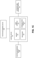
- the irrigation system 100 includes a control device 130, which is accessible via the control panel 131, that is in electronic communication with one or more components of the system 100.
- the control device 130 may be in electronic communication with one or more tower boxes mounted at one or more tower structures 110, 111, 112 and position-determining devices 133A, 133B utilized to determine the position of the irrigation system and a position of the extension arm 123, respectively.
- the position-determining devices 133A, 133B may be an angle sensor, or the like, mounted to the center pivot structure 102 and the end tower 112, respectively.
- the angle sensor 133A may be positioned between the center pivot structure 102 and the main section assembly 104 for determining the rotational position of the main section assembly 104 with respect to an axis line 135. Additionally, the control device 130 is configured to utilize the positional signals from the device 133B to determine an actual position of the extension arm 123 relative to the end tower structure 112.
- control device 130 is mounted to the central pivot structure 102 (i.e., control panel 131), or a control cart. In another example implementation, the control device 130 is located at the end tower structure 112. The control device 130 is generally located on the structural element of the irrigation system 100 where the applicant/water is introduced into the irrigation system; however, other configurations known in the art are within the scope of the present disclosure.
- the control device 130 is configured to monitor operating conditions and configured to control various functions of the irrigation system 100.
- the control device 130 actively monitors the irrigation system's 100 function and performance including, but not limited to: a position of one or more conduit sections 120, 121, 122 or tower structures 110, I11, 112 (e.g., the position of the main section assembly 104), whether the irrigation system 100 is powered on or off, a voltage parameter associated with the irrigation system 100, a motor speed parameter associated with the irrigation system 100, an approximate ground speed parameter associated with the irrigation system 100, a direction parameter associated with theirrigation system 100, a diagnostic parameter associated with the irrigation system 100, whether the applicant is being supplied to the irrigation system 100 (e.g., whether the fluid displacement device is operational), whether the Stop in Slot (SIS) is powered on or off, an applicant pressure associated with the irrigation system 100, a time parameter, a date parameter, a field position parameter of the irrigation system components, end-gun status, and whether the programs (e.g., software programs, etc.) are running properly
- the control device 130 also controls the irrigation system's 100 functions and settings including, but not limited to: start and stop, selectively powering the main fluid displacement device, an applicant application depth parameter, the direction of travel associated with the irrigation system 100, selectively powering the SIS, automatically reversing or stopping the irrigation system 100, automatically restarting the irrigation system 100, providing an operator auxiliary control to the system 100, writing and editing irrigation programs (e.g., irrigation software programs), and controlling sector and sequential programs (e.g., software programs).
- the control device 130 may cause an alert to be issued to the operator ifthere are any errors in the operation of the irrigation system 100 or if any of the functions or conditions monitored by the control device 130 have been compromised (e.g., ceased operation or are outside an acceptable range).
- switched reluctance motors 142 allow for the constant movement of the center pivot irrigation systems (as compared to center pivot irrigation systems not having switched reluctance motors), which may allow for greater uniform application of water and/or chemicals while lessening waste.
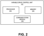
- variable-drive units 118 may each include a variable-drive control unit 143.
- the variable-drive control unit 143 includes a processor 202 that is configured to provide processing functionality to the variable-drive control unit 143.
- the processor 202 may execute one or more software programs and/or instructions described herein.
- the variable-drive control unit 143 also includes a memory 204, which is an example of tangible computer-readable media that provides storage functionality to store various data associated with the operation of the variable-drive control unit 143, such as software programs/modules and code segments mentioned herein, or other data to instruct the processor 202 to perform the steps described herein.
- variable-drive control unit 143 is directly connected with the respective sensor 144 (e.g., via a wired connection). In this implementation, the variable control unit 143 is also directly connected to the respective switched reluctance motor 142 (e.g., via a wired connection). In another implementation, the variable-drive control unit 143 may include a communication module 206, which is configured to communicate with other components (e.g., switched reluctance motors 142, sensors 144) over a communication network (e.g., a wireless network, a wired network, etc.).
- a communication network e.g., a wireless network, a wired network, etc.
- the communication module 206 may be directed coupled (e.g., via one or more wires, or the like) to a corresponding variable- drive unit 118, as well as a corresponding sensor 144.
- the communication module 206 may be representative of a variety of communication components and functionality, including, but not limited to: one or more antennas, a transmitter and/or receiver, a transceiver, or the like. While FIG. 2 illustrates that the variable-drive control unit 143 is integrated (e.g., housed within) with the variable-drive unit 118, it is understood that the variable-drive control unit 143 may be a standalone unit.
- variable-drive control unit 143 is configured to furnish (e.g., provide, generate, transmit) one or more drive unit signals to control the switched reluctance motor 142.
- the processor 202 of the variable-drive control unit 143 is configured to translate the angle information furnished by the sensor 144 into speed information that is utilized to control the switched reluctance motor 142 (e.g., control the speed of the corresponding span 106, 108, 109).
- variable-drive control unit 143 may furnish one or more drive unit signals that are configured to cause a specified drive unit 118 to modify the speed (e.g., increase the speed, decrease the speed) of the unit 118 (e.g., switched reluctance motor 142), which causes the corresponding span 106, 108, 109 to vary in speed.
- the control device 130 is configured to communicate with each variable-drive control unit during operation of the irrigation system 100.
- the variable-drive control unit 143 may be configured to furnish diagnostic and/or performance information regarding the variable-drive unit 118 to the control device 130.
- a sensor 144 is configured to continually monitor (determine) the alignment values (e.g., angles) of the corresponding spans 106, 108, 109.
- the variable-drive control unit 143 is configured to furnish a drive unit signal configured to cause the corresponding drive unit 118 to continuously modify the speed of the drive unit 118 (e.g., modify the speed of the switched reluctance motor 142) to re-align the corresponding mis-aligned span 106, 108, 109.
- variable-drive control unit 143 is configured to continuously provide signals, based upon the sensor 144 signal, to cause at least substantially near-perfect (e.g., near-horizontal alignment) between the corresponding spans by way of the switched-reluctance motors 142.
- the speed of the drive unit 118 may be varied (via one or more drive unit signals) based upon a deviation from a zero degree (0° span to span alignment).
- the irrigation system 100 e.g., sensors 144, variable-drive control unit 143, etc.
- the irrigation system 100 may utilize a proportional-integral-derivative control algorithm, or the like, to fine tune the speed of a particular drive unit 118.
- the variable-drive control unit 143 is configured to continuously furnish one or more drive unit signals to the drive units 118 when the sensor 144 determines that a particular span is mis aligned.
- drive unit (control) signals configured to adjust the set speed of a particular drive unit 118 are furnished to the particular drive unit 118, which causes a drive unit speed adjustment.
- the drive unit signals may be based on potentiometer signals, captive alignment sensor signals, laser based alignment sensor signals, non-contact proximity sensor signals, and/or other parameters useful in determining a new set speed for a particular drive unit.
- the variable-drive control unit 143 includes a processor 202 that is configured to receive and to utilize data (information) from the tower structures 110, 111, 112 in determining the set speed for a particular drive unit 118.
- the processor 202 may comprise a microcontroller that includes dedicated logic (e.g., circuitry) for controlling the variable-drive units 118 and/or the switched reluctance motors 142.
- the variable-drive control unit 143 may be in communication with each ofthe tower structures 110, 111, 112 by way of sensors 144, or the like. As described above, this may allow for finer speed control and dynamic alignment correction of the irrigation system 100.
- the irrigation system 100 includes an extension arm steering assembly includes the extension arm steering control 145 that is configured to steer the extension arm 123 to a desired position.
- the processor 136 is configured to instruct the extension arm steering control 145 to steer the extension arm 123 to a desired position.
- the irrigation system 100 is configured to maintain the spans 110, 111, 112 in a substantially linear orientation with respect to an adjacent span along a generally longitudinally oriented axis.
- the position-determining device 133A is utilized to determine an actual position of the main section assembly 104
- the position-determining device 133B is utilized to determine an actual position of the extension arm 123.
- the control device 130 is configured to determine a position of the main section assembly 104.
- An angle sensor 133B is configured to measure an angle value (8) (e.g., angular measurement) between the end tower 112 and the extension arm 123.
- control device 130 may be configured to determine an actual position of the extension tower 123 based upon the angular measurement furnished by the angle sensor 133B.
- the control device 130 is configured to determine a desired position of the extension arm 123 based upon the determined position of the main section assembly 104.
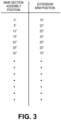
- the control device 130 may utilize a look-up table, as shown in FIG. 3 , that contains a list of desired positions of the extension arm 123 that correspond to an actual position of the main section assembly 104.
- a processor 136 is configured to access the look-up table that is stored within a respective memory 134.
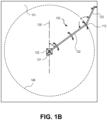
- the look- up table includes a number of positions of the main section assembly's irrigation path 146 (see FIG. IB).
- the look-up table also includes a desired position of the extension arm 123 for each of the main section assembly's position.
- the positions of the extension arm 123 are represented by an angle (8) formed between the extension arm 123 and the main section assembly 104 as shown in FIG. lB.
- the main section assembly 104 and the extension arm 123 may be represented in the look-up table in any suitable format.
- the positions may be represented as geographic coordinates, distances from other objects, angles from other objects, or the like.
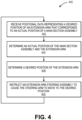
- FIG. 4 illustrates an example method 400 for re-positioning an extension arm 123 based upon a position of the main section assembly 104.
- positional data representing a desired position of an extension arm that corresponds to a position of a main section assembly is received (Block 402).
- the look-up table includes a list of desired positions of the extension arm 123 that correspond to a position of the main section assembly 104.
- the actual position of the extension arm and the main section assembly is determined (Block 404). As described above, a position of the main section assembly 104 is determined utilizing a position-determining device 133A that provides positional data representing a position of the main irrigation assembly 104 to the control device 130. Similarly, the position- determining device 133B is configured to furnish positional data representing a position of the extension arm 123 to the control device 130. Once the positions are determined, a desired position of an extension arm is determined (Block 406). In an implementation, the control device 130 configured to utilize the look-up table to determine a desired position of the extension arm 123 based upon the current position of the main section assembly 104.
- an extension arm steering assembly is instructed to cause the steering arm to move to the desired position (Block 408).
- the control device 130 is configured to, via the processor 136, instruct the extension arm steering control 145 to steer in or steer out, or move the extension arm 123 to the desired position based upon the position of the main section assembly 104.
- the processor 136 is configured to compare an actual position of the extension arm 123 to the desired position of the extension arm 123. If the actual position deviates from the desired position greater than a predetermined threshold, a processor 136 is configured to calculate a steering correction value and then instructs the extension arm to steer toward the desired position.
- the method 500 can return to Block 508 to determine the actual positions of the main section assembly 104 and the extension arm 123 and make any steering adjustments as required.
- FIG. 5 illustrates an example method 500 for determining mis-alignment of an irrigation system.
- a determination is made of whether one or more irrigation spans are mis-aligned beyond a preset maximum value (Decision Block 502).
- the sensors 144 are configured to determine whether one or more of the spans 106, 108, 109 are mis-aligned beyond a preset maximum value. If an irrigation span is mis-aligned beyond a preset maximum value (NO from Decision Block 502), a variable-drive control unit is configured to cause a switched reluctance motor to vary a speed of at least one irrigation span to re-align a mis-aligned irrigation span (Block 506). If the system cannot maintain the desired alignment (YES from Decision Block 502), the irrigation system is stopped or shut down (Block 508) to prevent further misalignment and to prevent improper steering of the extension arm 123.
Landscapes
- Engineering & Computer Science (AREA)
- Water Supply & Treatment (AREA)
- Life Sciences & Earth Sciences (AREA)
- Environmental Sciences (AREA)
- Guiding Agricultural Machines (AREA)
- Control Of Position, Course, Altitude, Or Attitude Of Moving Bodies (AREA)
- Manipulator (AREA)
Claims (5)
- Bewässerungssystem mit einer zentralen Drehachsenstruktur (102) und einer Hauptabschnitt-Baugruppe (104), die mit der zentralen Drehachsenstruktur (102) gekoppelt ist, und ferner umfassend:Die Hauptabschnitt-Baugruppe (104), die eine Vielzahl von miteinander verbundenen Bereichen (106, 108, 109) einschließt,eine Vielzahl von Maststrukturen (110, 111, 112) zum Abstützen der miteinander verbundenen Bereiche, wobei jede der Vielzahl von Maststrukturen eine Antriebseinheit mit variabler Geschwindigkeit (118) einschließt, um eine Maststruktur selektiv mit einer ausgewählten Geschwindigkeit anzutreiben, eine Vielzahl von Sensoren (144), wobei jeder der Vielzahl von Sensoren mit einem entsprechenden der Vielzahl von miteinander verbundenen Bereichen verbunden und konfiguriert ist, eine Ausrichtung eines entsprechenden der Vielzahl von miteinander verbundenen Bereichen zu bestimmen,eine Vielzahl von variablen Antriebssteuereinheiten (143), wobei jede variable Antriebssteuereinheit der Vielzahl von Antriebssteuereinheiten in Verbindung mit einer entsprechenden Antriebseinheit mit variabler Geschwindigkeit und einem entsprechenden Sensor (144) steht, jede variable Antriebssteuereinheit ist so konfiguriert, dass sie die ausgewählte Geschwindigkeit der entsprechenden Antriebseinheit mit variabler Geschwindigkeit steuert, um die Vielzahl von miteinander verbundenen Bereichen in einer im Wesentlichen linearen Ausrichtung im Verhältnis zu benachbarten der Vielzahl von miteinander verbundenen Bereichen entlang einer im Allgemeinen längs ausgerichteten Achse zu halten,ein Steuergerät (130), konfiguriert, um mit jeder variablen Antriebssteuereinheit zu kommunizieren, wobei die variablen Antriebssteuereinheiten so konfiguriert sind, dass sie, wenn eine Fehlausrichtung durch einen Sensor (144) festgestellt wird, ein Antriebseinheitsignal ausgeben, das konfiguriert ist, die entsprechende Antriebseinheit (118) zu veranlassen, die Geschwindigkeit der Antriebseinheit (118) fortlaufend zu verändern, um einen entsprechenden der Vielzahl von miteinander verbundenen Bereichen (106, 108, 109) der Hauptabschnitt-Baugruppe neu auszurichten; die Vielzahl der Maststrukturen schließt einen Endmast (112) ein;einen Auslegerarm (123), der mit dem Endmast (112) über ein bewegliches Drehgelenk gekoppelt ist, um es dem Auslegerarm (123) zu erlauben, sich im Verhältnis zum Endmast (112) zu bewegen oder zu biegen,der Auslegerarm liegt auf einem Schwingmast (128) mit steuerbaren Rädern (129), die von einem Motor angetrieben werden, der über eine Auslegerarm-Lenkwelle (145) steuerbar ist, um den Auslegerarm (123) nach innen oder außen zu steuern oder zu bewegen;eine erste Positionsbestimmungskomponente (133A), die konfiguriert ist, eine aktuelle Position der Hauptabschnitt-Baugruppe zu bestimmen;eine zweite Positionsbestimmungskomponente (133B), die konfiguriert ist, eine aktuelle Position des Auslegerarms (123) zu bestimmen;
unddas Steuergerät (130), das einen Speicher (134), einen Prozessor (136), eine Benutzerschnittstelle (138) und ein Kommunikationsmodul (140) einschließt, das kommunikativ mit der ersten Positionsbestimmungskomponente (133A) und der zweiten Positionsbestimmungskomponente (133B) gekoppelt ist, dadurch gekennzeichnet, dass das Steuergerät ferner für Folgendes konfiguriert ist:Bestimmen einer gewünschten Position des Auslegerarms (123), basierend auf der aktuellen Position der Hauptabschnitt-Baugruppe (104);Vergleichen der gewünschten Position des Auslegerarms (123) im Verhältnis zu dem Endmast (112) mit der aktuellen Position des Auslegerarms (123) im Verhältnis zu einem Endmast (112);
undüber den Prozessor, Anweisen der Auslegerarm-Lenkwelle (145), den Auslegerarm (123) in die gewünschte Position hinein oder heraus zu steuern oder zu bewegen, wobei die gewünschte Position auf der Position der Hauptabschnitt-Baugruppe (104) basiert, wenn die gewünschte Position des Auslegerarms (123) und die aktuelle Position des Auslegerarms um mehr als einen vorbestimmten Schwellenwert voneinander abweichen,und wobei die gewünschte Position einer Position des Bewässerungspfads der Hauptabschnitt-Baugruppe (146) entspricht, wobei der Auslegerarm (123) im Verhältnis zu dem Endmast (112) eingeklappt wird, wenn der Auslegerarm (123) keine Ecke des Felds bewässert und nach außen von dem Endmast (112) weggedreht wird, wenn die Ecken eines Felds bewässert werden. - Bewässerungssystem nach Anspruch 1, wobei mindestens ein Sensor (144) konfiguriert ist, einen Winkel α zwischen einem ersten entsprechenden miteinander verbundenen Bereich der Vielzahl von miteinander verbundenen Bereiche zu bestimmen und einen zweiten entsprechenden miteinander verbundenen Bereich der Vielzahl von miteinander verbundenen Bereiche zu bestimmen; wobei die entsprechende variable Antriebssteuereinheit (143) konfiguriert ist, eine ausgewählte Geschwindigkeit zu bestimmen, um die Vielzahl der miteinander verbundenen Bereiche in einer im Wesentlichen linearen Ausrichtung im Verhältnis zu benachbarten der Vielzahl von miteinander verbundenen Bereiche entlang einer im Allgemeinen längs ausgerichteten Achse zu halten, die ausgewählte Geschwindigkeit basiert dabei auf dem Winkel α.
- Bewässerungssystem nach Anspruch 1, wobei jeder Sensor der Vielzahl von Sensoren (133) in direkter Verbindung mit einer entsprechenden variablen Antriebssteuereinheit (143) der Vielzahl von variablen Antriebssteuereinheiten steht.
- Bewässerungssystem nach Anspruch 1, wobei die Antriebseinheiten (143) mit variabler Geschwindigkeit geschaltete Reluktanzmotoren (142) umfassen.
- Bewässerungssystem nach Anspruch 1, wobei die Vielzahl von Sensoren (144) mindestens eines aus einem Potentiometer, einem unverlierbaren Ausrichtungssensor, einem laserbasierten Ausrichtungssensor oder einem berührungslosen Näherungssensor umfasst.
Applications Claiming Priority (2)
| Application Number | Priority Date | Filing Date | Title |
|---|---|---|---|
| US201361818581P | 2013-05-02 | 2013-05-02 | |
| PCT/US2014/036523 WO2014179663A1 (en) | 2013-05-02 | 2014-05-02 | Variable-speed irrigation system having an extension arm |
Publications (4)
| Publication Number | Publication Date |
|---|---|
| EP2996813A1 EP2996813A1 (de) | 2016-03-23 |
| EP2996813A4 EP2996813A4 (de) | 2017-03-15 |
| EP2996813B1 true EP2996813B1 (de) | 2025-04-09 |
| EP2996813C0 EP2996813C0 (de) | 2025-04-09 |
Family
ID=51840942
Family Applications (1)
| Application Number | Title | Priority Date | Filing Date |
|---|---|---|---|
| EP14791248.9A Active EP2996813B1 (de) | 2013-05-02 | 2014-05-02 | Bewässerungssystem mit veränderlicher geschwindigkeit und verlängerungsarm |
Country Status (6)
| Country | Link |
|---|---|
| US (1) | US20140326808A1 (de) |
| EP (1) | EP2996813B1 (de) |
| AU (5) | AU2014259718A1 (de) |
| BR (1) | BR112015027554B1 (de) |
| WO (1) | WO2014179663A1 (de) |
| ZA (1) | ZA201508090B (de) |
Families Citing this family (20)
| Publication number | Priority date | Publication date | Assignee | Title |
|---|---|---|---|---|
| US8849467B2 (en) * | 2011-07-13 | 2014-09-30 | Lindsay Corporation | Control system for stopping or reversing movement of an irrigation system |
| CN106031906B (zh) * | 2015-03-16 | 2019-09-17 | 泉州台商投资区五季网络有限公司 | 一种圆形喷灌机喷药控制系统 |
| US10064349B1 (en) * | 2015-08-11 | 2018-09-04 | Wesley Allen Bainter | Apparatus for stabilizing irrigation towers |
| US11406072B1 (en) * | 2015-08-11 | 2022-08-09 | Wesley Allen Bainter | Apparatus for stabilizing irrigation towers |
| US10384557B2 (en) * | 2016-06-02 | 2019-08-20 | Irrovation LLC | Irrigation system with position-based predictive analytics |
| EP3654760B1 (de) | 2017-07-20 | 2023-08-23 | Valmont Industries, Inc. | System zur festkörper-turmsteuerung eines bewässerungssystems mit zentralem drehpunkt |
| US11251725B2 (en) | 2017-07-20 | 2022-02-15 | Valmont Industries, Inc. | Electronic braking system for an irrigation machine |
| US10939627B2 (en) * | 2018-10-11 | 2021-03-09 | Valmont Industries, Inc. | System and method for cascading alignment of independent drive systems |
| WO2020198391A1 (en) * | 2019-03-25 | 2020-10-01 | Realmfive, Inc. | Smart irrigation system |
| US11856899B2 (en) * | 2019-06-20 | 2024-01-02 | Reinke Manufacturing Co., Inc. | Monitoring and control of a movable tower in an irrigation system |
| US11357180B2 (en) | 2019-06-20 | 2022-06-14 | Reinke Manufacturing Co., Inc. | Monitoring and control of a movable tower in an irrigation system |
| US20220030785A1 (en) * | 2020-07-29 | 2022-02-03 | Lindsay Corporation | Fault notification system and method for use with an irrigation system |
| US11917954B2 (en) * | 2020-08-04 | 2024-03-05 | Lindsay Corporation | Wheel track monitoring system for an irrigation system |
| US11800840B2 (en) * | 2020-08-04 | 2023-10-31 | Lindsay Corporation | Irrigation system alignment controller |
| US12490669B1 (en) | 2020-12-01 | 2025-12-09 | Fieldbot, Llc | Method and apparatus for pumping a fluid additive into an irrigation system for field application |
| US12389844B1 (en) | 2020-12-01 | 2025-08-19 | Fieldbot, Llc | Method and apparatus for delivering an additive utilizing an irrigation system for field application |
| CA3216152A1 (en) * | 2021-05-03 | 2022-11-10 | John Kastl | Multi-corner irrigation system having multiple steerable points within mobile irrigation machine and method for implementing the same |
| US12075733B2 (en) * | 2021-10-13 | 2024-09-03 | Christopher Guy Williams | Irrigation system |
| US20230210066A1 (en) * | 2022-01-05 | 2023-07-06 | Lindsay Corporation | Modular irrigation tower |
| US12169409B2 (en) * | 2022-05-09 | 2024-12-17 | Lindsay Corporation | Auto-reverse control with network |
Family Cites Families (6)
| Publication number | Priority date | Publication date | Assignee | Title |
|---|---|---|---|---|
| US6755362B2 (en) * | 2001-10-04 | 2004-06-29 | Neal Krieger | Irrigation system with variable speed drive system |
| US6928339B2 (en) * | 2002-11-21 | 2005-08-09 | Reinke Manufacturing Company, Inc. | GPS-based control system and method for controlling mechanized irrigation systems |
| WO2013010152A2 (en) | 2011-07-14 | 2013-01-17 | Valmont Industries, Inc. | Variable-speed irrigation system |
| US8763937B2 (en) * | 2011-08-29 | 2014-07-01 | Lindsay Corporation | Methods and systems for aligning irrigation systems |
| US20130087631A1 (en) | 2011-10-05 | 2013-04-11 | Lindsay Corporation | Method and system for positioning an extension arm of a center pivot irrigation system |
| US8936208B2 (en) * | 2011-10-07 | 2015-01-20 | Lindsay Corporation | Method and system for operating irrigation systems motors |
-
2014
- 2014-05-02 EP EP14791248.9A patent/EP2996813B1/de active Active
- 2014-05-02 US US14/268,050 patent/US20140326808A1/en not_active Abandoned
- 2014-05-02 BR BR112015027554-0A patent/BR112015027554B1/pt active IP Right Grant
- 2014-05-02 WO PCT/US2014/036523 patent/WO2014179663A1/en not_active Ceased
- 2014-05-02 AU AU2014259718A patent/AU2014259718A1/en not_active Abandoned
-
2015
- 2015-11-02 ZA ZA2015/08090A patent/ZA201508090B/en unknown
-
2018
- 2018-10-04 AU AU2018241097A patent/AU2018241097A1/en not_active Abandoned
-
2020
- 2020-06-12 AU AU2020203878A patent/AU2020203878A1/en not_active Abandoned
-
2022
- 2022-05-02 AU AU2022202911A patent/AU2022202911A1/en not_active Abandoned
-
2024
- 2024-08-20 AU AU2024210995A patent/AU2024210995A1/en active Pending
Also Published As
| Publication number | Publication date |
|---|---|
| AU2024210995A1 (en) | 2024-09-05 |
| BR112015027554A2 (pt) | 2017-09-19 |
| AU2022202911A1 (en) | 2022-05-26 |
| AU2018241097A1 (en) | 2018-10-25 |
| EP2996813A4 (de) | 2017-03-15 |
| ZA201508090B (en) | 2017-08-30 |
| US20140326808A1 (en) | 2014-11-06 |
| BR112015027554B1 (pt) | 2021-03-30 |
| AU2014259718A1 (en) | 2015-11-12 |
| EP2996813A1 (de) | 2016-03-23 |
| WO2014179663A1 (en) | 2014-11-06 |
| AU2020203878A1 (en) | 2020-07-02 |
| EP2996813C0 (de) | 2025-04-09 |
Similar Documents
| Publication | Publication Date | Title |
|---|---|---|
| EP2996813B1 (de) | Bewässerungssystem mit veränderlicher geschwindigkeit und verlängerungsarm | |
| US8948979B2 (en) | Variable-speed irrigation system | |
| US9119355B2 (en) | Irrigation system having an applicant dispersal assembly | |
| US10474165B2 (en) | Method and system for operating irrigation systems motors | |
| US8763937B2 (en) | Methods and systems for aligning irrigation systems | |
| US20130008977A1 (en) | System and method for controlling operation of an irrigation system end gun | |
| US9101097B2 (en) | Harvesting machine | |
| US10485191B2 (en) | Water distribution assembly for a self-propelled mechanized irrigation system | |
| NZ718469B2 (en) | Variable-speed irrigation system | |
| NZ619954B2 (en) | Variable-speed irrigation system | |
| BR112014000903B1 (pt) | Sistema de irrigação de velocidade variável | |
| NZ616251B2 (en) | Irrigation system having an applicant dispersal assembly | |
| BR112013024932B1 (pt) | Conjunto de dispersão de produto para irrigar um campo escolhido, sistema de irrigação e método |
Legal Events
| Date | Code | Title | Description |
|---|---|---|---|
| PUAI | Public reference made under article 153(3) epc to a published international application that has entered the european phase |
Free format text: ORIGINAL CODE: 0009012 |
|
| 17P | Request for examination filed |
Effective date: 20151203 |
|
| AK | Designated contracting states |
Kind code of ref document: A1 Designated state(s): AL AT BE BG CH CY CZ DE DK EE ES FI FR GB GR HR HU IE IS IT LI LT LU LV MC MK MT NL NO PL PT RO RS SE SI SK SM TR |
|
| AX | Request for extension of the european patent |
Extension state: BA ME |
|
| DAX | Request for extension of the european patent (deleted) | ||
| A4 | Supplementary search report drawn up and despatched |
Effective date: 20170215 |
|
| RIC1 | Information provided on ipc code assigned before grant |
Ipc: B05B 3/00 20060101AFI20170209BHEP Ipc: A01G 25/09 20060101ALI20170209BHEP |
|
| STAA | Information on the status of an ep patent application or granted ep patent |
Free format text: STATUS: REQUEST FOR EXAMINATION WAS MADE |
|
| STAA | Information on the status of an ep patent application or granted ep patent |
Free format text: STATUS: EXAMINATION IS IN PROGRESS |
|
| 17Q | First examination report despatched |
Effective date: 20200124 |
|
| GRAP | Despatch of communication of intention to grant a patent |
Free format text: ORIGINAL CODE: EPIDOSNIGR1 |
|
| STAA | Information on the status of an ep patent application or granted ep patent |
Free format text: STATUS: GRANT OF PATENT IS INTENDED |
|
| INTG | Intention to grant announced |
Effective date: 20241107 |
|
| GRAS | Grant fee paid |
Free format text: ORIGINAL CODE: EPIDOSNIGR3 |
|
| GRAA | (expected) grant |
Free format text: ORIGINAL CODE: 0009210 |
|
| STAA | Information on the status of an ep patent application or granted ep patent |
Free format text: STATUS: THE PATENT HAS BEEN GRANTED |
|
| AK | Designated contracting states |
Kind code of ref document: B1 Designated state(s): AL AT BE BG CH CY CZ DE DK EE ES FI FR GB GR HR HU IE IS IT LI LT LU LV MC MK MT NL NO PL PT RO RS SE SI SK SM TR |
|
| REG | Reference to a national code |
Ref country code: GB Ref legal event code: FG4D |
|
| REG | Reference to a national code |
Ref country code: CH Ref legal event code: EP |
|
| REG | Reference to a national code |
Ref country code: DE Ref legal event code: R096 Ref document number: 602014091785 Country of ref document: DE |
|
| REG | Reference to a national code |
Ref country code: IE Ref legal event code: FG4D |
|
| U01 | Request for unitary effect filed |
Effective date: 20250409 |
|
| U07 | Unitary effect registered |
Designated state(s): AT BE BG DE DK EE FI FR IT LT LU LV MT NL PT RO SE SI Effective date: 20250416 |
|
| U20 | Renewal fee for the european patent with unitary effect paid |
Year of fee payment: 12 Effective date: 20250521 |
|
| PGFP | Annual fee paid to national office [announced via postgrant information from national office to epo] |
Ref country code: GB Payment date: 20250527 Year of fee payment: 12 |
|
| PG25 | Lapsed in a contracting state [announced via postgrant information from national office to epo] |
Ref country code: ES Free format text: LAPSE BECAUSE OF FAILURE TO SUBMIT A TRANSLATION OF THE DESCRIPTION OR TO PAY THE FEE WITHIN THE PRESCRIBED TIME-LIMIT Effective date: 20250409 |
|
| PG25 | Lapsed in a contracting state [announced via postgrant information from national office to epo] |
Ref country code: GR Free format text: LAPSE BECAUSE OF FAILURE TO SUBMIT A TRANSLATION OF THE DESCRIPTION OR TO PAY THE FEE WITHIN THE PRESCRIBED TIME-LIMIT Effective date: 20250710 Ref country code: NO Free format text: LAPSE BECAUSE OF FAILURE TO SUBMIT A TRANSLATION OF THE DESCRIPTION OR TO PAY THE FEE WITHIN THE PRESCRIBED TIME-LIMIT Effective date: 20250709 |
|
| PG25 | Lapsed in a contracting state [announced via postgrant information from national office to epo] |
Ref country code: PL Free format text: LAPSE BECAUSE OF FAILURE TO SUBMIT A TRANSLATION OF THE DESCRIPTION OR TO PAY THE FEE WITHIN THE PRESCRIBED TIME-LIMIT Effective date: 20250409 |
|
| PG25 | Lapsed in a contracting state [announced via postgrant information from national office to epo] |
Ref country code: HR Free format text: LAPSE BECAUSE OF FAILURE TO SUBMIT A TRANSLATION OF THE DESCRIPTION OR TO PAY THE FEE WITHIN THE PRESCRIBED TIME-LIMIT Effective date: 20250409 |
|
| PG25 | Lapsed in a contracting state [announced via postgrant information from national office to epo] |
Ref country code: RS Free format text: LAPSE BECAUSE OF FAILURE TO SUBMIT A TRANSLATION OF THE DESCRIPTION OR TO PAY THE FEE WITHIN THE PRESCRIBED TIME-LIMIT Effective date: 20250709 |
|
| PG25 | Lapsed in a contracting state [announced via postgrant information from national office to epo] |
Ref country code: IS Free format text: LAPSE BECAUSE OF FAILURE TO SUBMIT A TRANSLATION OF THE DESCRIPTION OR TO PAY THE FEE WITHIN THE PRESCRIBED TIME-LIMIT Effective date: 20250809 |
|
| REG | Reference to a national code |
Ref country code: CH Ref legal event code: H13 Free format text: ST27 STATUS EVENT CODE: U-0-0-H10-H13 (AS PROVIDED BY THE NATIONAL OFFICE) Effective date: 20251223 |
|
| PG25 | Lapsed in a contracting state [announced via postgrant information from national office to epo] |
Ref country code: SM Free format text: LAPSE BECAUSE OF FAILURE TO SUBMIT A TRANSLATION OF THE DESCRIPTION OR TO PAY THE FEE WITHIN THE PRESCRIBED TIME-LIMIT Effective date: 20250409 |
|
| PG25 | Lapsed in a contracting state [announced via postgrant information from national office to epo] |
Ref country code: CH Free format text: LAPSE BECAUSE OF NON-PAYMENT OF DUE FEES Effective date: 20250531 |
|
| PG25 | Lapsed in a contracting state [announced via postgrant information from national office to epo] |
Ref country code: CZ Free format text: LAPSE BECAUSE OF FAILURE TO SUBMIT A TRANSLATION OF THE DESCRIPTION OR TO PAY THE FEE WITHIN THE PRESCRIBED TIME-LIMIT Effective date: 20250409 |
|
| PG25 | Lapsed in a contracting state [announced via postgrant information from national office to epo] |
Ref country code: SK Free format text: LAPSE BECAUSE OF FAILURE TO SUBMIT A TRANSLATION OF THE DESCRIPTION OR TO PAY THE FEE WITHIN THE PRESCRIBED TIME-LIMIT Effective date: 20250409 |
|
| PG25 | Lapsed in a contracting state [announced via postgrant information from national office to epo] |
Ref country code: MC Free format text: LAPSE BECAUSE OF FAILURE TO SUBMIT A TRANSLATION OF THE DESCRIPTION OR TO PAY THE FEE WITHIN THE PRESCRIBED TIME-LIMIT Effective date: 20250409 |
|
| PLBE | No opposition filed within time limit |
Free format text: ORIGINAL CODE: 0009261 |
|
| STAA | Information on the status of an ep patent application or granted ep patent |
Free format text: STATUS: NO OPPOSITION FILED WITHIN TIME LIMIT |
|
| REG | Reference to a national code |
Ref country code: CH Ref legal event code: L10 Free format text: ST27 STATUS EVENT CODE: U-0-0-L10-L00 (AS PROVIDED BY THE NATIONAL OFFICE) Effective date: 20260218 |
|
| 26N | No opposition filed |
Effective date: 20260112 |