EP2996263A1 - Method and system for implementing visible-light communication, sending apparatus, and receiving apparatus - Google Patents
Method and system for implementing visible-light communication, sending apparatus, and receiving apparatus Download PDFInfo
- Publication number
- EP2996263A1 EP2996263A1 EP13883909.7A EP13883909A EP2996263A1 EP 2996263 A1 EP2996263 A1 EP 2996263A1 EP 13883909 A EP13883909 A EP 13883909A EP 2996263 A1 EP2996263 A1 EP 2996263A1
- Authority
- EP
- European Patent Office
- Prior art keywords
- signal
- luminescent light
- light source
- constellation
- modulation
- Prior art date
- Legal status (The legal status is an assumption and is not a legal conclusion. Google has not performed a legal analysis and makes no representation as to the accuracy of the status listed.)
- Granted
Links
Images


Classifications
-
- H—ELECTRICITY
- H04—ELECTRIC COMMUNICATION TECHNIQUE
- H04B—TRANSMISSION
- H04B10/00—Transmission systems employing electromagnetic waves other than radio-waves, e.g. infrared, visible or ultraviolet light, or employing corpuscular radiation, e.g. quantum communication
- H04B10/11—Arrangements specific to free-space transmission, i.e. transmission through air or vacuum
- H04B10/114—Indoor or close-range type systems
- H04B10/116—Visible light communication
-
- H—ELECTRICITY
- H04—ELECTRIC COMMUNICATION TECHNIQUE
- H04B—TRANSMISSION
- H04B10/00—Transmission systems employing electromagnetic waves other than radio-waves, e.g. infrared, visible or ultraviolet light, or employing corpuscular radiation, e.g. quantum communication
- H04B10/50—Transmitters
- H04B10/516—Details of coding or modulation
- H04B10/548—Phase or frequency modulation
- H04B10/556—Digital modulation, e.g. differential phase shift keying [DPSK] or frequency shift keying [FSK]
- H04B10/5561—Digital phase modulation
-
- H—ELECTRICITY
- H04—ELECTRIC COMMUNICATION TECHNIQUE
- H04L—TRANSMISSION OF DIGITAL INFORMATION, e.g. TELEGRAPHIC COMMUNICATION
- H04L27/00—Modulated-carrier systems
- H04L27/32—Carrier systems characterised by combinations of two or more of the types covered by groups H04L27/02, H04L27/10, H04L27/18 or H04L27/26
- H04L27/34—Amplitude- and phase-modulated carrier systems, e.g. quadrature-amplitude modulated carrier systems
Definitions
- the present invention relates to the visible light communication technology, and particularly, to a method and system for implementing visible light communication, a sending apparatus and a receiving apparatus.
- the wireless communication technology using the visible light has attracted attention from the academic circles and industrial circles in recent years.
- the lighting equipment using light-emitting elements such as a light emitting diode (LED) and so on
- LED light emitting diode
- the feasibility research on using a semiconductor LED to implement the visible light communication covered by the wireless communication network is ongoing.
- the appropriate approach of combining the visible light communication with a wireless sensor network, a wireless local area network (WLAN) and a power-line communication system is also in the discussion. It has been able to prove that such commination mode will be one of the alternative short-distance and ultra-wideband commination modes in the future.
- the influence on the human body or medical apparatus should be considered, and the LED has been regarded as the most powerful candidate light-emitting device at present. Meanwhile, in the optical communication, a data rate is dependent on a response speed of the light-emitting device. Therefore, a light-emitting device with the higher-speed response performance such as a laser diode (LD) or a super luminescent diode (SLD) also attracts much attention.
- LD laser diode
- SLD super luminescent diode
- the basic principle of implementing the visible light communication is that: a certain kind of modulation such as pulse width modulation (PWM), pulse position/frequency modulation (PPM) or pulse amplitude modulation (PAM) is performed on the light emitted by the light-emitting device; the modulated light energy is used as data to be transmitted, and transmitted through a spatial channel and received by a photoelectric detector (a sensor) on the target device; and the photoelectric detector converts the received optical signal into an electrical signal and then demodulates the sent data through the follow-up processing.
- the target device can be a common portable device attached with such function of transmitting the data through the visible light, such as a mobile phone, a digital camera and a notebook computer and so on. Similar to the constitution of the wireless local area network, the portable terminals constitute the nodes in the network, that is, the visible light communication technology can serve as the local area network technology or the underlying technology applied in an access network.
- the multiple input multiple output (MIMO) may become the mainstream application mode in various scenarios.
- various portable devices equipped with cameras It is not difficult to imagine that using various LEDs as an information releasing system and various portable/mobile terminals as a receiving system is a simple and convenient communication mode.
- the present invention provides a method and system for implementing visible light communication, a sending apparatus and a receiving apparatus, which can implement the visible light communication, to meet the demand for application scenarios of the visible light in the future.
- the present invention discloses a method for implementing visible light communication, which comprises: after performing constellation modulation on data to be sent, a sending end mapping a modulated signal to a corresponding luminescent light source; and transmitting the data to be sent to a receiving end through an optical signal, and the receiving end converting the received optical signal into an electrical signal; and the receiving end determining a constellation modulation signal according to a luminescent light source corresponding to the received signal, and demodulating the constellation modulation signal to obtain received data.
- it further comprises: performing encoding on the data to be sent, and performing constellation modulation on an encoded signal.
- mapping a modulated signal to a corresponding luminescent light source comprises: mapping a signal of a constellation point on which the constellation modulation is performed to a luminescent light source corresponding to the constellation point, according to the mapping relationship.
- said transmitting the data to be sent to a receiving end through an optical signal comprises: opening the corresponding luminescent light source, and transmitting the data to be sent to the receiving end through the optical signal.
- said opening the corresponding luminescent light source comprises: driving the electrical signal on which the constellation modulation is performed, and opening a luminescent light source on a constellation point corresponding to the modulated signal.
- the method further comprises: performing filter shaping processing on the electrical signal obtained through the conversion.
- the method further comprises: pre-positioning a location of the luminescent light source in a constellation diagram.
- the pre-positioning comprises: the sending end simultaneously opening all luminescent light sources corresponding to constellation modulation in different modulation modes, or simultaneously opening luminescent light sources in part of particular locations; and the receiving end identifying a location of each luminescent light source corresponding to each constellation point in different modulation modes by positioning a light source matrix, and establishing a mapping relationship between a constellation modulation signal and a location where the luminescent light source is located consistent with that of the sending end.
- determining a constellation modulation signal according to the luminescent light source corresponding to the received signal comprises: according to the established mapping relationship, mapping a location of the luminescent light source where the received optical signal is located to a constellation modulation signal corresponding to the constellation point.
- the present invention further provides a system for implementing visible light communication, which comprises: a sending end and a receiving end; the sending end is configured to: after performing constellation modulation on data to be sent, map a modulated signal to a corresponding luminescent light source; and transmit the data to be sent to the receiving end through an optical signal; and the receiving end is configured to: receive the optical signal from the sending end and convert the optical signal into an electrical signal; and determine a constellation modulation signal according to a luminescent light source corresponding to the received signal, and demodulate the constellation modulation signal to obtain received data.
- the sending end at least comprises: a signal preprocessing unit, a mapping unit and a signal output unit, wherein, the signal preprocessing unit is configured to: perform preprocessing on the data to be sent and then output the preprocessed data to be sent to the mapping unit, wherein the preprocessing comprises encoding and constellation modulation; the mapping unit is configured to: be set with a mapping relationship between a constellation modulation signal and a location where the luminescent light source is located; and map the modulated signal to the corresponding luminescent light source according to the set mapping relationship and then output the modulated signal to the signal output unit; and the signal output unit is configured to: convert an electrical signal from the mapping unit into an optical signal, and transmit the optical signal obtained through the conversion to the receiving end.
- the signal preprocessing unit is configured to: perform preprocessing on the data to be sent and then output the preprocessed data to be sent to the mapping unit, wherein the preprocessing comprises encoding and constellation modulation
- the mapping unit is configured to: be set with a mapping
- the luminescent light source is independent, or is a luminescent point independently opened in a luminescent panel.
- the receiving terminal at least comprises: a signal receiving unit, an inverse mapping unit and a signal processing unit, wherein, the signal receiving unit is configured to: convert the optical signal from the sending end into the electrical signal and then output the electrical signal to the inverse mapping unit; the inverse mapping unit is configured to: according to an established mapping relationship between a constellation modulation signal and a location where the luminescent light source is located, map a location of the luminescent light source where the received optical signal is located into a constellation modulation signal corresponding to a constellation point, and output the obtained constellation modulation signal to the signal processing unit; and the signal processing unit is configured to: perform processing on the constellation modulation signal from the inverse mapping unit to obtain the data sent by the sending end; wherein the processing comprises modulation and decoding.
- the signal receiving unit is configured to: convert the optical signal from the sending end into the electrical signal and then output the electrical signal to the inverse mapping unit
- the inverse mapping unit is configured to: according to an established mapping relationship between a constellation modulation signal and a location where the lumin
- the signal receiving unit is further configured to: perform filter shaping processing on the received optical signal.
- the sending end is further configured to: simultaneously open all luminescent light sources corresponding to constellation modulation in different modulation modes, or simultaneously open luminescent light sources in part of particular locations; the receiving end is further configured to: identify a location of each luminescent light source corresponding to each constellation point in different modulation modes by positioning a light source matrix, and establish a mapping relationship between a constellation modulation signal and a location where the luminescent light source is located consistent with that of the sending end.
- a number of the luminescent light sources is 4; when the constellation modulation is quadrature amplitude modulation with 16 kinds of symbols (16QAM), a number of the luminescent light sources is 16; and when the constellation modulation is quadrature amplitude modulation with 64 kinds of symbols (64QAM), a number of the luminescent light sources is 64.
- QPSK quadternary phase shift keying
- the present invention further provides a sending apparatus, which is configured to: after performing constellation modulation on data to be sent, map a modulated signal to a corresponding luminescent light source; and send the data to be sent through an optical signal.
- the sending apparatus at least comprises: a signal preprocessing unit, a mapping unit and a signal output unit, wherein, the signal preprocessing unit is configured to: perform preprocessing on the data to be sent and then output the preprocessed data to be sent to the mapping unit, wherein the preprocessing comprises encoding and constellation modulation; the mapping unit is configured to: be set with a mapping relationship between a constellation modulation signal and a location where the luminescent light source is located; and map the modulated signal to the corresponding luminescent light source according to the set mapping relationship and then output the modulated signal to the signal output unit; and the signal output unit is configured to: convert an electrical signal from the mapping unit into an optical signal, and transmit the optical signal obtained through the conversion to a receiving end.
- the signal preprocessing unit is configured to: perform preprocessing on the data to be sent and then output the preprocessed data to be sent to the mapping unit, wherein the preprocessing comprises encoding and constellation modulation
- the mapping unit is configured to: be set with a
- the sending apparatus is further configured to: simultaneously open all luminescent light sources corresponding to constellation modulation in different modulation mode, or simultaneously open luminescent light sources in part of particular locations.
- the constellation modulation is quaternary phase shift keying (QPSK) signal modulation
- a number of the luminescent light sources is 4;
- the constellation modulation is quadrature amplitude modulation with 16 kinds of symbols (16QAM), a number of the luminescent light sources is 16; and
- the constellation modulation is quadrature amplitude modulation with 64 kinds of symbols (64QAM), a number of the luminescent light sources is 64.
- the present invention further provides a receiving apparatus, which is configured to: convert a received optical signal into an electrical signal; and determine a constellation modulation signal according to a luminescent light source corresponding to the received signal, and demodulate the constellation modulation signal to obtain received data.
- the receiving apparatus at least comprises: a signal receiving unit, an inverse mapping unit and a signal processing unit, wherein, the signal receiving unit is configured to: convert an optical signal from a sending end into an electrical signal and then output the electrical signal to the inverse mapping unit; the inverse mapping unit is configured to: according to an established mapping relationship between a constellation modulation signal and a location where the luminescent light source is located, map a location of the luminescent light source where the received optical signal is located to a constellation modulation signal corresponding to a constellation point, and output the obtained constellation modulation signal to the signal processing unit; and the signal processing unit is configured to: perform processing on the constellation modulation signal from the inverse mapping unit to obtain the data sent by the sending end; wherein the processing comprises modulation and decoding.
- the signal receiving unit is configured to: convert an optical signal from a sending end into an electrical signal and then output the electrical signal to the inverse mapping unit
- the inverse mapping unit is configured to: according to an established mapping relationship between a constellation modulation signal and a location where the
- the signal receiving unit is further configured to: perform filter shaping processing on the received optical signal.
- the receiving apparatus is further configured to: identify a location of each luminescent light source corresponding to each constellation point in different modulation modes by positioning a light source matrix, and establish a mapping relationship between a constellation modulation signal and a location where the luminescent light source is located consistent with that of a sending apparatus.
- the technical scheme of the present application comprises: after performing constellation modulation on data to be sent, a sending end mapping a modulated signal to a corresponding luminescent light source; and transmitting the data to be sent to a receiving end through an optical signal, and the receiving end converting a received optical signal into an electrical signal; and the receiving end determining a constellation modulation signal according to a luminescent light source corresponding to the received signal, and demodulating the constellation modulation signal to obtain received data.
- the sending end places light sources of the visible light according a constellation diagram form of the constellation modulation, and maps the signal obtained after the constellation modulation is performed on the data to be sent to a luminescent light source corresponding to the location of the constellation point and drives the luminescent light source, thereby transmitting the data to be sent to the receiving end through the optical signal; and the receiving terminal determines a constellation modulation signal corresponding to the constellation point according to the location of the luminescent light source, to acquire the data from the sending end.
- the visible light communication is implemented, which meets the demand for application scenarios of the visible light in the future.
- FIG. 1 is a flow chart of a method for implementing visible light communication according to the present invention, and as shown in FIG. 1 , the following steps are included.
- step 100 after performing constellation modulation on data to be sent, a sending end maps a modulated signal to a corresponding luminescent light source.
- luminescent light sources of the visible light are placed in simulation to the form of locations of the constellation points after the constellation modulation is performed, and a mapping relationship between a constellation modulation signal and a location where the luminescent light source is located is preset.
- QPSK quaternary phase shift keying
- 4 constellation points can be generated, and thus 4 luminescent light sources are required to correspond to the 4 constellation points respectively;
- quadrature amplitude modulation with 16 kinds of symbols (16QAM) is a 4bit byte and the 16QAM modulation is adopted, 16 constellation points can be generated, and thus 16 luminescent light sources are required to correspond to the 16 constellation points respectively;
- quadrature amplitude modulation with 64 kinds of symbols 64QAM
- 64QAM quadrature amplitude modulation with 64 kinds of symbols
- 2 n luminescent light sources can transmit n-byte constellation modulation information at each moment, and during the data transmission, the luminescent light source corresponding to only one constellation point is opened at each moment.
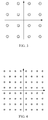
- FIG. 2 is a first implementation schematic diagram of a corresponding relationship between locations of light sources and a constellation diagram according to the present invention
- the constellation modulation is the QPSK modulation in FIG. 2
- the placement locations of the luminescent light sources are as shown in FIG. 2
- double-loop circles represent 4 luminescent light sources respectively corresponding to different constellation points in the FIG. 2
- FIG. 3 is a second implementation schematic diagram of a corresponding relationship between locations of light sources and a constellation diagram according to the present invention
- the constellation modulation is the 16QAM modulation in FIG. 3
- the placement locations of the luminescent light sources are as shown in FIG. 3
- double-loop circles represent 16 luminescent light sources respectively corresponding to different constellation points in the FIG. 3.
- FIG. 4 is a third implementation schematic diagram of a corresponding relationship between locations of light sources and a constellation diagram according to the present invention
- the constellation modulation is the 64QAM modulation in FIG. 4
- the placement locations of the luminescent light sources are as shown in FIG. 4
- double-loop circles represent 64 luminescent light sources respectively corresponding to different constellation points in the FIG. 4 .
- each luminescent light source can be independent, and it also can be a luminescent point that can be independently opened in a luminescent panel. It should be noted that a separation distance between the luminescent points is required to satisfy that the receiving end can identify different luminescent points, and with respect to how to specifically determine the separation distance between the luminescent points, it should be easily implemented by the people skilled in the art according to the actual conditions, which is not limited here.
- mapping the modulated signal to the corresponding luminescent light source includes: according to the preset mapping relationship between the constellation modulation signal and the location where the luminescent light source is located, mapping a signal of a constellation point on which the constellation modulation is currently performed to a luminescent light source corresponding to the constellation point. After the constellation modulation is performed, a throughput of transmitting data streams becomes n times of not performing the constellation modulation.
- step before performing constellation modulation on the data to be sent, it further includes: performing encoding on the data to be sent, and performing constellation modulation on an encoded signal.
- the specific implementation of the encoding and constellation modulation belongs to the common technical means of the people skilled in the art, which will not be repeated here.
- step 101 the data to be sent are transmitted to a receiving end through an optical signal, and the receiving end converts the received optical signal into an electrical signal.
- transmitting the data to be sent to the receiving end through the optical signal includes: opening the corresponding luminescent light source, and transmitting the data to be sent to the receiving end through the optical signal.
- opening the corresponding luminescent light source specifically includes: driving the electrical signal on which the constellation modulation is performed, and opening a luminescent light source on a constellation point corresponding to the modulated signal, thereby completing a conversion from the electrical signal to the optical signal.
- the receiving terminal converting the received optical signal into the electrical signal belongs to the common technical means of the people skilled in the art, and the specific implementation thereof is not used to limit the protection scope of the present invention, which will not be repeated here.
- the receiving terminal converts the received optical signal into the electrical signal, it further includes: performing filter shaping processing on the electrical signal obtained through conversion.
- the specific implementation belongs to the common technical means of the people skilled in the art, which is not used to limit the protection scope of the present invention, and will not be repeated here.
- step 102 the receiving end determines a constellation modulation signal according to a luminescent light source corresponding to the received signal, and demodulates the constellation modulation signal to obtain received data.
- the method also includes: pre-positioning a location of the luminescent light source in a constellation diagram. That is to say, before the communication, the sending end simultaneously opens all luminescent light sources corresponding to constellation modulation in different modulation modes (or simultaneously opens luminescent light sources in part of particular locations), and the receiving end identifies a location of each luminescent light source corresponding to each constellation point in different modulation modes by positioning a light source matrix, thereby establishing a mapping relationship between a constellation modulation signal and a location where the luminescent light source is located consistent with that of the sending end at the receiving end.
- determining the constellation modulation signal according to the luminescent light source corresponding to the received signal in the step includes: mapping a location of the luminescent light source where the received optical signal is located to a constellation modulation signal corresponding to the constellation point according to the established mapping relationship between the constellation modulation signal and the location where the luminescent light source is located.
- processing including demodulation and decoding, etc. is performed on the mapped constellation modulation signal on the constellation point to obtain the received data.
- the specific implementation belongs to the common technical means of the people skilled in the art, which will not be repeated here.
- the sending end places light sources of the visible light according a constellation diagram form of the constellation modulation, and maps the signal obtained after the constellation modulation is performed on the data to be sent to a luminescent light source corresponding to the location of the constellation point and drives the luminescent light source, thereby transmitting the data to be sent to the receiving end through the optical signal; and the receiving terminal determines a constellation modulation signal corresponding to the constellation point according to the location of the luminescent light source, to acquire the data from the sending end.
- the visible light communication is implemented, which meets the demand for application scenarios of the visible light in the future.
- the present invention also provides a system for implementing visible light communication, and as shown in FIG. 5 , a sending end and a receiving end are included, wherein, the sending end is configured to: after performing constellation modulation on data to be sent, map a modulated signal to a corresponding luminescent light source; and transmit the data to be sent to the receiving end through an optical signal; and the receiving end is configured to: receive the optical signal from the sending end and convert the optical signal into an electrical signal; and determine a constellation modulation signal according to a luminescent light source corresponding to the received signal, and demodulate the constellation modulation signal to obtain received data.
- the sending end is configured to: after performing constellation modulation on data to be sent, map a modulated signal to a corresponding luminescent light source; and transmit the data to be sent to the receiving end through an optical signal
- the receiving end is configured to: receive the optical signal from the sending end and convert the optical signal into an electrical signal; and determine a constellation modulation signal according to a luminescent light source corresponding to the
- the sending end at least includes: a signal preprocessing unit, a mapping unit and a signal output unit, wherein, the signal preprocessing unit is configured to: perform preprocessing on the data to be sent and then output the data to be sent to the mapping unit, wherein the preprocessing can include encoding and constellation modulation; the mapping unit, in which a mapping relationship between a constellation modulation signal and a location where the luminescent light source is located is set, is configured to: according to the set mapping relationship, map the modulated signal to the corresponding luminescent light source and then output the modulated signal to the signal output unit; and the signal output unit is configured to: convert an electrical signal from the mapping unit into an optical signal, and transmit the optical signal obtained through conversion to the receiving end.
- the signal preprocessing unit is configured to: perform preprocessing on the data to be sent and then output the data to be sent to the mapping unit, wherein the preprocessing can include encoding and constellation modulation
- the mapping unit in which a mapping relationship between a constellation modulation signal and
- each luminescent light source can be independent, and it also can be a luminescent point that can be independently opened in a luminescent panel. It should be noted that a separation distance between the luminescent points is required to satisfy that the receiving end can identify different luminescent points, and with respect to how to specifically determine the separation distance between the luminescent points, it should be easily implemented by the people skilled in the art according to the actual conditions, which is not limited here.
- the receiving terminal at least includes: a signal receiving unit, an inverse mapping unit and a signal processing unit, wherein, the signal receiving unit is configured to: convert the optical signal from the sending end into the electrical signal and then output the electrical signal to the inverse mapping unit; and it is further configured to perform filter shaping processing on the received optical signal.
- the inverse mapping unit is used to: according to an established mapping relationship between a constellation modulation signal and a location where the luminescent light source is located, map a location of the luminescent light source where the received optical signal is located to a constellation modulation signal corresponding to a constellation point, and output the obtained constellation modulation signal to the signal processing unit; and the signal processing unit is configured to: perform processing on the constellation modulation signal from the inverse mapping unit to obtain the data sent by the sending end.
- the processing therein includes modulation and decoding and so on.
- the sending end is also configured to: simultaneously open all luminescent light sources corresponding to constellation modulation in different modulation modes, or simultaneously open luminescent light sources in part of particular locations; the receiving end is also configured to: identify a location of each luminescent light source corresponding to each constellation point in different modulation modes by positioning a light source matrix, and establish a mapping relationship between a constellation modulation signal and a location where the luminescent light source is located consistent with that of the sending end.
- location calibration such as a plurality of location possibilities corresponding to the QPSK, 16QAM and 64QAM modulation modes shown in FGI. 2 to FIG. 4 , the receiving end is just required to indentify the location by positioning the light source matrix.
- the specific implementation belongs to the common knowledge of the people skilled in the art, which is not used to limit the protection scope of the present invention.
- the number of the luminescent light sources is 4; when the constellation modulation is quadrature amplitude modulation with 16 kinds of symbols (16QAM), the number of the luminescent light sources is 16; and when the constellation modulation is quadrature amplitude modulation with 64 kinds of symbols (64QAM), the number of the luminescent light sources is 64.
- QPSK quadrature phase shift keying
- the present invention also provides a sending apparatus for implementing visible light communication, which is configured to: after performing constellation modulation on data to be sent, map a modulated signal to a corresponding luminescent light source; and send the data to be sent by means of optical signal.
- a signal preprocessing unit, a mapping unit and a signal output unit are at least included, wherein, the signal preprocessing unit is configured to: perform preprocessing on the data to be sent and then output the data to be sent to the mapping unit, wherein the preprocessing can include encoding and constellation modulation;
- the mapping unit in which a mapping relationship between a constellation modulation signal and a location where the luminescent light source is located is set, is configured to: map the modulated signal to the corresponding luminescent light source according to the set mapping relationship and then output the modulated signal to the signal output unit; and the signal output unit is configured to: convert an electrical signal from the mapping unit into an optical signal, and transmit the optical signal obtained through conversion to a receiving end.
- the sending apparatus is also configured to: simultaneously open all luminescent light sources corresponding to constellation modulation in different modulation modes, or simultaneously open luminescent light sources in part of particular locations.
- the present invention also provides a receiving apparatus for implementing visible light communication, which is configured to: convert a received optical signal into an electrical signal; and determine a constellation modulation signal according to a luminescent light source corresponding to the received signal, and demodulate the constellation modulation signal to obtain received data.
- a signal receiving unit, an inverse mapping unit and a signal processing unit are at least included, wherein, the signal receiving unit is configured to: convert an optical signal from a sending end into an electrical signal and then output the electrical signal to the inverse mapping unit; and it is further configured to perform filter shaping processing on the received optical signal.
- the inverse mapping unit is configured to: according to an established mapping relationship between a constellation modulation signal and a location where the luminescent light source is located, map a location of the luminescent light source where the received optical signal is located to a constellation modulation signal corresponding to a constellation point, and output the obtained constellation modulation signal to the signal processing unit; and the signal processing unit is configured to: perform processing on the constellation modulation signal from the inverse mapping unit to obtain the data sent by the sending end.
- the processing therein includes modulation and decoding and so on.
- the receiving apparatus is also configured to: by recording a location of each luminescent light source corresponding to each constellation point in different modulation modes, establish a mapping relationship between a constellation modulation signal and a location where the luminescent light source is located consistent with that of the sending apparatus.
- the sending end places light sources of the visible light according a constellation diagram form of the constellation modulation, and maps the signal obtained after the constellation modulation is performed on the data to be sent to a luminescent light source corresponding to the location of the constellation point and drives the luminescent light source, thereby transmitting the data to be sent to the receiving end through the optical signal; and the receiving terminal determines a constellation modulation signal corresponding to the constellation point according to the location of the luminescent light source, to acquire the data from the sending end.
- the visible light communication is implemented, which meets the demand for application scenarios of the visible light in the future.
Abstract

Description
- The present invention relates to the visible light communication technology, and particularly, to a method and system for implementing visible light communication, a sending apparatus and a receiving apparatus.
- The wireless communication technology using the visible light has attracted attention from the academic circles and industrial circles in recent years. In particular, while the lighting equipment using light-emitting elements such as a light emitting diode (LED) and so on is widely used, the feasibility research on using a semiconductor LED to implement the visible light communication covered by the wireless communication network is ongoing. The appropriate approach of combining the visible light communication with a wireless sensor network, a wireless local area network (WLAN) and a power-line communication system is also in the discussion. It has been able to prove that such commination mode will be one of the alternative short-distance and ultra-wideband commination modes in the future.
- As the light-emitting components used for the high-speed optical data communication, the influence on the human body or medical apparatus should be considered, and the LED has been regarded as the most powerful candidate light-emitting device at present. Meanwhile, in the optical communication, a data rate is dependent on a response speed of the light-emitting device. Therefore, a light-emitting device with the higher-speed response performance such as a laser diode (LD) or a super luminescent diode (SLD) also attracts much attention.
- The basic principle of implementing the visible light communication is that: a certain kind of modulation such as pulse width modulation (PWM), pulse position/frequency modulation (PPM) or pulse amplitude modulation (PAM) is performed on the light emitted by the light-emitting device; the modulated light energy is used as data to be transmitted, and transmitted through a spatial channel and received by a photoelectric detector (a sensor) on the target device; and the photoelectric detector converts the received optical signal into an electrical signal and then demodulates the sent data through the follow-up processing. The target device can be a common portable device attached with such function of transmitting the data through the visible light, such as a mobile phone, a digital camera and a notebook computer and so on. Similar to the constitution of the wireless local area network, the portable terminals constitute the nodes in the network, that is, the visible light communication technology can serve as the local area network technology or the underlying technology applied in an access network.
- According to the future application scenarios and characteristics of the visible light, the multiple input multiple output (MIMO) may become the mainstream application mode in various scenarios. Moreover, there will be more and more various portable devices equipped with cameras. It is not difficult to imagine that using various LEDs as an information releasing system and various portable/mobile terminals as a receiving system is a simple and convenient communication mode. At present, there has been no specific method for implementing the visible light communication in the industry.
- The present invention provides a method and system for implementing visible light communication, a sending apparatus and a receiving apparatus, which can implement the visible light communication, to meet the demand for application scenarios of the visible light in the future.
- In order to solve the above technical problem, the present invention discloses a method for implementing visible light communication, which comprises: after performing constellation modulation on data to be sent, a sending end mapping a modulated signal to a corresponding luminescent light source; and
transmitting the data to be sent to a receiving end through an optical signal, and the receiving end converting the received optical signal into an electrical signal; and
the receiving end determining a constellation modulation signal according to a luminescent light source corresponding to the received signal, and demodulating the constellation modulation signal to obtain received data. - Preferably, before the method, it further comprises: performing encoding on the data to be sent, and performing constellation modulation on an encoded signal.
- Preferably, before the method, it further comprises: presetting a mapping relationship between a constellation modulation signal and a location where the luminescent light source is located;
said mapping a modulated signal to a corresponding luminescent light source comprises: mapping a signal of a constellation point on which the constellation modulation is performed to a luminescent light source corresponding to the constellation point, according to the mapping relationship. - Preferably, said transmitting the data to be sent to a receiving end through an optical signal comprises: opening the corresponding luminescent light source, and transmitting the data to be sent to the receiving end through the optical signal.
- Preferably, said opening the corresponding luminescent light source comprises: driving the electrical signal on which the constellation modulation is performed, and opening a luminescent light source on a constellation point corresponding to the modulated signal.
- Preferably, after the receiving end converts the received optical signal into the electrical signal, the method further comprises: performing filter shaping processing on the electrical signal obtained through the conversion.
- Preferably, when the receiving end is started, the method further comprises: pre-positioning a location of the luminescent light source in a constellation diagram.
- Preferably, the pre-positioning comprises: the sending end simultaneously opening all luminescent light sources corresponding to constellation modulation in different modulation modes, or simultaneously opening luminescent light sources in part of particular locations; and
the receiving end identifying a location of each luminescent light source corresponding to each constellation point in different modulation modes by positioning a light source matrix, and establishing a mapping relationship between a constellation modulation signal and a location where the luminescent light source is located consistent with that of the sending end. - Preferably, determining a constellation modulation signal according to the luminescent light source corresponding to the received signal comprises: according to the established mapping relationship, mapping a location of the luminescent light source where the received optical signal is located to a constellation modulation signal corresponding to the constellation point.
- The present invention further provides a system for implementing visible light communication, which comprises: a sending end and a receiving end;
the sending end is configured to: after performing constellation modulation on data to be sent, map a modulated signal to a corresponding luminescent light source; and transmit the data to be sent to the receiving end through an optical signal; and
the receiving end is configured to: receive the optical signal from the sending end and convert the optical signal into an electrical signal; and determine a constellation modulation signal according to a luminescent light source corresponding to the received signal, and demodulate the constellation modulation signal to obtain received data. - Preferably, the sending end at least comprises: a signal preprocessing unit, a mapping unit and a signal output unit, wherein,
the signal preprocessing unit is configured to: perform preprocessing on the data to be sent and then output the preprocessed data to be sent to the mapping unit, wherein the preprocessing comprises encoding and constellation modulation;
the mapping unit is configured to: be set with a mapping relationship between a constellation modulation signal and a location where the luminescent light source is located; and map the modulated signal to the corresponding luminescent light source according to the set mapping relationship and then output the modulated signal to the signal output unit; and
the signal output unit is configured to: convert an electrical signal from the mapping unit into an optical signal, and transmit the optical signal obtained through the conversion to the receiving end. - Preferably, the luminescent light source is independent, or is a luminescent point independently opened in a luminescent panel.
- Preferably, the receiving terminal at least comprises: a signal receiving unit, an inverse mapping unit and a signal processing unit, wherein,
the signal receiving unit is configured to: convert the optical signal from the sending end into the electrical signal and then output the electrical signal to the inverse mapping unit;
the inverse mapping unit is configured to: according to an established mapping relationship between a constellation modulation signal and a location where the luminescent light source is located, map a location of the luminescent light source where the received optical signal is located into a constellation modulation signal corresponding to a constellation point, and output the obtained constellation modulation signal to the signal processing unit; and
the signal processing unit is configured to: perform processing on the constellation modulation signal from the inverse mapping unit to obtain the data sent by the sending end; wherein the processing comprises modulation and decoding. - The signal receiving unit is further configured to: perform filter shaping processing on the received optical signal.
- The sending end is further configured to: simultaneously open all luminescent light sources corresponding to constellation modulation in different modulation modes, or simultaneously open luminescent light sources in part of particular locations;
the receiving end is further configured to: identify a location of each luminescent light source corresponding to each constellation point in different modulation modes by positioning a light source matrix, and establish a mapping relationship between a constellation modulation signal and a location where the luminescent light source is located consistent with that of the sending end. - Preferably, when the constellation modulation is quaternary phase shift keying (QPSK) signal modulation, a number of the luminescent light sources is 4;
when the constellation modulation is quadrature amplitude modulation with 16 kinds of symbols (16QAM), a number of the luminescent light sources is 16; and
when the constellation modulation is quadrature amplitude modulation with 64 kinds of symbols (64QAM), a number of the luminescent light sources is 64. - The present invention further provides a sending apparatus, which is configured to: after performing constellation modulation on data to be sent, map a modulated signal to a corresponding luminescent light source; and send the data to be sent through an optical signal.
- Preferably, the sending apparatus at least comprises: a signal preprocessing unit, a mapping unit and a signal output unit, wherein,
the signal preprocessing unit is configured to: perform preprocessing on the data to be sent and then output the preprocessed data to be sent to the mapping unit, wherein the preprocessing comprises encoding and constellation modulation;
the mapping unit is configured to: be set with a mapping relationship between a constellation modulation signal and a location where the luminescent light source is located; and map the modulated signal to the corresponding luminescent light source according to the set mapping relationship and then output the modulated signal to the signal output unit; and
the signal output unit is configured to: convert an electrical signal from the mapping unit into an optical signal, and transmit the optical signal obtained through the conversion to a receiving end. - Preferably, the sending apparatus is further configured to: simultaneously open all luminescent light sources corresponding to constellation modulation in different modulation mode, or simultaneously open luminescent light sources in part of particular locations.
- When the constellation modulation is quaternary phase shift keying (QPSK) signal modulation, a number of the luminescent light sources is 4;
when the constellation modulation is quadrature amplitude modulation with 16 kinds of symbols (16QAM), a number of the luminescent light sources is 16; and
when the constellation modulation is quadrature amplitude modulation with 64 kinds of symbols (64QAM), a number of the luminescent light sources is 64. - The present invention further provides a receiving apparatus, which is configured to: convert a received optical signal into an electrical signal; and determine a constellation modulation signal according to a luminescent light source corresponding to the received signal, and demodulate the constellation modulation signal to obtain received data.
- Preferably, the receiving apparatus at least comprises: a signal receiving unit, an inverse mapping unit and a signal processing unit, wherein,
the signal receiving unit is configured to: convert an optical signal from a sending end into an electrical signal and then output the electrical signal to the inverse mapping unit;
the inverse mapping unit is configured to: according to an established mapping relationship between a constellation modulation signal and a location where the luminescent light source is located, map a location of the luminescent light source where the received optical signal is located to a constellation modulation signal corresponding to a constellation point, and output the obtained constellation modulation signal to the signal processing unit; and
the signal processing unit is configured to: perform processing on the constellation modulation signal from the inverse mapping unit to obtain the data sent by the sending end; wherein the processing comprises modulation and decoding. - Preferably, the signal receiving unit is further configured to: perform filter shaping processing on the received optical signal.
- Preferably, the receiving apparatus is further configured to: identify a location of each luminescent light source corresponding to each constellation point in different modulation modes by positioning a light source matrix, and establish a mapping relationship between a constellation modulation signal and a location where the luminescent light source is located consistent with that of a sending apparatus.
- The technical scheme of the present application comprises: after performing constellation modulation on data to be sent, a sending end mapping a modulated signal to a corresponding luminescent light source; and transmitting the data to be sent to a receiving end through an optical signal, and the receiving end converting a received optical signal into an electrical signal; and the receiving end determining a constellation modulation signal according to a luminescent light source corresponding to the received signal, and demodulating the constellation modulation signal to obtain received data. In the method of the embodiment of the present invention, the sending end places light sources of the visible light according a constellation diagram form of the constellation modulation, and maps the signal obtained after the constellation modulation is performed on the data to be sent to a luminescent light source corresponding to the location of the constellation point and drives the luminescent light source, thereby transmitting the data to be sent to the receiving end through the optical signal; and the receiving terminal determines a constellation modulation signal corresponding to the constellation point according to the location of the luminescent light source, to acquire the data from the sending end. With the above method, the visible light communication is implemented, which meets the demand for application scenarios of the visible light in the future.
- Here, the described accompanying drawings are used to provide a further understanding of the present invention and constitute a part of the present application. The schematic embodiments and illustrations thereof of the present invention are used to explain the present invention, but do not constitute an inappropriate limitation on the present invention. In the drawings:
-
FIG. 1 is a flow chart of a method for implementing visible light communication according to the embodiment of the present invention. -
FIG. 2 is a first implementation schematic diagram of a corresponding relationship between locations of light sources and a constellation diagram according to the present invention. -
FIG. 3 is a second implementation schematic diagram of a corresponding relationship between locations of light sources and a constellation diagram according to the present invention. -
FIG. 4 is a third implementation schematic diagram of a corresponding relationship between locations of light sources and a constellation diagram according to the present invention. -
FIG. 5 is a schematic diagram of a composition structure of a system for implementing visible light communication according to the embodiment of the present invention. -
FIG. 1 is a flow chart of a method for implementing visible light communication according to the present invention, and as shown inFIG. 1 , the following steps are included. - In
step 100, after performing constellation modulation on data to be sent, a sending end maps a modulated signal to a corresponding luminescent light source. - In the step, luminescent light sources of the visible light are placed in simulation to the form of locations of the constellation points after the constellation modulation is performed, and a mapping relationship between a constellation modulation signal and a location where the luminescent light source is located is preset. According to characteristics of the constellation modulation, for example, when a quaternary phase shift keying (QPSK) signal is a 2bit byte and QPSK modulation is adopted, 4 constellation points can be generated, and thus 4 luminescent light sources are required to correspond to the 4 constellation points respectively; for another example, when quadrature amplitude modulation with 16 kinds of symbols (16QAM) is a 4bit byte and the 16QAM modulation is adopted, 16 constellation points can be generated, and thus 16 luminescent light sources are required to correspond to the 16 constellation points respectively; and for another example, when quadrature amplitude modulation with 64 kinds of symbols (64QAM) is a 6bit byte and the 64QAM modulation is adopted, 64 constellation points can be generated, and thus 64 luminescent light sources are required to correspond to the 64 constellation points respectively, and so forth. It is not difficult to understand that other constellation modulation is on the analogy of this: 2n luminescent light sources can transmit n-byte constellation modulation information at each moment, and during the data transmission, the luminescent light source corresponding to only one constellation point is opened at each moment.
- For example,
FIG. 2 is a first implementation schematic diagram of a corresponding relationship between locations of light sources and a constellation diagram according to the present invention, the constellation modulation is the QPSK modulation inFIG. 2 , the placement locations of the luminescent light sources are as shown inFIG. 2 , and double-loop circles represent 4 luminescent light sources respectively corresponding to different constellation points in theFIG. 2 .FIG. 3 is a second implementation schematic diagram of a corresponding relationship between locations of light sources and a constellation diagram according to the present invention, the constellation modulation is the 16QAM modulation inFIG. 3 , the placement locations of the luminescent light sources are as shown inFIG. 3 , and double-loop circles represent 16 luminescent light sources respectively corresponding to different constellation points in theFIG. 3. FIG. 4 is a third implementation schematic diagram of a corresponding relationship between locations of light sources and a constellation diagram according to the present invention, the constellation modulation is the 64QAM modulation inFIG. 4 , the placement locations of the luminescent light sources are as shown inFIG. 4 , and double-loop circles represent 64 luminescent light sources respectively corresponding to different constellation points in theFIG. 4 . - Wherein, each luminescent light source can be independent, and it also can be a luminescent point that can be independently opened in a luminescent panel. It should be noted that a separation distance between the luminescent points is required to satisfy that the receiving end can identify different luminescent points, and with respect to how to specifically determine the separation distance between the luminescent points, it should be easily implemented by the people skilled in the art according to the actual conditions, which is not limited here.
- In the step, mapping the modulated signal to the corresponding luminescent light source includes: according to the preset mapping relationship between the constellation modulation signal and the location where the luminescent light source is located, mapping a signal of a constellation point on which the constellation modulation is currently performed to a luminescent light source corresponding to the constellation point. After the constellation modulation is performed, a throughput of transmitting data streams becomes n times of not performing the constellation modulation.
- In the step, before performing constellation modulation on the data to be sent, it further includes: performing encoding on the data to be sent, and performing constellation modulation on an encoded signal. Wherein, the specific implementation of the encoding and constellation modulation belongs to the common technical means of the people skilled in the art, which will not be repeated here.
- In
step 101, the data to be sent are transmitted to a receiving end through an optical signal, and the receiving end converts the received optical signal into an electrical signal. - In the step, transmitting the data to be sent to the receiving end through the optical signal includes: opening the corresponding luminescent light source, and transmitting the data to be sent to the receiving end through the optical signal. Wherein, opening the corresponding luminescent light source specifically includes: driving the electrical signal on which the constellation modulation is performed, and opening a luminescent light source on a constellation point corresponding to the modulated signal, thereby completing a conversion from the electrical signal to the optical signal.
- The receiving terminal converting the received optical signal into the electrical signal belongs to the common technical means of the people skilled in the art, and the specific implementation thereof is not used to limit the protection scope of the present invention, which will not be repeated here.
- In the step, after the receiving terminal converts the received optical signal into the electrical signal, it further includes: performing filter shaping processing on the electrical signal obtained through conversion. The specific implementation belongs to the common technical means of the people skilled in the art, which is not used to limit the protection scope of the present invention, and will not be repeated here.
- In
step 102, the receiving end determines a constellation modulation signal according to a luminescent light source corresponding to the received signal, and demodulates the constellation modulation signal to obtain received data. - Before the step, when the receiving end equipment is started, the method also includes: pre-positioning a location of the luminescent light source in a constellation diagram. That is to say, before the communication, the sending end simultaneously opens all luminescent light sources corresponding to constellation modulation in different modulation modes (or simultaneously opens luminescent light sources in part of particular locations), and the receiving end identifies a location of each luminescent light source corresponding to each constellation point in different modulation modes by positioning a light source matrix, thereby establishing a mapping relationship between a constellation modulation signal and a location where the luminescent light source is located consistent with that of the sending end at the receiving end. Therefore,
determining the constellation modulation signal according to the luminescent light source corresponding to the received signal in the step includes: mapping a location of the luminescent light source where the received optical signal is located to a constellation modulation signal corresponding to the constellation point according to the established mapping relationship between the constellation modulation signal and the location where the luminescent light source is located. - In the step, processing including demodulation and decoding, etc., is performed on the mapped constellation modulation signal on the constellation point to obtain the received data. The specific implementation belongs to the common technical means of the people skilled in the art, which will not be repeated here.
- In the method of the present invention, the sending end places light sources of the visible light according a constellation diagram form of the constellation modulation, and maps the signal obtained after the constellation modulation is performed on the data to be sent to a luminescent light source corresponding to the location of the constellation point and drives the luminescent light source, thereby transmitting the data to be sent to the receiving end through the optical signal; and the receiving terminal determines a constellation modulation signal corresponding to the constellation point according to the location of the luminescent light source, to acquire the data from the sending end. Through the method of the present invention, the visible light communication is implemented, which meets the demand for application scenarios of the visible light in the future.
- The present invention also provides a system for implementing visible light communication, and as shown in
FIG. 5 , a sending end and a receiving end are included, wherein,
the sending end is configured to: after performing constellation modulation on data to be sent, map a modulated signal to a corresponding luminescent light source; and transmit the data to be sent to the receiving end through an optical signal; and
the receiving end is configured to: receive the optical signal from the sending end and convert the optical signal into an electrical signal; and determine a constellation modulation signal according to a luminescent light source corresponding to the received signal, and demodulate the constellation modulation signal to obtain received data. - The sending end at least includes: a signal preprocessing unit, a mapping unit and a signal output unit, wherein,
the signal preprocessing unit is configured to: perform preprocessing on the data to be sent and then output the data to be sent to the mapping unit, wherein the preprocessing can include encoding and constellation modulation;
the mapping unit, in which a mapping relationship between a constellation modulation signal and a location where the luminescent light source is located is set, is configured to: according to the set mapping relationship, map the modulated signal to the corresponding luminescent light source and then output the modulated signal to the signal output unit; and
the signal output unit is configured to: convert an electrical signal from the mapping unit into an optical signal, and transmit the optical signal obtained through conversion to the receiving end. - Wherein, each luminescent light source can be independent, and it also can be a luminescent point that can be independently opened in a luminescent panel. It should be noted that a separation distance between the luminescent points is required to satisfy that the receiving end can identify different luminescent points, and with respect to how to specifically determine the separation distance between the luminescent points, it should be easily implemented by the people skilled in the art according to the actual conditions, which is not limited here.
- The receiving terminal at least includes: a signal receiving unit, an inverse mapping unit and a signal processing unit, wherein,
the signal receiving unit is configured to: convert the optical signal from the sending end into the electrical signal and then output the electrical signal to the inverse mapping unit; and it is further configured to perform filter shaping processing on the received optical signal. - The inverse mapping unit is used to: according to an established mapping relationship between a constellation modulation signal and a location where the luminescent light source is located, map a location of the luminescent light source where the received optical signal is located to a constellation modulation signal corresponding to a constellation point, and output the obtained constellation modulation signal to the signal processing unit; and
the signal processing unit is configured to: perform processing on the constellation modulation signal from the inverse mapping unit to obtain the data sent by the sending end. The processing therein includes modulation and decoding and so on. - Furthermore,
the sending end is also configured to: simultaneously open all luminescent light sources corresponding to constellation modulation in different modulation modes, or simultaneously open luminescent light sources in part of particular locations;
the receiving end is also configured to: identify a location of each luminescent light source corresponding to each constellation point in different modulation modes by positioning a light source matrix, and establish a mapping relationship between a constellation modulation signal and a location where the luminescent light source is located consistent with that of the sending end. It should be noted that, in order to perform location calibration, such as a plurality of location possibilities corresponding to the QPSK, 16QAM and 64QAM modulation modes shown in FGI. 2 toFIG. 4 , the receiving end is just required to indentify the location by positioning the light source matrix. The specific implementation belongs to the common knowledge of the people skilled in the art, which is not used to limit the protection scope of the present invention. - When the constellation modulation is quaternary phase shift keying (QPSK) signal modulation, the number of the luminescent light sources is 4; when the constellation modulation is quadrature amplitude modulation with 16 kinds of symbols (16QAM), the number of the luminescent light sources is 16; and when the constellation modulation is quadrature amplitude modulation with 64 kinds of symbols (64QAM), the number of the luminescent light sources is 64.
- The present invention also provides a sending apparatus for implementing visible light communication, which is configured to: after performing constellation modulation on data to be sent, map a modulated signal to a corresponding luminescent light source; and send the data to be sent by means of optical signal. A signal preprocessing unit, a mapping unit and a signal output unit are at least included, wherein,
the signal preprocessing unit is configured to: perform preprocessing on the data to be sent and then output the data to be sent to the mapping unit, wherein the preprocessing can include encoding and constellation modulation;
the mapping unit, in which a mapping relationship between a constellation modulation signal and a location where the luminescent light source is located is set, is configured to: map the modulated signal to the corresponding luminescent light source according to the set mapping relationship and then output the modulated signal to the signal output unit; and
the signal output unit is configured to: convert an electrical signal from the mapping unit into an optical signal, and transmit the optical signal obtained through conversion to a receiving end. - The sending apparatus is also configured to: simultaneously open all luminescent light sources corresponding to constellation modulation in different modulation modes, or simultaneously open luminescent light sources in part of particular locations.
- The present invention also provides a receiving apparatus for implementing visible light communication, which is configured to: convert a received optical signal into an electrical signal; and determine a constellation modulation signal according to a luminescent light source corresponding to the received signal, and demodulate the constellation modulation signal to obtain received data. A signal receiving unit, an inverse mapping unit and a signal processing unit are at least included, wherein,
the signal receiving unit is configured to: convert an optical signal from a sending end into an electrical signal and then output the electrical signal to the inverse mapping unit; and it is further configured to perform filter shaping processing on the received optical signal. - The inverse mapping unit is configured to: according to an established mapping relationship between a constellation modulation signal and a location where the luminescent light source is located, map a location of the luminescent light source where the received optical signal is located to a constellation modulation signal corresponding to a constellation point, and output the obtained constellation modulation signal to the signal processing unit; and
the signal processing unit is configured to: perform processing on the constellation modulation signal from the inverse mapping unit to obtain the data sent by the sending end. The processing therein includes modulation and decoding and so on. - The receiving apparatus is also configured to: by recording a location of each luminescent light source corresponding to each constellation point in different modulation modes, establish a mapping relationship between a constellation modulation signal and a location where the luminescent light source is located consistent with that of the sending apparatus.
- The above description is only the preferred embodiments of the present invention, which is not used to limit the protection scope of the present invention. All the modifications, equivalent substitutions, and improvements, etc. made within the spirit and principle of the present invention shall fall into the protection scope of the present invention.
- In the method of the embodiment of the present invention, the sending end places light sources of the visible light according a constellation diagram form of the constellation modulation, and maps the signal obtained after the constellation modulation is performed on the data to be sent to a luminescent light source corresponding to the location of the constellation point and drives the luminescent light source, thereby transmitting the data to be sent to the receiving end through the optical signal; and the receiving terminal determines a constellation modulation signal corresponding to the constellation point according to the location of the luminescent light source, to acquire the data from the sending end. With the above method, the visible light communication is implemented, which meets the demand for application scenarios of the visible light in the future.
Claims (24)
- A method for implementing visible light communication, comprising: after performing constellation modulation on data to be sent, a sending end mapping a modulated signal to a corresponding luminescent light source; and
transmitting the data to be sent to a receiving end through an optical signal, and the receiving end converting the received optical signal into an electrical signal; and
the receiving end determining a constellation modulation signal according to a luminescent light source corresponding to the received signal, and demodulating the constellation modulation signal to obtain received data. - The method according to claim 1, wherein, before the method, the following is further comprised: performing encoding on the data to be sent, and performing constellation modulation on an encoded signal.
- The method according to claim 1 or 2, wherein, before the method, the following is further comprised: presetting a mapping relationship between the constellation modulation signal and a location where the luminescent light source is located;
said mapping a modulated signal to a corresponding luminescent light source comprises: mapping a signal of a constellation point on which the constellation modulation is performed to a luminescent light source corresponding to the constellation point according to the mapping relationship. - The method according to claim 3, wherein, said transmitting the data to be sent to a receiving end through an optical signal comprises: opening the corresponding luminescent light source, and transmitting the data to be sent to the receiving end through the optical signal.
- The method according to claim 4, wherein, said opening the corresponding luminescent light source comprises: driving an electrical signal on which the constellation modulation is performed, and opening a luminescent light source on a constellation point corresponding to the modulated signal.
- The method according to claim 1 or 2, wherein, after the receiving end converts the received optical signal into the electrical signal, the method further comprises:performing filter shaping processing on the electrical signal obtained through the conversion.
- The method according to claim 6, wherein, when the receiving end is started, the method further comprises: pre-positioning a location of the luminescent light source in a constellation diagram.
- The method according to claim 7, wherein, the pre-positioning comprises: the sending end simultaneously opening all luminescent light sources corresponding to constellation modulation in different modulation modes, or simultaneously opening luminescent light sources in part of particular locations; and
the receiving end identifying a location of each luminescent light source corresponding to each constellation point in different modulation modes by positioning a light source matrix, and establishing a mapping relationship between a constellation modulation signal and a location where the luminescent light source is located consistent with that of the sending end. - The method according to claim 8, wherein, said determining a constellation modulation signal according to a luminescent light source corresponding to the received signal comprises: according to the established mapping relationship, mapping a location of the luminescent light source where the received optical signal is located to a constellation modulation signal corresponding to the constellation point.
- A system for implementing visible light communication, comprising: a sending end and a receiving end; wherein
the sending end is configured to: after performing constellation modulation on data to be sent, map a modulated signal to a corresponding luminescent light source; and transmit the data to be sent to the receiving end through an optical signal; and
the receiving end is configured to: receive the optical signal from the sending end and convert the optical signal into an electrical signal; and determine a constellation modulation signal according to a luminescent light source corresponding to the received signal, and demodulate the constellation modulation signal to obtain received data. - The system according to claim 10, wherein, the sending end at least comprises: a signal preprocessing unit, a mapping unit and a signal output unit, wherein,
the signal preprocessing unit is configured to: perform preprocessing on the data to be sent and then output the preprocessed data to be sent to the mapping unit, wherein the preprocessing comprises encoding and constellation modulation;
the mapping unit is configured to: be set with a mapping relationship between a constellation modulation signal and a location where the luminescent light source is located; and according to the set mapping relationship, map the modulated signal to the corresponding luminescent light source and then output the modulated signal to the signal output unit; and
the signal output unit is configured to: convert an electrical signal from the mapping unit into an optical signal, and transmit the optical signal obtained through the conversion to the receiving end. - The apparatus according to claim 10 or 11, wherein, the luminescent light source is independent, or is a luminescent point independently opened in a luminescent panel.
- The system according to claim 10, wherein, the receiving end at least comprises: a signal receiving unit, an inverse mapping unit and a signal processing unit, wherein,
the signal receiving unit is configured to: convert the optical signal from the sending end into the electrical signal and then output the electrical signal to the inverse mapping unit;
the inverse mapping unit is configured to: according to an established mapping relationship between a constellation modulation signal and a location where the luminescent light source is located, map a location of the luminescent light source where the received optical signal is located to a constellation modulation signal corresponding to a constellation point, and output the obtained constellation modulation signal to the signal processing unit; and
the signal processing unit is configured to: perform processing on the constellation modulation signal from the inverse mapping unit to obtain the data sent by the sending end; wherein the processing comprises modulation and decoding. - The system according to claim 13, wherein, the signal receiving unit is further configured to: perform filter shaping processing on the received optical signal.
- The system according to claim 10, wherein, the sending end is further configured to: simultaneously open all luminescent light sources corresponding to constellation modulation in different modulation modes, or simultaneously open luminescent light sources in part of particular locations;
the receiving end is further configured to: identify a location of each luminescent light source corresponding to each constellation point in different modulation modes by positioning a light source matrix, and establish a mapping relationship between a constellation modulation signal and a location where the luminescent light source is located consistent with that of the sending end. - The system according to claim 12, wherein, when the constellation modulation is quaternary phase shift keying (QPSK) signal modulation, a number of the luminescent light sources is 4;
when the constellation modulation is quadrature amplitude modulation with 16 kinds of symbols (16QAM), a number of the luminescent light sources is 16; and
when the constellation modulation is quadrature amplitude modulation with 64 kinds of symbols (64QAM), a number of the luminescent light sources is 64. - A sending apparatus, configured to: after performing constellation modulation on data to be sent, map a modulated signal to a corresponding luminescent light source; and send the data to be sent through an optical signal.
- The sending apparatus according to claim 17, wherein, the sending apparatus at least comprises: a signal preprocessing unit, a mapping unit and a signal output unit, wherein,
the signal preprocessing unit is configured to: perform preprocessing on the data to be sent and then output the preprocessed data to be sent to the mapping unit, wherein the preprocessing comprises encoding and constellation modulation;
the mapping unit is configured to: be set with a mapping relationship between a constellation modulation signal and a location where the luminescent light source is located; and map the modulated signal to the corresponding luminescent light source according to the set mapping relationship, and then output the modulated signal to the signal output unit; and
the signal output unit is configured to: convert an electrical signal from the mapping unit into an optical signal, and transmit the optical signal obtained through the conversion to a receiving end. - The sending apparatus according to claim 17 or 18, wherein, the sending apparatus is further configured to: simultaneously open all luminescent light sources corresponding to constellation modulation in different modulation modes, or simultaneously open luminescent light sources in part of particular locations.
- The sending apparatus according to claim 19, wherein, when the constellation modulation is quaternary phase shift keying (QPSK) signal modulation, a number of the luminescent light sources is 4;
when the constellation modulation is quadrature amplitude modulation with 16 kinds of symbols (16QAM), a number of the luminescent light sources is 16; and
when the constellation modulation is quadrature amplitude modulation with 64 kinds of symbols (64QAM), a number of the luminescent light sources is 64. - A receiving apparatus, configured to: convert a received optical signal into an electrical signal; and determine a constellation modulation signal according to a luminescent light source corresponding to the received signal, and demodulate the constellation modulation signal to obtain received data.
- The receiving apparatus according to claim 21, wherein the receiving apparatus at least comprises: a signal receiving unit, an inverse mapping unit and a signal processing unit, wherein,
the signal receiving unit is configured to: convert an optical signal from a sending end into an electrical signal and then output the electrical signal to the inverse mapping unit;
the inverse mapping unit is configured to: according to an established mapping relationship between a constellation modulation signal and a location where the luminescent light source is located, map a location of the luminescent light source where the received optical signal is located to a constellation modulation signal corresponding to a constellation point, and output the obtained constellation modulation signal to the signal processing unit; and
the signal processing unit is configured to: perform processing on the constellation modulation signal from the inverse mapping unit to obtain the data sent by the sending end; wherein the processing comprises modulation and decoding. - The receiving apparatus according to claim 22, wherein, the signal receiving unit is further configured to: perform filter shaping processing on the received optical signal.
- The receiving apparatus according to any one of claims 21 to 23, wherein, the receiving apparatus is further configured to: identify a location of each luminescent light source corresponding to each constellation point in different modulation modes by positioning a light source matrix, and establish a mapping relationship between a constellation modulation signal and a location where the luminescent light source is located consistent with that of a sending apparatus.
Applications Claiming Priority (2)
| Application Number | Priority Date | Filing Date | Title |
|---|---|---|---|
| CN201310169108.9A CN104144015B (en) | 2013-05-09 | 2013-05-09 | Realize method, system and the sending device and reception device of visible light communication |
| PCT/CN2013/082353 WO2014180080A1 (en) | 2013-05-09 | 2013-08-27 | Method and system for implementing visible-light communication, sending apparatus, and receiving apparatus |
Publications (3)
| Publication Number | Publication Date |
|---|---|
| EP2996263A1 true EP2996263A1 (en) | 2016-03-16 |
| EP2996263A4 EP2996263A4 (en) | 2016-05-04 |
| EP2996263B1 EP2996263B1 (en) | 2018-10-17 |
Family
ID=51853090
Family Applications (1)
| Application Number | Title | Priority Date | Filing Date |
|---|---|---|---|
| EP13883909.7A Not-in-force EP2996263B1 (en) | 2013-05-09 | 2013-08-27 | Method and system for implementing visible-light communication, sending apparatus, and receiving apparatus |
Country Status (5)
| Country | Link |
|---|---|
| US (1) | US9906297B2 (en) |
| EP (1) | EP2996263B1 (en) |
| CN (1) | CN104144015B (en) |
| DK (1) | DK2996263T3 (en) |
| WO (1) | WO2014180080A1 (en) |
Cited By (1)
| Publication number | Priority date | Publication date | Assignee | Title |
|---|---|---|---|---|
| CN108365895A (en) * | 2017-08-14 | 2018-08-03 | 广东顺德中山大学卡内基梅隆大学国际联合研究院 | A method of construction spherical surface visible light communication modulation constellation |
Families Citing this family (9)
| Publication number | Priority date | Publication date | Assignee | Title |
|---|---|---|---|---|
| CN107735642A (en) * | 2015-06-23 | 2018-02-23 | 富士通株式会社 | Position measuring device, position measurement method and position finding program |
| CN105553554B (en) * | 2016-01-25 | 2017-12-12 | 中国人民解放军信息工程大学 | Visible light communication signal constellation (in digital modulation) design method, apparatus and system |
| CN105680937B (en) * | 2016-01-25 | 2018-10-19 | 中国人民解放军信息工程大学 | Signal detecting method, device and visible light communication system |
| WO2018040041A1 (en) * | 2016-08-31 | 2018-03-08 | 华为技术有限公司 | Method, apparatus, and system for signal modulation and demodulation |
| CN107147441B (en) * | 2017-05-02 | 2019-06-18 | 中国人民解放军信息工程大学 | The detection method and device of signal |
| CN107493133B (en) * | 2017-05-16 | 2019-10-15 | 中国人民解放军信息工程大学 | A kind of additivity uniquely can decompose the construction method and its system of constellation group |
| CN107270908A (en) * | 2017-05-24 | 2017-10-20 | 大连民族大学 | Visible ray alignment system and the air navigation aid using the system in supermarket shopping guide |
| WO2019134176A1 (en) | 2018-01-08 | 2019-07-11 | 华为技术有限公司 | Camera communication method and device |
| WO2020166732A1 (en) * | 2019-02-12 | 2020-08-20 | 엘지전자 주식회사 | Method for transmitting signals in visible light communications and terminal for same |
Family Cites Families (31)
| Publication number | Priority date | Publication date | Assignee | Title |
|---|---|---|---|---|
| JP3382314B2 (en) * | 1993-08-24 | 2003-03-04 | キヤノン株式会社 | Communication device and communication device control method |
| JPH08331057A (en) * | 1995-03-27 | 1996-12-13 | Sony Corp | Optical signal transmitter, optical signal receiver, and optical signal transmitter-receiver |
| US8188878B2 (en) * | 2000-11-15 | 2012-05-29 | Federal Law Enforcement Development Services, Inc. | LED light communication system |
| JP2004201131A (en) * | 2002-12-19 | 2004-07-15 | Hitachi Kokusai Electric Inc | Wireless device |
| US7689130B2 (en) * | 2005-01-25 | 2010-03-30 | Koninklijke Philips Electronics N.V. | Method and apparatus for illumination and communication |
| WO2008050729A1 (en) * | 2006-10-23 | 2008-05-02 | Panasonic Corporation | Optical space transmission system using visible light and infrared light |
| JP2009031876A (en) * | 2007-07-24 | 2009-02-12 | Sharp Corp | Image processor, image forming device and image reader therewith, image processing method, image processing program and recording medium recording image processing program |
| US7969297B2 (en) | 2008-05-14 | 2011-06-28 | Sony Ericsson Mobile Communications Ab | System and method for determining positioning information via modulated light |
| US8195054B2 (en) * | 2008-11-26 | 2012-06-05 | Samsung Electronics Co., Ltd | Apparatus and method for transmitting and receiving an information symbol in a visible light communication system for color code modulation |
| CN101826899B (en) * | 2009-03-02 | 2013-06-05 | 华为技术有限公司 | Signal transmission method and device based on relay |
| PL2406902T3 (en) | 2009-03-13 | 2017-12-29 | Philips Lighting Holding B.V. | Illumination device and method for embedding data symbols in a luminance output |
| US20100247112A1 (en) * | 2009-03-31 | 2010-09-30 | Soo-Young Chang | System and Method for Visible Light Communications |
| CN101547182B (en) * | 2009-04-17 | 2011-07-20 | 北京大学 | Method for mapping and demapping QAM constellation diagrams |
| CN101924722B (en) * | 2009-06-15 | 2013-06-26 | 华为技术有限公司 | Method and device for generating and receiving OOFDM (Orthogonal Frequency Division Multiplexing) signal and wavelength division multiplexing system |
| US20100322635A1 (en) | 2009-06-18 | 2010-12-23 | Sony Ericsson Mobile Communications Ab | Using ambient led light for broadcasting info and navigation |
| EP2337245B1 (en) * | 2009-12-17 | 2013-04-10 | Alcatel Lucent | Optical OFDM transmission having a variable transmission rate |
| CN101714971B (en) * | 2009-12-22 | 2012-06-06 | 北京邮电大学 | Passive optical network communication method, optical-fiber network unit, and optical line terminal |
| EP2591581A1 (en) * | 2010-07-05 | 2013-05-15 | Nokia Siemens Networks OY | Method and device for data processing in an optical communication network |
| US9203544B2 (en) * | 2010-12-03 | 2015-12-01 | Wuhan Research Institute Of Posts And Telecommunications | Optical communication system, device and method employing advanced coding and high modulation order |
| CN102684819B (en) * | 2011-03-15 | 2015-06-03 | 华为技术有限公司 | Data transmission method, relative device and relative system |
| KR20130009132A (en) * | 2011-07-14 | 2013-01-23 | 현대자동차주식회사 | Apparatus and method for controlling a vehicle using visible light communication |
| TWI441140B (en) * | 2011-07-18 | 2014-06-11 | Ampower Technology Co Ltd | Led driving system and display device using the same |
| CN102904665A (en) * | 2011-07-25 | 2013-01-30 | 华为技术有限公司 | Control channel transmission method, device and system |
| US9418115B2 (en) * | 2011-07-26 | 2016-08-16 | Abl Ip Holding Llc | Location-based mobile services and applications |
| CN102394723A (en) * | 2011-10-31 | 2012-03-28 | 哈尔滨工程大学 | White-light LED modulation method combined with asymmetric Turbo coding |
| GB2496379A (en) * | 2011-11-04 | 2013-05-15 | Univ Edinburgh | A freespace optical communication system which exploits the rolling shutter mechanism of a CMOS camera |
| KR20130116483A (en) * | 2012-04-05 | 2013-10-24 | 한국전자통신연구원 | Apparatus and method for transmitting and receiving for visible light communication |
| US9917644B2 (en) * | 2012-10-09 | 2018-03-13 | Booz Allen Hamilton Inc. | Method and system for data transmission and communication using imperceptible differences in visible light |
| US20150318925A1 (en) * | 2012-11-30 | 2015-11-05 | The University Court Of The University Of Edinburgh | Communication apparatus and method |
| US10142018B2 (en) * | 2013-03-06 | 2018-11-27 | Cree, Inc. | Visible light communication via solid state lighting devices |
| US9468232B2 (en) * | 2014-09-17 | 2016-10-18 | Mario DeGuzman | Cigarillo splitter |
-
2013
- 2013-05-09 CN CN201310169108.9A patent/CN104144015B/en not_active Expired - Fee Related
- 2013-08-27 EP EP13883909.7A patent/EP2996263B1/en not_active Not-in-force
- 2013-08-27 WO PCT/CN2013/082353 patent/WO2014180080A1/en active Application Filing
- 2013-08-27 DK DK13883909.7T patent/DK2996263T3/en active
- 2013-08-27 US US14/889,442 patent/US9906297B2/en not_active Expired - Fee Related
Cited By (2)
| Publication number | Priority date | Publication date | Assignee | Title |
|---|---|---|---|---|
| CN108365895A (en) * | 2017-08-14 | 2018-08-03 | 广东顺德中山大学卡内基梅隆大学国际联合研究院 | A method of construction spherical surface visible light communication modulation constellation |
| CN108365895B (en) * | 2017-08-14 | 2020-10-23 | 广东顺德中山大学卡内基梅隆大学国际联合研究院 | Method for constructing spherical visible light communication modulation constellation diagram |
Also Published As
| Publication number | Publication date |
|---|---|
| US20160127039A1 (en) | 2016-05-05 |
| DK2996263T3 (en) | 2019-01-21 |
| EP2996263A4 (en) | 2016-05-04 |
| WO2014180080A1 (en) | 2014-11-13 |
| EP2996263B1 (en) | 2018-10-17 |
| CN104144015B (en) | 2018-08-21 |
| CN104144015A (en) | 2014-11-12 |
| US9906297B2 (en) | 2018-02-27 |
Similar Documents
| Publication | Publication Date | Title |
|---|---|---|
| US9906297B2 (en) | Method and system for implementing visible-light communication, sending apparatus, and receiving apparatus | |
| US10382129B2 (en) | Transmission of identifiers using visible light communication | |
| Leba et al. | LiFi—The path to a new way of communication | |
| US9548815B2 (en) | Apparatus for visible light communications in accordance with UFSOOK and FSK dimming | |
| Chen et al. | A framework for simultaneous message broadcasting using CDMA-based visible light communications | |
| Delgado et al. | Design and implementation of an Ethernet-VLC interface for broadcast transmissions | |
| CN103869284A (en) | Visible light communication-based indoor positioning system and method | |
| KR101364390B1 (en) | Method and apparatus visible signal generation for data transmitting frame in visible light communication | |
| del Campo-Jimenez et al. | A VLC-based beacon location system for mobile applications | |
| Kamsula | Design and implementation of a bi-directional visible light communication testbed | |
| CN104980218A (en) | Optical-filter-free visible light communication system | |
| CN103873142B (en) | The data sending, receiving method and device of visible light communication, Transmission system | |
| Durgun et al. | VLC4WoT: Visible light communication for web of things | |
| KR102010640B1 (en) | Apparatus of multi-user Full-duplex visible light communication | |
| CN104601236A (en) | Reflection principle based visible light communication system and method | |
| Siddiqui et al. | LED-based visible light communication system for low data rate point-and-grab applications | |
| US9673902B2 (en) | Visible light communication system | |
| Das et al. | Performance analysis of color-independent visible light communication using a color-space-based constellation diagram and modulation scheme | |
| CN106487449B (en) | A kind of optic communication digital walkie-talkie and its signal strength display system, method | |
| CN106027162A (en) | Optical communication system and method | |
| KR20150132781A (en) | Method and Apparatus for Indoor Positioning by Using Beacon and Visible Light Signal | |
| CN107508634A (en) | Visible light communication system and its method | |
| CN110365410B (en) | Data transmission method, device and system based on visible light communication | |
| KR101508873B1 (en) | Optical communication transmitter and receiver | |
| KR101587732B1 (en) | A system and a method for VLC |
Legal Events
| Date | Code | Title | Description |
|---|---|---|---|
| PUAI | Public reference made under article 153(3) epc to a published international application that has entered the european phase |
Free format text: ORIGINAL CODE: 0009012 |
|
| 17P | Request for examination filed |
Effective date: 20151209 |
|
| AK | Designated contracting states |
Kind code of ref document: A1 Designated state(s): AL AT BE BG CH CY CZ DE DK EE ES FI FR GB GR HR HU IE IS IT LI LT LU LV MC MK MT NL NO PL PT RO RS SE SI SK SM TR |
|
| AX | Request for extension of the european patent |
Extension state: BA ME |
|
| A4 | Supplementary search report drawn up and despatched |
Effective date: 20160406 |
|
| RIC1 | Information provided on ipc code assigned before grant |
Ipc: H04B 10/116 20130101AFI20160331BHEP Ipc: H04L 27/34 20060101ALI20160331BHEP |
|
| DAX | Request for extension of the european patent (deleted) | ||
| GRAP | Despatch of communication of intention to grant a patent |
Free format text: ORIGINAL CODE: EPIDOSNIGR1 |
|
| STAA | Information on the status of an ep patent application or granted ep patent |
Free format text: STATUS: GRANT OF PATENT IS INTENDED |
|
| RIC1 | Information provided on ipc code assigned before grant |
Ipc: H04B 10/556 20130101ALI20180424BHEP Ipc: H04L 27/34 20060101ALI20180424BHEP Ipc: H04B 10/116 20130101AFI20180424BHEP |
|
| INTG | Intention to grant announced |
Effective date: 20180517 |
|
| GRAS | Grant fee paid |
Free format text: ORIGINAL CODE: EPIDOSNIGR3 |
|
| GRAA | (expected) grant |
Free format text: ORIGINAL CODE: 0009210 |
|
| STAA | Information on the status of an ep patent application or granted ep patent |
Free format text: STATUS: THE PATENT HAS BEEN GRANTED |
|
| AK | Designated contracting states |
Kind code of ref document: B1 Designated state(s): AL AT BE BG CH CY CZ DE DK EE ES FI FR GB GR HR HU IE IS IT LI LT LU LV MC MK MT NL NO PL PT RO RS SE SI SK SM TR |
|
| REG | Reference to a national code |
Ref country code: GB Ref legal event code: FG4D |
|
| REG | Reference to a national code |
Ref country code: CH Ref legal event code: EP |
|
| REG | Reference to a national code |
Ref country code: IE Ref legal event code: FG4D |
|
| REG | Reference to a national code |
Ref country code: DE Ref legal event code: R096 Ref document number: 602013045402 Country of ref document: DE Ref country code: AT Ref legal event code: REF Ref document number: 1055236 Country of ref document: AT Kind code of ref document: T Effective date: 20181115 |
|
| REG | Reference to a national code |
Ref country code: DK Ref legal event code: T3 Effective date: 20190107 |
|
| REG | Reference to a national code |
Ref country code: NL Ref legal event code: MP Effective date: 20181017 |
|
| REG | Reference to a national code |
Ref country code: LT Ref legal event code: MG4D |
|
| REG | Reference to a national code |
Ref country code: AT Ref legal event code: MK05 Ref document number: 1055236 Country of ref document: AT Kind code of ref document: T Effective date: 20181017 |
|
| PG25 | Lapsed in a contracting state [announced via postgrant information from national office to epo] |
Ref country code: NL Free format text: LAPSE BECAUSE OF FAILURE TO SUBMIT A TRANSLATION OF THE DESCRIPTION OR TO PAY THE FEE WITHIN THE PRESCRIBED TIME-LIMIT Effective date: 20181017 |
|
| PG25 | Lapsed in a contracting state [announced via postgrant information from national office to epo] |
Ref country code: ES Free format text: LAPSE BECAUSE OF FAILURE TO SUBMIT A TRANSLATION OF THE DESCRIPTION OR TO PAY THE FEE WITHIN THE PRESCRIBED TIME-LIMIT Effective date: 20181017 Ref country code: AT Free format text: LAPSE BECAUSE OF FAILURE TO SUBMIT A TRANSLATION OF THE DESCRIPTION OR TO PAY THE FEE WITHIN THE PRESCRIBED TIME-LIMIT Effective date: 20181017 Ref country code: BG Free format text: LAPSE BECAUSE OF FAILURE TO SUBMIT A TRANSLATION OF THE DESCRIPTION OR TO PAY THE FEE WITHIN THE PRESCRIBED TIME-LIMIT Effective date: 20190117 Ref country code: NO Free format text: LAPSE BECAUSE OF FAILURE TO SUBMIT A TRANSLATION OF THE DESCRIPTION OR TO PAY THE FEE WITHIN THE PRESCRIBED TIME-LIMIT Effective date: 20190117 Ref country code: LT Free format text: LAPSE BECAUSE OF FAILURE TO SUBMIT A TRANSLATION OF THE DESCRIPTION OR TO PAY THE FEE WITHIN THE PRESCRIBED TIME-LIMIT Effective date: 20181017 Ref country code: FI Free format text: LAPSE BECAUSE OF FAILURE TO SUBMIT A TRANSLATION OF THE DESCRIPTION OR TO PAY THE FEE WITHIN THE PRESCRIBED TIME-LIMIT Effective date: 20181017 Ref country code: IS Free format text: LAPSE BECAUSE OF FAILURE TO SUBMIT A TRANSLATION OF THE DESCRIPTION OR TO PAY THE FEE WITHIN THE PRESCRIBED TIME-LIMIT Effective date: 20190217 Ref country code: LV Free format text: LAPSE BECAUSE OF FAILURE TO SUBMIT A TRANSLATION OF THE DESCRIPTION OR TO PAY THE FEE WITHIN THE PRESCRIBED TIME-LIMIT Effective date: 20181017 Ref country code: HR Free format text: LAPSE BECAUSE OF FAILURE TO SUBMIT A TRANSLATION OF THE DESCRIPTION OR TO PAY THE FEE WITHIN THE PRESCRIBED TIME-LIMIT Effective date: 20181017 Ref country code: PL Free format text: LAPSE BECAUSE OF FAILURE TO SUBMIT A TRANSLATION OF THE DESCRIPTION OR TO PAY THE FEE WITHIN THE PRESCRIBED TIME-LIMIT Effective date: 20181017 |
|
| PG25 | Lapsed in a contracting state [announced via postgrant information from national office to epo] |
Ref country code: SE Free format text: LAPSE BECAUSE OF FAILURE TO SUBMIT A TRANSLATION OF THE DESCRIPTION OR TO PAY THE FEE WITHIN THE PRESCRIBED TIME-LIMIT Effective date: 20181017 Ref country code: AL Free format text: LAPSE BECAUSE OF FAILURE TO SUBMIT A TRANSLATION OF THE DESCRIPTION OR TO PAY THE FEE WITHIN THE PRESCRIBED TIME-LIMIT Effective date: 20181017 Ref country code: PT Free format text: LAPSE BECAUSE OF FAILURE TO SUBMIT A TRANSLATION OF THE DESCRIPTION OR TO PAY THE FEE WITHIN THE PRESCRIBED TIME-LIMIT Effective date: 20190217 Ref country code: GR Free format text: LAPSE BECAUSE OF FAILURE TO SUBMIT A TRANSLATION OF THE DESCRIPTION OR TO PAY THE FEE WITHIN THE PRESCRIBED TIME-LIMIT Effective date: 20190118 Ref country code: RS Free format text: LAPSE BECAUSE OF FAILURE TO SUBMIT A TRANSLATION OF THE DESCRIPTION OR TO PAY THE FEE WITHIN THE PRESCRIBED TIME-LIMIT Effective date: 20181017 |
|
| REG | Reference to a national code |
Ref country code: DE Ref legal event code: R097 Ref document number: 602013045402 Country of ref document: DE |
|
| PG25 | Lapsed in a contracting state [announced via postgrant information from national office to epo] |
Ref country code: CZ Free format text: LAPSE BECAUSE OF FAILURE TO SUBMIT A TRANSLATION OF THE DESCRIPTION OR TO PAY THE FEE WITHIN THE PRESCRIBED TIME-LIMIT Effective date: 20181017 Ref country code: IT Free format text: LAPSE BECAUSE OF FAILURE TO SUBMIT A TRANSLATION OF THE DESCRIPTION OR TO PAY THE FEE WITHIN THE PRESCRIBED TIME-LIMIT Effective date: 20181017 |
|
| PLBE | No opposition filed within time limit |
Free format text: ORIGINAL CODE: 0009261 |
|
| STAA | Information on the status of an ep patent application or granted ep patent |
Free format text: STATUS: NO OPPOSITION FILED WITHIN TIME LIMIT |
|
| PG25 | Lapsed in a contracting state [announced via postgrant information from national office to epo] |
Ref country code: SK Free format text: LAPSE BECAUSE OF FAILURE TO SUBMIT A TRANSLATION OF THE DESCRIPTION OR TO PAY THE FEE WITHIN THE PRESCRIBED TIME-LIMIT Effective date: 20181017 Ref country code: RO Free format text: LAPSE BECAUSE OF FAILURE TO SUBMIT A TRANSLATION OF THE DESCRIPTION OR TO PAY THE FEE WITHIN THE PRESCRIBED TIME-LIMIT Effective date: 20181017 Ref country code: SM Free format text: LAPSE BECAUSE OF FAILURE TO SUBMIT A TRANSLATION OF THE DESCRIPTION OR TO PAY THE FEE WITHIN THE PRESCRIBED TIME-LIMIT Effective date: 20181017 Ref country code: EE Free format text: LAPSE BECAUSE OF FAILURE TO SUBMIT A TRANSLATION OF THE DESCRIPTION OR TO PAY THE FEE WITHIN THE PRESCRIBED TIME-LIMIT Effective date: 20181017 |
|
| 26N | No opposition filed |
Effective date: 20190718 |
|
| PG25 | Lapsed in a contracting state [announced via postgrant information from national office to epo] |
Ref country code: SI Free format text: LAPSE BECAUSE OF FAILURE TO SUBMIT A TRANSLATION OF THE DESCRIPTION OR TO PAY THE FEE WITHIN THE PRESCRIBED TIME-LIMIT Effective date: 20181017 |
|
| PGFP | Annual fee paid to national office [announced via postgrant information from national office to epo] |
Ref country code: MC Payment date: 20191028 Year of fee payment: 7 Ref country code: DE Payment date: 20191022 Year of fee payment: 7 Ref country code: IE Payment date: 20191023 Year of fee payment: 7 |
|
| PGFP | Annual fee paid to national office [announced via postgrant information from national office to epo] |
Ref country code: FR Payment date: 20191029 Year of fee payment: 7 Ref country code: DK Payment date: 20191028 Year of fee payment: 7 |
|
| PG25 | Lapsed in a contracting state [announced via postgrant information from national office to epo] |
Ref country code: TR Free format text: LAPSE BECAUSE OF FAILURE TO SUBMIT A TRANSLATION OF THE DESCRIPTION OR TO PAY THE FEE WITHIN THE PRESCRIBED TIME-LIMIT Effective date: 20181017 |
|
| PGFP | Annual fee paid to national office [announced via postgrant information from national office to epo] |
Ref country code: GB Payment date: 20191018 Year of fee payment: 7 |
|
| PG25 | Lapsed in a contracting state [announced via postgrant information from national office to epo] |
Ref country code: LU Free format text: LAPSE BECAUSE OF NON-PAYMENT OF DUE FEES Effective date: 20190827 Ref country code: LI Free format text: LAPSE BECAUSE OF NON-PAYMENT OF DUE FEES Effective date: 20190831 Ref country code: CH Free format text: LAPSE BECAUSE OF NON-PAYMENT OF DUE FEES Effective date: 20190831 |
|
| REG | Reference to a national code |
Ref country code: BE Ref legal event code: MM Effective date: 20190831 |
|
| PG25 | Lapsed in a contracting state [announced via postgrant information from national office to epo] |
Ref country code: BE Free format text: LAPSE BECAUSE OF NON-PAYMENT OF DUE FEES Effective date: 20190831 |
|
| REG | Reference to a national code |
Ref country code: DE Ref legal event code: R119 Ref document number: 602013045402 Country of ref document: DE |
|
| REG | Reference to a national code |
Ref country code: DK Ref legal event code: EBP Effective date: 20200831 |
|
| PG25 | Lapsed in a contracting state [announced via postgrant information from national office to epo] |
Ref country code: MC Free format text: LAPSE BECAUSE OF NON-PAYMENT OF DUE FEES Effective date: 20200831 |
|
| GBPC | Gb: european patent ceased through non-payment of renewal fee |
Effective date: 20200827 |
|
| PG25 | Lapsed in a contracting state [announced via postgrant information from national office to epo] |
Ref country code: CY Free format text: LAPSE BECAUSE OF FAILURE TO SUBMIT A TRANSLATION OF THE DESCRIPTION OR TO PAY THE FEE WITHIN THE PRESCRIBED TIME-LIMIT Effective date: 20181017 |
|
| PG25 | Lapsed in a contracting state [announced via postgrant information from national office to epo] |
Ref country code: DE Free format text: LAPSE BECAUSE OF NON-PAYMENT OF DUE FEES Effective date: 20210302 Ref country code: MT Free format text: LAPSE BECAUSE OF FAILURE TO SUBMIT A TRANSLATION OF THE DESCRIPTION OR TO PAY THE FEE WITHIN THE PRESCRIBED TIME-LIMIT Effective date: 20181017 Ref country code: HU Free format text: LAPSE BECAUSE OF FAILURE TO SUBMIT A TRANSLATION OF THE DESCRIPTION OR TO PAY THE FEE WITHIN THE PRESCRIBED TIME-LIMIT; INVALID AB INITIO Effective date: 20130827 Ref country code: FR Free format text: LAPSE BECAUSE OF NON-PAYMENT OF DUE FEES Effective date: 20200831 |
|
| PG25 | Lapsed in a contracting state [announced via postgrant information from national office to epo] |
Ref country code: GB Free format text: LAPSE BECAUSE OF NON-PAYMENT OF DUE FEES Effective date: 20200827 Ref country code: IE Free format text: LAPSE BECAUSE OF NON-PAYMENT OF DUE FEES Effective date: 20200827 Ref country code: DK Free format text: LAPSE BECAUSE OF NON-PAYMENT OF DUE FEES Effective date: 20200831 |
|
| PG25 | Lapsed in a contracting state [announced via postgrant information from national office to epo] |
Ref country code: MK Free format text: LAPSE BECAUSE OF FAILURE TO SUBMIT A TRANSLATION OF THE DESCRIPTION OR TO PAY THE FEE WITHIN THE PRESCRIBED TIME-LIMIT Effective date: 20181017 |