EP2996122A1 - Transformer - Google Patents
Transformer Download PDFInfo
- Publication number
- EP2996122A1 EP2996122A1 EP14794993.7A EP14794993A EP2996122A1 EP 2996122 A1 EP2996122 A1 EP 2996122A1 EP 14794993 A EP14794993 A EP 14794993A EP 2996122 A1 EP2996122 A1 EP 2996122A1
- Authority
- EP
- European Patent Office
- Prior art keywords
- coil
- bobbin
- transformer
- flange
- protrusion
- Prior art date
- Legal status (The legal status is an assumption and is not a legal conclusion. Google has not performed a legal analysis and makes no representation as to the accuracy of the status listed.)
- Withdrawn
Links
Images

Classifications
-
- H—ELECTRICITY
- H01—ELECTRIC ELEMENTS
- H01F—MAGNETS; INDUCTANCES; TRANSFORMERS; SELECTION OF MATERIALS FOR THEIR MAGNETIC PROPERTIES
- H01F27/00—Details of transformers or inductances, in general
- H01F27/28—Coils; Windings; Conductive connections
- H01F27/32—Insulating of coils, windings, or parts thereof
- H01F27/324—Insulation between coil and core, between different winding sections, around the coil; Other insulation structures
- H01F27/325—Coil bobbins
-
- H—ELECTRICITY
- H01—ELECTRIC ELEMENTS
- H01F—MAGNETS; INDUCTANCES; TRANSFORMERS; SELECTION OF MATERIALS FOR THEIR MAGNETIC PROPERTIES
- H01F27/00—Details of transformers or inductances, in general
- H01F27/28—Coils; Windings; Conductive connections
- H01F27/2823—Wires
-
- H—ELECTRICITY
- H01—ELECTRIC ELEMENTS
- H01F—MAGNETS; INDUCTANCES; TRANSFORMERS; SELECTION OF MATERIALS FOR THEIR MAGNETIC PROPERTIES
- H01F27/00—Details of transformers or inductances, in general
- H01F27/28—Coils; Windings; Conductive connections
- H01F27/2866—Combination of wires and sheets
-
- H—ELECTRICITY
- H01—ELECTRIC ELEMENTS
- H01F—MAGNETS; INDUCTANCES; TRANSFORMERS; SELECTION OF MATERIALS FOR THEIR MAGNETIC PROPERTIES
- H01F27/00—Details of transformers or inductances, in general
- H01F27/28—Coils; Windings; Conductive connections
- H01F27/2871—Pancake coils
-
- H—ELECTRICITY
- H01—ELECTRIC ELEMENTS
- H01F—MAGNETS; INDUCTANCES; TRANSFORMERS; SELECTION OF MATERIALS FOR THEIR MAGNETIC PROPERTIES
- H01F5/00—Coils
- H01F5/02—Coils wound on non-magnetic supports, e.g. formers
- H01F2005/022—Coils wound on non-magnetic supports, e.g. formers wound on formers with several winding chambers separated by flanges, e.g. for high voltage applications
-
- H—ELECTRICITY
- H01—ELECTRIC ELEMENTS
- H01F—MAGNETS; INDUCTANCES; TRANSFORMERS; SELECTION OF MATERIALS FOR THEIR MAGNETIC PROPERTIES
- H01F5/00—Coils
- H01F5/02—Coils wound on non-magnetic supports, e.g. formers
- H01F2005/025—Coils wound on non-magnetic supports, e.g. formers wound on coaxial arrangement of two or more formers
Definitions
- the present invention relates to a transformer having a configuration preferably used in a switching power supply and other high-current-specification apparatus.
- a coil using a conductor having a large cross-sectional area is used to suppress heat generation due to high current.
- Patent Literature 1 described below proposes a transformer using a flat copper wire having a large cross-sectional area and wound in an edgewise manner as a high-voltage coil and a low-voltage coil.
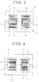
- Figure 3 shows a transformer of this type formed as follows: A stranded wire is wound around a bobbin 1 to form a high-voltage coil 2; the coil 2 is accommodated in a pair of bottomed, cylindrical, insulating cases 3 and 4; a low-voltage coil 5, which is produced in a stamping process in which a metal flat plate is stamped in an open ring shape, is disposed coaxially with the high-voltage coil 2 on each of a bottom plate 3a of the case 3 and a top plate 4a of the case 4; and middle legs of a pair of E-shaped cores 6 are inserted into the low-voltage coils 5 and the bobbin 1 and outer legs of the cores 6 are located around the outer circumferences of the low-voltage coils 5 and the cases 3 and 4 to form a closed magnetic circuit.
- reference character 7 denotes an insulating plate having a circular ring plate shape interposed between each of the low-voltage coils 5 and the corresponding core 6.
- the cases 3 and 4 and the plates 7 ensure creeping distances between the high-voltage coil 2 and the low-voltage coils 5 and between the high-voltage coil 2 and the cores 6.
- the two cases 3 and 4 and the two plates 7 are required to ensure the creeping distances described above, undesirably resulting in an increase in the number of parts and hence increases in part manufacturing cost, management cost, assembly cost, and other types of cost.
- the stranded wire that forms the high-voltage coil 2 has poor shape retaining capability, the following problems may arise:
- the wound wire of the high-voltage coil 2 is bent, so that the bent wire approaches a bonding section 5a, which bonds the low-voltage coils 5 to each other, and the creeping distance between the high-voltage coil 2 and the low-voltage coils 5 cannot therefore be ensured; or a drawn wire 2a drawn from the high-voltage coil 2 is bent, so that the creeping distance between the high-voltage coil 2 and the cores 6 cannot be ensured.
- Patent Literature 1 Japanese Patent Laid-Open No. 2000-223320
- the present invention has been made in view of the circumstances described above, and an object of the present invention is to provide a transformer capable of readily ensuring a predetermined insulation distance with no increase in the overall size of the transformer and further capable of reducing the number of constituent parts to achieve cost reduction.
- a first aspect of the present invention (invention described in claim 1) relates to a transformer comprising: a first bobbin having a wire winding section and a flange formed at an end of the wire winding section; a first coil wound around an outer circumference of the wire winding section of the first bobbin; a second coil disposed coaxially with the first coil and adjacent to the flange; and a core disposed around outer circumferences of the first and second coils to form a closed magnetic circuit, wherein a tubular protrusion that axially extends and surrounds the outer circumference of the second coil is formed along an outer circumferential portion of the flange of the first bobbin.
- a second aspect of the present invention is characterized in that in the first form described above (invention described in claim 1), an insulating member having a flat plate shape is disposed between the second coil and the core, and a second protrusion that protrudes into a space between the protrusion and the outer circumference of the second coil is formed on a surface of the insulating member on a side facing the second coil.
- a third aspect of the present invention provides, in the first or second aspect of the invention described above (invention described in claim 1 or 2), a transformer in which the first coil is a high-voltage coil with a stranded wire wound around the wire winding section, and the second coil is a low-voltage coil formed of a metal flat plate shaped in an open circular ring.
- a fourth aspect of the present invention provides, in the first or second aspect of the invention described above (invention described in claim 1 or 2), a transformer in which the first coil is a high-voltage coil with a stranded wire wound around the wire winding section and is disposed in a bottomed, tubular, insulating cover, the second coil is wound around a second bobbin and disposed on a side facing an opening of the insulating cover, and a flange of the second bobbin that is located on the side facing the opening is formed to have a diameter greater than a diameter of the protrusion on the first bobbin.
- the tubular protrusion that axially extends and surrounds the outer circumference of the second coil is formed along the outer circumferential portion of the flange of the first bobbin, around which the first coil is wound, the creeping distance between the first coil and the second coil can be increased by the axial length of the protrusion.
- the length of the protrusion allows a predetermined creeping distance between the first and second coils to be ensured.
- the predetermined insulation distance can be readily ensured with no increase in the overall size of the transformer, and the number of constituent parts can be reduced to achieve cost reduction because no insulating case is required, unlike in the related art.
- the insulating member having a flat plate shape is disposed between the second coil and the core, as in the second aspect of the present invention (invention described in claim 2), forming the second protrusion that protrudes into the space between the protrusion and the outer circumference of the second coil on the surface of the insulating member on the side facing the second coil allows the creeping distance between the first coil and the second coil to be the axial length of the protrusion to which the axial length of the portion where the protrusion and the second protrusion overlap with each other is added.
- the present invention can therefore be readily applied to a higher-current-specification transformer.
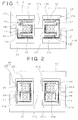
- Figure 1 shows a first embodiment of a transformer according to the present invention
- reference character 10 in Figure 1 denotes a bobbin (first bobbin).
- the bobbin 10 includes a cylindrical wire winding section 10a and flanges 10b, which each has a circular ring plate shape and are integrated with opposite ends of the wire winding section 10a, and a stranded wire is wound in an ⁇ winding manner around the outer circumference of the wire winding section 10a to form a high-voltage coil (first coil) 11.
- a low-voltage coil (second coil) 12 is disposed on the outer surface of each of the flanges 10a at opposite ends of the bobbin 10.
- Each of the low-voltage coils 12 is produced in a stamping process in which a copper plate (metal flat plate) is stamped in an open ring shape and is disposed coaxially with the high-voltage coil 11.
- the bobbin 10, around which the high-voltage coil 11 is wound, and the low-voltage coils 12 are accommodated in an insulating case 13.
- the case 13 has a bottomed, cylindrical shape formed of a bottom plate (insulating member) 14, which has a circular disk plate shape, and a cylindrical sidewall 15, which is so formed that it is integrated with the outer circumferential edge of the bottom plate 14 to surround the outer circumference of the high-voltage coil 11 and the low-voltage coils 12, and the opening of the case 13 is closed with a cap (insulating member) 16.
- a pair of E-shaped cores 17, which form a closed magnetic circuit, are disposed around the outer circumferences of the case 13 and the cap 16 in such a way that the cores 17 face each other.
- a middle leg 17a of each of the E-shaped cores 17 is inserted into the opening of the case 13 and an opening formed in central portions of the cap 16 and further into a through hole in the bobbin 10, and an outer leg 17b of each of the cores 17 is disposed along the sidewall 15 of the case 13.
- a cylindrical protrusion 18 is so formed that it is integrated with an outer circumferential portion of each of the flanges 10b of the bobbin 10, and the protrusions 18 extend in the axial direction of the bobbin 10 and surround the outer circumferences of the low-voltage coils 12.
- a cylindrical second protrusion 19 is formed on and integrated with each of the bottom plate 14 of the case 13 and the surface of the cap 16 on the side facing the low-voltage coils 12, and the protrusions 19 protrude toward the flanges 10b of the bobbin 10 into the spaces between the protrusions 18 and the outer circumferences of the low-voltage coils 12.
- the axial length of the protrusions 18 is so set that in a state in which the bobbin 10 and the low-voltage coils 12 are accommodated in the case 13 and the cap 16 is attached thereto, the front end of each of the protrusions 18 comes into contact with the bottom plate 14 of the case 13 or the cap 16.
- the second protrusions 19 are formed in positions where they accommodate the low-voltage coils 12 and restrict movement of the low-voltage coils 12 in the direction perpendicular to the axial line thereof, and the axial length of the second protrusions 19 is so set that in the state in which the bobbin 10 and the low-voltage coils 12 are accommodated in the case 13 and the cap 16 is attached thereto, the front end of each of the protrusions 19 comes into contact with the corresponding flange 10b of the bobbin 10.
- the cylindrical protrusions 18, which surround the outer circumferences of the low-voltage coils 12, are formed along the outer circumferential edges of the flanges 10b of the bobbin 10, around which the high-voltage coil 11 is wound, and the second protrusions 19, which protrude toward the flanges 10b of the bobbin 10 into the spaces between the protrusions 18 and the outer circumferences of the low-voltage coils 12, are formed on the bottom plate 14 of the case 13 and the surface of the cap 16 on the side facing the low-voltage coils 12.
- a creeping distance L 1 between the high-voltage coil 11 and each of the low-voltage coils 12 is the axial length of the protrusion 18 measured from the outer circumference of the high-voltage coil 11 to which the axial length of the portion where the protrusion and the second protrusion overlap with each other is added.
- the protrusions 18 and the second protrusions 19 described above allow the creeping distance L 1 between the high-voltage coil 11 and each of the low-voltage coils and the creeping distance L 2 between the high-voltage coil 11 and each of the cores 17 to be increased, a required creeping distance can be ensured by appropriately setting the axial length of each of the protrusions 18 and the second protrusions 19.
- Predetermined insulation distances L 1 and L 2 can therefore be readily ensured with no increase in the overall size of the transformer. Further, the number of constituent parts can be reduced to achieve cost reduction, as compared with the number of parts and cost in the related art shown in Figure 3 .
- the second protrusions 19, which are formed on the bottom plate 14 of the case 13 and the cap 16, advantageously allow the low-voltage coils 12 to be extremely readily positioned and assembled.
- FIG. 2 shows a second embodiment of the transformer according to the present invention.
- the E-shaped cores 17 have the same configuration as that shown in Figure 1 and therefore have the same reference character and are described in a simplified manner.
- a high-voltage coil (first coil) 21 which is formed of a stranded wire wound in an ⁇ -winding manner around a wire winding section 20a of a bobbin (first bobbin) 20, and a low-voltage coil (second coil) 23, which is formed of a copper wire or a stranded wire wound in an ⁇ -winding manner around a wire winding section 22a of a bobbin (second bobbin) 22, are axially disposed adjacent to each other.
- the bobbins 20 and 22 axially layered on each other are accommodated in a bottomed, cylindrical case 24.
- the bobbin 20, around which the high-voltage coil 21 is wound, is disposed in a position shifted toward a top plate (insulating member) 25 of the case 24, and the bobbin 22, around which the low-voltage coil 23 is wound, is disposed in a position shifted toward the opening of the case 24.
- a flange 22b of the bobbin 22 on the side facing the opening of the case 24 serves as an insulating member between the low-voltage coil 23 and the corresponding one of the E-shaped cores 17.
- a cylindrical protrusion 26 which axially extends and surrounds the outer circumference of the low-voltage coil 23, is so formed on and integrated with the outer circumferential edge of a flange 20b of the bobbin 20 on the side adjacent to the bobbin 22, around which the low-voltage coil 23 is wound.
- the axial length of the protrusion 26 is so set that in a state in which the two bobbins 20 and 22 are layered on each other, the front end of the protrusion 26 comes into contact with the flange 22b of the bobbin 22 on the side facing the opening of the case 24.
- the outer diameter of the flange 22b that faces the opening is set to be greater than the diameter of the protrusion 26 of the bobbin 20, more specifically, the outer circumferential edge of the flange 22b is closer to a sidewall 27 of the case 24 than the protrusion 26.
- a creeping distance L 1 between the high-voltage coil 21 and the low-voltage coil 23 is increased by the axial length of the protrusion 26 measured from the outer circumference of the high-voltage coil 21.
- a creeping distance L 2 between the low-voltage coil 23 and each of the cores 17 is the length from the outer circumferential edge of the flange 22b of the bobbin 22 to the outer circumference of the low-voltage coil 23.
- the present invention can provide a transformer capable of readily ensuring a predetermined insulation distance with no increase in the overall size of the transformer and further capable of reducing the number of constituent parts to achieve cost reduction.
Landscapes
- Engineering & Computer Science (AREA)
- Power Engineering (AREA)
- Coils Of Transformers For General Uses (AREA)
- Insulating Of Coils (AREA)
Abstract
Description
- The present invention relates to a transformer having a configuration preferably used in a switching power supply and other high-current-specification apparatus.
- In a transformer used in a switching power supply in an electric automobile or any other apparatus, a coil using a conductor having a large cross-sectional area is used to suppress heat generation due to high current.
- For example,
Patent Literature 1 described below proposes a transformer using a flat copper wire having a large cross-sectional area and wound in an edgewise manner as a high-voltage coil and a low-voltage coil. - Further, as another high-current-specification transformer, there is a known transformer using a stranded wire having a small AC resistance value as a high-voltage coil.
-
Figure 3 shows a transformer of this type formed as follows: A stranded wire is wound around abobbin 1 to form a high-voltage coil 2; thecoil 2 is accommodated in a pair of bottomed, cylindrical,insulating cases voltage coil 5, which is produced in a stamping process in which a metal flat plate is stamped in an open ring shape, is disposed coaxially with the high-voltage coil 2 on each of a bottom plate 3a of thecase 3 and a top plate 4a of thecase 4; and middle legs of a pair ofE-shaped cores 6 are inserted into the low-voltage coils 5 and thebobbin 1 and outer legs of thecores 6 are located around the outer circumferences of the low-voltage coils 5 and thecases Figure 3 ,reference character 7 denotes an insulating plate having a circular ring plate shape interposed between each of the low-voltage coils 5 and thecorresponding core 6. - According to the thus configured transformer, the
cases plates 7 ensure creeping distances between the high-voltage coil 2 and the low-voltage coils 5 and between the high-voltage coil 2 and thecores 6. - In the transformer having the configuration described above, however, the two
cases plates 7 are required to ensure the creeping distances described above, undesirably resulting in an increase in the number of parts and hence increases in part manufacturing cost, management cost, assembly cost, and other types of cost. - To avoid the situation described above, it is conceivable to omit the
cases bobbin 8 ensure a creeping distance L as shown inFigure 4 . However, as a result of an increase in the separation distance between the high-voltage coil 2 and the low-voltage coils 5, the following problems arise: The overall size of the transformer increases; and the amount of magnetic flux leakage increases to degrade the characteristics of the transformer. - Further, since the stranded wire that forms the high-
voltage coil 2 has poor shape retaining capability, the following problems may arise: The wound wire of the high-voltage coil 2 is bent, so that the bent wire approaches a bonding section 5a, which bonds the low-voltage coils 5 to each other, and the creeping distance between the high-voltage coil 2 and the low-voltage coils 5 cannot therefore be ensured; or a drawn wire 2a drawn from the high-voltage coil 2 is bent, so that the creeping distance between the high-voltage coil 2 and thecores 6 cannot be ensured. - Patent Literature 1:
Japanese Patent Laid-Open No. 2000-223320 - The present invention has been made in view of the circumstances described above, and an object of the present invention is to provide a transformer capable of readily ensuring a predetermined insulation distance with no increase in the overall size of the transformer and further capable of reducing the number of constituent parts to achieve cost reduction.
- To achieve the object described above, a first aspect of the present invention (invention described in claim 1) relates to a transformer comprising: a first bobbin having a wire winding section and a flange formed at an end of the wire winding section; a first coil wound around an outer circumference of the wire winding section of the first bobbin; a second coil disposed coaxially with the first coil and adjacent to the flange; and a core disposed around outer circumferences of the first and second coils to form a closed magnetic circuit, wherein a tubular protrusion that axially extends and surrounds the outer circumference of the second coil is formed along an outer circumferential portion of the flange of the first bobbin.
- A second aspect of the present invention (invention described in claim 2) is characterized in that in the first form described above (invention described in claim 1), an insulating member having a flat plate shape is disposed between the second coil and the core, and a second protrusion that protrudes into a space between the protrusion and the outer circumference of the second coil is formed on a surface of the insulating member on a side facing the second coil.
- Further, a third aspect of the present invention (invention described in claim 3) provides, in the first or second aspect of the invention described above (invention described in
claim 1 or 2), a transformer in which the first coil is a high-voltage coil with a stranded wire wound around the wire winding section, and the second coil is a low-voltage coil formed of a metal flat plate shaped in an open circular ring. - On the other hand, a fourth aspect of the present invention (invention described in claim 4) provides, in the first or second aspect of the invention described above (invention described in
claim 1 or 2), a transformer in which the first coil is a high-voltage coil with a stranded wire wound around the wire winding section and is disposed in a bottomed, tubular, insulating cover, the second coil is wound around a second bobbin and disposed on a side facing an opening of the insulating cover, and a flange of the second bobbin that is located on the side facing the opening is formed to have a diameter greater than a diameter of the protrusion on the first bobbin. - According to any of the first to fourth aspects (invention described in any of
claims 1 to 4), in which the tubular protrusion that axially extends and surrounds the outer circumference of the second coil, is formed along the outer circumferential portion of the flange of the first bobbin, around which the first coil is wound, the creeping distance between the first coil and the second coil can be increased by the axial length of the protrusion. - Therefore, appropriately setting the length of the protrusion allows a predetermined creeping distance between the first and second coils to be ensured. As a result, the predetermined insulation distance can be readily ensured with no increase in the overall size of the transformer, and the number of constituent parts can be reduced to achieve cost reduction because no insulating case is required, unlike in the related art.
- Further, in the case where the insulating member having a flat plate shape is disposed between the second coil and the core, as in the second aspect of the present invention (invention described in claim 2), forming the second protrusion that protrudes into the space between the protrusion and the outer circumference of the second coil on the surface of the insulating member on the side facing the second coil allows the creeping distance between the first coil and the second coil to be the axial length of the protrusion to which the axial length of the portion where the protrusion and the second protrusion overlap with each other is added. The present invention can therefore be readily applied to a higher-current-specification transformer.
-
- [
Figure 1] Figure 1 is a longitudinal cross-sectional view showing a first embodiment of a transformer according to the present invention. - [
Figure 2] Figure 2 is a longitudinal cross-sectional view showing a second embodiment of the present invention. - [
Figure 3] Figure 3 is a longitudinal cross-sectional view showing a transformer of related art. - [
Figure 4] Figure 4 is a longitudinal cross-sectional view showing another transformer of related art. - [
Figure 5] Figure 5 is a longitudinal cross-sectional view ofFigure 4 in the form of a side view. -
Figure 1 shows a first embodiment of a transformer according to the present invention, andreference character 10 inFigure 1 denotes a bobbin (first bobbin). - The
bobbin 10 includes a cylindrical wire winding section 10a andflanges 10b, which each has a circular ring plate shape and are integrated with opposite ends of the wire winding section 10a, and a stranded wire is wound in an α winding manner around the outer circumference of the wire winding section 10a to form a high-voltage coil (first coil) 11. A low-voltage coil (second coil) 12 is disposed on the outer surface of each of the flanges 10a at opposite ends of thebobbin 10. - Each of the low-
voltage coils 12 is produced in a stamping process in which a copper plate (metal flat plate) is stamped in an open ring shape and is disposed coaxially with the high-voltage coil 11. - The
bobbin 10, around which the high-voltage coil 11 is wound, and the low-voltage coils 12 are accommodated in aninsulating case 13. - The
case 13 has a bottomed, cylindrical shape formed of a bottom plate (insulating member) 14, which has a circular disk plate shape, and acylindrical sidewall 15, which is so formed that it is integrated with the outer circumferential edge of thebottom plate 14 to surround the outer circumference of the high-voltage coil 11 and the low-voltage coils 12, and the opening of thecase 13 is closed with a cap (insulating member) 16. - A pair of
E-shaped cores 17, which form a closed magnetic circuit, are disposed around the outer circumferences of thecase 13 and thecap 16 in such a way that thecores 17 face each other. A middle leg 17a of each of theE-shaped cores 17 is inserted into the opening of thecase 13 and an opening formed in central portions of thecap 16 and further into a through hole in thebobbin 10, and anouter leg 17b of each of thecores 17 is disposed along thesidewall 15 of thecase 13. - Further, in the transformer, a
cylindrical protrusion 18 is so formed that it is integrated with an outer circumferential portion of each of theflanges 10b of thebobbin 10, and theprotrusions 18 extend in the axial direction of thebobbin 10 and surround the outer circumferences of the low-voltage coils 12. A cylindricalsecond protrusion 19 is formed on and integrated with each of thebottom plate 14 of thecase 13 and the surface of thecap 16 on the side facing the low-voltage coils 12, and theprotrusions 19 protrude toward theflanges 10b of thebobbin 10 into the spaces between theprotrusions 18 and the outer circumferences of the low-voltage coils 12. - The axial length of the
protrusions 18 is so set that in a state in which thebobbin 10 and the low-voltage coils 12 are accommodated in thecase 13 and thecap 16 is attached thereto, the front end of each of theprotrusions 18 comes into contact with thebottom plate 14 of thecase 13 or thecap 16. - The
second protrusions 19 are formed in positions where they accommodate the low-voltage coils 12 and restrict movement of the low-voltage coils 12 in the direction perpendicular to the axial line thereof, and the axial length of thesecond protrusions 19 is so set that in the state in which thebobbin 10 and the low-voltage coils 12 are accommodated in thecase 13 and thecap 16 is attached thereto, the front end of each of theprotrusions 19 comes into contact with thecorresponding flange 10b of thebobbin 10. - In the thus configured transformer, the
cylindrical protrusions 18, which surround the outer circumferences of the low-voltage coils 12, are formed along the outer circumferential edges of theflanges 10b of thebobbin 10, around which the high-voltage coil 11 is wound, and thesecond protrusions 19, which protrude toward theflanges 10b of thebobbin 10 into the spaces between theprotrusions 18 and the outer circumferences of the low-voltage coils 12, are formed on thebottom plate 14 of thecase 13 and the surface of thecap 16 on the side facing the low-voltage coils 12. - As a result, a creeping distance L1 between the high-
voltage coil 11 and each of the low-voltage coils 12 is the axial length of theprotrusion 18 measured from the outer circumference of the high-voltage coil 11 to which the axial length of the portion where the protrusion and the second protrusion overlap with each other is added. Further, a creeping distance L2 between the high-voltage coil 11 and each of thecores 17 is the axial length of theprotrusion 18 measured from the outer circumference of the high-voltage coil 11 (=length to cap 16). - As described above, since the
protrusions 18 and thesecond protrusions 19 described above allow the creeping distance L1 between the high-voltage coil 11 and each of the low-voltage coils and the creeping distance L2 between the high-voltage coil 11 and each of thecores 17 to be increased, a required creeping distance can be ensured by appropriately setting the axial length of each of theprotrusions 18 and thesecond protrusions 19. - Predetermined insulation distances L1 and L2 can therefore be readily ensured with no increase in the overall size of the transformer. Further, the number of constituent parts can be reduced to achieve cost reduction, as compared with the number of parts and cost in the related art shown in
Figure 3 . - In addition, at the time of assembly, the
second protrusions 19, which are formed on thebottom plate 14 of thecase 13 and thecap 16, advantageously allow the low-voltage coils 12 to be extremely readily positioned and assembled. -
Figure 2 shows a second embodiment of the transformer according to the present invention. TheE-shaped cores 17 have the same configuration as that shown inFigure 1 and therefore have the same reference character and are described in a simplified manner. - In the transformer according to the second embodiment, a high-voltage coil (first coil) 21, which is formed of a stranded wire wound in an α-winding manner around a wire winding section 20a of a bobbin (first bobbin) 20, and a low-voltage coil (second coil) 23, which is formed of a copper wire or a stranded wire wound in an α-winding manner around a wire winding section 22a of a bobbin (second bobbin) 22, are axially disposed adjacent to each other.
- The
bobbins cylindrical case 24. Thebobbin 20, around which the high-voltage coil 21 is wound, is disposed in a position shifted toward a top plate (insulating member) 25 of thecase 24, and thebobbin 22, around which the low-voltage coil 23 is wound, is disposed in a position shifted toward the opening of thecase 24. As a result, aflange 22b of thebobbin 22 on the side facing the opening of thecase 24 serves as an insulating member between the low-voltage coil 23 and the corresponding one of theE-shaped cores 17. - Further, in the transformer according to the second embodiment, a
cylindrical protrusion 26, which axially extends and surrounds the outer circumference of the low-voltage coil 23, is so formed on and integrated with the outer circumferential edge of aflange 20b of thebobbin 20 on the side adjacent to thebobbin 22, around which the low-voltage coil 23 is wound. The axial length of theprotrusion 26 is so set that in a state in which the twobobbins protrusion 26 comes into contact with theflange 22b of thebobbin 22 on the side facing the opening of thecase 24. - Further, the outer diameter of the
flange 22b that faces the opening is set to be greater than the diameter of theprotrusion 26 of thebobbin 20, more specifically, the outer circumferential edge of theflange 22b is closer to asidewall 27 of thecase 24 than theprotrusion 26. - According to the transformer having the configuration described above, since the
protrusion 26, which covers the outer circumference of the low-voltage coil 23, is formed on theflange 20b of thebobbin 20, around which the high-voltage coil 21 is wound, a creeping distance L1 between the high-voltage coil 21 and the low-voltage coil 23 is increased by the axial length of theprotrusion 26 measured from the outer circumference of the high-voltage coil 21. Further, a creeping distance L2 between the low-voltage coil 23 and each of thecores 17 is the length from the outer circumferential edge of theflange 22b of thebobbin 22 to the outer circumference of the low-voltage coil 23. - As a result, a required creeping distance can be ensured by appropriately setting the outer diameters of the
protrusion 26 and theflange 22b of thebobbin 22 on the side facing the opening of thecase 24, whereby the same advantageous effects shown in the first embodiment can be provided. - The present invention can provide a transformer capable of readily ensuring a predetermined insulation distance with no increase in the overall size of the transformer and further capable of reducing the number of constituent parts to achieve cost reduction.
-
- 10, 20
- Bobbin (first bobbin)
- 10a, 20a, 22a
- Wire winding section
- 10b,
20b 22b - Flange
- 11, 21
- High-voltage coil (first coil)
- 12, 23
- Low-voltage coil (second coil)
- 14
- Bottom plate of case (insulating member)
- 16
- Cap (insulating member)
- 17
- E-shaped core
- 18
- Protrusion
- 19
- Second protrusion
- 22
- Bobbin (second bobbin)
- 25
- Top plate of case (insulating member)
- L1, L2
- Creeping distance
Claims (4)
- A transformer comprising: a first bobbin having a wire winding section and a flange formed at an end of the wire winding section; a first coil wound around an outer circumference of the wire winding section of the first bobbin; a second coil disposed coaxially with the first coil and adjacent to the flange; and a core disposed around outer circumferences of the first and second coils to form a closed magnetic circuit,
wherein a tubular protrusion that axially extends and surrounds the outer circumference of the second coil is formed along an outer circumferential portion of the flange of the first bobbin. - The transformer according to claim 1,
wherein an insulating member having a flat plate shape is disposed between the second coil and the core, and a second protrusion that protrudes into a space between the protrusion and the outer circumference of the second coil is formed on a surface of the insulating member on a side facing the second coil. - The transformer according to claim 1 or 2,
Wherein the first coil is a high-voltage coil with a stranded wire wound around the wire winding section, and the second coil is a low-voltage coil formed of a metal flat plate shaped in an open circular ring. - The transformer according to claim 1 or 2,
wherein the first coil is a high-voltage coil with a stranded wire wound around the wire winding section and is disposed in a bottomed, tubular, insulating cover, the second coil is wound around a second bobbin and disposed on a side facing an opening of the insulating cover, and a flange of the second bobbin that is located on the side facing the opening is formed to have a diameter greater than a diameter of the protrusion on the first bobbin.
Applications Claiming Priority (2)
| Application Number | Priority Date | Filing Date | Title |
|---|---|---|---|
| JP2013099504A JP6187806B2 (en) | 2013-05-09 | 2013-05-09 | Trance |
| PCT/JP2014/001987 WO2014181497A1 (en) | 2013-05-09 | 2014-04-07 | Transformer |
Publications (2)
| Publication Number | Publication Date |
|---|---|
| EP2996122A1 true EP2996122A1 (en) | 2016-03-16 |
| EP2996122A4 EP2996122A4 (en) | 2017-01-04 |
Family
ID=51866989
Family Applications (1)
| Application Number | Title | Priority Date | Filing Date |
|---|---|---|---|
| EP14794993.7A Withdrawn EP2996122A4 (en) | 2013-05-09 | 2014-04-07 | Transformer |
Country Status (4)
| Country | Link |
|---|---|
| US (1) | US20160111206A1 (en) |
| EP (1) | EP2996122A4 (en) |
| JP (1) | JP6187806B2 (en) |
| WO (1) | WO2014181497A1 (en) |
Families Citing this family (4)
| Publication number | Priority date | Publication date | Assignee | Title |
|---|---|---|---|---|
| KR102380641B1 (en) * | 2016-11-09 | 2022-03-29 | 엔티엔 가부시키가이샤 | inductor |
| KR102702931B1 (en) | 2019-02-07 | 2024-09-05 | 엘지이노텍 주식회사 | Transformer and dc-dc converter including the same |
| WO2022015073A1 (en) * | 2020-07-17 | 2022-01-20 | 엘지이노텍(주) | Transformer and flat panel display device comprising same |
| US20240087800A1 (en) * | 2021-01-22 | 2024-03-14 | Lg Innotek Co., Ltd. | Transformer |
Family Cites Families (11)
| Publication number | Priority date | Publication date | Assignee | Title |
|---|---|---|---|---|
| DE7105903U (en) * | 1971-02-17 | 1971-06-03 | Schutzapparate Ges Paris + Co Mbh Kg | ISOLATION TRANSFORMER FOR RAZOR SOCKETS AND DG. |
| JPS4862517U (en) * | 1971-11-18 | 1973-08-09 | ||
| JPH02222510A (en) * | 1989-02-23 | 1990-09-05 | Matsushita Electric Ind Co Ltd | Leakage type high frequency high voltage transformer |
| US5359313A (en) * | 1991-12-10 | 1994-10-25 | Toko, Inc. | Step-up transformer |
| JP2000223320A (en) | 1999-01-28 | 2000-08-11 | Hitachi Ferrite Electronics Ltd | Transformer for large current |
| JP3755729B2 (en) * | 2000-03-21 | 2006-03-15 | Tdk株式会社 | Power transformer |
| US6906609B1 (en) * | 2000-04-07 | 2005-06-14 | Astec International Limited | Planar transformer |
| US6522233B1 (en) * | 2001-10-09 | 2003-02-18 | Tdk Corporation | Coil apparatus |
| JP4123768B2 (en) * | 2001-12-18 | 2008-07-23 | 株式会社デンソー | Step-down transformer for vehicles using molded coil |
| TWI381404B (en) * | 2010-03-12 | 2013-01-01 | Delta Electronics Inc | Transformer assembly |
| TWM405042U (en) * | 2010-08-03 | 2011-06-01 | Yujing Technology Co Ltd | Laminated brush type step-down side transformer |
-
2013
- 2013-05-09 JP JP2013099504A patent/JP6187806B2/en active Active
-
2014
- 2014-04-07 US US14/787,376 patent/US20160111206A1/en not_active Abandoned
- 2014-04-07 EP EP14794993.7A patent/EP2996122A4/en not_active Withdrawn
- 2014-04-07 WO PCT/JP2014/001987 patent/WO2014181497A1/en not_active Ceased
Also Published As
| Publication number | Publication date |
|---|---|
| US20160111206A1 (en) | 2016-04-21 |
| JP2014220421A (en) | 2014-11-20 |
| EP2996122A4 (en) | 2017-01-04 |
| JP6187806B2 (en) | 2017-08-30 |
| WO2014181497A1 (en) | 2014-11-13 |
Similar Documents
| Publication | Publication Date | Title |
|---|---|---|
| JP6079225B2 (en) | Trance | |
| US20190019613A1 (en) | Hollow toroidal magnetic power unit | |
| EP2980814B1 (en) | Winding component | |
| JP6497521B2 (en) | Trance | |
| JP2015185725A (en) | Trance | |
| JP2009141112A (en) | Isolation transformer | |
| JP2016032069A (en) | Trance | |
| US20160111206A1 (en) | Transformer | |
| EP2660833B1 (en) | Ignition coil | |
| US20160055960A1 (en) | Power supply transformer | |
| JP2012164914A (en) | Transformer | |
| JP6495148B2 (en) | Trance | |
| JP2014197600A (en) | Coil component | |
| JP4747826B2 (en) | Trance | |
| JP2006108721A (en) | Electromagnetic device | |
| US9449755B2 (en) | Arrangement having at least two coils which are arranged axially one above the other on a common core limb | |
| JP2016100465A (en) | choke coil | |
| JP7683759B2 (en) | Coil assembly for an electromechanical relay, electromechanical relay with a coil assembly, and method for manufacturing the coil assembly | |
| JP6451229B2 (en) | Trance | |
| JP2013211449A (en) | Transformer | |
| JP2013138151A (en) | Step-up transformer for high frequency heating apparatus | |
| JP2008177312A (en) | Trance | |
| KR101094774B1 (en) | Molded Transformer for Distribution | |
| JP2016092232A (en) | Winding parts | |
| US20170194828A1 (en) | Electric Engine Stator, Electric Engine, and Electric Engine Stator Coil Insulation Process |
Legal Events
| Date | Code | Title | Description |
|---|---|---|---|
| PUAI | Public reference made under article 153(3) epc to a published international application that has entered the european phase |
Free format text: ORIGINAL CODE: 0009012 |
|
| 17P | Request for examination filed |
Effective date: 20151125 |
|
| AK | Designated contracting states |
Kind code of ref document: A1 Designated state(s): AL AT BE BG CH CY CZ DE DK EE ES FI FR GB GR HR HU IE IS IT LI LT LU LV MC MK MT NL NO PL PT RO RS SE SI SK SM TR |
|
| AX | Request for extension of the european patent |
Extension state: BA ME |
|
| DAX | Request for extension of the european patent (deleted) | ||
| A4 | Supplementary search report drawn up and despatched |
Effective date: 20161207 |
|
| RIC1 | Information provided on ipc code assigned before grant |
Ipc: H01F 27/28 20060101ALI20161201BHEP Ipc: H01F 5/02 20060101ALI20161201BHEP Ipc: H01F 27/32 20060101AFI20161201BHEP |
|
| STAA | Information on the status of an ep patent application or granted ep patent |
Free format text: STATUS: THE APPLICATION HAS BEEN WITHDRAWN |
|
| 18W | Application withdrawn |
Effective date: 20170623 |