EP2996111A1 - Scalable adaptive noise control system - Google Patents
Scalable adaptive noise control system Download PDFInfo
- Publication number
- EP2996111A1 EP2996111A1 EP14184177.5A EP14184177A EP2996111A1 EP 2996111 A1 EP2996111 A1 EP 2996111A1 EP 14184177 A EP14184177 A EP 14184177A EP 2996111 A1 EP2996111 A1 EP 2996111A1
- Authority
- EP
- European Patent Office
- Prior art keywords
- signal
- noise
- error
- signals
- listening
- Prior art date
- Legal status (The legal status is an assumption and is not a legal conclusion. Google has not performed a legal analysis and makes no representation as to the accuracy of the status listed.)
- Withdrawn
Links
Images

Classifications
-
- G—PHYSICS
- G10—MUSICAL INSTRUMENTS; ACOUSTICS
- G10K—SOUND-PRODUCING DEVICES; METHODS OR DEVICES FOR PROTECTING AGAINST, OR FOR DAMPING, NOISE OR OTHER ACOUSTIC WAVES IN GENERAL; ACOUSTICS NOT OTHERWISE PROVIDED FOR
- G10K11/00—Methods or devices for transmitting, conducting or directing sound in general; Methods or devices for protecting against, or for damping, noise or other acoustic waves in general
- G10K11/16—Methods or devices for protecting against, or for damping, noise or other acoustic waves in general
- G10K11/175—Methods or devices for protecting against, or for damping, noise or other acoustic waves in general using interference effects; Masking sound
- G10K11/178—Methods or devices for protecting against, or for damping, noise or other acoustic waves in general using interference effects; Masking sound by electro-acoustically regenerating the original acoustic waves in anti-phase
- G10K11/1787—General system configurations
- G10K11/17879—General system configurations using both a reference signal and an error signal
- G10K11/17883—General system configurations using both a reference signal and an error signal the reference signal being derived from a machine operating condition, e.g. engine RPM or vehicle speed
-
- G—PHYSICS
- G10—MUSICAL INSTRUMENTS; ACOUSTICS
- G10K—SOUND-PRODUCING DEVICES; METHODS OR DEVICES FOR PROTECTING AGAINST, OR FOR DAMPING, NOISE OR OTHER ACOUSTIC WAVES IN GENERAL; ACOUSTICS NOT OTHERWISE PROVIDED FOR
- G10K11/00—Methods or devices for transmitting, conducting or directing sound in general; Methods or devices for protecting against, or for damping, noise or other acoustic waves in general
- G10K11/16—Methods or devices for protecting against, or for damping, noise or other acoustic waves in general
- G10K11/175—Methods or devices for protecting against, or for damping, noise or other acoustic waves in general using interference effects; Masking sound
- G10K11/178—Methods or devices for protecting against, or for damping, noise or other acoustic waves in general using interference effects; Masking sound by electro-acoustically regenerating the original acoustic waves in anti-phase
- G10K11/1781—Methods or devices for protecting against, or for damping, noise or other acoustic waves in general using interference effects; Masking sound by electro-acoustically regenerating the original acoustic waves in anti-phase characterised by the analysis of input or output signals, e.g. frequency range, modes, transfer functions
- G10K11/17821—Methods or devices for protecting against, or for damping, noise or other acoustic waves in general using interference effects; Masking sound by electro-acoustically regenerating the original acoustic waves in anti-phase characterised by the analysis of input or output signals, e.g. frequency range, modes, transfer functions characterised by the analysis of the input signals only
- G10K11/17825—Error signals
-
- G—PHYSICS
- G10—MUSICAL INSTRUMENTS; ACOUSTICS
- G10K—SOUND-PRODUCING DEVICES; METHODS OR DEVICES FOR PROTECTING AGAINST, OR FOR DAMPING, NOISE OR OTHER ACOUSTIC WAVES IN GENERAL; ACOUSTICS NOT OTHERWISE PROVIDED FOR
- G10K11/00—Methods or devices for transmitting, conducting or directing sound in general; Methods or devices for protecting against, or for damping, noise or other acoustic waves in general
- G10K11/16—Methods or devices for protecting against, or for damping, noise or other acoustic waves in general
- G10K11/175—Methods or devices for protecting against, or for damping, noise or other acoustic waves in general using interference effects; Masking sound
- G10K11/178—Methods or devices for protecting against, or for damping, noise or other acoustic waves in general using interference effects; Masking sound by electro-acoustically regenerating the original acoustic waves in anti-phase
- G10K11/1785—Methods, e.g. algorithms; Devices
- G10K11/17853—Methods, e.g. algorithms; Devices of the filter
- G10K11/17854—Methods, e.g. algorithms; Devices of the filter the filter being an adaptive filter
-
- G—PHYSICS
- G10—MUSICAL INSTRUMENTS; ACOUSTICS
- G10K—SOUND-PRODUCING DEVICES; METHODS OR DEVICES FOR PROTECTING AGAINST, OR FOR DAMPING, NOISE OR OTHER ACOUSTIC WAVES IN GENERAL; ACOUSTICS NOT OTHERWISE PROVIDED FOR
- G10K11/00—Methods or devices for transmitting, conducting or directing sound in general; Methods or devices for protecting against, or for damping, noise or other acoustic waves in general
- G10K11/16—Methods or devices for protecting against, or for damping, noise or other acoustic waves in general
- G10K11/175—Methods or devices for protecting against, or for damping, noise or other acoustic waves in general using interference effects; Masking sound
- G10K11/178—Methods or devices for protecting against, or for damping, noise or other acoustic waves in general using interference effects; Masking sound by electro-acoustically regenerating the original acoustic waves in anti-phase
- G10K11/1785—Methods, e.g. algorithms; Devices
- G10K11/17857—Geometric disposition, e.g. placement of microphones
-
- G—PHYSICS
- G10—MUSICAL INSTRUMENTS; ACOUSTICS
- G10K—SOUND-PRODUCING DEVICES; METHODS OR DEVICES FOR PROTECTING AGAINST, OR FOR DAMPING, NOISE OR OTHER ACOUSTIC WAVES IN GENERAL; ACOUSTICS NOT OTHERWISE PROVIDED FOR
- G10K11/00—Methods or devices for transmitting, conducting or directing sound in general; Methods or devices for protecting against, or for damping, noise or other acoustic waves in general
- G10K11/16—Methods or devices for protecting against, or for damping, noise or other acoustic waves in general
- G10K11/175—Methods or devices for protecting against, or for damping, noise or other acoustic waves in general using interference effects; Masking sound
- G10K11/178—Methods or devices for protecting against, or for damping, noise or other acoustic waves in general using interference effects; Masking sound by electro-acoustically regenerating the original acoustic waves in anti-phase
- G10K11/1787—General system configurations
- G10K11/17879—General system configurations using both a reference signal and an error signal
- G10K11/17881—General system configurations using both a reference signal and an error signal the reference signal being an acoustic signal, e.g. recorded with a microphone
-
- G—PHYSICS
- G10—MUSICAL INSTRUMENTS; ACOUSTICS
- G10K—SOUND-PRODUCING DEVICES; METHODS OR DEVICES FOR PROTECTING AGAINST, OR FOR DAMPING, NOISE OR OTHER ACOUSTIC WAVES IN GENERAL; ACOUSTICS NOT OTHERWISE PROVIDED FOR
- G10K2210/00—Details of active noise control [ANC] covered by G10K11/178 but not provided for in any of its subgroups
- G10K2210/10—Applications
- G10K2210/128—Vehicles
- G10K2210/1282—Automobiles
-
- G—PHYSICS
- G10—MUSICAL INSTRUMENTS; ACOUSTICS
- G10K—SOUND-PRODUCING DEVICES; METHODS OR DEVICES FOR PROTECTING AGAINST, OR FOR DAMPING, NOISE OR OTHER ACOUSTIC WAVES IN GENERAL; ACOUSTICS NOT OTHERWISE PROVIDED FOR
- G10K2210/00—Details of active noise control [ANC] covered by G10K11/178 but not provided for in any of its subgroups
- G10K2210/30—Means
- G10K2210/301—Computational
- G10K2210/3011—Single acoustic input
-
- G—PHYSICS
- G10—MUSICAL INSTRUMENTS; ACOUSTICS
- G10K—SOUND-PRODUCING DEVICES; METHODS OR DEVICES FOR PROTECTING AGAINST, OR FOR DAMPING, NOISE OR OTHER ACOUSTIC WAVES IN GENERAL; ACOUSTICS NOT OTHERWISE PROVIDED FOR
- G10K2210/00—Details of active noise control [ANC] covered by G10K11/178 but not provided for in any of its subgroups
- G10K2210/30—Means
- G10K2210/301—Computational
- G10K2210/3026—Feedback
-
- G—PHYSICS
- G10—MUSICAL INSTRUMENTS; ACOUSTICS
- G10K—SOUND-PRODUCING DEVICES; METHODS OR DEVICES FOR PROTECTING AGAINST, OR FOR DAMPING, NOISE OR OTHER ACOUSTIC WAVES IN GENERAL; ACOUSTICS NOT OTHERWISE PROVIDED FOR
- G10K2210/00—Details of active noise control [ANC] covered by G10K11/178 but not provided for in any of its subgroups
- G10K2210/30—Means
- G10K2210/301—Computational
- G10K2210/3027—Feedforward
-
- G—PHYSICS
- G10—MUSICAL INSTRUMENTS; ACOUSTICS
- G10K—SOUND-PRODUCING DEVICES; METHODS OR DEVICES FOR PROTECTING AGAINST, OR FOR DAMPING, NOISE OR OTHER ACOUSTIC WAVES IN GENERAL; ACOUSTICS NOT OTHERWISE PROVIDED FOR
- G10K2210/00—Details of active noise control [ANC] covered by G10K11/178 but not provided for in any of its subgroups
- G10K2210/30—Means
- G10K2210/301—Computational
- G10K2210/3031—Hardware, e.g. architecture
-
- G—PHYSICS
- G10—MUSICAL INSTRUMENTS; ACOUSTICS
- G10K—SOUND-PRODUCING DEVICES; METHODS OR DEVICES FOR PROTECTING AGAINST, OR FOR DAMPING, NOISE OR OTHER ACOUSTIC WAVES IN GENERAL; ACOUSTICS NOT OTHERWISE PROVIDED FOR
- G10K2210/00—Details of active noise control [ANC] covered by G10K11/178 but not provided for in any of its subgroups
- G10K2210/30—Means
- G10K2210/301—Computational
- G10K2210/3046—Multiple acoustic inputs, multiple acoustic outputs
Definitions
- the present invention relates to an active noise control (ANC) system, in particular to an ANC system with a variable and adjustable number of "sweet spots”.
- ANC active noise control
- Disturbing noise - in contrast to a useful sound signal - is sound that is not intended to meet a certain receiver, e.g., a listener's ears.
- the generation process of noise and disturbing sound signals can generally be divided into three sub-processes. These are the generation of noise by a noise source, the transmission of the noise away from the noise source and the radiation of the noise signal. Suppression of noise may take place directly at the noise source, for example, by means of damping. Suppression may also be achieved by inhibiting or damping the transmission and/or radiation of noise. However, in many applications, these efforts do not yield the desired effect of reducing the noise level in a listening room below an acceptable limit. Deficiencies in noise reduction can be observed especially in the bass frequency range.
- noise control methods and systems may be employed that eliminate or at least reduce the noise radiated into a listening room by means of destructive interference, i.e., by superposing the noise signal with a compensation signal.
- Such systems and methods are summarized under the term active noise cancelling or active noise control (ANC).
- noise covers, among other things, noise generated by mechanical vibrations of the engine or fans and components mechanically coupled to them, noise generated by the wind when driving and noise generated by the tires.
- Modern motor vehicles may comprise features such as so-called “rear seat entertainment", which presents high-fidelity audio using a plurality of loudspeakers arranged within the passenger compartment of the motor vehicle.
- disturbing noise has to be considered in digital audio processing.
- another goal of active noise control is to facilitate conversations between people sitting in the rear seats and the front seats.
- a noise sensor for example, a microphone or non-acoustic sensor
- a noise sensor may be employed to obtain an electrical reference signal that represents the disturbing noise signal generated by a noise source.
- This reference signal is fed to an adaptive filter; the filtered reference signal is then supplied to an acoustic actuator (e.g., a loudspeaker) that generates a compensation sound field in phase opposition to the noise within a defined portion of the listening room (i.e., within the sweet spot), thus eliminating or at least damping the noise within this defined portion of the listening room.
- the residual noise signal may be measured by means of microphones in or close to each sweet spot.
- the resulting microphone output signals may be used as error signals, which are fed back to the adaptive filter, where the filter coefficients of the adaptive filter are modified such that the a norm (e.g., the power) of the error signals is minimized.
- a known digital signal processing method frequently used in adaptive filters is an enhancement of the known least mean squares (LMS) method for minimizing the error signal, or more precisely the power of the error signal.
- LMS least mean squares
- These enhanced LMS methods include, for example, the filtered-x LMS (FXLMS) algorithm (or modified versions thereof) and related methods such as the filtered-error LMS (FELMS) algorithm.
- FXLMS filtered-x LMS
- FELMS filtered-error LMS
- a model that represents the acoustic transmission path from the acoustic actuator (i.e., loudspeaker) to the error signal sensor (i.e., microphone) is thereby required to apply the FXLMS (or any related) algorithm.
- This acoustic transmission path from the loudspeaker to the microphone is usually referred to as the "secondary path" of the ANC system, whereas the acoustic transmission path from the noise source to the microphone is usually referred to as the "primary path" of the ANC system.
- ANC systems have multiple inputs (at least one error microphone in each listener position, i.e., sweet spot) and multiple outputs (a plurality of loudspeakers); they are thus referred to as “multi-channel” or “MIMO" (multiple input/multiple output) systems.
- MIMO multiple input/multiple output
- the secondary path is represented as a matrix of transfer functions, each representing the transfer behavior of the listening room from one specific loudspeaker to one specific microphone (including the characteristics of the microphone, loudspeaker, amplifier, etc.). The more channels an ANC system has, the more difficult it is to achieve a sufficient damping of noise in the sweet spots.
- a noise reduction system includes a plurality of microphones, each associated with a listening position and configured to provide an error signal that represents a residual noise signal at the respective listening position.
- the system further includes a plurality of loudspeakers, each being configured to receive a loudspeaker signal and to radiate a respective acoustic signal that interferes with noise at the listening positions.
- An adaptive multi-channel filter is supplied with a reference signal; it is configured to filter the reference signal and to provide, as filtered signals, the loudspeaker signals.
- the filter characteristics of the adaptive filter bank are adapted based on the error signals that are weighted with respective weight factors.
- the weight factors used for weighting the error signals are either one or zero, dependent on whether or not the listening position is occupied by a listener.
- a method for reducing noise at a plurality of listening positions includes providing a plurality of error signals by measurement, wherein each error signal represents a residual noise at one of the listening positions.
- a plurality of loudspeakers are used to generate an acoustic signal, which interferes with noise at the listening positions.
- the method includes filtering a reference signal by using an adaptive multi-channel filter bank that provides loudspeaker signals to the respective loudspeakers as filtered signals.
- the filter characteristics of the adaptive filter bank are adapted based on the error signals weighted with respective weight factors.
- the weight factors used for weighting the error signals are either one or zero, dependent on whether or not the listening position is occupied by a listener.
- An exemplary active noise control (ANC) system improves music reproduction or speech intelligibility in the interior of a motor vehicle or the operation of an active headset with the suppression of undesired noises to increase the quality of the presented acoustic signals.
- the basic principle of such active noise control systems is thereby based on the superposition of an existing undesired disturbing signal (i.e., noise) with a compensation signal generated with the help of the active noise control system and superposed in phase opposition with the undesired disturbing noise signal, thus yielding destructive interference. In an ideal case, complete elimination of the undesired noise signal is thereby achieved.
- a signal that is correlated with the undesired disturbing noise (often referred to as "reference signal”) is used to generate a compensation signal that is supplied to a compensation actuator.
- the compensation actuator is a loudspeaker.
- a feedback ANC system is present if the compensation signal is derived not from a measured reference signal correlated to the disturbing noise but rather only from the system response. That is, the reference signal is estimated from the system response in feedback ANC systems.
- the “system” is the overall transmission path from the noise source to the listening position where noise cancellation is desired.
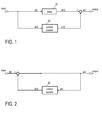
- FIG. 1 and FIG. 2 illustrate a feedforward structure and a feedback structure, respectively, for generating a compensation signal to at least partly compensate for (or ideally to eliminate) the undesired disturbing noise signal.
- the reference signal that represents the noise signal at the location of the noise source is denoted by x[n].
- the disturbing noise at the listening position where noise cancellation is desired is denoted by d[n].
- the compensation signal destructively superposing disturbing noise d[n] at the listening position is denoted by y[n]
- resulting error signal d[n]-y[n] i.e., the residual noise
- Feedforward systems may encompass a higher effectiveness than feedback arrangements, in particular due to the possibility of the broadband reduction of disturbing noises. This is a result of the fact that a signal representing the disturbing noise (i.e., reference signal x[n]) may be directly processed and used to actively counteract disturbing noise signal d[n].
- a signal representing the disturbing noise i.e., reference signal x[n]
- Such a feedforward system is illustrated in FIG. 1 in an exemplary manner.
- FIG. 1 illustrates the signal flow in a basic feedforward structure.
- Input signal x[n] e.g., the noise signal at the noise source, or a signal derived from and correlated to the noise signal
- Input signal x[n] is often referred to as reference signal x[n] for the active noise control.
- Primary path system 10 may basically impose a delay on input signal x[n], for example, due to the propagation of the noise from the noise source to that portion of the listening room (i.e., the listening position) where suppression of the disturbing noise signal should be achieved (i.e., to the desired point of silence).
- the delayed input signal is denoted by d[n] and represents the disturbing noise to be suppressed at the listening position.
- reference signal x[n] is filtered such that the filtered reference signal (denoted by y[n]), when superposed with disturbing noise signal d[n], compensates for the noise due to destructive interference in the respective portion of the listening room.
- the output signal of the feedforward structure of FIG. 1 may be regarded as error signal e[n], which is a residual signal comprising the signal components of disturbing noise signal d[n] that were not suppressed by the superposition with filtered reference signal y[n].
- the signal power of error signal e[n] may be regarded as a quality measure for the noise cancellation achieved.
- Noise suppression active noise control
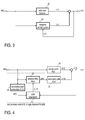
- An advantageous effect of feedback systems is that they can thereby be effectively operated even if a suitable signal (i.e., a reference signal) correlating with the disturbing noise is not available to control the active noise control arrangement. This is the case, for example, when applying ANC systems in environments that are not known a priori and in which specific information about the noise source is not available.
- FIG. 2 The principle of a feedback structure is illustrated in FIG. 2 .
- undesired acoustic noise signal d[n] is suppressed by a filtered input signal (compensation signal y[n]) provided by feedback control system 20.
- the residual signal (error signal e[n]) serves as an input for feedback loop 20.
- said arrangements are implemented for the most part so as to be adaptive, because the noise level and the spectral composition of the noise to be reduced may, for example, also be subject to chronological changes due to changing ambient conditions.
- the changes of the ambient conditions can be caused by different driving speeds (wind noises, tire noises), different load states, different engine speeds or one or more open windows.
- the transfer functions of the primary and secondary path systems may change over time.
- An unknown system may be iteratively estimated by means of an adaptive filter.
- the filter coefficients of the adaptive filter are thereby modified such that the transfer characteristic of the adaptive filter approximately matches the transfer characteristic of the unknown system.
- digital filters are used as adaptive filters (for example, finite impulse response (FIR) or infinite impulse response (IIR) filters) whose filter coefficients are modified according to a given adaptation algorithm.
- the adaptation of the filter coefficients is a recursive process that permanently optimizes the filter characteristic of the adaptive filter by minimizing an error signal that is essentially the difference between the outputs of the unknown system and the adaptive filter, wherein both are supplied with the same input signal. If a norm of the error signal approaches zero, the transfer characteristic of the adaptive filter approaches the transfer characteristic of the unknown system.
- the unknown system may thus represent the path of the noise signal from the noise source to the spot where noise suppression should be achieved (primary path).
- the noise signal is thereby "filtered" by the transfer characteristic of the signal path, which - in the case of a motor vehicle - essentially comprises the passenger compartment (primary path transfer function).
- the primary path may additionally comprise the transmission path from the actual noise source (e.g., the engine or tires) to the car body or the passenger compartment, as well as the transfer characteristics of the microphones used.
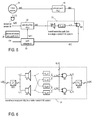
- FIG. 3 generally illustrates the estimation of unknown system 10 by means of adaptive filter 20.
- Input signal x[n] is supplied to unknown system 10 and adaptive filter 20.
- the output signal d[n] of unknown system 10and the output signal y[n] of adaptive filter 20 are destructively superposed (i.e., subtracted); the residual signal, i.e., error signal e[n], is fed back to the adaptation algorithm implemented in adaptive filter 20.
- a least mean square (LMS) algorithm may, for example, be employed for calculating modified filter coefficients such that a norm (e.g., the power) of error signal e[n] becomes minimal.
- LMS least mean square
- the LMS algorithm thereby represents an algorithm for the approximation of the solution to the least mean squares problem, as it is often used when utilizing adaptive filters, which are realized, for example, in digital signal processors.
- the algorithm is based on the method of the steepest descent (gradient descent method) and computes the gradient in a simple manner.
- the algorithm thereby operates in a time-recursive manner. That is, the algorithm is run again with each new data set, and the solution is updated. Due to its relatively low complexity and low memory requirement, the LMS algorithm is often used for adaptive filters and adaptive control, which are realized in digital signal processors. Further methods may include the following: recursive least squares, QR decomposition least squares, least squares lattices, QR decomposition lattices, gradient adaptive lattices, zero forcing, stochastic gradients, etc.
- the filtered-x LMS (FXLMS) algorithm and modifications or extensions thereof are quite often used as special embodiments of the LMS algorithm.
- the modified filtered-x LMS (MFXLMS) algorithm is an example of such a modification.
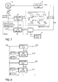
- FIG. 4 illustrates the basic structure of an ANC system employing the FXLMS algorithm in an exemplary manner. It also illustrates the basic principle of a digital feedforward active noise control system. To simplify matters, components such as amplifiers, analog-digital converters and digital-analog converters, which are required for realization, are not illustrated herein. All signals are denoted as digital signals, with time index n placed in squared brackets. Transfer functions are denoted as discrete time transfer functions in the z domain, as ANC systems are usually implemented using digital signal processors.
- Secondary path system 21, with transfer function S(z) is arranged downstream of adaptive filter 22; it represents the signal path from the loudspeaker radiating the compensation signal provided by adaptive filter 22 to the portion of the listening room where noise d[n] should be suppressed.
- the secondary path comprises the transfer characteristics of all components downstream of adaptive filter 21: for example, amplifiers, digital-analog converters, loudspeakers, acoustic transmission paths, microphones and analog-digital converters.
- estimation S*(z) (system 24) of secondary path transfer function S(z) is required.
- Primary path system 10 and secondary path system 21 are "real" systems that essentially represent the physical properties of the listening room, wherein the other transfer functions are implemented in a digital signal processor.
- Input signal x[n] represents the noise signal generated by a noise source and is therefore often referred to as "reference signal”. It is measured by an acoustic or non-acoustic sensor for further processing. Input signal x[n] is transported to a listening position via primary path system 10, which provides disturbing noise signal d[n] as an output at the listening location where noise cancellation is desired. When using a non-acoustic sensor, the input signal may be indirectly derived from the sensor signal. Reference signal x[n] is further supplied to adaptive filter 22, which provides filtered signal y[n].
- Filtered signal y[n] is supplied to secondary path system 21, which provides modified filtered signal y'[n] (i.e., the compensation signal); modified filtered signal y'[n] destructively superposes with disturbing noise signal d[n], which is the output of primary path system 10. Therefore, the adaptive filter has to impose an additional 180° phase shift on the signal path.
- the "result" of the superposition is a measurable residual signal that is used as error signal e[n] for adaptation unit 23.
- estimated model S*(z) of secondary path transfer function S(z) is required.
- Estimated secondary path transfer function S*(z) also receives input signal x[n] and provides modified reference signal x'[n] to adaptation unit 23.
- Residual error signal e[n] which may be measured by means of a microphone, is supplied to adaptation unit 23 and modified input signal x'[n], which is provided by estimated secondary path transfer function S*(z).
- Adaptation unit 23 is configured to calculate filter coefficients w k of adaptive filter transfer function W(z) from modified reference signal x'[n] (filtered x) and error signal e[k] such that a norm (e.g., the power or L 2 norm) of error signal ⁇ e[k] ⁇ becomes minimal.
- a norm e.g., the power or L 2 norm
- An LMS algorithm may be a good choice for this purpose, as already discussed above.
- Circuit blocks 22, 23 and 24 form active noise control unit 20, which may be fully implemented in a digital signal processor.
- Alternatives or modifications of the filtered-x LMS algorithm such as the filtered-e LMS algorithm are of course applicable.
- FIG. 5 illustrates a system for active noise control according to the structure of FIG. 4 .
- FIG. 5 illustrates a single-channel ANC system as an example. A generalization of the multi-channel case will be shown later with reference to FIG. 6 .
- the system of FIG. 5 illustrates noise source 31 generating the input noise signal (i.e., reference signal x[n]) for the ANC system, loudspeaker LS1 radiating filtered reference signal y[n] and microphone M1 sensing residual error signal e[n].
- the noise signal generated by noise source 31 serves as input signal x[n] to the primary path.
- Output d[n] of primary path system 10 represents noise signal d[n] to be suppressed at the listening position.
- Electrical representation x e [n] of input signal x[n] may be provided by acoustic sensor 32 (e.g., a microphone or vibration sensor that is sensitive in the audible frequency spectrum or at least in a desired spectral range thereof).
- Electrical representation x e [n] of input signal x[n] i.e., the sensor signal
- filtered signal y[n] is supplied to secondary path 21.
- the output signal of secondary path 21 is compensation signal y'[n], which is destructively interfering with noise d[n] filtered by primary path 10.
- the residual signal is measured with microphone 32, whose output signal is supplied to adaptation unit 23 as error signal e[n].
- the adaptation unit calculates optimal filter coefficients w k [n] for adaptive filter 22.
- the FXLMS algorithm may be used for this calculation, as discussed above. Since acoustic sensor 32 is capable of detecting the noise signal generated by noise source 31 in a broad frequency band of the audible spectrum, the arrangement of FIG. 5 may be used for broadband ANC applications.
- acoustic sensor 32 may be replaced by a non-acoustic sensor (e.g., a rotational speed sensor) and a signal generator to synthesize electrical representation x e [n] of reference signal x[n].
- the signal generator may use the base frequency, which is measured with the non-acoustic sensor, and higher order harmonics to synthesize reference signal x e [n].
- the non-acoustic sensor may be, for example, a revolution sensor that gives information on the rotational speed of a car engine, which may be regarded as a main noise source.
- the overall secondary path transfer function S(z) comprises the following: the transfer characteristics of loudspeaker LS1, which receives filtered reference signal y[n]; the acoustic transmission path characterized by transfer function S 11 (z); the transfer characteristics of microphone M1; and the transfer characteristics of necessary electrical components such as amplifiers, analog-digital converters, digital-analog converters, etc.
- transfer function S 11 (z) is relevant, as illustrated in FIG. 5 .
- adaptive filter 22 comprises one filter W v (z) for each channel.
- each of the W microphones receives an acoustic signal from each of the V loudspeakers, resulting in a total number of VxW acoustic transmission paths (four transmission paths in the example of FIG. 6 ).
- compensation signal y'[n] is W-dimensional vector y w '[n], each component being superposed with a corresponding disturbing noise signal component d w [n] at the respective listening position where a microphone is located.
- Superposition y w '[n]+d w [n] yields W-dimensional error signal e w [n], wherein compensation signal y w '[n] is at least approximately in phase opposition to noise signal d w [n] at the respective listening position.
- analog-digital converters and digital-analog converters are illustrated in FIG. 6 .
- FIG. 7 illustrates one exemplary multi-channel ANC system in accordance with one example of the invention.
- the example of FIG. 7 is a multi-channel enhancement of the single-channel ANC system of FIG. 4 .
- Adaptive filter 22 is thus supplied with electric reference signal x e [n], and it provides vector y v [n] of six compensation signals y 1 [n], y 2 [n], y 3 [n], y 4 [n], y 5 [n] and y 6 [n], which are supplied to the six respective loudspeakers LS1, LS2, LS3, LS4, LS5 and LS6.
- the resulting sound field gives rise to four compensation signals y' w [n] (modified by the secondary path transfer functions) at the positions of the four respective microphones M1, M2, M3 and M4.
- LMS adaptation unit 23 and the secondary path estimation is essentially the same as in the example of FIG. 4 .
- the vector of error signals e w [n] is supplied to error weighting unit 26, which usually weights (squared) error signals ew[n] to obtain weighted error signals e'w[n].
- the cost function is minimized using the aforementioned LMS algorithms implemented in LMS adaptation unit 23.
- the total error signal is calculated depending on the occupancy of the listening positions (sweet spots).
- the listening room (the target room for ANC) is the passenger compartment of the vehicle.
- the sweet spots can be generated at the driver's position (usually front left, FL) and the three passengers' positions (front right, FR, rear left, RL, and rear right, RR).
- Each of these positions (FL, FR, RL, RR) is associated with at least one microphone and is referred to as a listening position.
- the four microphones M1 (M FR ), M2 (M FL ), M3 (M RL ) and M4 (M RR ) denote the respective listening positions or sweet spots.
- the matrix g ww of weights can also be regarded as the representation of an output of an array of seat occupancy detectors.
- Seat occupancy detectors are already installed and used in many modern vehicles, e.g., to trigger an alarm signal in case a seat is occupied and the respective restraint system (safety belt) is not fastened.
- other sensors such as cameras, head tracking systems or the like may be used.
- any sensor or sensor system capable of detecting whether or not a listener occupies a listening position is regarded as an occupancy sensor.
- the sensor output can thus be used as input for the weighting, as shown, for example, in equations (3) and (4).
- the weighting may be achieved in different ways. As mentioned, multiplication with an appropriate matrix of weights is an option (see equation (4)). However, another option is to simply switch off the microphones (or deactivate the respective microphone amplifiers) for the unoccupied listening positions.
- the improved ANC system is scalable with regard to the number of error microphones used and thus with regard to the number of sweet spots.
- This scaling can be applied to noise reduction systems in general, including road noise cancellation (RNC) and engine order cancellation (EOC) systems.
- Noise reduction systems such as ANC, EOC and RNC systems have essentially the same topology (the signal processing structure) and differ only in the way electrical representation x e [n] of input signal x[n] (the reference signal) is obtained.
- an acoustic sensor such as acoustic sensor 32 (see FIG. 7 )
- non-acoustic sensors may also be used.
- accelerometers are used, which are positioned close to the vehicle's suspension.
- the use of a rotational speed sensor to measure the rotational speed of the engine is another option.
- the most that can be achieved with an ANC/EOC/RNC system is an equal damping of noise in each listening position (sweet spot). Particularly in a car, it is often the case that not all listening positions (seats) are occupied. By reducing the number of microphones and thus the number of sweet spots, the achievable damping in the listening positions that are actually occupied by a person can be improved.
- the noise level in the "deactivated" listening positions may even become higher, as compared to when all error microphones contribute to the total error signal. However, this is irrelevant in a listening position that is not occupied.
- the best performance (i.e., the highest damping of noise in a listening position) may be achieved when only a single error microphone contributes to the total error signal used for the adaptation of adaptive filter 22 (see FIG. 7 ). This single microphone is typically associated with the driver's listening position.
- FIG. 8 For the multi-channel system of FIG. 7 , some details of the filtered-x LMS algorithm are illustrated in FIG. 8 .
- (estimated) secondary path 24 can be represented by a matrix of VxW transfer functions S vw (z).
- estimated reference signal x e [n] is supplied to each filter W 1 (z), W 2 (z), ..., W v (z) of filter bank 22; these filters generate compensation signals y 1 [n], y 2 [n], ..., y v [n] as output signals supplied to loudspeakers L1, L2, ..., LV, respectively.
- VxW secondary path transfer functions Svw(z) are used to generate a corresponding number of VxW filtered (filtered-x) reference signals x vw [n], wherein filtered reference signals x 11 [n], x 12 [n], ..., x 1w [n] are used in the LMS adaptation unit associated with filter W 1 (z), filtered reference signals x 21 [n], x 22 [n], ..., x 2w [n] are used in the LMS adaptation unit associated with filter W 2 (z) and so on, as shown in FIG. 8 .
- weighted error signals e'w[n] are used in the LMS adaptation.
- reference (input) signal x[n] is obtained by estimation in feedback systems (using estimated secondary path system 24') rather than by a sensor (as is the case in feedforward systems; see FIG. 7 ).
- Estimated reference signal(s) x w [n] is/are obtained by adding residual noise ew[n] to estimated compensation signal y" w [n], which is calculated from adaptive filter output signal y v [n] using estimated secondary path transfer matrix S*(z) (system 24' in FIG.
- Signals y' w [n] superpose with the respective noise signals d w [n] at the positions of the microphones. As mentioned before, this superposition is a destructive interference that is modeled by subtractor SUB, which provides the vector of error signals e w [n].
- the error signals may be weighted using error weighting unit 26 in the same manner as described with reference to FIG. 7 .
- one reference signal x w [n] ⁇ x 1 [n], x 2 [n], ..., x w [n] ⁇ is calculated for each listening position by adding estimated compensation signals y" w [n] to error signals e w [n], which were picked up by the error microphones.
- the signal processing structure is known and is thus not discussed in further detail.
- weighted error signals e'[n] are used in the LMS adaptation (FXLMS adaptation unit 23' in FIG. 10 ) of adaptive filter bank 22. That is, error signals e[n], which correspond to unoccupied listening positions, are weighted with zero.
Abstract
A noise reduction system includes a plurality of microphones, each associated with a listening position and configured to provide an error signal that represents a residual noise signal at the respective listening position. The system further includes a plurality of loudspeakers, each being configured to receive a loudspeaker signal and to radiate a respective acoustic signal that interferes with noise at the listening positions. An adaptive multi-channel filter is supplied with a reference signal; it is configured to filter the reference signal and to provide, as filtered signals, the loudspeaker signals. The filter characteristics of the adaptive filter bank are adapted based on the error signals that are weighted with respective weight factors. The weight factors used for weighting the error signals are either one or zero, dependent on whether or not the listening position is occupied by a listener.
Description
- The present invention relates to an active noise control (ANC) system, in particular to an ANC system with a variable and adjustable number of "sweet spots".
- Disturbing noise - in contrast to a useful sound signal - is sound that is not intended to meet a certain receiver, e.g., a listener's ears. The generation process of noise and disturbing sound signals can generally be divided into three sub-processes. These are the generation of noise by a noise source, the transmission of the noise away from the noise source and the radiation of the noise signal. Suppression of noise may take place directly at the noise source, for example, by means of damping. Suppression may also be achieved by inhibiting or damping the transmission and/or radiation of noise. However, in many applications, these efforts do not yield the desired effect of reducing the noise level in a listening room below an acceptable limit. Deficiencies in noise reduction can be observed especially in the bass frequency range. Additionally or alternatively, noise control methods and systems may be employed that eliminate or at least reduce the noise radiated into a listening room by means of destructive interference, i.e., by superposing the noise signal with a compensation signal. Such systems and methods are summarized under the term active noise cancelling or active noise control (ANC).
- Although it is known that "points of silence" can be achieved in a listening room by superposing a compensation sound signal and the noise signal to be suppressed such that they destructively interfere, a reasonable technical implementation was not feasible before the development of cost-effective, high-performance digital signal processors, which may be used together with an adequate number of suitable sensors and actuators.
- Current systems for actively suppressing or reducing the noise level in a listening room (known as "active noise control" or "ANC" systems) generate a compensation sound signal with the same amplitude and frequency components as the noise signal to be suppressed, but with a phase shift of 180° with respect to the noise signal. The compensation sound signal interferes destructively with the noise signal; the noise signal is thus eliminated or damped at least at certain positions within the listening room. These positions in which a high damping of noise is achieved are often referred to as "sweet spots".
- In the case of a motor vehicle, the term noise covers, among other things, noise generated by mechanical vibrations of the engine or fans and components mechanically coupled to them, noise generated by the wind when driving and noise generated by the tires. Modern motor vehicles may comprise features such as so-called "rear seat entertainment", which presents high-fidelity audio using a plurality of loudspeakers arranged within the passenger compartment of the motor vehicle. In order to improve the quality of sound reproduction, disturbing noise has to be considered in digital audio processing. Besides this, another goal of active noise control is to facilitate conversations between people sitting in the rear seats and the front seats.
- Modern ANC systems depend on digital signal processing and digital filter techniques. A noise sensor (for example, a microphone or non-acoustic sensor) may be employed to obtain an electrical reference signal that represents the disturbing noise signal generated by a noise source. This reference signal is fed to an adaptive filter; the filtered reference signal is then supplied to an acoustic actuator (e.g., a loudspeaker) that generates a compensation sound field in phase opposition to the noise within a defined portion of the listening room (i.e., within the sweet spot), thus eliminating or at least damping the noise within this defined portion of the listening room. The residual noise signal may be measured by means of microphones in or close to each sweet spot. The resulting microphone output signals may be used as error signals, which are fed back to the adaptive filter, where the filter coefficients of the adaptive filter are modified such that the a norm (e.g., the power) of the error signals is minimized.
- A known digital signal processing method frequently used in adaptive filters is an enhancement of the known least mean squares (LMS) method for minimizing the error signal, or more precisely the power of the error signal. These enhanced LMS methods include, for example, the filtered-x LMS (FXLMS) algorithm (or modified versions thereof) and related methods such as the filtered-error LMS (FELMS) algorithm. A model that represents the acoustic transmission path from the acoustic actuator (i.e., loudspeaker) to the error signal sensor (i.e., microphone) is thereby required to apply the FXLMS (or any related) algorithm. This acoustic transmission path from the loudspeaker to the microphone is usually referred to as the "secondary path" of the ANC system, whereas the acoustic transmission path from the noise source to the microphone is usually referred to as the "primary path" of the ANC system.
- In general, ANC systems have multiple inputs (at least one error microphone in each listener position, i.e., sweet spot) and multiple outputs (a plurality of loudspeakers); they are thus referred to as "multi-channel" or "MIMO" (multiple input/multiple output) systems. In the multi-channel case, the secondary path is represented as a matrix of transfer functions, each representing the transfer behavior of the listening room from one specific loudspeaker to one specific microphone (including the characteristics of the microphone, loudspeaker, amplifier, etc.). The more channels an ANC system has, the more difficult it is to achieve a sufficient damping of noise in the sweet spots.
- A noise reduction system includes a plurality of microphones, each associated with a listening position and configured to provide an error signal that represents a residual noise signal at the respective listening position. The system further includes a plurality of loudspeakers, each being configured to receive a loudspeaker signal and to radiate a respective acoustic signal that interferes with noise at the listening positions. An adaptive multi-channel filter is supplied with a reference signal; it is configured to filter the reference signal and to provide, as filtered signals, the loudspeaker signals. The filter characteristics of the adaptive filter bank are adapted based on the error signals that are weighted with respective weight factors. The weight factors used for weighting the error signals are either one or zero, dependent on whether or not the listening position is occupied by a listener.
- Furthermore, a method for reducing noise at a plurality of listening positions includes providing a plurality of error signals by measurement, wherein each error signal represents a residual noise at one of the listening positions. A plurality of loudspeakers are used to generate an acoustic signal, which interferes with noise at the listening positions. Furthermore, the method includes filtering a reference signal by using an adaptive multi-channel filter bank that provides loudspeaker signals to the respective loudspeakers as filtered signals. The filter characteristics of the adaptive filter bank are adapted based on the error signals weighted with respective weight factors. The weight factors used for weighting the error signals are either one or zero, dependent on whether or not the listening position is occupied by a listener.
- The invention can be better understood with reference to the following description and drawings. The components in the figures are not necessarily to scale, emphasis instead being placed upon illustrating the principles of the invention. Moreover, in the figures, like reference numerals designate corresponding parts. In the drawings,
-
FIG. 1 is a simplified diagram of a feedforward structure. -
FIG. 2 is a simplified diagram of a feedback structure. -
FIG. 3 is a block diagram illustrating the basic principle of an adaptive filter. -
FIG. 4 is a block diagram illustrating a single-channel feedforward active noise control system using the filtered-x LMS (FXLMS) algorithm. -
FIG. 5 is a block diagram illustrating the single-channel ANC system ofFIG. 4 in more detail. -
FIG. 6 is a block diagram illustrating the secondary path of a two-by-two multi-channel ANC system. -
FIG. 7 is a block diagram illustrating a scalable multi-channel ANC system in accordance with one example of the invention. -
FIG. 8 is a block diagram illustrating a portion ofFIG. 7 in more detail. -
FIG. 9 is a block diagram illustrating a scalable feedback active noise control system in accordance with another example of the invention. -
FIG. 10 is a block diagram illustrating a portion ofFIG. 9 in more detail. - An exemplary active noise control (ANC) system improves music reproduction or speech intelligibility in the interior of a motor vehicle or the operation of an active headset with the suppression of undesired noises to increase the quality of the presented acoustic signals. The basic principle of such active noise control systems is thereby based on the superposition of an existing undesired disturbing signal (i.e., noise) with a compensation signal generated with the help of the active noise control system and superposed in phase opposition with the undesired disturbing noise signal, thus yielding destructive interference. In an ideal case, complete elimination of the undesired noise signal is thereby achieved.
- In a feedforward ANC system, a signal that is correlated with the undesired disturbing noise (often referred to as "reference signal") is used to generate a compensation signal that is supplied to a compensation actuator. In acoustic ANC systems, the compensation actuator is a loudspeaker. However, a feedback ANC system is present if the compensation signal is derived not from a measured reference signal correlated to the disturbing noise but rather only from the system response. That is, the reference signal is estimated from the system response in feedback ANC systems. In practice, the "system" is the overall transmission path from the noise source to the listening position where noise cancellation is desired. The "system response" to a noise input from the noise source is represented by at least one microphone output signal that is fed back to the compensation actuator (loudspeaker) via a control system, generating "anti-noise" to suppress the actual noise signal in the desired position. By means of basic block diagrams,
FIG. 1 and FIG. 2 illustrate a feedforward structure and a feedback structure, respectively, for generating a compensation signal to at least partly compensate for (or ideally to eliminate) the undesired disturbing noise signal. In these figures, the reference signal that represents the noise signal at the location of the noise source is denoted by x[n]. The disturbing noise at the listening position where noise cancellation is desired is denoted by d[n]. The compensation signal destructively superposing disturbing noise d[n] at the listening position is denoted by y[n], and resulting error signal d[n]-y[n] (i.e., the residual noise) is denoted by e[n]. - Feedforward systems may encompass a higher effectiveness than feedback arrangements, in particular due to the possibility of the broadband reduction of disturbing noises. This is a result of the fact that a signal representing the disturbing noise (i.e., reference signal x[n]) may be directly processed and used to actively counteract disturbing noise signal d[n]. Such a feedforward system is illustrated in
FIG. 1 in an exemplary manner. -
FIG. 1 illustrates the signal flow in a basic feedforward structure. Input signal x[n], e.g., the noise signal at the noise source, or a signal derived from and correlated to the noise signal, is supplied toprimary path system 10 andcontrol system 20. Input signal x[n] is often referred to as reference signal x[n] for the active noise control.Primary path system 10 may basically impose a delay on input signal x[n], for example, due to the propagation of the noise from the noise source to that portion of the listening room (i.e., the listening position) where suppression of the disturbing noise signal should be achieved (i.e., to the desired point of silence). The delayed input signal is denoted by d[n] and represents the disturbing noise to be suppressed at the listening position. Incontrol system 20, reference signal x[n] is filtered such that the filtered reference signal (denoted by y[n]), when superposed with disturbing noise signal d[n], compensates for the noise due to destructive interference in the respective portion of the listening room. As the destructive interference is not perfect, a residual noise signal remains in each of the respective portions of the listening room (i.e., in each sweet spot). The output signal of the feedforward structure ofFIG. 1 may be regarded as error signal e[n], which is a residual signal comprising the signal components of disturbing noise signal d[n] that were not suppressed by the superposition with filtered reference signal y[n]. The signal power of error signal e[n] may be regarded as a quality measure for the noise cancellation achieved. - In feedback systems, the effect of a noise disturbance on the system must initially be awaited. Noise suppression (active noise control) can only be performed when a sensor determines the effect of the disturbance. An advantageous effect of feedback systems is that they can thereby be effectively operated even if a suitable signal (i.e., a reference signal) correlating with the disturbing noise is not available to control the active noise control arrangement. This is the case, for example, when applying ANC systems in environments that are not known a priori and in which specific information about the noise source is not available.
- The principle of a feedback structure is illustrated in
FIG. 2 . According toFIG. 2 , undesired acoustic noise signal d[n] is suppressed by a filtered input signal (compensation signal y[n]) provided byfeedback control system 20. The residual signal (error signal e[n]) serves as an input forfeedback loop 20. - In a practical use of arrangements for noise suppression, said arrangements are implemented for the most part so as to be adaptive, because the noise level and the spectral composition of the noise to be reduced may, for example, also be subject to chronological changes due to changing ambient conditions. For example, when ANC systems are used in motor vehicles, the changes of the ambient conditions can be caused by different driving speeds (wind noises, tire noises), different load states, different engine speeds or one or more open windows. Moreover, the transfer functions of the primary and secondary path systems may change over time.
- An unknown system may be iteratively estimated by means of an adaptive filter. The filter coefficients of the adaptive filter are thereby modified such that the transfer characteristic of the adaptive filter approximately matches the transfer characteristic of the unknown system. In ANC applications, digital filters are used as adaptive filters (for example, finite impulse response (FIR) or infinite impulse response (IIR) filters) whose filter coefficients are modified according to a given adaptation algorithm.
- The adaptation of the filter coefficients is a recursive process that permanently optimizes the filter characteristic of the adaptive filter by minimizing an error signal that is essentially the difference between the outputs of the unknown system and the adaptive filter, wherein both are supplied with the same input signal. If a norm of the error signal approaches zero, the transfer characteristic of the adaptive filter approaches the transfer characteristic of the unknown system. In ANC applications, the unknown system may thus represent the path of the noise signal from the noise source to the spot where noise suppression should be achieved (primary path). The noise signal is thereby "filtered" by the transfer characteristic of the signal path, which - in the case of a motor vehicle - essentially comprises the passenger compartment (primary path transfer function). The primary path may additionally comprise the transmission path from the actual noise source (e.g., the engine or tires) to the car body or the passenger compartment, as well as the transfer characteristics of the microphones used.
-
FIG. 3 generally illustrates the estimation ofunknown system 10 by means ofadaptive filter 20. Input signal x[n] is supplied tounknown system 10 andadaptive filter 20. The output signal d[n] of unknown system 10and the output signal y[n] of adaptive filter 20are destructively superposed (i.e., subtracted); the residual signal, i.e., error signal e[n], is fed back to the adaptation algorithm implemented inadaptive filter 20. A least mean square (LMS) algorithm may, for example, be employed for calculating modified filter coefficients such that a norm (e.g., the power) of error signal e[n] becomes minimal. In this case, an optimal suppression of output signal d[n] ofunknown system 10 is achieved, and the transfer characteristic ofadaptive control system 20 matches the transfer characteristic ofunknown system 10. - The LMS algorithm thereby represents an algorithm for the approximation of the solution to the least mean squares problem, as it is often used when utilizing adaptive filters, which are realized, for example, in digital signal processors. The algorithm is based on the method of the steepest descent (gradient descent method) and computes the gradient in a simple manner. The algorithm thereby operates in a time-recursive manner. That is, the algorithm is run again with each new data set, and the solution is updated. Due to its relatively low complexity and low memory requirement, the LMS algorithm is often used for adaptive filters and adaptive control, which are realized in digital signal processors. Further methods may include the following: recursive least squares, QR decomposition least squares, least squares lattices, QR decomposition lattices, gradient adaptive lattices, zero forcing, stochastic gradients, etc.
- In active noise control arrangements, the filtered-x LMS (FXLMS) algorithm and modifications or extensions thereof are quite often used as special embodiments of the LMS algorithm. The modified filtered-x LMS (MFXLMS) algorithm is an example of such a modification.
-
FIG. 4 illustrates the basic structure of an ANC system employing the FXLMS algorithm in an exemplary manner. It also illustrates the basic principle of a digital feedforward active noise control system. To simplify matters, components such as amplifiers, analog-digital converters and digital-analog converters, which are required for realization, are not illustrated herein. All signals are denoted as digital signals, with time index n placed in squared brackets. Transfer functions are denoted as discrete time transfer functions in the z domain, as ANC systems are usually implemented using digital signal processors. - The model of the ANC system of
FIG. 4 comprisesprimary path system 10, with (discrete time) transfer function P(z) representing the transfer characteristics of the signal path between the noise source and the portion of the listening room where the noise should be suppressed. It further comprisesadaptive filter 22, with filter transfer function W(z) andadaptation unit 23 for calculating an optimal set of filter coefficients wk = (w0, w1, w2, ..., wL-1) foradaptive filter 22.Secondary path system 21, with transfer function S(z), is arranged downstream ofadaptive filter 22; it represents the signal path from the loudspeaker radiating the compensation signal provided byadaptive filter 22 to the portion of the listening room where noise d[n] should be suppressed. The secondary path comprises the transfer characteristics of all components downstream of adaptive filter 21: for example, amplifiers, digital-analog converters, loudspeakers, acoustic transmission paths, microphones and analog-digital converters. When using the FXLMS algorithm for the calculation of the optimal filter coefficients, estimation S*(z) (system 24) of secondary path transfer function S(z) is required.Primary path system 10 andsecondary path system 21 are "real" systems that essentially represent the physical properties of the listening room, wherein the other transfer functions are implemented in a digital signal processor. - Input signal x[n] represents the noise signal generated by a noise source and is therefore often referred to as "reference signal". It is measured by an acoustic or non-acoustic sensor for further processing. Input signal x[n] is transported to a listening position via
primary path system 10, which provides disturbing noise signal d[n] as an output at the listening location where noise cancellation is desired. When using a non-acoustic sensor, the input signal may be indirectly derived from the sensor signal. Reference signal x[n] is further supplied toadaptive filter 22, which provides filtered signal y[n]. Filtered signal y[n] is supplied tosecondary path system 21, which provides modified filtered signal y'[n] (i.e., the compensation signal); modified filtered signal y'[n] destructively superposes with disturbing noise signal d[n], which is the output ofprimary path system 10. Therefore, the adaptive filter has to impose an additional 180° phase shift on the signal path. The "result" of the superposition is a measurable residual signal that is used as error signal e[n] foradaptation unit 23. To calculate updated filter coefficients wk, estimated model S*(z) of secondary path transfer function S(z) is required. This is required to compensate for the decorrelation between filtered reference signal y[n] and compensation signal y'[n] due to the signal distortion in the secondary path. Estimated secondary path transfer function S*(z) also receives input signal x[n] and provides modified reference signal x'[n] toadaptation unit 23. - The function of the algorithm is summarized below. Due to the adaptation process, the overall transfer function W(z)·S(z) of the series connection of adaptive filter W(z) and secondary path transfer function S(z) approaches primary path transfer function P(z), wherein an additional 180° phase shift is imposed on the signal path of
adaptive filter 22; disturbing noise signal d[n] (output of primary path 10) and compensation signal y'[n] (output of the of secondary path 21) thus destructively superpose, thereby suppressing disturbing noise signal d[n] in the respective portion (sweet spot) of the listening room. - Residual error signal e[n], which may be measured by means of a microphone, is supplied to
adaptation unit 23 and modified input signal x'[n], which is provided by estimated secondary path transfer function S*(z).Adaptation unit 23 is configured to calculate filter coefficients wk of adaptive filter transfer function W(z) from modified reference signal x'[n] (filtered x) and error signal e[k] such that a norm (e.g., the power or L2 norm) of error signal ∥e[k]∥ becomes minimal. An LMS algorithm may be a good choice for this purpose, as already discussed above. Circuit blocks 22, 23 and 24 form activenoise control unit 20, which may be fully implemented in a digital signal processor. Alternatives or modifications of the filtered-x LMS algorithm such as the filtered-e LMS algorithm are of course applicable. -
FIG. 5 illustrates a system for active noise control according to the structure ofFIG. 4 . To keep things simple and clear,FIG. 5 illustrates a single-channel ANC system as an example. A generalization of the multi-channel case will be shown later with reference toFIG. 6 . In addition to the example ofFIG. 4 , which shows only the basic structure of an ANC system, the system ofFIG. 5 illustratesnoise source 31 generating the input noise signal (i.e., reference signal x[n]) for the ANC system, loudspeaker LS1 radiating filtered reference signal y[n] and microphone M1 sensing residual error signal e[n]. The noise signal generated bynoise source 31 serves as input signal x[n] to the primary path. Output d[n] ofprimary path system 10 represents noise signal d[n] to be suppressed at the listening position. Electrical representation xe[n] of input signal x[n] (i.e., the reference signal) may be provided by acoustic sensor 32 (e.g., a microphone or vibration sensor that is sensitive in the audible frequency spectrum or at least in a desired spectral range thereof). Electrical representation xe[n] of input signal x[n] (i.e., the sensor signal) is supplied toadaptive filter 22, and filtered signal y[n] is supplied tosecondary path 21. The output signal ofsecondary path 21 is compensation signal y'[n], which is destructively interfering with noise d[n] filtered byprimary path 10. The residual signal is measured withmicrophone 32, whose output signal is supplied toadaptation unit 23 as error signal e[n]. The adaptation unit calculates optimal filter coefficients wk[n] foradaptive filter 22. The FXLMS algorithm may be used for this calculation, as discussed above. Sinceacoustic sensor 32 is capable of detecting the noise signal generated bynoise source 31 in a broad frequency band of the audible spectrum, the arrangement ofFIG. 5 may be used for broadband ANC applications. - In narrowband ANC applications,
acoustic sensor 32 may be replaced by a non-acoustic sensor (e.g., a rotational speed sensor) and a signal generator to synthesize electrical representation xe[n] of reference signal x[n]. The signal generator may use the base frequency, which is measured with the non-acoustic sensor, and higher order harmonics to synthesize reference signal xe[n]. The non-acoustic sensor may be, for example, a revolution sensor that gives information on the rotational speed of a car engine, which may be regarded as a main noise source. - The overall secondary path transfer function S(z) comprises the following: the transfer characteristics of loudspeaker LS1, which receives filtered reference signal y[n]; the acoustic transmission path characterized by transfer function S11(z); the transfer characteristics of microphone M1; and the transfer characteristics of necessary electrical components such as amplifiers, analog-digital converters, digital-analog converters, etc. In the case of a single-channel ANC system, only one acoustic transmission path transfer function S11(z) is relevant, as illustrated in
FIG. 5 . In a general multi-channel ANC system that has a number of V loudspeakers LSv (v = 1, ..., V) and a number of W microphones Mw (w = 1, ..., W), the secondary path is characterized by a VxW transfer matrix of transfer functions S(z) = Svw(z). As an example, a secondary path model is illustrated inFIG. 6 for the case of V = 2 loudspeakers and W = 2 microphones. In multi-channel ANC systems,adaptive filter 22 comprises one filter Wv(z) for each channel. Adaptive filters Wv(z) provide V-dimensional filtered reference signal yv[n] (v = 1, ..., V), each signal component being supplied to the corresponding loudspeaker LSv. Each of the W microphones receives an acoustic signal from each of the V loudspeakers, resulting in a total number of VxW acoustic transmission paths (four transmission paths in the example ofFIG. 6 ). In the multi-channel case, compensation signal y'[n] is W-dimensional vector yw'[n], each component being superposed with a corresponding disturbing noise signal component dw[n] at the respective listening position where a microphone is located. Superposition yw'[n]+dw[n] yields W-dimensional error signal ew[n], wherein compensation signal yw'[n] is at least approximately in phase opposition to noise signal dw[n] at the respective listening position. Furthermore, analog-digital converters and digital-analog converters are illustrated inFIG. 6 . -
FIG. 7 illustrates one exemplary multi-channel ANC system in accordance with one example of the invention. In essence, the example ofFIG. 7 is a multi-channel enhancement of the single-channel ANC system ofFIG. 4 . Accordingly, the listening room (referred to astarget room 21 inFIG. 7 ) includes six (V = 6) loudspeakers LS1, LS2, LS3, LS4, LS5 and LS6 and four (W = 4) microphones M1, M2, M3 and M4, wherein each microphone is associated with one sweet spot. That is, four different sweet spots (listening positions) may be generated intarget room 21. - In the present example,
adaptive filter 22 is a filter bank that includes six filter transfer functions W1(z), W2(z), W3(z), W4(z), W5(z) and W6(z), briefly denoted by Wv(z), with v = {1, 2, ..., 6}.Adaptive filter 22 is thus supplied with electric reference signal xe[n], and it provides vector yv[n] of six compensation signals y1[n], y2[n], y3[n], y4[n], y5[n] and y6[n], which are supplied to the six respective loudspeakers LS1, LS2, LS3, LS4, LS5 and LS6. The resulting sound field gives rise to four compensation signals y'w[n] (modified by the secondary path transfer functions) at the positions of the four respective microphones M1, M2, M3 and M4. These four signals y'w[n] superpose with the respective noise signals dw[n] (w = 1,2, 3, 4) at the positions of microphones M1, M2, M3 and M4. As mentioned above, this superposition is a destructive interference that is modeled by the subtractor providing the vector of error signals ew[n], wherein
-
LMS adaptation unit 23 and the secondary path estimation is essentially the same as in the example ofFIG. 4 . The vector of error signals ew[n] is supplied to errorweighting unit 26, which usually weights (squared) error signals ew[n] to obtain weighted error signals e'w[n]. The total error etot[n] to be minimized by the FXLMS adaptation is also referred to as the "cost function" and is usually calculated as
in the case of four (W = 4) listening positions (sweet spots) and four corresponding error signals. The cost function is minimized using the aforementioned LMS algorithms implemented inLMS adaptation unit 23. In accordance with the present example, the total error signal is calculated depending on the occupancy of the listening positions (sweet spots). When a specific listening position is occupied by a person, the (squared) error signal ew[n]2 is weighted with a respective weight gw that equals one (gw = 1). Otherwise, when the listening position is unoccupied, the (squared) error signal ew[n]2 is weighted with a respective weight gw that equals zero (gw = 0). Accordingly, equation (2) can be rewritten as follows for the case of W = 4 listening positions:
- In a general matrix form, equation (3) can be written as follows:

wherein ew[n] is the vector of the error signals (size: 1×W), gww is a diagonal matrix of weights gw (size: WxW) and ew[n]T denotes the transposed vector of the error signals (size: W×1). As mentioned, matrix gww is a WxW diagonal matrix and can be written as gww= diag{g1, g2, ..., gw-1}. In the example ofFIG. 7 , noise reduction can be achieved at a maximum of four (W = 4) listening positions (sweet spots), anderror weighting unit 26 basically implements the weighting equation e'w[n] = gww·ew[n]. In an automotive application, the listening room (the target room for ANC) is the passenger compartment of the vehicle. The sweet spots can be generated at the driver's position (usually front left, FL) and the three passengers' positions (front right, FR, rear left, RL, and rear right, RR). Each of these positions (FL, FR, RL, RR) is associated with at least one microphone and is referred to as a listening position. In the present example, the four microphones M1 (MFR), M2 (MFL), M3 (MRL) and M4 (MRR) denote the respective listening positions or sweet spots. In case only the driver's seat is occupied (listening position FL, microphone M2), the matrix gww of weights is gww = dial {0, 1, 0, 0}. When only both front seats are occupied (listening positions FL and FR, microphones M1 and M2), the matrix gww of weights is gww= diag{1, 1, 0, 0}. When only the driver's seat and the rear right passenger seat are occupied (listening positions FL and RR, microphones M2 and M4), the matrix gww of weights is gww = dial {0, 1,0, 1}. When all seats except the front passenger seat are occupied (listening positions FL, RL and RR, microphones M2, M3 and M4), the matrix gww of weights is gww = dial {0, 1, 1, 1}. When all seats are occupied, the matrix gww of weights is gww = diag {1, 1, 1, 1}. - The matrix gww of weights can also be regarded as the representation of an output of an array of seat occupancy detectors. Seat occupancy detectors are already installed and used in many modern vehicles, e.g., to trigger an alarm signal in case a seat is occupied and the respective restraint system (safety belt) is not fastened. However, other sensors such as cameras, head tracking systems or the like may be used. In the present context, any sensor or sensor system capable of detecting whether or not a listener occupies a listening position is regarded as an occupancy sensor. Independent of the actual implementation of the occupancy sensor, the sensor output can be defined as matrix gww = diag{g1, g2, ..., gw-1}, wherein matrix elements gw are either one (listening position occupied) or zero (listening position unoccupied). The sensor output can thus be used as input for the weighting, as shown, for example, in equations (3) and (4). It should be noted that the weighting may be achieved in different ways. As mentioned, multiplication with an appropriate matrix of weights is an option (see equation (4)). However, another option is to simply switch off the microphones (or deactivate the respective microphone amplifiers) for the unoccupied listening positions.
- Regardless of the actual implementation of the weighting (multiplying by weights, (de)activating the microphones, etc.), the improved ANC system is scalable with regard to the number of error microphones used and thus with regard to the number of sweet spots. This scaling can be applied to noise reduction systems in general, including road noise cancellation (RNC) and engine order cancellation (EOC) systems. Noise reduction systems such as ANC, EOC and RNC systems have essentially the same topology (the signal processing structure) and differ only in the way electrical representation xe[n] of input signal x[n] (the reference signal) is obtained. Besides an acoustic sensor such as acoustic sensor 32 (see
FIG. 7 ), non-acoustic sensors may also be used. In an RNC system, accelerometers are used, which are positioned close to the vehicle's suspension. The use of a rotational speed sensor to measure the rotational speed of the engine is another option. - If all listening positions are occupied, the most that can be achieved with an ANC/EOC/RNC system is an equal damping of noise in each listening position (sweet spot). Particularly in a car, it is often the case that not all listening positions (seats) are occupied. By reducing the number of microphones and thus the number of sweet spots, the achievable damping in the listening positions that are actually occupied by a person can be improved. The noise level in the "deactivated" listening positions may even become higher, as compared to when all error microphones contribute to the total error signal. However, this is irrelevant in a listening position that is not occupied. The best performance (i.e., the highest damping of noise in a listening position) may be achieved when only a single error microphone contributes to the total error signal used for the adaptation of adaptive filter 22 (see
FIG. 7 ). This single microphone is typically associated with the driver's listening position. - For the multi-channel system of
FIG. 7 , some details of the filtered-x LMS algorithm are illustrated inFIG. 8 . In particular, the signal flow from estimated reference signal xe[n] to output signals yv[n] ofadaptive filter bank 22 with transfer functions Wv(z) is shown (v = 1, 2, ..., V). As mentioned above, (estimated)secondary path 24 can be represented by a matrix of VxW transfer functions Svw(z). In accordance withFIG. 8 , estimated reference signal xe[n] is supplied to each filter W1(z), W2(z), ..., Wv(z) offilter bank 22; these filters generate compensation signals y1[n], y2[n], ..., yv[n] as output signals supplied to loudspeakers L1, L2, ..., LV, respectively. The VxW secondary path transfer functions Svw(z) are used to generate a corresponding number of VxW filtered (filtered-x) reference signals xvw[n], wherein filtered reference signals x11[n], x12[n], ..., x1w[n] are used in the LMS adaptation unit associated with filter W1(z), filtered reference signals x21[n], x22[n], ..., x2w[n] are used in the LMS adaptation unit associated with filter W2(z) and so on, as shown inFIG. 8 . Besides the filtered reference signals, weighted error signals e'w[n] are used in the LMS adaptation. - The scaling of the number of actively used error microphones, as described above with reference to
FIG. 7 , is not limited to feedforward ANC systems; it can readily be used in feedback ANC systems, as illustrated inFIG. 9 . One important difference between feedforward ANC systems and feedback ANC systems is that reference (input) signal x[n] is obtained by estimation in feedback systems (using estimated secondary path system 24') rather than by a sensor (as is the case in feedforward systems; seeFIG. 7 ). Estimated reference signal(s) xw[n] is/are obtained by adding residual noise ew[n] to estimated compensation signal y"w[n], which is calculated from adaptive filter output signal yv[n] using estimated secondary path transfer matrix S*(z) (system 24' inFIG. 9 ). The remaining components of the ANC system illustrated inFIG. 9 are substantially the same as in the feedforward system ofFIG. 7 . Accordingly,adaptive filter 22 is a filter bank that includes filter transfer functions Wv(z) (where v = {1, 2, ..., V}), that is supplied with reference signal x[n] and that provides vector yv[n], which is supplied to the respective loudspeakers. The resulting sound field gives rise to compensation signals y'w[n] (modified by the secondary path transfer functions) at the positions of the respective microphones M1, M2, M3 and M4. Furthermore, estimated compensation signals y"w[n] are calculated as mentioned above. Signals y'w[n] superpose with the respective noise signals dw[n] at the positions of the microphones. As mentioned before, this superposition is a destructive interference that is modeled by subtractor SUB, which provides the vector of error signals ew[n]. The error signals may be weighted usingerror weighting unit 26 in the same manner as described with reference toFIG. 7 . - In contrast to feedforward systems, more than one reference signal is obtained; one reference signal xw[n] = {x1[n], x2[n], ..., xw[n]} is calculated for each listening position by adding estimated compensation signals y"w[n] to error signals ew[n], which were picked up by the error microphones. The detailed signal processing is illustrated in
FIG. 10 for the case of a 2x2 feedback ANC system (V = 2, W = 2). The signal processing structure is known and is thus not discussed in further detail. However, similar to the example ofFIG. 7 (which shows a feedforward ANC system), weighted error signals e'[n] are used in the LMS adaptation (FXLMS adaptation unit 23' inFIG. 10 ) ofadaptive filter bank 22. That is, error signals e[n], which correspond to unoccupied listening positions, are weighted with zero. - While various embodiments of the invention have been described, it will be apparent to those of ordinary skill in the art that many more embodiments and implementations are possible within the scope of the invention. Accordingly, the invention is not to be restricted except in light of the attached claims and their equivalents. With regard to the various functions performed by the components or structures described above (assemblies, devices, circuits, systems, etc.), the terms (including a reference to a "means") used to describe such components are intended to correspond, unless otherwise indicated, to any component or structure that performs the specified function of the described component (i.e., that is functionally equivalent), even if not structurally equivalent to the disclosed structure that performs the function in the exemplary implementations of the invention illustrated herein.
Claims (15)
- A noise reduction system comprising:a plurality of microphones, each microphone being associated with a listening position and configured to provide an error signal that represents a residual noise signal at the respective listening positions;a plurality of loudspeakers, each loudspeaker being configured to receive a loudspeaker signal and radiate a respective acoustic signal that interferes with noise at the listening positions;an adaptive multi-channel filter supplied with a reference signal, configured to filter the reference signal and configured to provide the loudspeaker signals as filtered signals,wherein the filter characteristics of the adaptive filter bank are adapted based on the error signals that are weighted with respective weight factors,
wherein the weight factors used for weighting the error signals are either one or zero, depending on whether or not the listening positions are occupied by listeners. - The noise reduction system of claim 1, wherein the filter characteristics of the adaptive filter bank are adapted such that a cost function is minimized, the cost function representing the weighted sum of the squared error signals.
- The noise reduction system of claim 1 or 2, wherein the microphones are arranged in the passenger compartment of a car and the listening positions are associated with a driver's seat and at least one passenger seat of the car.
- The noise reduction system of any of claims 1 to 3, further comprising an occupancy sensor that is configured to detect whether or not the listening positions are occupied by listeners.
- The noise reduction system of any of claims 1 to 4,
wherein one weight factor is associated with one corresponding error signal, and
wherein a weight factor of zero is accomplished by deactivating the respective microphone, setting the respective error signal to zero or multiplying the respective error signal by zero. - The noise reduction system of any of claims 1 to 5, wherein the reference signal represents the noise signal.
- The noise reduction system of claim 6, further comprising an acoustic or non-acoustic sensor configured to generate the reference signal, which is a representation of the noise signal generated by the noise source.
- The noise reduction system of any of claims 1 to 7, further comprising an error weighting unit configured to calculate the weighted error signals depending on the error signals and the weight factors.
- The noise reduction system of any of claims 1 to 7, wherein the reference signal represents the noise signal, which is picked up by a sensor.
- The noise reduction system of any of claims 1 to 7, wherein the reference signal represents the noise signal, which is estimated from the error signals and the output signals of the adaptive filter bank.
- A method for reducing noise at a plurality of listening positions, the method comprising:providing, by measurement, a plurality of error signals, each error signal representing a residual noise at one of the listening positions;using of a plurality of loudspeakers to generate an acoustic signal, which interferes with noise at the listening positions;filtering of a reference signal using an adaptive multi-channel filter bank that provides loudspeaker signals to the respective loudspeakers as filtered signals, wherein the filter characteristics of the adaptive filter bank are adapted based on the error signals weighted with respective weight factors,wherein the weight factors used for weighting the error signals are either one or zero, depending on whether or not the listening position is occupied by a listener.
- The method of claim 11, wherein the filter characteristics of the adaptive filter bank are adapted such that a cost function is minimized, the cost function representing the weighted sum of the squared error signals.
- The method of claim 11 or 12, wherein providing a plurality of error signals by measurement includes using microphones that are arranged at the listening positions and that are configured to generate signal representations of the residual noise as error signals at the respective listening positions.
- The method of any of claims 11 to 13, further comprising the use of an occupancy sensor to detect whether or not the listening positions are occupied by a listener.
- The method of claim 14, wherein the weight factor is zero if the respective listening position is unoccupied and one if the respective listening position is occupied.
Priority Applications (1)
| Application Number | Priority Date | Filing Date | Title |
|---|---|---|---|
| EP14184177.5A EP2996111A1 (en) | 2014-09-10 | 2014-09-10 | Scalable adaptive noise control system |
Applications Claiming Priority (1)
| Application Number | Priority Date | Filing Date | Title |
|---|---|---|---|
| EP14184177.5A EP2996111A1 (en) | 2014-09-10 | 2014-09-10 | Scalable adaptive noise control system |
Publications (1)
| Publication Number | Publication Date |
|---|---|
| EP2996111A1 true EP2996111A1 (en) | 2016-03-16 |
Family
ID=51518618
Family Applications (1)
| Application Number | Title | Priority Date | Filing Date |
|---|---|---|---|
| EP14184177.5A Withdrawn EP2996111A1 (en) | 2014-09-10 | 2014-09-10 | Scalable adaptive noise control system |
Country Status (1)
| Country | Link |
|---|---|
| EP (1) | EP2996111A1 (en) |
Cited By (9)
| Publication number | Priority date | Publication date | Assignee | Title |
|---|---|---|---|---|
| CN107274881A (en) * | 2016-03-31 | 2017-10-20 | 哈曼贝克自动系统股份有限公司 | Automatic Noise measarement |
| CN107600011A (en) * | 2017-08-02 | 2018-01-19 | 上海迪彼电子科技有限公司 | The active control noise reduction system and method for a kind of automobile engine noise |
| CN109427324A (en) * | 2017-08-22 | 2019-03-05 | 通用汽车环球科技运作有限责任公司 | For controlling the method and system for being originated from the noise in outside vehicle source |
| EP3528241A1 (en) * | 2018-02-20 | 2019-08-21 | Panasonic Intellectual Property Management Co., Ltd. | Noise reduction device, noise reduction system, and noise reduction control method |
| US10418021B2 (en) | 2018-02-21 | 2019-09-17 | Panasonic Intellectual Property Management Co., Ltd. | Noise reduction device, noise reduction system, and noise reduction control method |
| WO2020047293A1 (en) * | 2018-08-31 | 2020-03-05 | Bose Corporation | Systems and methods for noise-cancellation with shaping and weighting filters |
| CN111063334A (en) * | 2019-12-27 | 2020-04-24 | 博迈科海洋工程股份有限公司 | Feedforward active noise reduction method for closed space of building module |
| EP3767618A1 (en) * | 2019-07-16 | 2021-01-20 | Alpine Electronics, Inc. | Noise reduction device, vehicle, noise reduction system, and noise reduction method |
| CN113345401A (en) * | 2021-05-31 | 2021-09-03 | 锐迪科微电子(上海)有限公司 | Calibration method and device of active noise reduction system of wearable device, storage medium and terminal |
Citations (4)
| Publication number | Priority date | Publication date | Assignee | Title |
|---|---|---|---|---|
| US5426703A (en) * | 1991-06-28 | 1995-06-20 | Nissan Motor Co., Ltd. | Active noise eliminating system |
| US5485523A (en) * | 1992-03-17 | 1996-01-16 | Fuji Jukogyo Kabushiki Kaisha | Active noise reduction system for automobile compartment |
| US5689572A (en) * | 1993-12-08 | 1997-11-18 | Hitachi, Ltd. | Method of actively controlling noise, and apparatus thereof |
| US20100124337A1 (en) * | 2008-11-20 | 2010-05-20 | Harman International Industries, Incorporated | Quiet zone control system |
-
2014
- 2014-09-10 EP EP14184177.5A patent/EP2996111A1/en not_active Withdrawn
Patent Citations (4)
| Publication number | Priority date | Publication date | Assignee | Title |
|---|---|---|---|---|
| US5426703A (en) * | 1991-06-28 | 1995-06-20 | Nissan Motor Co., Ltd. | Active noise eliminating system |
| US5485523A (en) * | 1992-03-17 | 1996-01-16 | Fuji Jukogyo Kabushiki Kaisha | Active noise reduction system for automobile compartment |
| US5689572A (en) * | 1993-12-08 | 1997-11-18 | Hitachi, Ltd. | Method of actively controlling noise, and apparatus thereof |
| US20100124337A1 (en) * | 2008-11-20 | 2010-05-20 | Harman International Industries, Incorporated | Quiet zone control system |
Non-Patent Citations (1)
| Title |
|---|
| KUO S M ET AL: "ACTIVE NOISE CONTROL: A TUTORIAL REVIEW", PROCEEDINGS OF THE IEEE, IEEE. NEW YORK, US, vol. 87, no. 6, 1 June 1999 (1999-06-01), pages 943 - 973, XP011044219, ISSN: 0018-9219, DOI: 10.1109/5.763310 * |
Cited By (12)
| Publication number | Priority date | Publication date | Assignee | Title |
|---|---|---|---|---|
| CN107274881A (en) * | 2016-03-31 | 2017-10-20 | 哈曼贝克自动系统股份有限公司 | Automatic Noise measarement |
| CN107274881B (en) * | 2016-03-31 | 2024-02-06 | 哈曼贝克自动系统股份有限公司 | Automatic noise control |
| CN107600011A (en) * | 2017-08-02 | 2018-01-19 | 上海迪彼电子科技有限公司 | The active control noise reduction system and method for a kind of automobile engine noise |
| CN109427324A (en) * | 2017-08-22 | 2019-03-05 | 通用汽车环球科技运作有限责任公司 | For controlling the method and system for being originated from the noise in outside vehicle source |
| EP3528241A1 (en) * | 2018-02-20 | 2019-08-21 | Panasonic Intellectual Property Management Co., Ltd. | Noise reduction device, noise reduction system, and noise reduction control method |
| US10418021B2 (en) | 2018-02-21 | 2019-09-17 | Panasonic Intellectual Property Management Co., Ltd. | Noise reduction device, noise reduction system, and noise reduction control method |
| WO2020047293A1 (en) * | 2018-08-31 | 2020-03-05 | Bose Corporation | Systems and methods for noise-cancellation with shaping and weighting filters |
| US10741165B2 (en) | 2018-08-31 | 2020-08-11 | Bose Corporation | Systems and methods for noise-cancellation with shaping and weighting filters |
| EP3767618A1 (en) * | 2019-07-16 | 2021-01-20 | Alpine Electronics, Inc. | Noise reduction device, vehicle, noise reduction system, and noise reduction method |
| US11276385B2 (en) | 2019-07-16 | 2022-03-15 | Alpine Electronics, Inc. | Noise reduction device, vehicle, noise reduction system, and noise reduction method |
| CN111063334A (en) * | 2019-12-27 | 2020-04-24 | 博迈科海洋工程股份有限公司 | Feedforward active noise reduction method for closed space of building module |
| CN113345401A (en) * | 2021-05-31 | 2021-09-03 | 锐迪科微电子(上海)有限公司 | Calibration method and device of active noise reduction system of wearable device, storage medium and terminal |
Similar Documents
| Publication | Publication Date | Title |
|---|---|---|
| US9633645B2 (en) | Adaptive noise control system with improved robustness | |
| US10373600B2 (en) | Active noise control system | |
| EP2216774B1 (en) | Adaptive noise control system and method | |
| EP2996111A1 (en) | Scalable adaptive noise control system | |
| EP3437090B1 (en) | Adaptive modeling of secondary path in an active noise control system | |
| US8565443B2 (en) | Adaptive noise control system | |
| EP2239729B1 (en) | Quiet zone control system | |
| EP1577879B1 (en) | Active noise tuning system, use of such a noise tuning system and active noise tuning method | |
| JP7149336B2 (en) | Active noise control with feedback compensation | |
| EP3196874B1 (en) | Noise suppression device, noise suppression method, and program | |
| US11514882B2 (en) | Feedforward active noise control | |
| US11250832B2 (en) | Feedforward active noise control | |
| EP2257082A1 (en) | Background noise estimation in a loudspeaker-room-microphone system | |
| CN112805778A (en) | System and method for noise cancellation using microphone projection | |
| JPH0643881A (en) | Active noise controller |
Legal Events
| Date | Code | Title | Description |
|---|---|---|---|
| PUAI | Public reference made under article 153(3) epc to a published international application that has entered the european phase |
Free format text: ORIGINAL CODE: 0009012 |
|
| AK | Designated contracting states |
Kind code of ref document: A1 Designated state(s): AL AT BE BG CH CY CZ DE DK EE ES FI FR GB GR HR HU IE IS IT LI LT LU LV MC MK MT NL NO PL PT RO RS SE SI SK SM TR |
|
| AX | Request for extension of the european patent |
Extension state: BA ME |
|
| STAA | Information on the status of an ep patent application or granted ep patent |
Free format text: STATUS: THE APPLICATION IS DEEMED TO BE WITHDRAWN |
|
| 18D | Application deemed to be withdrawn |
Effective date: 20160917 |