EP2995923A1 - Material-odor-assaying device, assaying retainer used therein, and material-odor-testing method used with said material-odor-assaying device - Google Patents
Material-odor-assaying device, assaying retainer used therein, and material-odor-testing method used with said material-odor-assaying device Download PDFInfo
- Publication number
- EP2995923A1 EP2995923A1 EP14794667.7A EP14794667A EP2995923A1 EP 2995923 A1 EP2995923 A1 EP 2995923A1 EP 14794667 A EP14794667 A EP 14794667A EP 2995923 A1 EP2995923 A1 EP 2995923A1
- Authority
- EP
- European Patent Office
- Prior art keywords
- sample
- attachment
- holder
- pressing body
- odor
- Prior art date
- Legal status (The legal status is an assumption and is not a legal conclusion. Google has not performed a legal analysis and makes no representation as to the accuracy of the status listed.)
- Withdrawn
Links
- 238000013027 odor testing Methods 0.000 title claims abstract description 26
- 238000000034 method Methods 0.000 title claims description 8
- 238000003825 pressing Methods 0.000 claims abstract description 76
- 238000012360 testing method Methods 0.000 claims description 26
- 238000004458 analytical method Methods 0.000 claims description 11
- 239000011347 resin Substances 0.000 claims description 7
- 229920005989 resin Polymers 0.000 claims description 7
- 238000002360 preparation method Methods 0.000 claims description 5
- 238000010586 diagram Methods 0.000 description 16
- 229920001343 polytetrafluoroethylene Polymers 0.000 description 9
- 239000004810 polytetrafluoroethylene Substances 0.000 description 9
- 230000001055 chewing effect Effects 0.000 description 8
- 238000005259 measurement Methods 0.000 description 7
- 238000004154 testing of material Methods 0.000 description 6
- 235000013305 food Nutrition 0.000 description 5
- 125000000391 vinyl group Chemical group [H]C([*])=C([H])[H] 0.000 description 5
- 229920002554 vinyl polymer Polymers 0.000 description 5
- XMGQYMWWDOXHJM-JTQLQIEISA-N (+)-α-limonene Chemical compound CC(=C)[C@@H]1CCC(C)=CC1 XMGQYMWWDOXHJM-JTQLQIEISA-N 0.000 description 4
- WRMNZCZEMHIOCP-UHFFFAOYSA-N 2-phenylethanol Chemical compound OCCC1=CC=CC=C1 WRMNZCZEMHIOCP-UHFFFAOYSA-N 0.000 description 4
- GLZPCOQZEFWAFX-UHFFFAOYSA-N Geraniol Chemical compound CC(C)=CCCC(C)=CCO GLZPCOQZEFWAFX-UHFFFAOYSA-N 0.000 description 4
- 229910052782 aluminium Inorganic materials 0.000 description 4
- XAGFODPZIPBFFR-UHFFFAOYSA-N aluminium Chemical compound [Al] XAGFODPZIPBFFR-UHFFFAOYSA-N 0.000 description 4
- RRAFCDWBNXTKKO-UHFFFAOYSA-N eugenol Chemical compound COC1=CC(CC=C)=CC=C1O RRAFCDWBNXTKKO-UHFFFAOYSA-N 0.000 description 4
- CDOSHBSSFJOMGT-UHFFFAOYSA-N linalool Chemical compound CC(C)=CCCC(C)(O)C=C CDOSHBSSFJOMGT-UHFFFAOYSA-N 0.000 description 4
- 238000002470 solid-phase micro-extraction Methods 0.000 description 4
- WTEVQBCEXWBHNA-UHFFFAOYSA-N Citral Natural products CC(C)=CCCC(C)=CC=O WTEVQBCEXWBHNA-UHFFFAOYSA-N 0.000 description 3
- -1 acryl Chemical group 0.000 description 3
- 229940043350 citral Drugs 0.000 description 3
- 239000007789 gas Substances 0.000 description 3
- 238000004817 gas chromatography Methods 0.000 description 3
- WTEVQBCEXWBHNA-JXMROGBWSA-N geranial Chemical compound CC(C)=CCC\C(C)=C\C=O WTEVQBCEXWBHNA-JXMROGBWSA-N 0.000 description 3
- 229910052751 metal Inorganic materials 0.000 description 3
- 239000002184 metal Substances 0.000 description 3
- 238000013001 point bending Methods 0.000 description 3
- 239000012780 transparent material Substances 0.000 description 3
- 239000001490 (3R)-3,7-dimethylocta-1,6-dien-3-ol Substances 0.000 description 2
- KJPRLNWUNMBNBZ-QPJJXVBHSA-N (E)-cinnamaldehyde Chemical compound O=C\C=C\C1=CC=CC=C1 KJPRLNWUNMBNBZ-QPJJXVBHSA-N 0.000 description 2
- OOCCDEMITAIZTP-QPJJXVBHSA-N (E)-cinnamyl alcohol Chemical compound OC\C=C\C1=CC=CC=C1 OOCCDEMITAIZTP-QPJJXVBHSA-N 0.000 description 2
- CDOSHBSSFJOMGT-JTQLQIEISA-N (R)-linalool Natural products CC(C)=CCC[C@@](C)(O)C=C CDOSHBSSFJOMGT-JTQLQIEISA-N 0.000 description 2
- IJGRMHOSHXDMSA-UHFFFAOYSA-N Atomic nitrogen Chemical compound N#N IJGRMHOSHXDMSA-UHFFFAOYSA-N 0.000 description 2
- NPBVQXIMTZKSBA-UHFFFAOYSA-N Chavibetol Natural products COC1=CC=C(CC=C)C=C1O NPBVQXIMTZKSBA-UHFFFAOYSA-N 0.000 description 2
- 239000005770 Eugenol Substances 0.000 description 2
- 239000005792 Geraniol Substances 0.000 description 2
- GLZPCOQZEFWAFX-YFHOEESVSA-N Geraniol Natural products CC(C)=CCC\C(C)=C/CO GLZPCOQZEFWAFX-YFHOEESVSA-N 0.000 description 2
- FRLZQXRXIKQFNS-UHFFFAOYSA-N Methyl 2-octynoate Chemical compound CCCCCC#CC(=O)OC FRLZQXRXIKQFNS-UHFFFAOYSA-N 0.000 description 2
- UVMRYBDEERADNV-UHFFFAOYSA-N Pseudoeugenol Natural products COC1=CC(C(C)=C)=CC=C1O UVMRYBDEERADNV-UHFFFAOYSA-N 0.000 description 2
- AXMVYSVVTMKQSL-UHFFFAOYSA-N UNPD142122 Natural products OC1=CC=C(C=CC=O)C=C1O AXMVYSVVTMKQSL-UHFFFAOYSA-N 0.000 description 2
- OOCCDEMITAIZTP-UHFFFAOYSA-N allylic benzylic alcohol Natural products OCC=CC1=CC=CC=C1 OOCCDEMITAIZTP-UHFFFAOYSA-N 0.000 description 2
- 235000015111 chews Nutrition 0.000 description 2
- 229940117916 cinnamic aldehyde Drugs 0.000 description 2
- KJPRLNWUNMBNBZ-UHFFFAOYSA-N cinnamic aldehyde Natural products O=CC=CC1=CC=CC=C1 KJPRLNWUNMBNBZ-UHFFFAOYSA-N 0.000 description 2
- 229910001873 dinitrogen Inorganic materials 0.000 description 2
- 230000000694 effects Effects 0.000 description 2
- 229960002217 eugenol Drugs 0.000 description 2
- 239000000835 fiber Substances 0.000 description 2
- 229940113087 geraniol Drugs 0.000 description 2
- 239000011521 glass Substances 0.000 description 2
- 239000011261 inert gas Substances 0.000 description 2
- 229930007744 linalool Natural products 0.000 description 2
- 239000000463 material Substances 0.000 description 2
- 239000000203 mixture Substances 0.000 description 2
- 229940067107 phenylethyl alcohol Drugs 0.000 description 2
- 238000012545 processing Methods 0.000 description 2
- 238000010926 purge Methods 0.000 description 2
- 229920001817 Agar Polymers 0.000 description 1
- YCKRFDGAMUMZLT-UHFFFAOYSA-N Fluorine atom Chemical compound [F] YCKRFDGAMUMZLT-UHFFFAOYSA-N 0.000 description 1
- 125000003118 aryl group Chemical group 0.000 description 1
- 150000001875 compounds Chemical class 0.000 description 1
- 238000011156 evaluation Methods 0.000 description 1
- 239000000796 flavoring agent Substances 0.000 description 1
- 235000019634 flavors Nutrition 0.000 description 1
- 229910052731 fluorine Inorganic materials 0.000 description 1
- 239000011737 fluorine Substances 0.000 description 1
- 238000004128 high performance liquid chromatography Methods 0.000 description 1
- 238000012986 modification Methods 0.000 description 1
- 230000004048 modification Effects 0.000 description 1
- 210000000214 mouth Anatomy 0.000 description 1
- 210000003928 nasal cavity Anatomy 0.000 description 1
- 239000002304 perfume Substances 0.000 description 1
- 238000001184 proton transfer reaction mass spectrometry Methods 0.000 description 1
- 238000010998 test method Methods 0.000 description 1
Images



Classifications
-
- G—PHYSICS
- G01—MEASURING; TESTING
- G01N—INVESTIGATING OR ANALYSING MATERIALS BY DETERMINING THEIR CHEMICAL OR PHYSICAL PROPERTIES
- G01N30/00—Investigating or analysing materials by separation into components using adsorption, absorption or similar phenomena or using ion-exchange, e.g. chromatography or field flow fractionation
- G01N30/02—Column chromatography
- G01N30/04—Preparation or injection of sample to be analysed
- G01N30/06—Preparation
-
- G—PHYSICS
- G01—MEASURING; TESTING
- G01N—INVESTIGATING OR ANALYSING MATERIALS BY DETERMINING THEIR CHEMICAL OR PHYSICAL PROPERTIES
- G01N1/00—Sampling; Preparing specimens for investigation
- G01N1/02—Devices for withdrawing samples
- G01N1/22—Devices for withdrawing samples in the gaseous state
- G01N1/2226—Sampling from a closed space, e.g. food package, head space
-
- G—PHYSICS
- G01—MEASURING; TESTING
- G01N—INVESTIGATING OR ANALYSING MATERIALS BY DETERMINING THEIR CHEMICAL OR PHYSICAL PROPERTIES
- G01N1/00—Sampling; Preparing specimens for investigation
- G01N1/28—Preparing specimens for investigation including physical details of (bio-)chemical methods covered elsewhere, e.g. G01N33/50, C12Q
-
- G—PHYSICS
- G01—MEASURING; TESTING
- G01N—INVESTIGATING OR ANALYSING MATERIALS BY DETERMINING THEIR CHEMICAL OR PHYSICAL PROPERTIES
- G01N30/00—Investigating or analysing materials by separation into components using adsorption, absorption or similar phenomena or using ion-exchange, e.g. chromatography or field flow fractionation
- G01N30/02—Column chromatography
- G01N30/62—Detectors specially adapted therefor
- G01N30/72—Mass spectrometers
- G01N30/7206—Mass spectrometers interfaced to gas chromatograph
Definitions
- the present invention relates to a sample odor testing device for measuring the odor released from a sample such as of a food product, a sample holder used therein, and a sample odor examination method.
- chewing modeling devices with which the odor released during chewing can be measured have been disclosed (see Non-Patent Document 1).
- a strength test is carried out on a target sample within a sealed container in cylindrical form made of a transparent material such as glass or acryl, and after that, a Tenax (registered trademark) tube is connected, or a PTR-MS or the like is linked, to the inside of the sealed container so as to purge the inside with an inert gas (such as a nitrogen gas), and thus, the odor released during the imitated chewing is measured.
- an inert gas such as a nitrogen gas
- FIG. 8 is a schematic diagram showing the structure of a material testing device for carrying out a three-point bending strength test.
- one direction that is horizontal relative to the ground is the X direction
- the direction that is horizontal relative to the ground and perpendicular to the X direction is the Y direction
- the direction that is perpendicular to the X direction and the Y direction is the Z direction.
- a material testing device 101 is provided with: a device base 7; a housing 14 for supporting two threaded rods 5, 13 so as to be rotatable with the upward and downward directions (Z direction) being the rotational axis; a support base 112 provided and fixed in the center portion of the device base 7 on the upper side; a crosshead 8 that engages the threaded rods 5, 13 so as to be movable in the upward and downward directions relative to the device base 7 as the threaded rods 5, 13 rotate; a load cell 111 provided and fixed in the center portion of the crosshead 8 on the lower side; and an operation control unit 3 for controlling and processing the system.
- a motor 4 controlled through a control signal from the operation control unit 3, a belt 61 for conveying the rotational force from the motor 4 to the threaded rods 5, 13, and a gear mechanism 6 to which an interlocking pulley 62 is linked are arranged inside the device base 7.
- the motor 4 can rotate so as to rotate the two threaded rods 5, 13, thereby moving the crosshead 8 in the upward and downward directions relative to the device base 7.
- Two supports 130 in plate form that are aligned in the X direction so as to be parallel to each other are attached to the upper surface of the support base 112. Meanwhile, one plunger (pressure applying body) 120 is attached to the lower surface of the load cell 111.
- a test piece S n in plate form is placed between the supports 130 and the plunger 120 with the upper ends of the two supports 130 being the fulcrums and with the lower end of the plunger 120 being the loading point so that a load W can be applied to a predetermined portion of the test piece S n .
- Patent Document 1 Japanese Unexamined Patent Publication 2012-251901
- Non-Patent Document 1 " Measurement of Flavor Released During Chewing of a Food Product," Chemistry and Biology, Vol. 47, No. 9, 2009, pgs. 624-629
- the present inventors examined the sample odor testing device so as to find a way to improve the device so that after one sample S 1 has been measured, a next sample S 2 can be immediately measured.
- the inventors decided to use a sample bag (bag body) made of a transparent material in place of the sealed container in cylindrical form made of a transparent material such as glass or acryl.
- a sample bag bag body
- the sample bag was disposable, the removal of the odor absorbed within the sealed container was no longer troublesome.
- a test retainer that was provided with a pressing body having a plunger (pressing portion) and a threaded portion (attachment portion) and a sample holder having a sample mounting base and a threaded portion (attachment portion) was fabricated, and the sample mounting base, the plunger and a sample S n were arranged within the sample bag.
- a test retainer that was provided with a pressing body having a plunger (pressing portion) and a threaded portion (attachment portion) and a sample holder having a sample mounting base and a threaded portion (attachment portion) was fabricated, and the sample mounting base, the plunger and a sample S n were arranged within the sample bag.
- the present inventors found that it is effective to use a sample bag (bag body) and to arrange a plunger (pressing portion), a sample mounting base and a sample S n within the sample bag.
- the inventors also found that it is preferable for the form of the sample mounting base to be a disc having a diameter that is 1.5 times greater than the diameter of the sample, and furthermore for the disc to be provided with a trench having a depth that is 15% of the height of the sample on the upper surface in order to avoid moving the sample S n when being pressed.
- the plunger it is preferable for the plunger to have the same height as the sample.
- the sample odor testing device is provided with: a first attachment unit to which a sample holder is to be attached; and a second attachment unit to which a pressing body is to be attached, wherein the above-described sample holder has a sample mounting base on which a sample is to be mounted and a holder attachment portion for the attachment to the above-described first attachment unit, and the above-described pressing body has a pressing portion for applying a load to a sample and a pressing body attachment portion for the attachment to the above-described second attachment unit, and is characterized by further including a bag body in which a first hole through which the above-described holder attachment portion penetrates and a second hole through which the above-described pressing body attachment portion penetrates are created, wherein the above-described pressing body, the above-described sample mounting base and a sample are arranged within the above-described bag body.
- a bag body is used so that a pressing portion, a sample mounting base and a sample are arranged within the bag body, and therefore, in the case where one sample has been measured and then a next sample is to be measured, it is easy to remove or replace the sample holder and the pressing portion, which increases the measurement efficiency.
- the above-described bag body may be made of a transparent resin
- the above-described sample mounting base and the above-described pressing body may be made of a resin
- a fluorine resin can be cited as an example of a transparent resin used for the bag body.
- polytetrafluoroethylene (PTFE) can be cited as an example of a resin used for the sample mounting base and the pressing body.
- the above-described invention may be provided with an XY stage, and the above-described sample holder may be attached to the above-described first attachment unit with the above-described XY stage in between.
- the form of the above-described sample mounting base may be a disc having a diameter that is 1.3 times or more greater and 1.7 times or less greater than the diameter of the sample, a trench having a depth of 10% or greater and 20% or smaller of the height of the sample may be created on the upper surface of the disc, and the above-described pressing portion may have a height that is 0.5 times or more greater and 1.5 times or less greater than the height of the sample.
- test retainer is to be used in a sample odor testing device that is provided with: a first attachment unit to which a sample holder is to be attached; and a second attachment unit to which a pressing body is to be attached, and the test retainer is characterized by including: a sample holder having a sample mounting base on which a sample is to be mounted and a holder attachment portion for the attachment to the above-described first attachment unit; a pressing body having a pressing portion for applying a load to a sample and a pressing body attachment portion for the attachment to the above-described second attachment unit; and a bag body in which a first hole through which the above-described holder attachment portion penetrates and a second hole through which the above-described pressing body attachment portion penetrates are created.
- the sample odor examination method is a sample odor examination method to be used for a sample odor testing device that is provided with: a first attachment unit to which a sample holder is to be attached; and a second attachment unit to which a pressing body is to be attached, wherein the above-described sample holder has a sample mounting base on which a sample is to be mounted and a holder attachment portion for the attachment to the above-described first attachment unit, and the above-described pressing body has a pressing portion for applying a load to a sample and a pressing body attachment portion for the attachment to the above-described second attachment unit, and the sample odor examination method is characterized by including: a preparation step of preparing a bag body in which a first hole through which the above-described holder attachment portion penetrates and a second hole through which the above-described pressing body attachment portion penetrates are created; an arrangement step of arranging the above-described pressing portion, the above-described sample mounting base and a sample within the above-described bag
- the " analyzing device” may be any device with which the odor released from a sample can be measured, and gas chromatography (GC), a gas chromatography mass spectrometer (GCMS), high performance liquid chromatography (HPLC) and an odor identifying device (FF) can be cited as examples of the analyzing device.
- GC gas chromatography
- GCMS gas chromatography mass spectrometer
- HPLC high performance liquid chromatography
- FF odor identifying device
- FIG. 1 is a schematic diagram showing the structure of the sample odor testing device according to an embodiment of the present invention.
- FIG. 2 is a cross-sectional diagram showing an enlargement of A in FIG. 1
- FIG. 3 is a cross-sectional diagram showing an enlargement of B in FIG. 1 .
- the sample S n in this embodiment has a cylindrical form with a diameter of 40 mm and a height of 15 mm. A case where the odor released from the sample S n is measured with a GCMS using solid phase micro extraction (SPME) is described below.
- SPME solid phase micro extraction
- the sample odor testing device 1 is provided with: a device base 7; a housing 14 for supporting two threaded rods 5, 13 so as to be rotatable with a rotational axis being in the upward and downward directions (Z direction); a first attachment unit 12 formed in the center portion on the upper surface of the device base 7; a crosshead 8 that engages the threaded rods 5, 13 so as to be able to move in the upward and downward directions relative to the device base 7 when the threaded rods 5, 13 rotate; a load cell (second attachment unit) 11 provided in and fixed to the center portion of the lower surface of the crosshead 8; a test retainer 50 having a sample holder 31, an XY stage 33, a pressing body 21, an adaptor body 22, and a two litter sample bag (bag body) 40; and an operation control unit 3 for controlling and processing the system.
- a threaded hole 11a (having a diameter of 6 mm, for example) is created upwardly from the lower surface in the center portion of the load cell 11, which makes the adaptor body 22 removable using a screw mechanism.
- FIG. 4 is a plan diagram showing the sample holder 31 and the XY stage 33.
- FIG. 5 is an exploded cross-sectional diagram showing the same as FIG. 2 .
- the XY stage 33 has an X stage 33c in rectangular parallelepiped form (60 mm x 40 mm x 8 mm, for example) made of aluminum (metal) to be fixed to the first attachment unit 12 and a Y stage 33a in rectangular parallelepiped form (40 mm x 60 mm x 22 mm, for example) made of aluminum (metal) that is arranged above the X stage.
- a handle 33d is formed so as to protrude from the X stage 33c in the Y direction so that the user can rotate the handle 33d in order to move the upper portion of the X stage 33c in the X direction relative to the lower portion of the X stage 33c.
- a handle 33b is formed so as to protrude in the X direction from the Y stage 33a so that the user can rotate the handle 33b in order to move the upper portion of the Y stage 33a in the Y direction relative to the lower portion of the Y stage 33a.
- one threaded hole 33e (having a diameter of 6 mm, for example) is created downwardly from the upper surface of the Y stage 33a in the center portion, which makes the sample holder 31 removable using a screw mechanism.
- the sample holder 31 has a sample mounting base 31a in disc form made of PTFE (having a diameter of 60 mm and a height of 10 mm, for example) and a threaded portion 31b made of PTFE (holder attachment portion having a diameter of 6 mm, for example), which protrudes downwardly from the lower surface of the sample mounting base 31a in the center portion.
- a trench 31c in cylindrical form which has a depth that is 15% of the height of the sample S n and a diameter that is greater than the diameter of the sample S n by 2 mm (as an example, a diameter of 42 mm and a depth of 3 mm) , is created in the upper surface of the sample mounting base 31a.
- the sample S n having a diameter of 40 mm and a height of 15 mm can be mounted within the trench 31c.
- a handle hole 31d in cylindrical form is created laterally on the side of the sample mounting base 31a.
- a threaded portion 31b is inserted through a washer 32 in annular form (having a thickness of 2 mm, for example) made of PTFE, inserted through the first hole 42 of the sample bag 40 and inserted through an O-ring 34 made of rubber, and after that inserted into a threaded hole 33e.
- the user inserts a handle 60 in rod form into the handle hole 31d and rotates the threaded portion 31b using the handle 60 in order to secure the threaded portion 31b in the threaded hole 33.
- FIG. 6 is an exploded cross-sectional diagram showing the same as FIG. 3 .
- An adaptor body 22 has a main body portion 22a in cylindrical form (having a diameter of 22 mm and a height of 15 mm, for example) made of aluminum (metal) and a threaded portion 22b (having a diameter of 6 mm, for example) made of aluminum that protrudes upward from the upper surface of the main body portion 22a in the center portion.
- one threaded hole 22c (having a diameter of 6 mm, for example) is created upwardly from the lower surface of the main body portion 22a in the center portion, which makes the pressing body 21 removable using a screw mechanism.
- a handle hole 22d in cylindrical form is created laterally on the side of the main body portion 22a.
- the threaded portion 22b can be inserted into the threaded hole 11a of the load cell 11.
- the user can insert the handle 60 in rod form into the handle hole 22b and rotate the threaded portion 22b using the handle 60 in order to secure the threaded portion 22b in the screw hole 11a.
- the pressing body 21 has a main body portion 21a in cylindrical form (having a diameter of 22 mm and a height of 5 mm, for example) made of PTFE, a plunger (pressing portion) in cylindrical form (having a diameter of 8 mm and a height of 20 mm, for example) made of PTFE that protrudes downward from the lower surface of the main body portion 21a in the center portion, and a threaded portion 21c made of PTFE (pressing body attachment portion having a diameter of 6 mm, for example) that protrudes upward from the upper surface of the main body portion 21a in the center portion.
- a handle hole 21d in cylindrical form is created laterally on the side of the main body portion 21a.
- the threaded portion 21c is inserted through a washer 23 in annular form (having a thickness of 2 mm, for example) made of PTFE, inserted through the second hole 41 of the sample bag 40, and inserted through an O-ring 24 made of rubber, and after that inserted into the threaded hole 22c.
- the user can insert a handle 60 in rod form into the handle hole 21d and rotate the threaded portion 21c using the handle 60 in order to secure the threaded portion 21c in the threaded hole 22c.
- FIG. 7 is a perspective diagram showing a sample bag 40 and a clip 49.
- the sample bag 40 is a bag body made of transparent vinyl (three sides of a first vinyl sheet of 215 mm ⁇ 250 mm and three sides of a second vinyl sheet of 215 mm ⁇ 250 mm are pasted together to create an opening 43, for example), where a first hole 42 in circular form (having a diameter of 6 mm, for example) through which the threaded portion (holder attachment portion) 31b is to penetrate is created in the center portion of the first vinyl sheet and a second hole 41 in circular form (having a diameter of 6 mm, for example) through which the threaded portion (pressing body attachment portion) 21c is to penetrate is created in the center portion of the second vinyl sheet.
- a tube 44 for linking the bag body to the GCMS is provided at the bottom of the sample bag 40.
- the clip 49 is to close the opening 43.
- the sample odor examination method includes: a preparation step (A) of preparing a sample S n , a sample bag 40 and a test retainer 50; an arrangement step (B) of arranging the sample S n , the sample bag 40 and the test retainer 50 in predetermined locations; an examination step (C) of moving the pressing body 21 in the upward and downward directions relative to the sample S n ; and an analysis step (D) of introducing the gas that exists within the sample bag 40 into the GCMS.
- a user prepares a sample S 1 , a sample bag 40 and a test retainer 50.
- the form of the sample mounting base 31a in the test retainer 50 is a disc having a diameter that is 1.3 times or more greater and 1.7 times or less greater than the diameter of the sample S 1 , and a trench 31c having a depth that is 10% or greater and 20% or smaller than the height of the sample S 1 is created on the upper surface of the disc.
- the disc it is preferable for the disc to have a diameter that is 1.5 times greater than the diameter of the sample S 1 and for a trench 31c having a depth that is 15% of the height of the sample S 1 to be created on the upper surface of the disc.
- the plunger 21b has a height that is 0.5 times greater or more and 1.5 times greater or less than the height of the sample S 1 , and in particular, it is preferable for the plunger 21b to have the same height as the sample S 1 .
- the user arranges the sample S 1 , the sample bag 40 and the test retainer 50 in predetermined locations. Concretely, the user first attaches the XY stage 33 to the first attachment portion 12, and at the same time attaches the adaptor body 22 to the load cell (second attachment portion) 11. Next, the sample S 1 is mounted within the trench 31c, the threaded portion 31b is inserted through the washer 32, and this assembly is contained within the sample bag 40 through the opening 43 of the sample bag 40 . After that, the threaded portion 31b is inserted through the first hole 42 of the sample bag 40 and through an O-ring so as to be secured in the screw hole 33e.
- the threaded portion 21c is inserted through the washer 23, and the pressing body 21 is contained within the sample bag 40 through the opening 43 of the sample bag 40.
- the threaded portion 21c is inserted through the second hole 41 of the sample bag 40 and through an O-ring so as to be secured in the screw hole 22c.
- the opening 43 of the sample bag 40 is closed using the clip 49.
- the plunger 21 is arranged 5 mm to 10 mm above the sample S n of which the location is adjusted using the XY stage 33.
- the user moves the pressing body 21 in the upward and downward directions relative to the sample S 1 .
- the user starts measurement by inputting a measurement start signal into the operation control unit 3 in the state where the locations of the pressing body 21 and the sample S 1 have been adjusted through the arrangement step (B).
- a control signal is emitted from the operation control unit 3 and the pressing body 21 descends at a constant speed (100 mm/min, for example) for 0.1 minutes.
- the pressing body 21 ascends at a constant speed for 0.05 minutes and then descends at a constant speed for 0.05 minutes, which is repeated a number of times (four times, for example) .
- the plunger 21b chews the sample S 1 .
- an odor is released from the sample S 1 and stays within the sample bag 40.
- the user links the tube 44 of the sample bag 40 to the GCMS and purges the inside of the sample bag 40 with an inert gas (nitrogen gas, for example), and thus introduces the gas that exists within the sample bag 40 into the GCMS.
- an inert gas nitrogen gas, for example
- the user After the completion of the analysis step (D), the user removes the threaded portion 31b from the screw hole 33e, and at the same time removes the threaded portion 21c from the screw hole 22c.
- a new sample bag 40, a new sample mounting base 31a, a new washer 32, a new pressing body 21 and a new washer 23 are prepared, or a new sample bag 40 is prepared and the sample mounting base 31a, the washers 23, 32 and the pressing body 21 are cleaned. As a result, it is easy to remove or replace the sample holder 31 and the pressing body 21, which increases the measurement efficiency.
- a cylinder having a diameter of 40 mm and a height of 15 mm is made of 100 ml of 2.5 wt% agar gel to which 3 ⁇ l of a perfume mixture (D-Limonene, Linalool, Methyl 2-octynoate, Citral (mixture of two isomer components), Geraniol, Phenylethyl Alcohol, Cinnamic aldehyde, Eugenol, Cinnamic alcohol) is added. Then, the sample S 1 is wrapped and stored at 35°C.
- a perfume mixture D-Limonene, Linalool, Methyl 2-octynoate, Citral (mixture of two isomer components), Geraniol, Phenylethyl Alcohol, Cinnamic aldehyde, Eugenol, Cinnamic alcohol
- the preparation step (A), the arrangement step (B) and the analysis step (D) were carried out on the sample S 1 . That is to say, the state in the arrangement step (B) was maintained for five minutes, and after that, the components were collected by the SPME fibers for five minutes. After that, the sample S 1 was taken out from the sample bag 40, and the sample S 1 was again wrapped and stored at 35°C.
- the arrangement step (B), the examination step (C) and the analysis step (D) were carried out on the same sample S 1 .
- the plunger 21b descended at 100 mm/min for 0.1 minutes. After that, the plunger 21b ascended at 100 mm/min for 0.05 minutes and descended at 100 mm/min for 0.05 minutes, which was repeated four times. After the completion of the examination step (C), the state was maintained for five minutes and the components were collected by the SPME fibers for five minutes.
- the peak area values D 2 are greater than the peak area values D 1 , and thus, the release of each aroma component could be quantitatively confirmed.
- the present invention can be applied to sample odor testing devices for measuring the odor released from a sample such as of a food product.
Landscapes
- Health & Medical Sciences (AREA)
- Life Sciences & Earth Sciences (AREA)
- General Health & Medical Sciences (AREA)
- Physics & Mathematics (AREA)
- Chemical & Material Sciences (AREA)
- Analytical Chemistry (AREA)
- Biochemistry (AREA)
- General Physics & Mathematics (AREA)
- Immunology (AREA)
- Pathology (AREA)
- Biomedical Technology (AREA)
- Molecular Biology (AREA)
- Engineering & Computer Science (AREA)
- Sampling And Sample Adjustment (AREA)
Abstract
Description
- The present invention relates to a sample odor testing device for measuring the odor released from a sample such as of a food product, a sample holder used therein, and a sample odor examination method.
- When a person chews a food product, aromatic components are released from the food product within the oral cavity and ride on the flow of exhaled air so as to reach the inside of the nasal cavity, which stimulates the olfactory senses. In addition, the chewing characteristics depend on the person.
- Upon the understanding of such chewing characteristics, chewing modeling devices (sample odor testing devices) with which the odor released during chewing can be measured have been disclosed (see Non-Patent Document 1). In these chewing modeling devices, a strength test is carried out on a target sample within a sealed container in cylindrical form made of a transparent material such as glass or acryl, and after that, a Tenax (registered trademark) tube is connected, or a PTR-MS or the like is linked, to the inside of the sealed container so as to purge the inside with an inert gas (such as a nitrogen gas), and thus, the odor released during the imitated chewing is measured.
- Meanwhile, material testing devices for carrying out a three-point bending strength test have been disclosed as testing devices (see Patent Document 1).
FIG. 8 is a schematic diagram showing the structure of a material testing device for carrying out a three-point bending strength test. Here, one direction that is horizontal relative to the ground is the X direction, the direction that is horizontal relative to the ground and perpendicular to the X direction is the Y direction, and the direction that is perpendicular to the X direction and the Y direction is the Z direction. - A
material testing device 101 is provided with: adevice base 7; ahousing 14 for supporting two threadedrods support base 112 provided and fixed in the center portion of thedevice base 7 on the upper side; acrosshead 8 that engages the threadedrods device base 7 as the threadedrods load cell 111 provided and fixed in the center portion of thecrosshead 8 on the lower side; and anoperation control unit 3 for controlling and processing the system. - A
motor 4 controlled through a control signal from theoperation control unit 3, abelt 61 for conveying the rotational force from themotor 4 to the threadedrods gear mechanism 6 to which aninterlocking pulley 62 is linked are arranged inside thedevice base 7. As a result, themotor 4 can rotate so as to rotate the two threadedrods crosshead 8 in the upward and downward directions relative to thedevice base 7. - Two supports 130 in plate form that are aligned in the X direction so as to be parallel to each other are attached to the upper surface of the
support base 112. Meanwhile, one plunger (pressure applying body) 120 is attached to the lower surface of theload cell 111. A test piece Sn in plate form is placed between thesupports 130 and theplunger 120 with the upper ends of the two supports 130 being the fulcrums and with the lower end of theplunger 120 being the loading point so that a load W can be applied to a predetermined portion of the test piece Sn. - By using this
material testing device 101, the moment when the test piece Sn is cracked and broken is detected. - Patent Document 1:
Japanese Unexamined Patent Publication 2012-251901 - Non-Patent Document 1: "Measurement of Flavor Released During Chewing of a Food Product," Chemistry and Biology, Vol. 47, No. 9, 2009, pgs. 624-629
- When one sample S1 has been measured and a next sample S2 is to be measured in the above-described chewing modeling device, it is troublesome to remove the broken sample S1 and wash off the odor absorbed within the sealed container, and thus, such a problem arises that the efficiency in the measurement work is poor.
- In order to solve the above-described problem, the present inventors examined the sample odor testing device so as to find a way to improve the device so that after one sample S1 has been measured, a next sample S2 can be immediately measured. Thus, the inventors decided to use a sample bag (bag body) made of a transparent material in place of the sealed container in cylindrical form made of a transparent material such as glass or acryl. As a result, since the sample bag was disposable, the removal of the odor absorbed within the sealed container was no longer troublesome. Then, a test retainer that was provided with a pressing body having a plunger (pressing portion) and a threaded portion (attachment portion) and a sample holder having a sample mounting base and a threaded portion (attachment portion) was fabricated, and the sample mounting base, the plunger and a sample Sn were arranged within the sample bag. As a result, it became possible to clean only the plunger and the sample mounting base or to easily replace the plunger and the sample mounting base with new ones.
- In view of the above-described facts, the present inventors found that it is effective to use a sample bag (bag body) and to arrange a plunger (pressing portion), a sample mounting base and a sample Sn within the sample bag. The inventors also found that it is preferable for the form of the sample mounting base to be a disc having a diameter that is 1.5 times greater than the diameter of the sample, and furthermore for the disc to be provided with a trench having a depth that is 15% of the height of the sample on the upper surface in order to avoid moving the sample Sn when being pressed. Furthermore, the inventors found that it is preferable for the plunger to have the same height as the sample.
- That is to say, the sample odor testing device according to the present invention is provided with: a first attachment unit to which a sample holder is to be attached; and a second attachment unit to which a pressing body is to be attached, wherein the above-described sample holder has a sample mounting base on which a sample is to be mounted and a holder attachment portion for the attachment to the above-described first attachment unit, and the above-described pressing body has a pressing portion for applying a load to a sample and a pressing body attachment portion for the attachment to the above-described second attachment unit, and is characterized by further including a bag body in which a first hole through which the above-described holder attachment portion penetrates and a second hole through which the above-described pressing body attachment portion penetrates are created, wherein the above-described pressing body, the above-described sample mounting base and a sample are arranged within the above-described bag body.
- In the sample odor testing device according to the present invention, a bag body is used so that a pressing portion, a sample mounting base and a sample are arranged within the bag body, and therefore, in the case where one sample has been measured and then a next sample is to be measured, it is easy to remove or replace the sample holder and the pressing portion, which increases the measurement efficiency.
- In addition, in the above-described invention, the above-described bag body may be made of a transparent resin, and the above-described sample mounting base and the above-described pressing body may be made of a resin.
- Here, a fluorine resin can be cited as an example of a transparent resin used for the bag body. In addition, polytetrafluoroethylene (PTFE) can be cited as an example of a resin used for the sample mounting base and the pressing body.
- Furthermore, the above-described invention may be provided with an XY stage, and the above-described sample holder may be attached to the above-described first attachment unit with the above-described XY stage in between.
- Moreover, in the above-described invention, the form of the above-described sample mounting base may be a disc having a diameter that is 1.3 times or more greater and 1.7 times or less greater than the diameter of the sample, a trench having a depth of 10% or greater and 20% or smaller of the height of the sample may be created on the upper surface of the disc, and the above-described pressing portion may have a height that is 0.5 times or more greater and 1.5 times or less greater than the height of the sample.
- In this sample odor testing device, a trench is created, and therefore, the material can be prevented from moving when the material is pressed.
- In addition, the test retainer according to the present invention is to be used in a sample odor testing device that is provided with: a first attachment unit to which a sample holder is to be attached; and a second attachment unit to which a pressing body is to be attached, and the test retainer is characterized by including: a sample holder having a sample mounting base on which a sample is to be mounted and a holder attachment portion for the attachment to the above-described first attachment unit; a pressing body having a pressing portion for applying a load to a sample and a pressing body attachment portion for the attachment to the above-described second attachment unit; and a bag body in which a first hole through which the above-described holder attachment portion penetrates and a second hole through which the above-described pressing body attachment portion penetrates are created.
- Furthermore, the sample odor examination method according to the present invention is a sample odor examination method to be used for a sample odor testing device that is provided with: a first attachment unit to which a sample holder is to be attached; and a second attachment unit to which a pressing body is to be attached, wherein the above-described sample holder has a sample mounting base on which a sample is to be mounted and a holder attachment portion for the attachment to the above-described first attachment unit, and the above-described pressing body has a pressing portion for applying a load to a sample and a pressing body attachment portion for the attachment to the above-described second attachment unit, and the sample odor examination method is characterized by including: a preparation step of preparing a bag body in which a first hole through which the above-described holder attachment portion penetrates and a second hole through which the above-described pressing body attachment portion penetrates are created; an arrangement step of arranging the above-described pressing portion, the above-described sample mounting base and a sample within the above-described bag body so that the above-described sample holder is attached to the above-described first attachment unit, and at the same time, the above-described pressing body is attached to the above-described second attachment unit; an examination step of moving the above-described sample holder and/or the above-described pressing body; and an analysis step for introducing a gas that exists within the above-described bag body into an analyzing device.
- Here, the " analyzing device " may be any device with which the odor released from a sample can be measured, and gas chromatography (GC), a gas chromatography mass spectrometer (GCMS), high performance liquid chromatography (HPLC) and an odor identifying device (FF) can be cited as examples of the analyzing device.
-
-
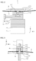
FIG. 1 is a schematic diagram showing the structure of the sample odor testing device according to an embodiment of the present invention; -
FIG. 2 is a cross-sectional diagram showing an enlargement of A inFIG. 1 ; -
FIG. 3 is a cross-sectional diagram showing an enlargement of B inFIG. 1 ; -
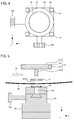
FIG. 4 is a plan diagram showing the sample holder and the XY stage; -
FIG. 5 is an exploded cross-sectional diagram showing the same asFIG. 2 ; -
FIG. 6 is an exploded cross-sectional diagram showing the same asFIG. 3 ; -
FIG. 7 is a perspective diagram showing a sample bag and a clip; and -
FIG. 8 is a schematic diagram showing the structure of the material testing device for carrying out a three-point bending strength test. - In the following, an embodiment of the present invention is described in reference to the drawings. Here, the present invention is not limited to the below-described embodiment, and it is needless to say that various modifications are included as long as the gist of the present invention is not deviated from.
-
FIG. 1 is a schematic diagram showing the structure of the sample odor testing device according to an embodiment of the present invention.FIG. 2 is a cross-sectional diagram showing an enlargement of A inFIG. 1 , andFIG. 3 is a cross-sectional diagram showing an enlargement of B inFIG. 1 . Here, the same symbols are attached to the same components as in thematerial testing device 101. The sample Sn in this embodiment has a cylindrical form with a diameter of 40 mm and a height of 15 mm. A case where the odor released from the sample Sn is measured with a GCMS using solid phase micro extraction (SPME) is described below. - The sample
odor testing device 1 is provided with: adevice base 7; ahousing 14 for supporting two threadedrods first attachment unit 12 formed in the center portion on the upper surface of thedevice base 7; acrosshead 8 that engages the threadedrods device base 7 when the threadedrods crosshead 8; atest retainer 50 having asample holder 31, anXY stage 33, apressing body 21, anadaptor body 22, and a two litter sample bag (bag body) 40; and anoperation control unit 3 for controlling and processing the system. - It is possible to fix the
XY stage 33 to the upper surface of thefirst attachment unit 12 using fourscrews 12a. In addition, a threadedhole 11a (having a diameter of 6 mm, for example) is created upwardly from the lower surface in the center portion of theload cell 11, which makes theadaptor body 22 removable using a screw mechanism. -
FIG. 4 is a plan diagram showing thesample holder 31 and theXY stage 33.FIG. 5 is an exploded cross-sectional diagram showing the same asFIG. 2 . TheXY stage 33 has anX stage 33c in rectangular parallelepiped form (60 mm x 40 mm x 8 mm, for example) made of aluminum (metal) to be fixed to thefirst attachment unit 12 and aY stage 33a in rectangular parallelepiped form (40 mm x 60 mm x 22 mm, for example) made of aluminum (metal) that is arranged above the X stage. Ahandle 33d is formed so as to protrude from theX stage 33c in the Y direction so that the user can rotate thehandle 33d in order to move the upper portion of theX stage 33c in the X direction relative to the lower portion of theX stage 33c. In addition, ahandle 33b is formed so as to protrude in the X direction from theY stage 33a so that the user can rotate thehandle 33b in order to move the upper portion of theY stage 33a in the Y direction relative to the lower portion of theY stage 33a. Thus, one threadedhole 33e (having a diameter of 6 mm, for example) is created downwardly from the upper surface of theY stage 33a in the center portion, which makes thesample holder 31 removable using a screw mechanism. - The
sample holder 31 has asample mounting base 31a in disc form made of PTFE (having a diameter of 60 mm and a height of 10 mm, for example) and a threadedportion 31b made of PTFE (holder attachment portion having a diameter of 6 mm, for example), which protrudes downwardly from the lower surface of thesample mounting base 31a in the center portion. In addition, atrench 31c in cylindrical form, which has a depth that is 15% of the height of the sample Sn and a diameter that is greater than the diameter of the sample Sn by 2 mm (as an example, a diameter of 42 mm and a depth of 3 mm) , is created in the upper surface of thesample mounting base 31a. As a result, the sample Sn having a diameter of 40 mm and a height of 15 mm can be mounted within thetrench 31c. - In addition, a
handle hole 31d in cylindrical form is created laterally on the side of thesample mounting base 31a. - In this
sample holder 31, a threadedportion 31b is inserted through awasher 32 in annular form (having a thickness of 2 mm, for example) made of PTFE, inserted through thefirst hole 42 of thesample bag 40 and inserted through an O-ring 34 made of rubber, and after that inserted into a threadedhole 33e. At this time, the user inserts ahandle 60 in rod form into thehandle hole 31d and rotates the threadedportion 31b using thehandle 60 in order to secure the threadedportion 31b in the threadedhole 33. - Next,
FIG. 6 is an exploded cross-sectional diagram showing the same asFIG. 3 . Anadaptor body 22 has amain body portion 22a in cylindrical form (having a diameter of 22 mm and a height of 15 mm, for example) made of aluminum (metal) and a threadedportion 22b (having a diameter of 6 mm, for example) made of aluminum that protrudes upward from the upper surface of themain body portion 22a in the center portion. In addition, one threadedhole 22c (having a diameter of 6 mm, for example) is created upwardly from the lower surface of themain body portion 22a in the center portion, which makes thepressing body 21 removable using a screw mechanism. - In addition, a
handle hole 22d in cylindrical form is created laterally on the side of themain body portion 22a. - In the
adaptor body 22, the threadedportion 22b can be inserted into the threadedhole 11a of theload cell 11. At this time, the user can insert thehandle 60 in rod form into thehandle hole 22b and rotate the threadedportion 22b using thehandle 60 in order to secure the threadedportion 22b in thescrew hole 11a. - The
pressing body 21 has amain body portion 21a in cylindrical form (having a diameter of 22 mm and a height of 5 mm, for example) made of PTFE, a plunger (pressing portion) in cylindrical form (having a diameter of 8 mm and a height of 20 mm, for example) made of PTFE that protrudes downward from the lower surface of themain body portion 21a in the center portion, and a threadedportion 21c made of PTFE (pressing body attachment portion having a diameter of 6 mm, for example) that protrudes upward from the upper surface of themain body portion 21a in the center portion. - In addition, a
handle hole 21d in cylindrical form is created laterally on the side of themain body portion 21a. - In the
pressing body 21, the threadedportion 21c is inserted through awasher 23 in annular form (having a thickness of 2 mm, for example) made of PTFE, inserted through thesecond hole 41 of thesample bag 40, and inserted through an O-ring 24 made of rubber, and after that inserted into the threadedhole 22c. At this time, the user can insert ahandle 60 in rod form into thehandle hole 21d and rotate the threadedportion 21c using thehandle 60 in order to secure the threadedportion 21c in the threadedhole 22c. - Next,
FIG. 7 is a perspective diagram showing asample bag 40 and aclip 49. Thesample bag 40 is a bag body made of transparent vinyl (three sides of a first vinyl sheet of 215 mm × 250 mm and three sides of a second vinyl sheet of 215 mm × 250 mm are pasted together to create anopening 43, for example), where afirst hole 42 in circular form (having a diameter of 6 mm, for example) through which the threaded portion (holder attachment portion) 31b is to penetrate is created in the center portion of the first vinyl sheet and asecond hole 41 in circular form (having a diameter of 6 mm, for example) through which the threaded portion (pressing body attachment portion) 21c is to penetrate is created in the center portion of the second vinyl sheet. In addition, atube 44 for linking the bag body to the GCMS is provided at the bottom of thesample bag 40. Here, theclip 49 is to close theopening 43. - Here, the sample odor examination method for measuring the odor released from a sample Sn using the sample
odor testing device 1 according to the embodiment of the present invention is described. The sample odor examination method includes: a preparation step (A) of preparing a sample Sn, asample bag 40 and atest retainer 50; an arrangement step (B) of arranging the sample Sn, thesample bag 40 and thetest retainer 50 in predetermined locations; an examination step (C) of moving thepressing body 21 in the upward and downward directions relative to the sample Sn; and an analysis step (D) of introducing the gas that exists within thesample bag 40 into the GCMS. - A user prepares a sample S1, a
sample bag 40 and atest retainer 50. At this time, it is preferable to prepare such atest retainer 50 where the form of thesample mounting base 31a in thetest retainer 50 is a disc having a diameter that is 1.3 times or more greater and 1.7 times or less greater than the diameter of the sample S1, and atrench 31c having a depth that is 10% or greater and 20% or smaller than the height of the sample S1 is created on the upper surface of the disc. Particularly, it is preferable for the disc to have a diameter that is 1.5 times greater than the diameter of the sample S1 and for atrench 31c having a depth that is 15% of the height of the sample S1 to be created on the upper surface of the disc. Furthermore, it is preferable to prepare such atest retainer 50 where theplunger 21b has a height that is 0.5 times greater or more and 1.5 times greater or less than the height of the sample S1, and in particular, it is preferable for theplunger 21b to have the same height as the sample S1. - The user arranges the sample S1, the
sample bag 40 and thetest retainer 50 in predetermined locations. Concretely, the user first attaches theXY stage 33 to thefirst attachment portion 12, and at the same time attaches theadaptor body 22 to the load cell (second attachment portion) 11. Next, the sample S1 is mounted within thetrench 31c, the threadedportion 31b is inserted through thewasher 32, and this assembly is contained within thesample bag 40 through theopening 43 of thesample bag 40 . After that, the threadedportion 31b is inserted through thefirst hole 42 of thesample bag 40 and through an O-ring so as to be secured in thescrew hole 33e. Next, the threadedportion 21c is inserted through thewasher 23, and thepressing body 21 is contained within thesample bag 40 through theopening 43 of thesample bag 40. After that, the threadedportion 21c is inserted through thesecond hole 41 of thesample bag 40 and through an O-ring so as to be secured in thescrew hole 22c. Next, theopening 43 of thesample bag 40 is closed using theclip 49. Finally, theplunger 21 is arranged 5 mm to 10 mm above the sample Sn of which the location is adjusted using theXY stage 33. - The user moves the
pressing body 21 in the upward and downward directions relative to the sample S1. The user starts measurement by inputting a measurement start signal into theoperation control unit 3 in the state where the locations of thepressing body 21 and the sample S1 have been adjusted through the arrangement step (B). When the measurement start signal is inputted, a control signal is emitted from theoperation control unit 3 and thepressing body 21 descends at a constant speed (100 mm/min, for example) for 0.1 minutes. After that, thepressing body 21 ascends at a constant speed for 0.05 minutes and then descends at a constant speed for 0.05 minutes, which is repeated a number of times (four times, for example) . As a result, theplunger 21b chews the sample S1. At this time, an odor is released from the sample S1 and stays within thesample bag 40. - After the completion of the examination step (C), the user links the
tube 44 of thesample bag 40 to the GCMS and purges the inside of thesample bag 40 with an inert gas (nitrogen gas, for example), and thus introduces the gas that exists within thesample bag 40 into the GCMS. As a result, the odor released from the sample S1 is measured. - After the completion of the analysis step (D), the user removes the threaded
portion 31b from thescrew hole 33e, and at the same time removes the threadedportion 21c from thescrew hole 22c. After that, in the case where a next sample S2 is to be measured, anew sample bag 40, a newsample mounting base 31a, anew washer 32, a newpressing body 21 and anew washer 23 are prepared, or anew sample bag 40 is prepared and thesample mounting base 31a, thewashers pressing body 21 are cleaned. As a result, it is easy to remove or replace thesample holder 31 and thepressing body 21, which increases the measurement efficiency. -
- (1) Though the sample
odor testing device 1 has such a structure as to be provided with adevice base 7, ahousing 14, afirst attachment portion 12 and acrosshead 8 in the above description, any structure is possible as long as the sample holder and the pressing body can move in the upward and downward directions. - (2) Though the sample
odor testing device 1 has such a structure that thepressing body 21 has aplunger 21b with a diameter of 8 mm and a height of 20 mm in the above description, a structure is possible where a plunger in cylindrical form has a different size, and a pressing body having a number of plungers in columnar form of which the sizes are different may be prepared so that an appropriate plunger can be selected depending on the sample. - In the following, the present invention is described in further detail using examples; however, the present invention is not limited to the below-described examples.
- As a sample S1, a cylinder having a diameter of 40 mm and a height of 15 mm is made of 100 ml of 2.5 wt% agar gel to which 3 µl of a perfume mixture (D-Limonene, Linalool, Methyl 2-octynoate, Citral (mixture of two isomer components), Geraniol, Phenylethyl Alcohol, Cinnamic aldehyde, Eugenol, Cinnamic alcohol) is added. Then, the sample S1 is wrapped and stored at 35°C.
- As for the aroma analysis before breaking the sample S1 (before testing), the preparation step (A), the arrangement step (B) and the analysis step (D) were carried out on the sample S1. That is to say, the state in the arrangement step (B) was maintained for five minutes, and after that, the components were collected by the SPME fibers for five minutes. After that, the sample S1 was taken out from the
sample bag 40, and the sample S1 was again wrapped and stored at 35°C. - As for the aroma analysis after breaking the sample S1 (after testing), the arrangement step (B), the examination step (C) and the analysis step (D) were carried out on the same sample S1. In the examination step (C), the
plunger 21b descended at 100 mm/min for 0.1 minutes. After that, theplunger 21b ascended at 100 mm/min for 0.05 minutes and descended at 100 mm/min for 0.05 minutes, which was repeated four times. After the completion of the examination step (C), the state was maintained for five minutes and the components were collected by the SPME fibers for five minutes. - For each aroma component, the peak area value D1 from the aroma analysis before breaking the sample (before testing) and the peak area value D2 from the aroma analysis after breaking the sample (after testing) were found, and the ratio of increase was calculated using formula (1). The results are shown in Table 1.

[Table 1] Name of Compound Before Testing After Testing Ratio of Increase (%) D-Limonene 13449 186879 1290 Linalool 889782 1233643 39 Methyl 2-octynoate 288159 868265 201 Citral 177751 123346 59 Citral 299028 169816 71 Geraniol 585424 849740 45 Phenylethyl Alcohol 50987 64309 26 Cinnamic aldehyde 153774 241180 57 Eugenol 72003 117110 63 Cinnamic alcohol 1540 3424 122 - As described above in the present example, the peak area values D2 are greater than the peak area values D1, and thus, the release of each aroma component could be quantitatively confirmed.
- The present invention can be applied to sample odor testing devices for measuring the odor released from a sample such as of a food product.
-
- 1
- Sample odor testing device
- 11
- Load cell (second attachment portion)
- 12
- First attachment portion
- 21
- Pressing body
- 21b
- Plunger (pressing portion)
- 21c
- Threaded portion (pressing body attachment portion)
- 31
- Sample holder
- 31a
- Sample mounting base
- 31b
- Threaded portion (holder attachment portion)
- 40
- Sample bag (bag body)
- 41
- Second hole
- 42
- First hole
Claims (6)
- A sample odor testing device, comprising:a first attachment unit to which a sample holder is to be attached; anda second attachment unit to which a pressing body is to be attached, whereinsaid sample holder has a sample mounting base on which a sample is to be mounted and a holder attachment portion for the attachment to said first attachment unit, andsaid pressing body has a pressing portion for applying a load to a sample and a pressing body attachment portion for the attachment to said second attachment unit, characterized by further comprising a bag body in which a first hole through which said holder attachment portion penetrates and a second hole through which said pressing body attachment portion penetrates are created, whereinsaid pressing body, said sample mounting base and a sample are arranged within said bag body.
- The sample odor testing device according to Claim 1, characterized in that
said bag body is made of a transparent resin, and
said sample mounting base and said pressing body are made of a resin. - The sample odor testing device according to Claim 1 or 2, characterized by further comprising an XY stage, wherein
said sample holder can be attached to said first attachment unit with said XY stage in between. - The sample odor testing device according to any of Claims 1 through 3, characterized in that
the form of said sample mounting base is a disc having a diameter that is 1.3 times or more greater and 1.7 times or less greater than the diameter of the sample, and a trench having a depth that is 10% or greater and 20% or smaller of the height of the sample is created on the upper surface of the disc, and
said pressing portion has a height that is 0.5 times or more greater and 1.5 times or less greater than the height of the sample. - A test retainer to be used in a sample odor testing device, comprising:a first attachment unit to which a sample holder is to be attached; anda second attachment unit to which a pressing body is to be attached, characterized by comprising:a sample holder having a sample mounting base on which a sample is to be mounted and a holder attachment portion for the attachment to said first attachment unit;a pressing body having a pressing portion for applying a load to a sample and a pressing body attachment portion for the attachment to said second attachment unit; anda bag body in which a first hole through which said holder attachment portion penetrates and a second hole through which said pressing body attachment portion penetrates are created.
- A sample odor examination method to be used for a sample odor testing device, comprising:a first attachment unit to which a sample holder is to be attached; anda second attachment unit to which a pressing body is to be attached, whereinsaid sample holder has a sample mounting base on which a sample is to be mounted and a holder attachment portion for the attachment to said first attachment unit, andsaid pressing body has a pressing portion for applying a load to a sample and a pressing body attachment portion for the attachment to said second attachment unit, characterized by comprising:a preparation step of preparing a bag body in which a first hole through which said holder attachment portion penetrates and a second hole through which said pressing body attachment portion penetrates are created;an arrangement step of arranging said pressing portion, said sample mounting base and a sample within said bag body so that said sample holder is attached to said first attachment unit, and at the same time, said pressing body is attached to said second attachment unit;an examination step of moving said sample holder and/or said pressing body; andan analysis step for introducing a gas that exists within said bag body into an analyzing device.
Applications Claiming Priority (2)
| Application Number | Priority Date | Filing Date | Title |
|---|---|---|---|
| JP2013099875 | 2013-05-10 | ||
| PCT/JP2014/058796 WO2014181600A1 (en) | 2013-05-10 | 2014-03-27 | Material-odor-assaying device, assaying retainer used therein, and material-odor-testing method used with said material-odor-assaying device |
Publications (2)
| Publication Number | Publication Date |
|---|---|
| EP2995923A1 true EP2995923A1 (en) | 2016-03-16 |
| EP2995923A4 EP2995923A4 (en) | 2017-01-04 |
Family
ID=51867086
Family Applications (1)
| Application Number | Title | Priority Date | Filing Date |
|---|---|---|---|
| EP14794667.7A Withdrawn EP2995923A4 (en) | 2013-05-10 | 2014-03-27 | Material-odor-assaying device, assaying retainer used therein, and material-odor-testing method used with said material-odor-assaying device |
Country Status (5)
| Country | Link |
|---|---|
| US (1) | US20160123935A1 (en) |
| EP (1) | EP2995923A4 (en) |
| JP (1) | JPWO2014181600A1 (en) |
| CN (1) | CN105229440A (en) |
| WO (1) | WO2014181600A1 (en) |
Families Citing this family (1)
| Publication number | Priority date | Publication date | Assignee | Title |
|---|---|---|---|---|
| US20230248297A1 (en) * | 2020-04-24 | 2023-08-10 | The General Hospital Corporation | Systems and methods for administering a smell test for sars coronaviruses and covid-19 |
Family Cites Families (12)
| Publication number | Priority date | Publication date | Assignee | Title |
|---|---|---|---|---|
| SE8704963D0 (en) * | 1987-12-14 | 1987-12-14 | Leo Ab | DEVICE |
| JPH03229133A (en) * | 1990-02-02 | 1991-10-11 | Sumitomo Metal Ind Ltd | Method for evaluating and testing ceramics |
| JP3356683B2 (en) * | 1998-04-04 | 2002-12-16 | 東京エレクトロン株式会社 | Probe device |
| DE10020617A1 (en) * | 2000-04-27 | 2001-10-31 | Haarmann & Reimer Gmbh | Chewing apparatus |
| JP4775706B2 (en) * | 2006-03-06 | 2011-09-21 | 独立行政法人物質・材料研究機構 | Environmental resistance characteristic evaluation tester with pressure chamber and test method using the same |
| JP5062590B2 (en) * | 2008-01-10 | 2012-10-31 | 学校法人日本医科大学 | Mastication simulator |
| CN101441158A (en) * | 2008-12-04 | 2009-05-27 | 四川大学 | Chaw simulation circulation load application machine for dentistry |
| FR2962246B1 (en) * | 2010-07-01 | 2012-07-13 | Ecole Nationale Veterinaire Agroalimentaire Et De L Alimentation Nantes Atlantique | ARTIFICIAL MOUTH SIMULATING THE MASTICATION AND METHOD OF ANALYZING THE COMPOUNDS ORIGINATING IN SENSORY PERCEPTION, ESPECIALLY AROMAS, IMPLEMENTING SUCH AN ARTIFICIAL MOUTH |
| CN201804000U (en) * | 2010-09-25 | 2011-04-20 | 浙江吉利汽车研究院有限公司 | Novel odor evaluating and testing device |
| CN202066848U (en) * | 2011-03-28 | 2011-12-07 | 浙江豪情汽车制造有限公司 | Odor evaluation test bottle |
| JP2012251901A (en) | 2011-06-03 | 2012-12-20 | Shimadzu Corp | Material testing device |
| JP5888913B2 (en) * | 2011-09-20 | 2016-03-22 | 国立研究開発法人農業・食品産業技術総合研究機構 | Simple evaluation method for solid foods that are easy to eat by crushing with the tongue |
-
2014
- 2014-03-27 CN CN201480026683.6A patent/CN105229440A/en active Pending
- 2014-03-27 JP JP2015515814A patent/JPWO2014181600A1/en active Pending
- 2014-03-27 EP EP14794667.7A patent/EP2995923A4/en not_active Withdrawn
- 2014-03-27 US US14/889,923 patent/US20160123935A1/en not_active Abandoned
- 2014-03-27 WO PCT/JP2014/058796 patent/WO2014181600A1/en not_active Ceased
Also Published As
| Publication number | Publication date |
|---|---|
| EP2995923A4 (en) | 2017-01-04 |
| WO2014181600A1 (en) | 2014-11-13 |
| JPWO2014181600A1 (en) | 2017-02-23 |
| US20160123935A1 (en) | 2016-05-05 |
| CN105229440A (en) | 2016-01-06 |
Similar Documents
| Publication | Publication Date | Title |
|---|---|---|
| US20180364269A1 (en) | Device for automatic sampling | |
| Cassel et al. | Experiments and modeling of the Cymbopogon winterianus essential oil extraction by steam distillation | |
| Kristenson et al. | Miniaturized automated matrix solid-phase dispersion extraction of pesticides in fruit followed by gas chromatographic–mass spectrometric analysis | |
| EP1975625A3 (en) | Sample analyzer, sample analyzing method, and computer program product | |
| CN113433205B (en) | Imaging quality analysis system and analysis method using imaging quality analysis | |
| CA2311692A1 (en) | Apparatus for analyzing a volatile composition of matter releasably bonded to a pliable porous substrate and process for using said apparatus | |
| EP3245496B1 (en) | Surface extraction interface | |
| JP2013527462A (en) | Method for preparing a sample for chromatographic separation method and device for performing sample preparation | |
| US20240369460A1 (en) | Isolation and analysis of terpenes | |
| EP2995923A1 (en) | Material-odor-assaying device, assaying retainer used therein, and material-odor-testing method used with said material-odor-assaying device | |
| CN108918747A (en) | The remaining method of pesticide in Filter head type Solid Phase Extraction combination GC-QTOF/MS rapid screening and quantitative determination tobacco | |
| WO2001086283A3 (en) | Apparatus and method for multiple channel high throughput purification | |
| CN118392804B (en) | A micro-spectrophotometer and detection method thereof | |
| CN109142570A (en) | A kind of the cigarette extraction of flavor component and content assaying method in quick-fried pearl | |
| WO2021137803A1 (en) | A reactive cartridge carrying system | |
| US5087424A (en) | Apparatus for mechanical processing of a sample and a member of such an apparatus | |
| JP2016133436A (en) | Material odor test device, and material odor inspection method using the same | |
| CN104502509B (en) | A kind of method measuring phenyl three (trimethylsiloxane group) silane in Food Contact silastic material | |
| Karl et al. | Gas chromatography‐isotope ratio mass spectrometry measurements of some carboxylic esters from different apple varieties | |
| JP2022028061A (en) | Organic component extraction method | |
| KR101085194B1 (en) | Extraction Method of Volatile Compounds Using Polydimethylsiloxane Discs on Upper Layers of Samples | |
| CN216525433U (en) | Spectral analysis sample surface positioning device | |
| JP2651626B2 (en) | Determination of organosilicon compounds in air | |
| D’Silva et al. | Analysis of polybrominated diphenyl ethers in foodstuffs-extension of an extraction method for PCDD/Fs and PCBs to incorporate PBDEs | |
| CN1886643B (en) | Minimum content analysis method |
Legal Events
| Date | Code | Title | Description |
|---|---|---|---|
| PUAI | Public reference made under article 153(3) epc to a published international application that has entered the european phase |
Free format text: ORIGINAL CODE: 0009012 |
|
| 17P | Request for examination filed |
Effective date: 20151113 |
|
| AK | Designated contracting states |
Kind code of ref document: A1 Designated state(s): AL AT BE BG CH CY CZ DE DK EE ES FI FR GB GR HR HU IE IS IT LI LT LU LV MC MK MT NL NO PL PT RO RS SE SI SK SM TR |
|
| AX | Request for extension of the european patent |
Extension state: BA ME |
|
| DAX | Request for extension of the european patent (deleted) | ||
| A4 | Supplementary search report drawn up and despatched |
Effective date: 20161201 |
|
| RIC1 | Information provided on ipc code assigned before grant |
Ipc: G01N 1/00 20060101AFI20161125BHEP Ipc: G01N 30/04 20060101ALI20161125BHEP Ipc: G01N 1/22 20060101ALI20161125BHEP Ipc: G01N 30/72 20060101ALI20161125BHEP |
|
| STAA | Information on the status of an ep patent application or granted ep patent |
Free format text: STATUS: THE APPLICATION HAS BEEN WITHDRAWN |
|
| 18W | Application withdrawn |
Effective date: 20170628 |