EP2995720A1 - Vertical pneumatic fender - Google Patents
Vertical pneumatic fender Download PDFInfo
- Publication number
- EP2995720A1 EP2995720A1 EP14793982.1A EP14793982A EP2995720A1 EP 2995720 A1 EP2995720 A1 EP 2995720A1 EP 14793982 A EP14793982 A EP 14793982A EP 2995720 A1 EP2995720 A1 EP 2995720A1
- Authority
- EP
- European Patent Office
- Prior art keywords
- fender
- layers
- body portion
- intermediate rubber
- reinforcing layers
- Prior art date
- Legal status (The legal status is an assumption and is not a legal conclusion. Google has not performed a legal analysis and makes no representation as to the accuracy of the status listed.)
- Granted
Links
Images



Classifications
-
- B—PERFORMING OPERATIONS; TRANSPORTING
- B63—SHIPS OR OTHER WATERBORNE VESSELS; RELATED EQUIPMENT
- B63B—SHIPS OR OTHER WATERBORNE VESSELS; EQUIPMENT FOR SHIPPING
- B63B59/00—Hull protection specially adapted for vessels; Cleaning devices specially adapted for vessels
- B63B59/02—Fenders integral with waterborne vessels or specially adapted therefor, e.g. fenders forming part of the hull or incorporated in the hull; Rubbing-strakes
-
- E—FIXED CONSTRUCTIONS
- E02—HYDRAULIC ENGINEERING; FOUNDATIONS; SOIL SHIFTING
- E02B—HYDRAULIC ENGINEERING
- E02B17/00—Artificial islands mounted on piles or like supports, e.g. platforms on raisable legs or offshore constructions; Construction methods therefor
- E02B17/0017—Means for protecting offshore constructions
- E02B17/003—Fenders
-
- E—FIXED CONSTRUCTIONS
- E02—HYDRAULIC ENGINEERING; FOUNDATIONS; SOIL SHIFTING
- E02B—HYDRAULIC ENGINEERING
- E02B3/00—Engineering works in connection with control or use of streams, rivers, coasts, or other marine sites; Sealings or joints for engineering works in general
- E02B3/20—Equipment for shipping on coasts, in harbours or on other fixed marine structures, e.g. bollards
- E02B3/26—Fenders
-
- B—PERFORMING OPERATIONS; TRANSPORTING
- B63—SHIPS OR OTHER WATERBORNE VESSELS; RELATED EQUIPMENT
- B63B—SHIPS OR OTHER WATERBORNE VESSELS; EQUIPMENT FOR SHIPPING
- B63B59/00—Hull protection specially adapted for vessels; Cleaning devices specially adapted for vessels
- B63B59/02—Fenders integral with waterborne vessels or specially adapted therefor, e.g. fenders forming part of the hull or incorporated in the hull; Rubbing-strakes
- B63B2059/025—Fenders integral with waterborne vessels or specially adapted therefor, e.g. fenders forming part of the hull or incorporated in the hull; Rubbing-strakes pneumatic, e.g. inflatable
-
- Y—GENERAL TAGGING OF NEW TECHNOLOGICAL DEVELOPMENTS; GENERAL TAGGING OF CROSS-SECTIONAL TECHNOLOGIES SPANNING OVER SEVERAL SECTIONS OF THE IPC; TECHNICAL SUBJECTS COVERED BY FORMER USPC CROSS-REFERENCE ART COLLECTIONS [XRACs] AND DIGESTS
- Y02—TECHNOLOGIES OR APPLICATIONS FOR MITIGATION OR ADAPTATION AGAINST CLIMATE CHANGE
- Y02A—TECHNOLOGIES FOR ADAPTATION TO CLIMATE CHANGE
- Y02A30/00—Adapting or protecting infrastructure or their operation
- Y02A30/30—Adapting or protecting infrastructure or their operation in transportation, e.g. on roads, waterways or railways
Definitions
- the present invention relates to a vertical pneumatic fender, and more specifically to a vertical pneumatic fender that is capable of responding to sudden increases in berthing impact energy.
- Pneumatic fenders normally have a cylindrical-shaped body portion with bowl-shaped mirror-sections provided at both ends, and the body portion has a layered configuration with a plurality of reinforcing layers between inner rubber layer and outer rubber layer.
- the reinforcing layers are cord layers formed by arranging a plurality of cords in parallel, and the cords are disposed at a predetermined cord angle with respect to the axial direction of the cylinder.
- the cords of adjacently layered upper and lower reinforcing layers are disposed so as to intersect one another.
- the cord angle is set to roughly an angle of repose (54° to 55°) in a neutral state, with the result that there is relatively little change in the size (i.e., length and outer diameter) of the body portion even when the interior of the pneumatic fender is inflated to specified internal pressure.
- a safety valve opens, venting air within the internal space to the outside. If the safety valve remains open during this process, an excessive amount of air may be vented to the outside, causing the fender to sink due to insufficient buoyancy in the worst-case scenario. Conversely, if the fender is compressed too rapidly compared to the speed at which air is vented to the outside, the internal pressure of the fender will suddenly increase, potentially causing the fender to burst in the worst-case scenario. There is therefore a demand for a vertical pneumatic fender that is capable of responding to sudden increases in berthing impact energy.
- Patent Document 1 Japanese Unexamined Patent Application Publication No. H11-117261A
- An object of the present invention is to provide a vertical pneumatic fender that is capable of responding to sudden increases in berthing impact energy.
- a vertical pneumatic fender is a vertical pneumatic fender provided with hemispherical portions at both ends of a cylindrical body portion, the body portion being constituted by a plurality of reinforcing layers layered between an inner rubber layer and an outer rubber layer, the reinforcing layers being cord layers formed from a multiplicity of cords arranged in parallel, cords in adjacently layered upper and lower reinforcing layers being disposed so as to intersect one another at a predetermined cord angle with respect to the cylinder axial direction, a bob being connected to the lower hemispherical portion, and ballast water being contained within an internal space of the fender, wherein the fender is characterized in that intermediate rubber layers are interposed between the reinforcing layers, the cord angle is set to from 15° to 45° both inclusive in a neutral state, and an air injection device for injecting additional air is connected to the internal space.
- intermediate rubber layers in an unexpanded neutral state are interposed between the reinforcing layers, and the cords of adjacently layered upper and lower reinforcing layers are disposed intersecting each other at cord angles of from 15° to 45° both inclusive with respect to the cylinder axial direction; thus, when additional air is injected into the fender in a neutral state via the air injection device, the cord angles increase to a stable angle of repose.
- each of the intermediate rubber layers deforms in shear, with the result that the cord angle increases smoothly up to roughly the angle of repose.
- the body portion expands in diameter and the internal space rapidly increases in volume, yielding a rapid and dramatic improvement in energy-absorbing capability.
- the air injection device can be, for example, a built-in power source operated or non-electrically operated air injection cylinder.
- An air injection cylinder of this sort enables rapid injection of air into the internal space of the fender without the need for an external power source, reliably allowing for dramatic improvement in the energy absorption of the fender even during power outages and other emergency situations.
- the thickness of the intermediate rubber layer in a neutral state is, for example, from 1 mm to 5 mm both inclusive.
- An intermediate rubber layer thickness of less than 1 mm thick will impede the smooth increase of the cord angle to roughly the angle of repose, and thus making it difficult for the body portion to increase in diameter. Meanwhile, an intermediate rubber layer thickness in excess of 5 mm will cause the fender to be excessively heavy.
- a 100% modulus of from 0.5 MPa to 5.0 MPa both inclusive for the rubber forming the intermediate rubber layer will allow for the stable expansion of the body portion to a sufficient diameter. If the 100% modulus of the rubber forming the intermediate rubber layer is less than 0.5 MPa, the body portion will take time to contract and reduce in diameter, and may not return to its original diameter. Conversely, if the 100% modulus exceeds 5.0 MPa, the shear force of the intermediate rubber layer during expansion will increase, impeding deformation and making it difficult for the body portion to sufficiently increase in diameter.
- a safety valve 10 is provided in the fitting 9 of the upper hemispherical portion 3, and a pressure sensor 13 is provided in or near the fitting 9.
- the safety valve 10 opens when the internal pressure of the fender 1 exceeds a preset maximum pressure, venting air a within the internal space to the exterior and reducing the internal pressure.
- the pressure sensor 13 detects the internal pressure of the fender 1.
- ballast water W and the bob 11 apply a vertical downward force to the fender 1, and the balance between this vertical downward force and the buoyancy of the fender 1 keeps the fender 1 in an upright position with the hemispherical portions 3 on both ends disposed above and below.
- Each of the reinforcing layers 5 is a cord layer formed from a plurality of cords 6a (6b) arranged in parallel.
- the cords 6a, 6b of adjacent layered reinforcing layers 5 intersect, and are disposed with a predetermined cord angle A with respect to the cylinder axial direction (cylinder center line CL) of the body portion 2.
- the reinforcing layer 5a of the inner peripheral side first layer, the reinforcing layer 5c of the third layer, and the reinforcing layer 5e of the fifth layer have a cord angle A in the same direction.
- the outer diameter of the cords 6a, 6b is, for example, roughly from 0.5 mm to 1.5 mm both inclusive.
- the hemispherical portions 3 have a layered configuration with a plurality of reinforcing layers between the inner rubber layer 4 and the outer rubber layer 7.
- a reinforcing layer (cord layer) formed from cords 6c disposed in a radial manner, and a reinforcing layer (cord layer) formed from cords 6d disposed in the circumferential direction are alternately layered.
- the specification of the cords 6c, 6d is basically the same as that of the cords 6a, 6b of the reinforcing layers 5 of the body portion 2.
- the intermediate rubber layers 8 are also deliberately interposed along with the adhesive rubber.
- natural rubber, butyl rubber, styrene butadiene rubber, acrylonitrile butadiene rubber, or the like are used as the rubber forming the intermediate rubber layer 8.
- ballast water W and air a are injected through the valve installed in the fitting 9 into the internal space.
- the cord angle A of the cords 6a, 6b of the various reinforcing layers 5 is from 15° to 45° both inclusive. In this state, the air injection device 12 remains inactive.
- the internal pressure of the fender 1 when, for example, additional air a has been injected until the body portion 2 is in a state of maximum expansion and inflation is, for example, about 150 kPa.
- the body portion 2 When the fender 1 is excessively compressed as described above, the body portion 2 expands in diameter, rapidly increasing the cubic capacity of the internal space and increasing the tolerate level of compression. This causes a rapid and dramatic increase in the energy-absorbing capability of the fender 1.
- internal pressure is increased by the injection of the additional air a into the internal space, which also increases the energy-absorbing capability of the fender 1.
- the fender 1 is thus capable of sufficiently responding to sudden increases in berthing impact energy caused by sudden rocking of a moored vessel 15 without bursting.
- an air injection cylinder operated by a built-in power source or a non-electrically operated air injection cylinder i.e., one in which the valve opens mechanically
- the air injection device 12 allows additional air a to be injected into the internal space of the fender 1 without the need for an external power source. This reliably allows for a dramatic increase in the energy absorption of the fender 1 even during emergency situations such as power outages.
- all of the intermediate rubber layers 8 have identical thicknesses when in the neutral state; however, an arrangement in which the thickness of the intermediate rubber layers 8 increases the closer the intermediate rubber layers 8 are to the outer circumferential side of the fender is also possible.
- the body portion 2 increases in diameter, higher levels of shear deformation may be necessary the closer the intermediate rubber layers 8 are to the exterior; thus, such an arrangement is advantageous in keeping excessive loads from being placed on some of the intermediate rubber layers 8 when the body portion 2 expands.
Landscapes
- Engineering & Computer Science (AREA)
- General Engineering & Computer Science (AREA)
- Mechanical Engineering (AREA)
- Ocean & Marine Engineering (AREA)
- Structural Engineering (AREA)
- Civil Engineering (AREA)
- Environmental & Geological Engineering (AREA)
- Chemical & Material Sciences (AREA)
- Combustion & Propulsion (AREA)
- Laminated Bodies (AREA)
- Rigid Pipes And Flexible Pipes (AREA)
Abstract
Description
- The present invention relates to a vertical pneumatic fender, and more specifically to a vertical pneumatic fender that is capable of responding to sudden increases in berthing impact energy.
- One type of pneumatic fender is a vertical pneumatic fender comprising a bob connected to a lower hemispherical portion and containing a predetermined amount of ballast water in an internal space (see, for example, Patent Document 1). The stability of the position of the vertical pneumatic fender is maintained by balancing the vertical downward force of the bob and the ballast water in the internal space and the buoyancy of the fender.
- Pneumatic fenders normally have a cylindrical-shaped body portion with bowl-shaped mirror-sections provided at both ends, and the body portion has a layered configuration with a plurality of reinforcing layers between inner rubber layer and outer rubber layer. The reinforcing layers are cord layers formed by arranging a plurality of cords in parallel, and the cords are disposed at a predetermined cord angle with respect to the axial direction of the cylinder. The cords of adjacently layered upper and lower reinforcing layers are disposed so as to intersect one another. Conventionally, the cord angle is set to roughly an angle of repose (54° to 55°) in a neutral state, with the result that there is relatively little change in the size (i.e., length and outer diameter) of the body portion even when the interior of the pneumatic fender is inflated to specified internal pressure.
- When a moored vessel suddenly rocks due to a tsunami or the like, causing the fender to be excessively compressed by greater than expected berthing impact energy, a safety valve opens, venting air within the internal space to the outside. If the safety valve remains open during this process, an excessive amount of air may be vented to the outside, causing the fender to sink due to insufficient buoyancy in the worst-case scenario. Conversely, if the fender is compressed too rapidly compared to the speed at which air is vented to the outside, the internal pressure of the fender will suddenly increase, potentially causing the fender to burst in the worst-case scenario. There is therefore a demand for a vertical pneumatic fender that is capable of responding to sudden increases in berthing impact energy.
- Patent Document 1:
Japanese Unexamined Patent Application Publication No. H11-117261A - An object of the present invention is to provide a vertical pneumatic fender that is capable of responding to sudden increases in berthing impact energy.
- In order to achieve the object proposed above, a vertical pneumatic fender according to the present invention is a vertical pneumatic fender provided with hemispherical portions at both ends of a cylindrical body portion, the body portion being constituted by a plurality of reinforcing layers layered between an inner rubber layer and an outer rubber layer, the reinforcing layers being cord layers formed from a multiplicity of cords arranged in parallel, cords in adjacently layered upper and lower reinforcing layers being disposed so as to intersect one another at a predetermined cord angle with respect to the cylinder axial direction, a bob being connected to the lower hemispherical portion, and ballast water being contained within an internal space of the fender, wherein the fender is characterized in that intermediate rubber layers are interposed between the reinforcing layers, the cord angle is set to from 15° to 45° both inclusive in a neutral state, and an air injection device for injecting additional air is connected to the internal space.
- In accordance with the present invention, intermediate rubber layers in an unexpanded neutral state are interposed between the reinforcing layers, and the cords of adjacently layered upper and lower reinforcing layers are disposed intersecting each other at cord angles of from 15° to 45° both inclusive with respect to the cylinder axial direction; thus, when additional air is injected into the fender in a neutral state via the air injection device, the cord angles increase to a stable angle of repose. In this case, each of the intermediate rubber layers deforms in shear, with the result that the cord angle increases smoothly up to roughly the angle of repose. As a result, the body portion expands in diameter and the internal space rapidly increases in volume, yielding a rapid and dramatic improvement in energy-absorbing capability.
- In addition, internal pressure increases due to the injection of additional air into the internal space, which also increases energy-absorbing capability. Thus, even if a moored vessel suddenly rocks to a tsunami or the like, causing a sudden increase in berthing impact energy, the fender is capable of sufficiently responding thereto without bursting.
- The air injection device can be, for example, a built-in power source operated or non-electrically operated air injection cylinder. An air injection cylinder of this sort enables rapid injection of air into the internal space of the fender without the need for an external power source, reliably allowing for dramatic improvement in the energy absorption of the fender even during power outages and other emergency situations.
- The thickness of the intermediate rubber layer in a neutral state is, for example, from 1 mm to 5 mm both inclusive. An intermediate rubber layer thickness of less than 1 mm thick will impede the smooth increase of the cord angle to roughly the angle of repose, and thus making it difficult for the body portion to increase in diameter. Meanwhile, an intermediate rubber layer thickness in excess of 5 mm will cause the fender to be excessively heavy.
- A 100% modulus of from 0.5 MPa to 5.0 MPa both inclusive for the rubber forming the intermediate rubber layer will allow for the stable expansion of the body portion to a sufficient diameter. If the 100% modulus of the rubber forming the intermediate rubber layer is less than 0.5 MPa, the body portion will take time to contract and reduce in diameter, and may not return to its original diameter. Conversely, if the 100% modulus exceeds 5.0 MPa, the shear force of the intermediate rubber layer during expansion will increase, impeding deformation and making it difficult for the body portion to sufficiently increase in diameter.
- An arrangement in which the thickness of the intermediate rubber layer in a neutral state increases the closer the intermediate rubber layer is to the outer circumferential side of the fender is also possible. When the body portion increases in diameter, higher levels of shear deformation may be necessary the closer the intermediate rubber layer is to the exterior; thus, such an arrangement is advantageous in keeping an excessive load from being placed upon some of the intermediate rubber layers.
-
- FIG. 1
- is an explanatory drawing illustrating a vertical pneumatic fender according to the present invention in use.
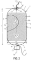
- FIG. 2
- is a partially cut-out explanatory drawing illustrating the state of reinforcing layers in a body portion of the vertical pneumatic fender illustrated in
FIG. 1 in a neutral state. - FIG. 3
- is an explanatory drawing illustrating the state of reinforcing layers in a hemispherical portion illustrated in
FIG. 2 . - FIG. 4
- is a partially magnified cross-sectional view of the body portion of the vertical pneumatic fender illustrated in
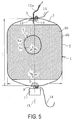
FIG. 2 . - FIG. 5
- is a partially cut-out explanatory drawing illustrating the state of reinforcing layers when a body portion has expanded in diameter.
- The vertical pneumatic fender according to the present invention will now be described on the basis of the embodiments illustrated in the drawings.
- As illustrated in
FIGS. 1 to 3 , a vertical pneumatic fender 1 (hereinafter, referred to as fender 1) according to the present invention comprises acylindrical body portion 2 and bowl-shapedhemispherical portions 3 at both ends thereof. Each of thehemispherical portions 3 is provided with afitting 9. An internal space of thefender 1 contains a predetermined amount of ballast water W. - A
safety valve 10 is provided in thefitting 9 of the upperhemispherical portion 3, and apressure sensor 13 is provided in or near thefitting 9. Thesafety valve 10 opens when the internal pressure of thefender 1 exceeds a preset maximum pressure, venting air a within the internal space to the exterior and reducing the internal pressure. Thepressure sensor 13 detects the internal pressure of thefender 1. - An
injection tube 12a of anair injection device 12 is further connected to thefitting 9 of the upperhemispherical portion 3. Theinjection tube 12a is a pipe, hose, or equivalent member; ordinarily, theair injection device 12 is inactive, and theinjection tube 12a is closed. When necessary, theair injection device 12 injects additional air a into the internal space of thefender 1. Theair injection device 12 can be, for example, a built-in power source operated or non-electrically operated air injection cylinder. - A
bob 11 is connected to thefitting 9 of the lowerhemispherical portion 3. One end of aguy chain 14 is connected to each of thefittings 9. The other ends of theguy chains 14 are fastened to a quay 16 by anchors or the like. - The ballast water W and the
bob 11 apply a vertical downward force to thefender 1, and the balance between this vertical downward force and the buoyancy of thefender 1 keeps thefender 1 in an upright position with thehemispherical portions 3 on both ends disposed above and below. - As illustrated in
FIG. 4 , thebody portion 2 is constituted by a plurality of reinforcinglayers 5 layered between aninner rubber layer 4 and anouter rubber layer 7. In this embodiment, six reinforcing layers 5 (5a to 5f) are layered. The number of layers of reinforcinglayers 5 is, for example, roughly from 6 to 12. An intermediate rubber layer 8 (8a to 8e) is disposed between each of the reinforcing layers 5. - Each of the reinforcing
layers 5 is a cord layer formed from a plurality of cords 6a (6b) arranged in parallel. Thecords 6a, 6b of adjacent layered reinforcinglayers 5 intersect, and are disposed with a predetermined cord angle A with respect to the cylinder axial direction (cylinder center line CL) of thebody portion 2. In other words, the reinforcinglayer 5a of the inner peripheral side first layer, the reinforcinglayer 5c of the third layer, and the reinforcinglayer 5e of the fifth layer have a cord angle A in the same direction. The reinforcinglayer 5b of the inner peripheral side second layer, the reinforcinglayer 5d of the fourth layer, and the reinforcinglayer 5f of the sixth layer have a cord angle A in the same direction, and, this cord angle A has the opposite orientation to that of the reinforcinglayers - Steel cords or organic fiber cords or the like can be used as the
cords 6a, 6b. The outer diameter of thecords 6a, 6b is, for example, roughly from 0.5 mm to 1.5 mm both inclusive. - The
hemispherical portions 3 have a layered configuration with a plurality of reinforcing layers between theinner rubber layer 4 and theouter rubber layer 7. A reinforcing layer (cord layer) formed fromcords 6c disposed in a radial manner, and a reinforcing layer (cord layer) formed from cords 6d disposed in the circumferential direction are alternately layered. The specification of thecords 6c, 6d is basically the same as that of thecords 6a, 6b of the reinforcinglayers 5 of thebody portion 2. - In a neutral state, the thickness of the
intermediate rubber layers 8 of thefender 1 of the present invention is from 1 mm to 5 mm both inclusive, and the cord angle A is from 15° to 45° both inclusive. A "neutral state" is one in which the internal space of thefender 1 is at the specified internal pressure for ordinary use. Specified internal pressure is, for example, roughly from 50 kPa to 100 kPa both inclusive. - In a conventional pneumatic fender, only very thin adhesive rubber is disposed between two reinforcing layers that are adjacent to each other in the radial direction in order to bond them together. In the present invention, as illustrated in
FIG. 4 , theintermediate rubber layers 8 are also deliberately interposed along with the adhesive rubber. For example, natural rubber, butyl rubber, styrene butadiene rubber, acrylonitrile butadiene rubber, or the like are used as the rubber forming theintermediate rubber layer 8. - For example natural rubber, butyl rubber, styrene butadiene rubber, acrylonitrile butadiene rubber, or the like are used as the rubber forming the
inner rubber layer 4. For example natural rubber, styrene butadiene rubber, acrylonitrile butadiene rubber, ethylene propylene rubber, or the like are used as the rubber forming theouter rubber layer 7. When thefender 1 is in a neutral state, the thickness of theinner rubber layer 4 is, for example, roughly from 2 mm to 5 mm both inclusive, and the thickness of theouter rubber layer 7 is, for example, roughly from 3 mm to 12 mm both inclusive. - When the
fender 1 is mounted at an installation location for actual use, ballast water W and air a are injected through the valve installed in thefitting 9 into the internal space. When air a has been injected until specified internal pressure is reached and thefender 1 is in a neutral state, the cord angle A of thecords 6a, 6b of the various reinforcinglayers 5 is from 15° to 45° both inclusive. In this state, theair injection device 12 remains inactive. - Ordinarily, the
fender 1 is used in this neutral state, and contacts avessel 15 moored to thequay 16. If, for example, a tsunami causes thevessel 15 moored to thequay 16 to suddenly rock and excessively compress thefender 1, the internal pressure of thefender 1 will abnormally increase. In such an event, theair injection device 12 is configured to be activated when thepressure sensor 13 detects an internal pressure exceeding a reference pressure level. The reference pressure level is a pressure level set a predetermined level higher than the specified pressure in the neutral state such that thefender 1 will not burst. - When the
air injection device 12 is activated, additional air a is immediately injected into the internal space of thefender 1. The injection of the additional air a causes the cord angle A of thecords 6a, 6b of the various reinforcinglayers 5 to increase to roughly a stable angle of repose (from 54° to 55° both inclusive). During this process, the presence of theintermediate rubber layers 8 causes the variousintermediate rubber layers 8 to exhibit a suitable level of shear deformation. As a result, the cord angle A smoothly varies up to roughly the angle of repose, as illustrated inFIG. 5 , thereby allowing thebody portion 2 to rapidly increase greatly in diameter and inflate. - The internal pressure of the
fender 1 when, for example, additional air a has been injected until thebody portion 2 is in a state of maximum expansion and inflation is, for example, about 150 kPa. - A cord angle A in the neutral state of less than 15° is undesirable, as excessive amounts of shear stress will be generated in the
intermediate rubber layers 8 in order to increase the cord angle A to roughly the angle of repose. Conversely, a cord angle A exceeding 45° will decrease the extent to which thebody portion 2 increases in diameter from the neutral state when additional air a is injected. For these reasons, the cord angle A in the neutral state is set to from 15° to 45° both inclusive. - When the
fender 1 is excessively compressed as described above, thebody portion 2 expands in diameter, rapidly increasing the cubic capacity of the internal space and increasing the tolerate level of compression. This causes a rapid and dramatic increase in the energy-absorbing capability of thefender 1. In addition, internal pressure is increased by the injection of the additional air a into the internal space, which also increases the energy-absorbing capability of thefender 1. Thefender 1 is thus capable of sufficiently responding to sudden increases in berthing impact energy caused by sudden rocking of a mooredvessel 15 without bursting. - If the internal pressure of the
fender 1 increases even further and exceeds the maximum internal pressure, thesafety valve 10 opens, thereby venting air a within the internal space to the exterior and reducing internal pressure. If air a is continuously vented to the exterior until the internal pressure of thefender 1 falls to or below a minimum internal pressure, thepressure sensor 13 detects this situation and activates theair injection device 12, causing additional air a to be injected into the internal space until specified internal pressure is reached. - Using an air injection cylinder operated by a built-in power source or a non-electrically operated air injection cylinder (i.e., one in which the valve opens mechanically) as the
air injection device 12 allows additional air a to be injected into the internal space of thefender 1 without the need for an external power source. This reliably allows for a dramatic increase in the energy absorption of thefender 1 even during emergency situations such as power outages. - Mooring the upper and lower ends of the
fender 1 to thequay 16 viaguy chains 14 as in the present embodiment keeps thefender 1 from being unintentionally swept away. - If the thickness of the
intermediate rubber layers 8 is less than 1 mm, it will be difficult to obtain sufficient shear deformation when expanding thebody portion 2; if the thickness exceeds 5 mm, the weight of thefender 1 will be excessive. For these reasons, the thickness of theintermediate rubber layers 8 is preferably from 1 mm to 5 mm both inclusive. - The 100% modulus of the rubber forming the
intermediate rubber layers 8 is more preferably from 0.5 MPa to 5.0 MPa both inclusive. If the 100% modulus of the rubber forming theintermediate rubber layers 8 is less than 0.5 MPa, thebody portion 2 will take time to contract and reduce in diameter, and may not return to its original diameter. Conversely, if the 100% modulus exceeds 5.0 MPa, the shear force of theintermediate rubber layers 8 during expansion will increase, impeding deformation and making it difficult for thebody portion 2 to sufficiently increase in diameter. - In the present embodiment, all of the
intermediate rubber layers 8 have identical thicknesses when in the neutral state; however, an arrangement in which the thickness of theintermediate rubber layers 8 increases the closer theintermediate rubber layers 8 are to the outer circumferential side of the fender is also possible. When thebody portion 2 increases in diameter, higher levels of shear deformation may be necessary the closer theintermediate rubber layers 8 are to the exterior; thus, such an arrangement is advantageous in keeping excessive loads from being placed on some of theintermediate rubber layers 8 when thebody portion 2 expands. -
- 1 Pneumatic fender
- 2 Body portion
- 3 Hemispherical portion
- 4 Inner rubber layer
- 5, 5a, 5b, 5c, 5d, 5e, 5f Reinforcing layer
- 6a, 6b, 6c, 6d Cord
- 7 Outer rubber layer
- 8, 8a, 8b, 8c, 8d, 8e, 8f Intermediate rubber layer
- 9 Fitting
- 10 Safety valve
- 11 Bob
- 12 Air injection device
- 12a Injection tube
- 13 Pressure sensor
- 14 Guy chain
- 15 Vessel
- 16 Quay
- W Ballast water
Claims (5)
- A vertical pneumatic fender comprisinga cylindrical body portion; andhemispherical portions at both ends of the cylindrical body portion, the body portion being constituted by a plurality of reinforcing layers layered between an inner rubber layer and an outer rubber layer, the reinforcing layers being cord layers formed from a multiplicity of cords arranged in parallel,cords in adjacently layered upper and lower reinforcing layers being disposed so as to intersect one another at a predetermined cord angle with respect to a cylinder axial direction,
a bob being connected to the lower hemispherical portion, and ballast water being contained within an internal space of the fender, wherein the fender is characterized in that:intermediate rubber layers are interposed between the reinforcing layers, the cord angle is set to from 15° to 45° both inclusive in a neutral state, andan air injection device for injecting additional air is connected to the internal space. - The vertical pneumatic fender according to claim 1, wherein
the air injection device is a built-in power source operated or non-electrically operated air injection cylinder. - The vertical pneumatic fender according to claim 1 or 2, wherein
the intermediate rubber layers have thicknesses of from 1 mm to 5 mm both inclusive in a neutral state. - The vertical pneumatic fender according to any one of claims 1 to 3, wherein
the rubber making up the intermediate rubber layer has a 100% modulus of from 0.5 MPa to 5.0 MPa both inclusive. - The vertical pneumatic fender according to any one of claims 1 to 4, wherein
the intermediate rubber layers increase in neutral-state thickness the closer the intermediate rubber layers are to an outer circumferential side of the fender.
Applications Claiming Priority (2)
| Application Number | Priority Date | Filing Date | Title |
|---|---|---|---|
| JP2013100244A JP6136556B2 (en) | 2013-05-10 | 2013-05-10 | Vertical pneumatic fender |
| PCT/JP2014/060096 WO2014181623A1 (en) | 2013-05-10 | 2014-04-07 | Vertical pneumatic fender |
Publications (3)
| Publication Number | Publication Date |
|---|---|
| EP2995720A1 true EP2995720A1 (en) | 2016-03-16 |
| EP2995720A4 EP2995720A4 (en) | 2016-11-09 |
| EP2995720B1 EP2995720B1 (en) | 2017-12-27 |
Family
ID=51867105
Family Applications (1)
| Application Number | Title | Priority Date | Filing Date |
|---|---|---|---|
| EP14793982.1A Not-in-force EP2995720B1 (en) | 2013-05-10 | 2014-04-07 | Vertical pneumatic fender |
Country Status (6)
| Country | Link |
|---|---|
| US (1) | US9499243B2 (en) |
| EP (1) | EP2995720B1 (en) |
| JP (1) | JP6136556B2 (en) |
| KR (1) | KR101683645B1 (en) |
| CN (1) | CN105102722B (en) |
| WO (1) | WO2014181623A1 (en) |
Families Citing this family (16)
| Publication number | Priority date | Publication date | Assignee | Title |
|---|---|---|---|---|
| JP5565434B2 (en) * | 2012-04-27 | 2014-08-06 | 横浜ゴム株式会社 | Pneumatic fender |
| JP5790637B2 (en) * | 2012-12-20 | 2015-10-07 | 横浜ゴム株式会社 | Pneumatic fender |
| JP6255965B2 (en) * | 2013-09-30 | 2018-01-10 | 横浜ゴム株式会社 | Vertical pneumatic fender and monitoring method thereof |
| US9816241B2 (en) * | 2014-03-31 | 2017-11-14 | The Yokohama Rubber Co., Ltd. | Pneumatic fender and mouth piece metal for pneumatic fender |
| JP2016204907A (en) * | 2015-04-20 | 2016-12-08 | 横浜ゴム株式会社 | Protective cover for horizontal-type pneumatic fender, horizontal-type pneumatic fender, and method of use of horizontal-type pneumatic fender |
| JP2016204908A (en) * | 2015-04-20 | 2016-12-08 | 横浜ゴム株式会社 | Protective cover for vertical-type pneumatic fender, vertical-type pneumatic fender, and method of use of vertical-type pneumatic fender |
| JP6531480B2 (en) * | 2015-04-20 | 2019-06-19 | 横浜ゴム株式会社 | Protective cover for horizontal pneumatic fenders and usage of horizontal pneumatic fenders and horizontal pneumatic fenders |
| JP6524778B2 (en) * | 2015-04-20 | 2019-06-05 | 横浜ゴム株式会社 | Use of protective covers for vertical pneumatic fenders and use of vertical pneumatic fenders and vertical pneumatic fenders |
| CN106005308B (en) * | 2016-06-21 | 2017-11-17 | 江苏科技大学 | A kind of combined float type ship side protector |
| CN106864690A (en) * | 2017-04-07 | 2017-06-20 | 青岛哈工程船舶科技有限公司 | A kind of ballast facility of ships and light boats by side anticollision device |
| WO2019012871A1 (en) * | 2017-07-12 | 2019-01-17 | 横浜ゴム株式会社 | Pneumatic fender |
| CN108545157A (en) * | 2018-05-16 | 2018-09-18 | 安徽工程大学 | A kind of adjustable shipping anti-collision facility |
| JP7180386B2 (en) | 2019-01-09 | 2022-11-30 | 横浜ゴム株式会社 | pneumatic fender |
| JP7180397B2 (en) | 2019-01-16 | 2022-11-30 | 横浜ゴム株式会社 | Pneumatic fender and its manufacturing method |
| KR102861717B1 (en) * | 2022-11-01 | 2025-09-18 | (주)동양기업 | Pneumatic fender structure for ship coming alongside pier |
| JP7719403B1 (en) | 2024-05-20 | 2025-08-06 | 横浜ゴム株式会社 | System and method for remote management of pneumatic fenders |
Family Cites Families (12)
| Publication number | Priority date | Publication date | Assignee | Title |
|---|---|---|---|---|
| US3276414A (en) * | 1965-04-27 | 1966-10-04 | Theodore T Lee | Marine fender |
| JPS5928689B2 (en) | 1978-03-03 | 1984-07-14 | 株式会社ブリヂストン | Pneumatic fencing material with cylindrical body as impact receiving surface |
| JPS6051211A (en) * | 1983-08-29 | 1985-03-22 | Yokohama Rubber Co Ltd:The | Fender |
| JP2941570B2 (en) * | 1992-07-30 | 1999-08-25 | 株式会社フジクラ | Fiberscope |
| JPH06193031A (en) * | 1992-12-28 | 1994-07-12 | Yokohama Rubber Co Ltd:The | Assembly type pneumatic fender |
| JP3966589B2 (en) | 1997-10-17 | 2007-08-29 | 横浜ゴム株式会社 | Vertical pneumatic fender |
| JP2003090025A (en) * | 2001-09-14 | 2003-03-28 | Yokohama Rubber Co Ltd:The | Air fender protection cover |
| JP4407569B2 (en) * | 2005-05-13 | 2010-02-03 | 横浜ゴム株式会社 | Pneumatic fender |
| KR200454901Y1 (en) * | 2007-08-01 | 2011-08-04 | 김지현 | Shock-resistant fender |
| CN201512105U (en) * | 2009-09-26 | 2010-06-23 | 青岛吉尔工程橡胶有限公司 | Tapered rubber fenders with reinforcement |
| CN101698424A (en) * | 2009-10-27 | 2010-04-28 | 钟爱民 | Combined type fender |
| AU2011263097B2 (en) * | 2010-06-11 | 2014-04-17 | The Yokohama Rubber Co., Ltd. | Pneumatic fender management system |
-
2013
- 2013-05-10 JP JP2013100244A patent/JP6136556B2/en active Active
-
2014
- 2014-04-07 CN CN201480019016.5A patent/CN105102722B/en not_active Expired - Fee Related
- 2014-04-07 KR KR1020157027871A patent/KR101683645B1/en not_active Expired - Fee Related
- 2014-04-07 US US14/890,249 patent/US9499243B2/en not_active Expired - Fee Related
- 2014-04-07 EP EP14793982.1A patent/EP2995720B1/en not_active Not-in-force
- 2014-04-07 WO PCT/JP2014/060096 patent/WO2014181623A1/en not_active Ceased
Also Published As
| Publication number | Publication date |
|---|---|
| JP6136556B2 (en) | 2017-05-31 |
| JP2014218866A (en) | 2014-11-20 |
| EP2995720B1 (en) | 2017-12-27 |
| US9499243B2 (en) | 2016-11-22 |
| US20160083056A1 (en) | 2016-03-24 |
| CN105102722A (en) | 2015-11-25 |
| KR20150119490A (en) | 2015-10-23 |
| CN105102722B (en) | 2017-09-19 |
| EP2995720A4 (en) | 2016-11-09 |
| WO2014181623A1 (en) | 2014-11-13 |
| KR101683645B1 (en) | 2016-12-07 |
Similar Documents
| Publication | Publication Date | Title |
|---|---|---|
| EP2995720B1 (en) | Vertical pneumatic fender | |
| AU2013253477B2 (en) | Pneumatic fender | |
| CN116335739B (en) | A multi-stage pressure relief and anti-collision device suitable for anchor support | |
| KR102312345B1 (en) | pneumatic fender | |
| US20120091783A1 (en) | Expansion device for breaking solid material, use of the device and method for producing it | |
| US10968587B2 (en) | Pneumatic fender | |
| US10011466B1 (en) | Lifting bag device with recessed gas inlet | |
| US11299243B2 (en) | Pneumatic fender and manufacturing method therefor | |
| JP4555200B2 (en) | Air spring stopper | |
| JP2008179255A (en) | Pneumatic tire | |
| CN119546436A (en) | Rubber product and method for producing the same | |
| Sakakibara et al. | Development of pneumatic type buoy for surface and subsea region |
Legal Events
| Date | Code | Title | Description |
|---|---|---|---|
| PUAI | Public reference made under article 153(3) epc to a published international application that has entered the european phase |
Free format text: ORIGINAL CODE: 0009012 |
|
| 17P | Request for examination filed |
Effective date: 20151209 |
|
| AK | Designated contracting states |
Kind code of ref document: A1 Designated state(s): AL AT BE BG CH CY CZ DE DK EE ES FI FR GB GR HR HU IE IS IT LI LT LU LV MC MK MT NL NO PL PT RO RS SE SI SK SM TR |
|
| AX | Request for extension of the european patent |
Extension state: BA ME |
|
| DAX | Request for extension of the european patent (deleted) | ||
| A4 | Supplementary search report drawn up and despatched |
Effective date: 20161007 |
|
| RIC1 | Information provided on ipc code assigned before grant |
Ipc: B63B 59/02 20060101ALN20160930BHEP Ipc: E02B 3/26 20060101AFI20160930BHEP Ipc: E02B 17/00 20060101ALI20160930BHEP |
|
| RIC1 | Information provided on ipc code assigned before grant |
Ipc: E02B 17/00 20060101ALI20170710BHEP Ipc: B63B 59/02 20060101ALN20170710BHEP Ipc: E02B 3/26 20060101AFI20170710BHEP |
|
| GRAP | Despatch of communication of intention to grant a patent |
Free format text: ORIGINAL CODE: EPIDOSNIGR1 |
|
| STAA | Information on the status of an ep patent application or granted ep patent |
Free format text: STATUS: GRANT OF PATENT IS INTENDED |
|
| INTG | Intention to grant announced |
Effective date: 20170918 |
|
| GRAS | Grant fee paid |
Free format text: ORIGINAL CODE: EPIDOSNIGR3 |
|
| GRAA | (expected) grant |
Free format text: ORIGINAL CODE: 0009210 |
|
| STAA | Information on the status of an ep patent application or granted ep patent |
Free format text: STATUS: THE PATENT HAS BEEN GRANTED |
|
| AK | Designated contracting states |
Kind code of ref document: B1 Designated state(s): AL AT BE BG CH CY CZ DE DK EE ES FI FR GB GR HR HU IE IS IT LI LT LU LV MC MK MT NL NO PL PT RO RS SE SI SK SM TR |
|
| REG | Reference to a national code |
Ref country code: GB Ref legal event code: FG4D |
|
| REG | Reference to a national code |
Ref country code: CH Ref legal event code: EP |
|
| REG | Reference to a national code |
Ref country code: AT Ref legal event code: REF Ref document number: 958411 Country of ref document: AT Kind code of ref document: T Effective date: 20180115 |
|
| REG | Reference to a national code |
Ref country code: IE Ref legal event code: FG4D |
|
| REG | Reference to a national code |
Ref country code: DE Ref legal event code: R096 Ref document number: 602014019190 Country of ref document: DE |
|
| REG | Reference to a national code |
Ref country code: FR Ref legal event code: PLFP Year of fee payment: 5 |
|
| REG | Reference to a national code |
Ref country code: NL Ref legal event code: FP |
|
| PG25 | Lapsed in a contracting state [announced via postgrant information from national office to epo] |
Ref country code: LT Free format text: LAPSE BECAUSE OF FAILURE TO SUBMIT A TRANSLATION OF THE DESCRIPTION OR TO PAY THE FEE WITHIN THE PRESCRIBED TIME-LIMIT Effective date: 20171227 Ref country code: FI Free format text: LAPSE BECAUSE OF FAILURE TO SUBMIT A TRANSLATION OF THE DESCRIPTION OR TO PAY THE FEE WITHIN THE PRESCRIBED TIME-LIMIT Effective date: 20171227 |
|
| PGFP | Annual fee paid to national office [announced via postgrant information from national office to epo] |
Ref country code: NL Payment date: 20180314 Year of fee payment: 5 Ref country code: GB Payment date: 20180329 Year of fee payment: 5 |
|
| REG | Reference to a national code |
Ref country code: LT Ref legal event code: MG4D |
|
| REG | Reference to a national code |
Ref country code: AT Ref legal event code: MK05 Ref document number: 958411 Country of ref document: AT Kind code of ref document: T Effective date: 20171227 |
|
| PG25 | Lapsed in a contracting state [announced via postgrant information from national office to epo] |
Ref country code: HR Free format text: LAPSE BECAUSE OF FAILURE TO SUBMIT A TRANSLATION OF THE DESCRIPTION OR TO PAY THE FEE WITHIN THE PRESCRIBED TIME-LIMIT Effective date: 20171227 Ref country code: LV Free format text: LAPSE BECAUSE OF FAILURE TO SUBMIT A TRANSLATION OF THE DESCRIPTION OR TO PAY THE FEE WITHIN THE PRESCRIBED TIME-LIMIT Effective date: 20171227 Ref country code: BG Free format text: LAPSE BECAUSE OF FAILURE TO SUBMIT A TRANSLATION OF THE DESCRIPTION OR TO PAY THE FEE WITHIN THE PRESCRIBED TIME-LIMIT Effective date: 20180327 Ref country code: RS Free format text: LAPSE BECAUSE OF FAILURE TO SUBMIT A TRANSLATION OF THE DESCRIPTION OR TO PAY THE FEE WITHIN THE PRESCRIBED TIME-LIMIT Effective date: 20171227 Ref country code: GR Free format text: LAPSE BECAUSE OF FAILURE TO SUBMIT A TRANSLATION OF THE DESCRIPTION OR TO PAY THE FEE WITHIN THE PRESCRIBED TIME-LIMIT Effective date: 20180328 |
|
| PGFP | Annual fee paid to national office [announced via postgrant information from national office to epo] |
Ref country code: FR Payment date: 20180315 Year of fee payment: 5 |
|
| REG | Reference to a national code |
Ref country code: NO Ref legal event code: T2 Effective date: 20171227 |
|
| PG25 | Lapsed in a contracting state [announced via postgrant information from national office to epo] |
Ref country code: SK Free format text: LAPSE BECAUSE OF FAILURE TO SUBMIT A TRANSLATION OF THE DESCRIPTION OR TO PAY THE FEE WITHIN THE PRESCRIBED TIME-LIMIT Effective date: 20171227 Ref country code: EE Free format text: LAPSE BECAUSE OF FAILURE TO SUBMIT A TRANSLATION OF THE DESCRIPTION OR TO PAY THE FEE WITHIN THE PRESCRIBED TIME-LIMIT Effective date: 20171227 Ref country code: CY Free format text: LAPSE BECAUSE OF FAILURE TO SUBMIT A TRANSLATION OF THE DESCRIPTION OR TO PAY THE FEE WITHIN THE PRESCRIBED TIME-LIMIT Effective date: 20171227 Ref country code: ES Free format text: LAPSE BECAUSE OF FAILURE TO SUBMIT A TRANSLATION OF THE DESCRIPTION OR TO PAY THE FEE WITHIN THE PRESCRIBED TIME-LIMIT Effective date: 20171227 Ref country code: CZ Free format text: LAPSE BECAUSE OF FAILURE TO SUBMIT A TRANSLATION OF THE DESCRIPTION OR TO PAY THE FEE WITHIN THE PRESCRIBED TIME-LIMIT Effective date: 20171227 |
|
| PGFP | Annual fee paid to national office [announced via postgrant information from national office to epo] |
Ref country code: NO Payment date: 20180410 Year of fee payment: 5 |
|
| PG25 | Lapsed in a contracting state [announced via postgrant information from national office to epo] |
Ref country code: IS Free format text: LAPSE BECAUSE OF FAILURE TO SUBMIT A TRANSLATION OF THE DESCRIPTION OR TO PAY THE FEE WITHIN THE PRESCRIBED TIME-LIMIT Effective date: 20180427 Ref country code: RO Free format text: LAPSE BECAUSE OF FAILURE TO SUBMIT A TRANSLATION OF THE DESCRIPTION OR TO PAY THE FEE WITHIN THE PRESCRIBED TIME-LIMIT Effective date: 20171227 Ref country code: AT Free format text: LAPSE BECAUSE OF FAILURE TO SUBMIT A TRANSLATION OF THE DESCRIPTION OR TO PAY THE FEE WITHIN THE PRESCRIBED TIME-LIMIT Effective date: 20171227 Ref country code: SM Free format text: LAPSE BECAUSE OF FAILURE TO SUBMIT A TRANSLATION OF THE DESCRIPTION OR TO PAY THE FEE WITHIN THE PRESCRIBED TIME-LIMIT Effective date: 20171227 Ref country code: PL Free format text: LAPSE BECAUSE OF FAILURE TO SUBMIT A TRANSLATION OF THE DESCRIPTION OR TO PAY THE FEE WITHIN THE PRESCRIBED TIME-LIMIT Effective date: 20171227 |
|
| PGFP | Annual fee paid to national office [announced via postgrant information from national office to epo] |
Ref country code: IT Payment date: 20180420 Year of fee payment: 5 |
|
| REG | Reference to a national code |
Ref country code: DE Ref legal event code: R097 Ref document number: 602014019190 Country of ref document: DE |
|
| REG | Reference to a national code |
Ref country code: DE Ref legal event code: R119 Ref document number: 602014019190 Country of ref document: DE |
|
| PLBE | No opposition filed within time limit |
Free format text: ORIGINAL CODE: 0009261 |
|
| STAA | Information on the status of an ep patent application or granted ep patent |
Free format text: STATUS: NO OPPOSITION FILED WITHIN TIME LIMIT |
|
| PG25 | Lapsed in a contracting state [announced via postgrant information from national office to epo] |
Ref country code: MC Free format text: LAPSE BECAUSE OF FAILURE TO SUBMIT A TRANSLATION OF THE DESCRIPTION OR TO PAY THE FEE WITHIN THE PRESCRIBED TIME-LIMIT Effective date: 20171227 Ref country code: DK Free format text: LAPSE BECAUSE OF FAILURE TO SUBMIT A TRANSLATION OF THE DESCRIPTION OR TO PAY THE FEE WITHIN THE PRESCRIBED TIME-LIMIT Effective date: 20171227 |
|
| REG | Reference to a national code |
Ref country code: CH Ref legal event code: PL |
|
| 26N | No opposition filed |
Effective date: 20180928 |
|
| REG | Reference to a national code |
Ref country code: BE Ref legal event code: MM Effective date: 20180430 |
|
| REG | Reference to a national code |
Ref country code: IE Ref legal event code: MM4A |
|
| PG25 | Lapsed in a contracting state [announced via postgrant information from national office to epo] |
Ref country code: LU Free format text: LAPSE BECAUSE OF NON-PAYMENT OF DUE FEES Effective date: 20180407 Ref country code: DE Free format text: LAPSE BECAUSE OF NON-PAYMENT OF DUE FEES Effective date: 20181101 |
|
| PG25 | Lapsed in a contracting state [announced via postgrant information from national office to epo] |
Ref country code: BE Free format text: LAPSE BECAUSE OF NON-PAYMENT OF DUE FEES Effective date: 20180430 Ref country code: SI Free format text: LAPSE BECAUSE OF FAILURE TO SUBMIT A TRANSLATION OF THE DESCRIPTION OR TO PAY THE FEE WITHIN THE PRESCRIBED TIME-LIMIT Effective date: 20171227 Ref country code: LI Free format text: LAPSE BECAUSE OF NON-PAYMENT OF DUE FEES Effective date: 20180430 Ref country code: CH Free format text: LAPSE BECAUSE OF NON-PAYMENT OF DUE FEES Effective date: 20180430 |
|
| PG25 | Lapsed in a contracting state [announced via postgrant information from national office to epo] |
Ref country code: IE Free format text: LAPSE BECAUSE OF NON-PAYMENT OF DUE FEES Effective date: 20180407 |
|
| REG | Reference to a national code |
Ref country code: NO Ref legal event code: MMEP |
|
| REG | Reference to a national code |
Ref country code: NL Ref legal event code: MM Effective date: 20190501 |
|
| GBPC | Gb: european patent ceased through non-payment of renewal fee |
Effective date: 20190407 |
|
| PG25 | Lapsed in a contracting state [announced via postgrant information from national office to epo] |
Ref country code: GB Free format text: LAPSE BECAUSE OF NON-PAYMENT OF DUE FEES Effective date: 20190407 Ref country code: NO Free format text: LAPSE BECAUSE OF NON-PAYMENT OF DUE FEES Effective date: 20190430 Ref country code: MT Free format text: LAPSE BECAUSE OF NON-PAYMENT OF DUE FEES Effective date: 20180407 Ref country code: NL Free format text: LAPSE BECAUSE OF NON-PAYMENT OF DUE FEES Effective date: 20190501 |
|
| PG25 | Lapsed in a contracting state [announced via postgrant information from national office to epo] |
Ref country code: FR Free format text: LAPSE BECAUSE OF NON-PAYMENT OF DUE FEES Effective date: 20190430 |
|
| PG25 | Lapsed in a contracting state [announced via postgrant information from national office to epo] |
Ref country code: TR Free format text: LAPSE BECAUSE OF FAILURE TO SUBMIT A TRANSLATION OF THE DESCRIPTION OR TO PAY THE FEE WITHIN THE PRESCRIBED TIME-LIMIT Effective date: 20171227 |
|
| PG25 | Lapsed in a contracting state [announced via postgrant information from national office to epo] |
Ref country code: IT Free format text: LAPSE BECAUSE OF NON-PAYMENT OF DUE FEES Effective date: 20190407 |
|
| PG25 | Lapsed in a contracting state [announced via postgrant information from national office to epo] |
Ref country code: PT Free format text: LAPSE BECAUSE OF FAILURE TO SUBMIT A TRANSLATION OF THE DESCRIPTION OR TO PAY THE FEE WITHIN THE PRESCRIBED TIME-LIMIT Effective date: 20171227 |
|
| PG25 | Lapsed in a contracting state [announced via postgrant information from national office to epo] |
Ref country code: SE Free format text: LAPSE BECAUSE OF FAILURE TO SUBMIT A TRANSLATION OF THE DESCRIPTION OR TO PAY THE FEE WITHIN THE PRESCRIBED TIME-LIMIT Effective date: 20171227 Ref country code: MK Free format text: LAPSE BECAUSE OF NON-PAYMENT OF DUE FEES Effective date: 20171227 Ref country code: HU Free format text: LAPSE BECAUSE OF FAILURE TO SUBMIT A TRANSLATION OF THE DESCRIPTION OR TO PAY THE FEE WITHIN THE PRESCRIBED TIME-LIMIT; INVALID AB INITIO Effective date: 20140407 |
|
| PG25 | Lapsed in a contracting state [announced via postgrant information from national office to epo] |
Ref country code: AL Free format text: LAPSE BECAUSE OF FAILURE TO SUBMIT A TRANSLATION OF THE DESCRIPTION OR TO PAY THE FEE WITHIN THE PRESCRIBED TIME-LIMIT Effective date: 20171227 |