EP2995713A1 - A door for closing an opening of a housing of a household appliance for laundry care, a household appliance for laundry care, and a method for manufacturing a respective door - Google Patents
A door for closing an opening of a housing of a household appliance for laundry care, a household appliance for laundry care, and a method for manufacturing a respective door Download PDFInfo
- Publication number
- EP2995713A1 EP2995713A1 EP14184748.3A EP14184748A EP2995713A1 EP 2995713 A1 EP2995713 A1 EP 2995713A1 EP 14184748 A EP14184748 A EP 14184748A EP 2995713 A1 EP2995713 A1 EP 2995713A1
- Authority
- EP
- European Patent Office
- Prior art keywords
- door
- door body
- recess
- housing
- opening
- Prior art date
- Legal status (The legal status is an assumption and is not a legal conclusion. Google has not performed a legal analysis and makes no representation as to the accuracy of the status listed.)
- Granted
Links
- 238000000034 method Methods 0.000 title claims description 19
- 238000004519 manufacturing process Methods 0.000 title claims description 6
- 239000011521 glass Substances 0.000 claims description 13
- 238000007789 sealing Methods 0.000 claims description 10
- 238000005406 washing Methods 0.000 description 20
- 238000013461 design Methods 0.000 description 9
- 239000000463 material Substances 0.000 description 5
- 230000008901 benefit Effects 0.000 description 2
- 238000010276 construction Methods 0.000 description 2
- 239000006059 cover glass Substances 0.000 description 2
- 230000002708 enhancing effect Effects 0.000 description 2
- -1 painting Substances 0.000 description 2
- 230000008569 process Effects 0.000 description 2
- VYZAMTAEIAYCRO-UHFFFAOYSA-N Chromium Chemical compound [Cr] VYZAMTAEIAYCRO-UHFFFAOYSA-N 0.000 description 1
- 238000005452 bending Methods 0.000 description 1
- 229910010293 ceramic material Inorganic materials 0.000 description 1
- 239000011248 coating agent Substances 0.000 description 1
- 238000000576 coating method Methods 0.000 description 1
- 239000003086 colorant Substances 0.000 description 1
- 238000004891 communication Methods 0.000 description 1
- 150000001875 compounds Chemical class 0.000 description 1
- 238000005516 engineering process Methods 0.000 description 1
- 238000011156 evaluation Methods 0.000 description 1
- 239000012530 fluid Substances 0.000 description 1
- PCHJSUWPFVWCPO-UHFFFAOYSA-N gold Chemical compound [Au] PCHJSUWPFVWCPO-UHFFFAOYSA-N 0.000 description 1
- 239000010931 gold Substances 0.000 description 1
- 229910052737 gold Inorganic materials 0.000 description 1
- 238000002347 injection Methods 0.000 description 1
- 239000007924 injection Substances 0.000 description 1
- 238000005259 measurement Methods 0.000 description 1
- 230000007246 mechanism Effects 0.000 description 1
- 238000000465 moulding Methods 0.000 description 1
- 230000003287 optical effect Effects 0.000 description 1
- 238000010422 painting Methods 0.000 description 1
- 239000004033 plastic Substances 0.000 description 1
- 229920003023 plastic Polymers 0.000 description 1
- 239000002994 raw material Substances 0.000 description 1
- 125000006850 spacer group Chemical group 0.000 description 1
- 230000007704 transition Effects 0.000 description 1
- 239000012780 transparent material Substances 0.000 description 1
- XLYOFNOQVPJJNP-UHFFFAOYSA-N water Substances O XLYOFNOQVPJJNP-UHFFFAOYSA-N 0.000 description 1
Images


Classifications
-
- D—TEXTILES; PAPER
- D06—TREATMENT OF TEXTILES OR THE LIKE; LAUNDERING; FLEXIBLE MATERIALS NOT OTHERWISE PROVIDED FOR
- D06F—LAUNDERING, DRYING, IRONING, PRESSING OR FOLDING TEXTILE ARTICLES
- D06F39/00—Details of washing machines not specific to a single type of machines covered by groups D06F9/00 - D06F27/00
- D06F39/12—Casings; Tubs
- D06F39/14—Doors or covers; Securing means therefor
Definitions
- the rear frame 25 presents on his opposite portion a hinge element 29 which is pivotably connected with the rear frame 25 via a hinge pin 30 as well as two hinge bushes 28.
- the group of the before mentioned elements form a mounting group 31. So, this embodiment shows that the door body 13 needs not to be a single component but itself can have or be composed of a plurality of components.
- the handle area in the door body 13 may be represented by a pocket created using a slider in an injection mould.
- the slider may move radially inside the tool and may be driven by a mechanical angled mechanism.
Landscapes
- Engineering & Computer Science (AREA)
- Textile Engineering (AREA)
- Main Body Construction Of Washing Machines And Laundry Dryers (AREA)
Abstract
a door body (13) being adapted to be hinged to the housing (32), wherein the door body (13) has a recess (5) in order to provide a handle for a user, wherein at least a major portion of the recess (5) is formed above a horizontal centre line (17) of the door body (13), the horizontal centre line (17) being defined in a status, in which the door body (13) is hinged to the housing (32).
Description
- The present invention relates to a door for closing an opening of a household appliance for laundry care, the housing having an inner space that can be accessed through the opening in order to allow laundry items to be inserted into the space for the purpose of treating them by the household appliance and/or to allow the laundry items to be removed from the space, the door comprising: a door body being adapted to be hinged to the housing, wherein the door body has a recess in order to provide a handle for a user. The invention further relates to a household appliance for laundry care, the household appliance comprising: a housing; an inner space provided inside the housing, wherein the inner space is adapted to receive the laundry; an opening provided in the housing in order to allow the inner space to be accessed via said opening. Finally, the invention further relates to a method for manufacturing a door for closing an opening of a housing of a household appliance for laundry care, the housing having an inner space that can be accessed through the opening in order to allow laundry items to be inserted into the space for the purpose of treating them by the household appliance and/or to allow the laundry items to be removed from the space, the method comprising: providing a door body being adapted to be hinged to the housing; and providing the door body with a recess in order to allow a user to grasp the door.
- A generic household appliance and a door as well as a method is known from the European
patent application EP 2 455 536 A1 . This document discloses a door for a washing machine having a door hinge in order to hinge the door such that it can be pivoted about a vertical axis at one side of an opening of the washing machine. In order to allow a user to operate the door, the door is provided with a handle which is directly opposite to the hinge. The hinge and the handle are arranged such that they are arranged in a horizontal plane when the door in hinged to the housing of the washing machine. The handle of the door is provided with a recess forming the handle. - Although this technology is currently distributed, it appears that operating the door by a user is difficult. Generally, the door of the laundry machine is situated such that the user has to bend in order to grasp the recess so that the door can be operated. Moreover, applying a force on the door by the user is disadvantageous from ergonomic point of view, since the user has to provide a force transverse to his bending.
- Therefore, it is an object of the invention to improve a door for a laundry machine, a laundry machine and a method therefore in order to allow a more ergonomic operation of the door by the user.
- This object is solved by a door, a household appliance and a method according to the independent claims.
- Especially, according to the invention, a door for closing an opening of a housing of a household appliance for laundry care is proposed. The housing has an inner space that can be accessed through the opening in order to allow laundry items to be inserted into the inner space for the purpose of treating them by the household appliance and/or to allow the laundry items to be removed from the inner space. The inventive door comprises a door body which is adapted to be hinged to the housing. The door body has a recess in order to provide a handle for a user which is preferably situated approximately opposite to the hinge. According to the invention, at least a major portion of the recess is formed above a horizontal centre line of the door body, the horizontal centre line being defined in a status, in which the door body is hinged to the housing.
- The invention recognizes that, on the one hand, the door is to be pivoted about a vertical axis when hinged to the housing, and, on the other hand, that it is easier for the user to act on the door when the handle is located in an, at least slightly, upper portion of the door. This results in the user needing less to be bent itself and simplifying applying an operating force on the door. So, the invention enables more ergonomic operation for the user.
- The door body can provide the complete door as a single part. However, the door body can comprise or be composed of two or more parts which are mounted together in order to form the completed door body. For example, the door body can have an aperture in order to allow a glass member to be located inside the aperture so that a window is formed in the door. The door boby can additionally comprise elements such as a design ring, a cover glass, a door seal, a rear frame, combinations thereof and the like.
- Commonly, the door is hinged to the housing of the laundry machine such that it can be pivoted about a vertical axis. This is connected with the advantage that the door can have any position in a possible pivot range without being fixed in this position by breaking or the like. The door is provided at the housing of the laundry machine in order to close an opening of the housing so that the opening is closed during the intended use of the laundry machine when treating the laundry items inserted into the inner space of the laundry machine.
- The inner space of the laundry machine is commonly provided by a drum, especially a washing drum, which is rotatably arranged inside the housing. In case, the laundry machine is a dryer, the inner space is preferably provided by a dryer drum. However, the inner space can be provided by any other suited element which is adapted to allow containing and treating of the laundry items.
- Laundry items, for example, comprise shirts, jackets, trousers, skirts, dresses, socks, household linen, any other items of a household that can be treated by a laundry machine, and the like. The before-mentioned definitions of the terms are supposed to limit not the scope of the before mentioned terms.
- The horizontal centre line is a virtual line extending through a centre of the door body. It is arranged in a plane trough the door body which is parallel to a plane of the opening when the door is in the closed position. Consequently, the plane extends in one of its dimension in vertical direction.
- Preferably, the recess is shaped as a quarter segment of a toroid. The toroid may correspond to a circular ring. Preferably, the quarter segment is arranged at the door body in an upper portion, most preferably above the horizontal centre line. However, the recess may be substantially arranged opposite to the hinge of the door body, preferably completely above the horizontal centre line. So, a range of a grasping area for the user is provided so that the user himself or herself can be in the most ergonomic position for grasping the recess in order to operate the door.
- Moreover, it is preferred that an outer circumference of the door body is substantially circular. Most preferably, the circumference of the door body is formed in shape with respect to the quarter segment. Especially, the quarter segment can be arranged narrow to the outer circumference of the door body. This allows providing a lever so that the door body can be operated with a minimum of force exerted by the user. Moreover, the circular circumference allows the door body and as a result to reduce material expenditure for the door body and the door, respectively.
- In order to improve secure grasping of the recess, it is preferably suggested that the recess is provided with an undercut. The undercut allows the user to grasp the door body so that a high force can be exerted on the door body, on the one hand, and, on the other hand, sliding off during grasping can be prevented from.
- Advantageously, the undercut projects radially outwardly inside the door body. So, the undercut can be integrally formed with the door body so that no additional elements will be needed. This allows to provide the undercut without the necessity of further material expenses.
- Preferably, dimensions of the undercut vary such that a depth of the undercut is larger at a position close to the horizontal centre line than the depth of the undercut at a position close to a vertical centre line defined in a status, in which the door body is hinged to the housing. This allows the user to find easily an optimal position for grasping the recess only by touching. So, the user may grasp the recess and gets respective information by touching which position in the recess allows opening the door with a minimum force. No further optical feedback for the user needs to be necessary.
- It is moreover preferred that a cover is fixed to the door body, the cover having an aperture adapted to the recess of the door body such that the recess is partially covered by the cover in order to form the undercut. So, the cover can be used, on the one hand, to form the undercut of the recess. For this purpose, the cover may cover the recess partially so that the covered portion of the recess forms the undercut. For example, the aperture can be adapted to the quarter segment such that a radially arranged outer portion of the quarter segment is covered by the cover and an inner portion of the quarter segment is kept free for grasping by the user. Preferably, the cover is adapted to an outer shape of the door body; most preferably, it is arranged at an outer surface of the door body. The cover can be made from plastics, ceramic material, compound material, combinations thereof, or the like.
- According to a preferred embodiment, the recess is arranged close to the circumference of the door body. This allows providing a large lever for introducing the force by the user. Only a small wall between the outer circumference of the door body and the recess is necessary, wherein a wall thickness depend on material characteristics of the door body.
- Preferably, the shape of the recess corresponds to the circumference of the door body. This embodiment allows further improving the rigidity since the force applied to the door by the user can be equally distributed over the extension of the recess.
- According to an advantageous embodiment, the door body is provided with a circumferential seal in order to provide a sealing of the opening when the door body is arranged inside the opening. So, the door body is enabled to close the door opening such that, during common operation of the household appliance, the space is sealed properly. Treatment fluids will consequently be kept inside the inner space. No further support for the sealing is necessary.
- According to a further advantageous embodiment, the door body is provided with a glass member, wherein the glass member is directed to the inner space of the housing in the closed position of the door. This embodiment allows providing a window in the door so that a user may control the status and/or the progress of treatment of the laundry.
- Especially, a household appliance for laundry care according to the invention comprises a housing, an inner space provided inside the housing, wherein the inner space is adapted to receive and to treat the laundry, and an opening provided in the housing in order to allow the inner space to be accessed via said opening. The household appliance further comprises a door according to the invention.
- A household appliance of the generic art includes an apparatus for treating laundry, for instance, a washing machine, a dryer, combinations thereof, and the like.
- The household appliance preferably includes electric devices which realize the determined function or treatment, respectively. The electric devices, for example, may be an electric machine, an electric heater, an inverter, especially a DC converter, combinations thereof, and the like. In order to control the electric devices in a determined way, the household appliance includes a control unit. The control unit in turn can comprise an input unit which allows a user to provide manually inputs for controlling the household appliance. Moreover, the control unit may include a display device in order to display operating statuses to be visually noted by the user. Additionally, the display device and the input device can be integral with each other, for instance, a touch screen, or the like. Finally, the control unit may further comprise sensors as well as evaluation units in order to control the electric devices, parameters such as temperature, water quantity, and the like. The control unit may further comprise a computer unit so that different operations can be selected. The different operations may be selected by input of a user or in dependence on evaluated measurement results of the sensors. The control unit may also be adapted to communicate with external devices, for example, such as a communication terminal, especially a mobile phone, or the like.
- The method according to the invention serves for manufacturing a door for closing an opening of a housing of a household appliance for laundry care. The housing has an inner space that can be accessed through the opening in order to allow laundry items inserted into the space for the purpose of treating them by the household appliance and/or to allow the laundry items to be removed from the space. The inventive method comprises providing a door body being adapted to be hinged to the housing and providing the door body with a recess in order to allow a user to grasp the door. According to the invention, at least a major portion of the recess is formed above a horizontal centre line of the door body, the horizontal centre line being defined in a status, in which the door body is hinged to the housing. Especially, the recess may be formed by using sliders which can be moved in a mold during the molding process of the door body. This allows easy manufacturing of the inventive door.
- Preferably, the recess is provided with an undercut. In order to receive the undercut, the mold may have an additional slider adapted to the shapes of the recess and the undercut so that the undercut can be formed at the same time with the door body without providing any further steps of manufacturing. Moreover, this method step allows producing the undercut integrally with the recess.
- Preferably, the recess is shaped as a quarter segment of a toroid. For this purpose, the mold may be provided with an additional slider being shaped as a toroid or circular ring, respectively. So, the quarter segment can be manufactured with small costs.
- Advantageous embodiments of the door also have to be regarded as advantageous embodiments of the method and the household appliance. For this purpose, apparatus components of the door may be formed as a single component or in combination with other components in order to provide the method steps.
- Additional features of the invention will become apparent from the claims, the figures and a detailed description of an embodiment. All before mentioned features of the description and combinations thereof as well as those of the following detailed description of an embodiment and/or single features shown in the figures and combinations thereof are not only to be used in the respective described combination but also in different combinations or alone without leaving the scope of the invention. Consequently, additional embodiments of the invention have to be regarded as being comprised and disclosed which are not directly shown and described but which are apparent and clear for those skilled in the art by separating combinations of features of the embodiments described.
- An exemplary embodiment of the invention will be described in the following by considering the accompanying drawings in detail. In the figures, equal reference characters designate equal functions and features.
- In the figures show:
- Fig. 1
- a schematic perspective view on a front side of a washing machine according to the invention;
- Fig. 2
- a schematic front view on a door according to the inventionof the washing machine according to
Fig. 1 ; - Fig. 3
- a schematic side view on the door according to
Fig. 2 ; - Fig. 4
- a perspective schematic view of a cutaway of the door according to
Fig. 2 ; - Fig. 5
- a schematic perspective view on a door body of the door according to
Fig. 2 ; - Fig. 6
- a schematic front view of a cutaway of the door body according to
Fig. 5 ; - Fig. 7
- a schematic view according to
Fig. 6 , wherein grasping areas are indicated; - Fig. 8
- in a schematic view a cutaway of a section of the door according to
Fig. 2 in an outer range of the door; - Fig. 9
- a schematic view on a front side of the door body according to
Fig. 6 ; - Fig, 10
- a schematic perspective view of a cutaway of the door body according to
Fig. 9 ; and - Fig. 11
- in a schematic perspective view an exploded assembly drawing of the door according to
Fig. 2 . -
Fig. 1 shows in a schematic perspective view a front side of awashing machine 1 as household appliance for laundry care. Thewashing machine 1 comprises ahousing 32 in which a washing drum 7 is provided inside in order to provide an inner space. The washing drum 7 is adapted to receive and to treat the laundry. Thehousehold appliance 1 further comprises anopening 3 provided in thehousing 32 in order to allow the washing drum 7 to be accessed via saidopening 3. Theopening 3 can be closed by adoor 2 that is hinged to thehousing 32 by ahinge 4 such that thedoor 2 can be pivoted about a vertical axis which is indicated inFig. 1 by an y-axis of a coordinate system. The vertical axis is parallel to the y-axis. - The
door 2 comprises arecess 5 that is adapted to provide a portion of thedoor 2 where a user can grasp thedoor 2 in order to open or close thedoor 2. - The
washing machine 1 further comprises a belt 6 which is adapted to drive the washing drum 7 and which is in turn driven by adriver 8. Thewashing machine 1 further comprises acontrol unit 11 that is connected with an electric power network in order to receive energy therefrom so that thewashing machine 1 is enabled to provide the intended treatment. Thedriver 8 is connected to thecontrol unit 11 via apower court 9 which supplies electric energy to thedriver 8 for driving purposes. Moreover, thecontrol unit 11 is connected with thedriver 8 via acontrol cord 10 in order to provide thedriver 8 with control signals so that the washing drum 7 can be operated according to a control program, i. e. a washing program. - The
control unit 11 is further connected with adisplay 12 that displays operational data and statuses to a user. Presently, thedisplay 12 is further provided with control knobs (not referenced) in order to allow a user to provide an input in order to adjust operating of thewashing machine 1. -
Fig. 2 shows thedoor 2 in a schematic front view as well asFig. 3 in a schematic side view. Thedoor 2 serves for closing theopening 3 of thehousing 32 of thehousehold appliance 1. Thedoor 2 comprises adoor body 13 that is adapted to be hinged to thehousing 32 by ahinge 4. Thedoor body 13 presents arecess 5 in order to provide a handle for a user. At least a major portion of therecess 5 is formed above ahorizontal centre line 17, thehorizontal centre line 17 being defined in a status, in which thedoor body 13 is hinged to thehousing 32. Thehorizontal centre line 17 is parallel orientated to an x-axis shown inFig. 1 . - As can be seen from
Fig. 2 and Fig. 3 , thedoor body 13 is covered by acover 15 which is surrounded by adesign ring 14. Thedoor body 13 presents an outer circumference which is substantially circular. Thecover 15 is provided with anaperture 24 which is located in the range of therecess 5. Therecess 5 is shaped as a quarter segment of a circular ring. Presently, theaperture 24 is adapted to therecess 5. - The
recess 5 of thedoor body 13 is provided with an undercut 16 that projects radially outwardly inside thedoor body 13. Additionally,Fig. 2 shows avertical centre line 18 which is perpendicular according to thehorizontal centre line 17. Both centre lines cross in a centre point of thedoor body 13 and refer to the situation when thedoor 2 is hinged to thehousing 32. Consequently, thevertical centre line 18 is parallel to the y-axis according toFig. 1 , wherein thehorizontal centre line 17 is parallel to the x-axis as shown inFig. 1 . - However, in an alternate embodiment, the
aperture 24 of thecover 15 is formed such that a radially outer portion of therecess 5 is covered, too. Therefore, thecover 15 which is fixed to thedoor body 13 presents together with thedoor body 13 an undercut. -
Fig. 4 shows a cutaway portion in a schematic perspective view of thedoor 2 according toFigs. 2 and 3. Fig. 4 allows enhancing the view on therecess 5 and the undercut 16.Fig. 6 and 7 show a respective portion ofFig. 4 in a frontal view of the door body in the range of therecess 5 in a cutaway view.Fig. 7 corresponds toFig. 6 and differs fromFig. 6 only byarrows Arrow 20 refers to a range for a grasping area, where the user can grasp into therecess 5. The portion indicated byarrow 21 corresponds to a non-grasping area which hinders the user to grasp properly inside therecess 5. This results in avoiding that the user provides a substantial vertical force on thedoor 2 which may affect or damage thehinge 4. So, the shape of therecess 5 leads the user automatically to an ergonomic grasping into therecess 5 in order to operate thedoor 2. InFigs. 6 and 7 , thecover 15 and thedesign ring 14 according toFig. 2 to 5 are removed. - As can be seen additionally from
Fig. 6 and 7 , thedoor body 13 is provided with aglass member 19 in order to allow the user to visually control operation of thehousehold appliance 1 when treating laundry. -
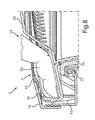
Fig. 8 shows a schematic sectional view of a cutaway according toFig. 3 , wherein a portion of afinger 23 of the user is located inside therecess 5.Fig. 8 shows the mounting situation of thedoor 2, namely, thedoor body 13 presenting therecess 5 and being covered by thecover 15 presenting theaperture 24 in the range of therecess 5. In the present embodiment the undercut 16 is provided by thedoor body 13 itself. - As can also be seen from
Fig. 8 , the undercut 16 is partially covered and enforced by thedesign ring 14. This allows the user to present high forces without damaging thedoor body 13. This is especially advantageous when thedoor 2 is closed and needs to be opened by the user. Often, it is necessary to present a high force for opening thedoor 2 in order to overcome the frictional fixation of thedoor 2 in the closed state. - As can also be seen from
Fig. 8 , theglass member 19, which also may be referred to as door glass, is fixed to thedoor body 13 by a sealingring 22. The sealingring 22 properly fixes theglass member 19 to thedoor body 13 and allows adjusting some clearances which may appear when high temperatures or pressure or the like act on thedoor 2 as a result of the determined operation of thehousehold appliance 1 during treatment of the laundry. -
Fig. 9 shows thedoor body 13 without thecover 15 and thedesign ring 14 in a schematic frontal view. On the right side inFig. 9 , thehinge 4 is located. Moreover,Fig. 9 shows therecess 5 in the left upper portion of thedoor body 13 and theglass member 19 being connected with thedoor body 13 via the sealingring 22.Fig. 10 shows a cutaway in a schematic perspective view of thedoor body 13 according toFig. 9 in the range of therecess 5. As can be seen fromFigs. 9 and 10 , therecess 5 is not continuous in circumferential direction but the radial distance with respect to the centre of thedoor body 13 is larger in the range of thehorizontal centre line 17 than this portion of therecess 5 which is narrow to thevertical centre line 18. -
Fig. 11 shows a schematic exploded assembly drawing of thecomplete door 2. As can be seen fromFig. 11 , thedoor body 13, also referred to as spacer, presents therecess 5. Moreover, thedoor body 13 presents anopening 33 in which is inserted theglass member 19 including the sealingring 22. On the rear side of thedoor body 13, there is provided arear frame 25 enhancing a proper support for theglass member 19 and the sealingring 22 at thedoor body 13. Additionally, therear frame 25 supports ahook 27 as well as apin 26 in order to present an interlocking for thedoor 2 in the closed state. The group comprised ofhook 27 andpin 26 is arranged at thehorizontal centre line 17 opposite to thehinge 4. Consequently, therear frame 25 presents on his opposite portion ahinge element 29 which is pivotably connected with therear frame 25 via a hinge pin 30 as well as twohinge bushes 28. The group of the before mentioned elements form a mountinggroup 31. So, this embodiment shows that thedoor body 13 needs not to be a single component but itself can have or be composed of a plurality of components. - As can be additionally seen from
Fig. 11 , the mountinggroup 31 is covered bycover 15 having theaperture 24 and, finally, by thedesign ring 14. - Summarized, the invention allows integrating handle features to the interior of the door construction so that proper operation can be achieved in two kinds of appliance design concepts:
- deep stamped front panel with integrated doors, especially, where the external surface of the door is aligned with the surface of the front panel so that preferably no side areas of the door are accessible when the door is closed;
- flat stamped front panel with add-on door, especially, where the door comes out of the appliance and some side areas are accessible when the door is closed.
- Depending on variants, the
door 2 can be composed with or withoutfront cover 15, especially a front cover glass, as well as parts that have different colors that could be applied by colored raw material, painting, coating such as chrome, satin, gold, combinations thereof, or the like. Surfaces of thedoor body 13 or a space, respectively, and thecover 15 can also be decorated using tempo prints, hot stamps, stickers, combinations thereof or the like. The dimensions of the handle and its geometry may differ depending on brand design. - The invention is based on the finding that the operation of the
door 2 can be improved from ergonomic point of view. Due to technical construction of thehousehold appliance 1, a door lock or interlocking, respectively, is preferably arranged at a 9 o'clock position and, at the same time, provides the opening function by using the physical grasp which should be placed preferably in the range of this position. - This requirement may interfere with the wish to make the grasping area over a angle range of 90°. Consequently, the invention proposes to visually indicate a 90° access while the recess itself allows only grasping in an angle range that is smaller, preferably arranged in the 9 to 10 o'clock position. However, according to the invention, the grasping range is preferably above the
horizontal centre line 17. In the non-grasping area, the recess is formed such that it does not allow to put the fingers deep enough into therecess 5 in order to provide a proper force on thedoor 2 in order to open thedoor 2. The handle area according to the invention is formed as therecess 5 which may also be formed in thecover 15 which in turn may be made of PMMA-material, or, for instance, other transparent materials such as PC, SAN, combinations thereof or the like. Preferably, the surface of therecess 5 in thecover 15 may directly correspond to therecess 5 of thedoor body 13 in order to provide a smooth surface transition between both elements during an opening process. - The handle area in the
door body 13 may be represented by a pocket created using a slider in an injection mould. The slider may move radially inside the tool and may be driven by a mechanical angled mechanism. - The above described embodiment is determined only to more distinctly describe the invention and is not intended for limitation of the invention. Consequently, functions and components may be modified without departing from the scope of the invention. The advantages and features described in connection with the
door 2 may also be applied to thehousehold appliance 1 according to the invention and the inventive method and reverse. So, especially, device features may be allocated to method features and reverse. -
- 1
- washing machine
- 2
- door
- 3
- opening
- 4
- hinge
- 5
- recess
- 6
- belt
- 7
- washing drum
- 8
- driver
- 9
- power cord
- 10
- control cord
- 11
- control unit
- 12
- display
- 13
- door body
- 14
- design ring
- 15
- cover
- 16
- undercut
- 17
- horizontal centre line
- 18
- vertical centre line
- 19
- glass member
- 20
- grasping area
- 21
- non-grasping area
- 22
- sealing ring
- 23
- finger
- 24
- aperture
- 25
- rear frame
- 26
- pin
- 27
- hook
- 28
- hinge bush
- 29
- hinge element
- 30
- hinge pin
- 31
- mounting group
- 32
- housing
- 33
- opening
Claims (15)
- A door (2) for closing an opening (3) of a housing (32) of a household appliance (1) for laundry care, the housing (32) having an inner space (7) that can be accessed through the opening (3) in order to allow laundry items to be inserted into the inner space (7) for the purpose of treating them by the household appliance (1) and/or to allow the laundry items to be removed from the inner space (7), the door (2) comprising:a door body (13) being adapted to be hinged to the housing (32), wherein the door body (13) has a recess (5) in order to provide a handle for a user,characterized in thatat least a major portion of the recess (5) is formed above a horizontal centre line (17) of the door body (13), the horizontal centre line (17) being defined in a status, in which the door body (13) is hinged to the housing (32).
- The door according to claim 1, characterized in that the recess (5) is shaped as a quarter segment of a toroid.
- The door according to claim 1 or 2, characterized in that an outer circumference of the door body (13) is substantially circular.
- The door according to anyone of the preceding claims, characterized in that the recess (5) is provided with an undercut (16).
- The door according to claim 4, characterized in that the undercut (16) projects radially outwardly inside the door body (13).
- The door according to claim 4 or 5, characterized in that dimensions of the undercut (16) vary such that a depth of the undercut (16) is larger at a position close to the horizontal centre line (17) than the depth of the undercut (16) at a position close to a vertical centre line (18) defined in a status, in which the door body (13) is hinged to the housing (32).
- The door according to anyone of the claims 4 to 6, characterized in that a cover (15) is fixed to the door body (15), the cover (15) having an aperture (24) adapted to the recess (5) of the door body (13) such that the recess (5) is partially covered by the cover (15) in order to form the undercut (16).
- The door according to anyone of the preceding claims, characterized in that the recess (5) is arranged close to the circumference of the door body (13).
- The door according to anyone of the preceding claims, characterized in that the shape of the recess (5) is adapted to correspond to the circumference of the door body (13).
- The door according to anyone of the preceding claims, characterized in that the door body (13) is provided with a circumferential sealing member (22) in order to provide a sealing of the opening (3) when the door body (13) is arranged inside the opening (3) in order to close the door (2).
- The door according to anyone of the preceding claims, characterized in that the door body (13) is provided with a glass member (19), wherein the glass member (19) is directed to the inner space (7) of the housing (32) in the closed position of the door (2).
- A household appliance (1) for laundry care, the household appliance (1) comprising:a housing (32);an inner space (7) provided inside the housing (32), wherein the inner space (7) is adapted to receive the laundry; andan opening (3) provided in the housing (32) in order to allow the inner space (7) to be accessed via said opening (3);characterized bya door (2) according to anyone of the preceding claims.
- A method for manufacturing a door (2) for closing an opening (3) of a housing (32) of a household appliance (1) for laundry care, the housing (32) having an inner space (7) that can be accessed through the opening (3) in order to allow laundry items to be inserted into the inner space (7) for the purpose of treating them by the household appliance (1) and/or to allow the laundry items to be removed from the inner space (7), the method comprising:providing a door body (13) being adapted to be hinged to the housing (32); andproviding the door body (13) with a recess (5) in order to allow a user to grasp the door (2);characterized in thatforming at least a major portion of the recess (5) above a horizontal centre line (17) of the door body (13), the horizontal centre line (17) being defined in a status, in which the door body (13) is hinged to the housing (32).
- The method according to claim 13, characterized in that the recess (5) is provided with an undercut (16).
- The method according to claim 13 or 14, characterized in that the recess (5) is shaped as a quarter segment of a toroid.
Priority Applications (3)
| Application Number | Priority Date | Filing Date | Title |
|---|---|---|---|
| EP14184748.3A EP2995713B1 (en) | 2014-09-15 | 2014-09-15 | A door for closing an opening of a housing of a household appliance for laundry care, a household appliance for laundry care, and a method for manufacturing a respective door |
| PL14184748T PL2995713T3 (en) | 2014-09-15 | 2014-09-15 | A door for closing an opening of a housing of a household appliance for laundry care, a household appliance for laundry care, and a method for manufacturing a respective door |
| ES14184748.3T ES2649723T3 (en) | 2014-09-15 | 2014-09-15 | A door for closing an opening of a housing of an appliance for the treatment of laundry, an appliance for the treatment of laundry and a method for manufacturing a respective door |
Applications Claiming Priority (1)
| Application Number | Priority Date | Filing Date | Title |
|---|---|---|---|
| EP14184748.3A EP2995713B1 (en) | 2014-09-15 | 2014-09-15 | A door for closing an opening of a housing of a household appliance for laundry care, a household appliance for laundry care, and a method for manufacturing a respective door |
Publications (2)
| Publication Number | Publication Date |
|---|---|
| EP2995713A1 true EP2995713A1 (en) | 2016-03-16 |
| EP2995713B1 EP2995713B1 (en) | 2017-11-15 |
Family
ID=51570271
Family Applications (1)
| Application Number | Title | Priority Date | Filing Date |
|---|---|---|---|
| EP14184748.3A Active EP2995713B1 (en) | 2014-09-15 | 2014-09-15 | A door for closing an opening of a housing of a household appliance for laundry care, a household appliance for laundry care, and a method for manufacturing a respective door |
Country Status (3)
| Country | Link |
|---|---|
| EP (1) | EP2995713B1 (en) |
| ES (1) | ES2649723T3 (en) |
| PL (1) | PL2995713T3 (en) |
Cited By (1)
| Publication number | Priority date | Publication date | Assignee | Title |
|---|---|---|---|---|
| DE102017108709B3 (en) | 2017-04-24 | 2018-09-13 | Miele & Cie. Kg | Door handle, door and front-loading household appliance, such as washing machine, tumble dryer or washer-dryer |
Citations (5)
| Publication number | Priority date | Publication date | Assignee | Title |
|---|---|---|---|---|
| US20110023559A1 (en) * | 2009-07-30 | 2011-02-03 | Bsh Home Appliances Corporation | Door hinge for a household appliance door |
| EP2455536A1 (en) | 2010-11-23 | 2012-05-23 | Electrolux Home Products Corporation N.V. | Door for a laundry machine having a door hinge |
| US20120161594A1 (en) * | 2010-12-23 | 2012-06-28 | Kihyuk Kim | Laundry treating apparatus |
| US20120217851A1 (en) * | 2011-02-24 | 2012-08-30 | Sanghun Bae | Laundry treatment apparatus |
| US20130232810A1 (en) * | 2012-03-08 | 2013-09-12 | General Electric Company | Door handle for a washing machine or dryer appliance |
-
2014
- 2014-09-15 EP EP14184748.3A patent/EP2995713B1/en active Active
- 2014-09-15 PL PL14184748T patent/PL2995713T3/en unknown
- 2014-09-15 ES ES14184748.3T patent/ES2649723T3/en active Active
Patent Citations (5)
| Publication number | Priority date | Publication date | Assignee | Title |
|---|---|---|---|---|
| US20110023559A1 (en) * | 2009-07-30 | 2011-02-03 | Bsh Home Appliances Corporation | Door hinge for a household appliance door |
| EP2455536A1 (en) | 2010-11-23 | 2012-05-23 | Electrolux Home Products Corporation N.V. | Door for a laundry machine having a door hinge |
| US20120161594A1 (en) * | 2010-12-23 | 2012-06-28 | Kihyuk Kim | Laundry treating apparatus |
| US20120217851A1 (en) * | 2011-02-24 | 2012-08-30 | Sanghun Bae | Laundry treatment apparatus |
| US20130232810A1 (en) * | 2012-03-08 | 2013-09-12 | General Electric Company | Door handle for a washing machine or dryer appliance |
Cited By (1)
| Publication number | Priority date | Publication date | Assignee | Title |
|---|---|---|---|---|
| DE102017108709B3 (en) | 2017-04-24 | 2018-09-13 | Miele & Cie. Kg | Door handle, door and front-loading household appliance, such as washing machine, tumble dryer or washer-dryer |
Also Published As
| Publication number | Publication date |
|---|---|
| EP2995713B1 (en) | 2017-11-15 |
| PL2995713T3 (en) | 2018-02-28 |
| ES2649723T3 (en) | 2018-01-15 |
Similar Documents
| Publication | Publication Date | Title |
|---|---|---|
| EP1891499B1 (en) | Household appliance having concealable user interface | |
| EP1397816B1 (en) | Control panel assembly for home appliances and method for manufacturing the same | |
| EP3043131A1 (en) | Appliance having a human-machine interface and illuminated handle recess | |
| EP2754746B1 (en) | Washing machine and method of manufacturing door thereof | |
| JP2005058753A5 (en) | ||
| EP2843105A1 (en) | A door assembly for a laundry treatment device and method of operation | |
| JP2011072456A (en) | Electric washing machine | |
| CN102257205A (en) | Domestic appliance, in particular dishwasher | |
| EP2995713B1 (en) | A door for closing an opening of a housing of a household appliance for laundry care, a household appliance for laundry care, and a method for manufacturing a respective door | |
| KR100452372B1 (en) | Door of dryer | |
| US10634364B2 (en) | Operating device for a domestic appliance having a stably positioned annular operating-element front part | |
| US9777420B2 (en) | Washing machine appliance lid assembly | |
| CN102743142A (en) | Appliance door for household appliance and household appliance | |
| KR20060001156A (en) | A dial knob structure and manufacturing method of a washing machine | |
| KR102643352B1 (en) | Laundry treating apparatus | |
| EP2074923A1 (en) | Gasket | |
| EP2848727A1 (en) | Front-loading-type washing machine | |
| US20160012987A1 (en) | Household Electrical Appliance Control Panel and Method of Manufacturing Such a Control Panel | |
| JP5707523B2 (en) | Electric washing machine | |
| EP3844443B1 (en) | Oven with a touch door handle | |
| CN111839171B (en) | Cooking utensil | |
| KR101002552B1 (en) | Appliance utilizing water | |
| JP6177822B2 (en) | Electric washing machine | |
| CN106758032A (en) | For the door closure component and rotary drum washing machine of rotary drum washing machine | |
| CN209235722U (en) | Cooking apparatus |
Legal Events
| Date | Code | Title | Description |
|---|---|---|---|
| PUAI | Public reference made under article 153(3) epc to a published international application that has entered the european phase |
Free format text: ORIGINAL CODE: 0009012 |
|
| AK | Designated contracting states |
Kind code of ref document: A1 Designated state(s): AL AT BE BG CH CY CZ DE DK EE ES FI FR GB GR HR HU IE IS IT LI LT LU LV MC MK MT NL NO PL PT RO RS SE SI SK SM TR |
|
| AX | Request for extension of the european patent |
Extension state: BA ME |
|
| 17P | Request for examination filed |
Effective date: 20160916 |
|
| RBV | Designated contracting states (corrected) |
Designated state(s): AL AT BE BG CH CY CZ DE DK EE ES FI FR GB GR HR HU IE IS IT LI LT LU LV MC MK MT NL NO PL PT RO RS SE SI SK SM TR |
|
| R17P | Request for examination filed (corrected) |
Effective date: 20160916 |
|
| GRAP | Despatch of communication of intention to grant a patent |
Free format text: ORIGINAL CODE: EPIDOSNIGR1 |
|
| INTG | Intention to grant announced |
Effective date: 20170515 |
|
| GRAS | Grant fee paid |
Free format text: ORIGINAL CODE: EPIDOSNIGR3 |
|
| GRAA | (expected) grant |
Free format text: ORIGINAL CODE: 0009210 |
|
| AK | Designated contracting states |
Kind code of ref document: B1 Designated state(s): AL AT BE BG CH CY CZ DE DK EE ES FI FR GB GR HR HU IE IS IT LI LT LU LV MC MK MT NL NO PL PT RO RS SE SI SK SM TR |
|
| REG | Reference to a national code |
Ref country code: CH Ref legal event code: EP Ref country code: GB Ref legal event code: FG4D Ref country code: AT Ref legal event code: REF Ref document number: 946400 Country of ref document: AT Kind code of ref document: T Effective date: 20171115 |
|
| REG | Reference to a national code |
Ref country code: IE Ref legal event code: FG4D |
|
| REG | Reference to a national code |
Ref country code: DE Ref legal event code: R096 Ref document number: 602014017153 Country of ref document: DE |
|
| REG | Reference to a national code |
Ref country code: ES Ref legal event code: FG2A Ref document number: 2649723 Country of ref document: ES Kind code of ref document: T3 Effective date: 20180115 |
|
| REG | Reference to a national code |
Ref country code: NL Ref legal event code: MP Effective date: 20171115 |
|
| REG | Reference to a national code |
Ref country code: LT Ref legal event code: MG4D |
|
| REG | Reference to a national code |
Ref country code: AT Ref legal event code: MK05 Ref document number: 946400 Country of ref document: AT Kind code of ref document: T Effective date: 20171115 |
|
| PG25 | Lapsed in a contracting state [announced via postgrant information from national office to epo] |
Ref country code: LT Free format text: LAPSE BECAUSE OF FAILURE TO SUBMIT A TRANSLATION OF THE DESCRIPTION OR TO PAY THE FEE WITHIN THE PRESCRIBED TIME-LIMIT Effective date: 20171115 Ref country code: FI Free format text: LAPSE BECAUSE OF FAILURE TO SUBMIT A TRANSLATION OF THE DESCRIPTION OR TO PAY THE FEE WITHIN THE PRESCRIBED TIME-LIMIT Effective date: 20171115 Ref country code: NO Free format text: LAPSE BECAUSE OF FAILURE TO SUBMIT A TRANSLATION OF THE DESCRIPTION OR TO PAY THE FEE WITHIN THE PRESCRIBED TIME-LIMIT Effective date: 20180215 Ref country code: SE Free format text: LAPSE BECAUSE OF FAILURE TO SUBMIT A TRANSLATION OF THE DESCRIPTION OR TO PAY THE FEE WITHIN THE PRESCRIBED TIME-LIMIT Effective date: 20171115 Ref country code: NL Free format text: LAPSE BECAUSE OF FAILURE TO SUBMIT A TRANSLATION OF THE DESCRIPTION OR TO PAY THE FEE WITHIN THE PRESCRIBED TIME-LIMIT Effective date: 20171115 |
|
| PG25 | Lapsed in a contracting state [announced via postgrant information from national office to epo] |
Ref country code: HR Free format text: LAPSE BECAUSE OF FAILURE TO SUBMIT A TRANSLATION OF THE DESCRIPTION OR TO PAY THE FEE WITHIN THE PRESCRIBED TIME-LIMIT Effective date: 20171115 Ref country code: LV Free format text: LAPSE BECAUSE OF FAILURE TO SUBMIT A TRANSLATION OF THE DESCRIPTION OR TO PAY THE FEE WITHIN THE PRESCRIBED TIME-LIMIT Effective date: 20171115 Ref country code: RS Free format text: LAPSE BECAUSE OF FAILURE TO SUBMIT A TRANSLATION OF THE DESCRIPTION OR TO PAY THE FEE WITHIN THE PRESCRIBED TIME-LIMIT Effective date: 20171115 Ref country code: AT Free format text: LAPSE BECAUSE OF FAILURE TO SUBMIT A TRANSLATION OF THE DESCRIPTION OR TO PAY THE FEE WITHIN THE PRESCRIBED TIME-LIMIT Effective date: 20171115 Ref country code: GR Free format text: LAPSE BECAUSE OF FAILURE TO SUBMIT A TRANSLATION OF THE DESCRIPTION OR TO PAY THE FEE WITHIN THE PRESCRIBED TIME-LIMIT Effective date: 20180216 Ref country code: BG Free format text: LAPSE BECAUSE OF FAILURE TO SUBMIT A TRANSLATION OF THE DESCRIPTION OR TO PAY THE FEE WITHIN THE PRESCRIBED TIME-LIMIT Effective date: 20180215 |
|
| PG25 | Lapsed in a contracting state [announced via postgrant information from national office to epo] |
Ref country code: SK Free format text: LAPSE BECAUSE OF FAILURE TO SUBMIT A TRANSLATION OF THE DESCRIPTION OR TO PAY THE FEE WITHIN THE PRESCRIBED TIME-LIMIT Effective date: 20171115 Ref country code: CZ Free format text: LAPSE BECAUSE OF FAILURE TO SUBMIT A TRANSLATION OF THE DESCRIPTION OR TO PAY THE FEE WITHIN THE PRESCRIBED TIME-LIMIT Effective date: 20171115 Ref country code: CY Free format text: LAPSE BECAUSE OF FAILURE TO SUBMIT A TRANSLATION OF THE DESCRIPTION OR TO PAY THE FEE WITHIN THE PRESCRIBED TIME-LIMIT Effective date: 20171115 Ref country code: EE Free format text: LAPSE BECAUSE OF FAILURE TO SUBMIT A TRANSLATION OF THE DESCRIPTION OR TO PAY THE FEE WITHIN THE PRESCRIBED TIME-LIMIT Effective date: 20171115 Ref country code: DK Free format text: LAPSE BECAUSE OF FAILURE TO SUBMIT A TRANSLATION OF THE DESCRIPTION OR TO PAY THE FEE WITHIN THE PRESCRIBED TIME-LIMIT Effective date: 20171115 |
|
| REG | Reference to a national code |
Ref country code: DE Ref legal event code: R097 Ref document number: 602014017153 Country of ref document: DE |
|
| PG25 | Lapsed in a contracting state [announced via postgrant information from national office to epo] |
Ref country code: RO Free format text: LAPSE BECAUSE OF FAILURE TO SUBMIT A TRANSLATION OF THE DESCRIPTION OR TO PAY THE FEE WITHIN THE PRESCRIBED TIME-LIMIT Effective date: 20171115 Ref country code: SM Free format text: LAPSE BECAUSE OF FAILURE TO SUBMIT A TRANSLATION OF THE DESCRIPTION OR TO PAY THE FEE WITHIN THE PRESCRIBED TIME-LIMIT Effective date: 20171115 |
|
| PLBE | No opposition filed within time limit |
Free format text: ORIGINAL CODE: 0009261 |
|
| STAA | Information on the status of an ep patent application or granted ep patent |
Free format text: STATUS: NO OPPOSITION FILED WITHIN TIME LIMIT |
|
| 26N | No opposition filed |
Effective date: 20180817 |
|
| PG25 | Lapsed in a contracting state [announced via postgrant information from national office to epo] |
Ref country code: SI Free format text: LAPSE BECAUSE OF FAILURE TO SUBMIT A TRANSLATION OF THE DESCRIPTION OR TO PAY THE FEE WITHIN THE PRESCRIBED TIME-LIMIT Effective date: 20171115 |
|
| PG25 | Lapsed in a contracting state [announced via postgrant information from national office to epo] |
Ref country code: MC Free format text: LAPSE BECAUSE OF FAILURE TO SUBMIT A TRANSLATION OF THE DESCRIPTION OR TO PAY THE FEE WITHIN THE PRESCRIBED TIME-LIMIT Effective date: 20171115 |
|
| REG | Reference to a national code |
Ref country code: CH Ref legal event code: PL |
|
| REG | Reference to a national code |
Ref country code: BE Ref legal event code: MM Effective date: 20180930 |
|
| REG | Reference to a national code |
Ref country code: IE Ref legal event code: MM4A |
|
| PG25 | Lapsed in a contracting state [announced via postgrant information from national office to epo] |
Ref country code: LU Free format text: LAPSE BECAUSE OF NON-PAYMENT OF DUE FEES Effective date: 20180915 |
|
| PG25 | Lapsed in a contracting state [announced via postgrant information from national office to epo] |
Ref country code: IE Free format text: LAPSE BECAUSE OF NON-PAYMENT OF DUE FEES Effective date: 20180915 |
|
| PG25 | Lapsed in a contracting state [announced via postgrant information from national office to epo] |
Ref country code: BE Free format text: LAPSE BECAUSE OF NON-PAYMENT OF DUE FEES Effective date: 20180930 Ref country code: FR Free format text: LAPSE BECAUSE OF NON-PAYMENT OF DUE FEES Effective date: 20180930 Ref country code: LI Free format text: LAPSE BECAUSE OF NON-PAYMENT OF DUE FEES Effective date: 20180930 Ref country code: CH Free format text: LAPSE BECAUSE OF NON-PAYMENT OF DUE FEES Effective date: 20180930 |
|
| PG25 | Lapsed in a contracting state [announced via postgrant information from national office to epo] |
Ref country code: MT Free format text: LAPSE BECAUSE OF NON-PAYMENT OF DUE FEES Effective date: 20180915 |
|
| PG25 | Lapsed in a contracting state [announced via postgrant information from national office to epo] |
Ref country code: PT Free format text: LAPSE BECAUSE OF FAILURE TO SUBMIT A TRANSLATION OF THE DESCRIPTION OR TO PAY THE FEE WITHIN THE PRESCRIBED TIME-LIMIT Effective date: 20171115 |
|
| PG25 | Lapsed in a contracting state [announced via postgrant information from national office to epo] |
Ref country code: MK Free format text: LAPSE BECAUSE OF NON-PAYMENT OF DUE FEES Effective date: 20171115 Ref country code: HU Free format text: LAPSE BECAUSE OF FAILURE TO SUBMIT A TRANSLATION OF THE DESCRIPTION OR TO PAY THE FEE WITHIN THE PRESCRIBED TIME-LIMIT; INVALID AB INITIO Effective date: 20140915 |
|
| PG25 | Lapsed in a contracting state [announced via postgrant information from national office to epo] |
Ref country code: AL Free format text: LAPSE BECAUSE OF FAILURE TO SUBMIT A TRANSLATION OF THE DESCRIPTION OR TO PAY THE FEE WITHIN THE PRESCRIBED TIME-LIMIT Effective date: 20171115 Ref country code: IS Free format text: LAPSE BECAUSE OF FAILURE TO SUBMIT A TRANSLATION OF THE DESCRIPTION OR TO PAY THE FEE WITHIN THE PRESCRIBED TIME-LIMIT Effective date: 20180315 |
|
| PGFP | Annual fee paid to national office [announced via postgrant information from national office to epo] |
Ref country code: GB Payment date: 20220927 Year of fee payment: 9 |
|
| PGFP | Annual fee paid to national office [announced via postgrant information from national office to epo] |
Ref country code: PL Payment date: 20220902 Year of fee payment: 9 |
|
| PGFP | Annual fee paid to national office [announced via postgrant information from national office to epo] |
Ref country code: IT Payment date: 20220930 Year of fee payment: 9 Ref country code: ES Payment date: 20221018 Year of fee payment: 9 |
|
| PGFP | Annual fee paid to national office [announced via postgrant information from national office to epo] |
Ref country code: TR Payment date: 20230906 Year of fee payment: 10 |
|
| PGFP | Annual fee paid to national office [announced via postgrant information from national office to epo] |
Ref country code: DE Payment date: 20230930 Year of fee payment: 10 |
|
| GBPC | Gb: european patent ceased through non-payment of renewal fee |
Effective date: 20230915 |
|
| PG25 | Lapsed in a contracting state [announced via postgrant information from national office to epo] |
Ref country code: GB Free format text: LAPSE BECAUSE OF NON-PAYMENT OF DUE FEES Effective date: 20230915 |
|
| PG25 | Lapsed in a contracting state [announced via postgrant information from national office to epo] |
Ref country code: GB Free format text: LAPSE BECAUSE OF NON-PAYMENT OF DUE FEES Effective date: 20230915 |