EP2995552A1 - Chamber in an airfoil - Google Patents
Chamber in an airfoil Download PDFInfo
- Publication number
- EP2995552A1 EP2995552A1 EP14184074.4A EP14184074A EP2995552A1 EP 2995552 A1 EP2995552 A1 EP 2995552A1 EP 14184074 A EP14184074 A EP 14184074A EP 2995552 A1 EP2995552 A1 EP 2995552A1
- Authority
- EP
- European Patent Office
- Prior art keywords
- chamber
- airfoil portion
- stiffening member
- airfoil
- inner stiffening
- Prior art date
- Legal status (The legal status is an assumption and is not a legal conclusion. Google has not performed a legal analysis and makes no representation as to the accuracy of the status listed.)
- Granted
Links
Images

Classifications
-
- B—PERFORMING OPERATIONS; TRANSPORTING
- B64—AIRCRAFT; AVIATION; COSMONAUTICS
- B64C—AEROPLANES; HELICOPTERS
- B64C3/00—Wings
- B64C3/26—Construction, shape, or attachment of separate skins, e.g. panels
-
- B—PERFORMING OPERATIONS; TRANSPORTING
- B64—AIRCRAFT; AVIATION; COSMONAUTICS
- B64C—AEROPLANES; HELICOPTERS
- B64C3/00—Wings
- B64C3/10—Shape of wings
- B64C3/14—Aerofoil profile
-
- B—PERFORMING OPERATIONS; TRANSPORTING
- B64—AIRCRAFT; AVIATION; COSMONAUTICS
- B64C—AEROPLANES; HELICOPTERS
- B64C21/00—Influencing air flow over aircraft surfaces by affecting boundary layer flow
- B64C21/02—Influencing air flow over aircraft surfaces by affecting boundary layer flow by use of slot, ducts, porous areas or the like
-
- B—PERFORMING OPERATIONS; TRANSPORTING
- B64—AIRCRAFT; AVIATION; COSMONAUTICS
- B64C—AEROPLANES; HELICOPTERS
- B64C3/00—Wings
- B64C3/18—Spars; Ribs; Stringers
- B64C3/185—Spars
-
- B—PERFORMING OPERATIONS; TRANSPORTING
- B64—AIRCRAFT; AVIATION; COSMONAUTICS
- B64C—AEROPLANES; HELICOPTERS
- B64C9/00—Adjustable control surfaces or members, e.g. rudders
- B64C9/14—Adjustable control surfaces or members, e.g. rudders forming slots
-
- Y—GENERAL TAGGING OF NEW TECHNOLOGICAL DEVELOPMENTS; GENERAL TAGGING OF CROSS-SECTIONAL TECHNOLOGIES SPANNING OVER SEVERAL SECTIONS OF THE IPC; TECHNICAL SUBJECTS COVERED BY FORMER USPC CROSS-REFERENCE ART COLLECTIONS [XRACs] AND DIGESTS
- Y02—TECHNOLOGIES OR APPLICATIONS FOR MITIGATION OR ADAPTATION AGAINST CLIMATE CHANGE
- Y02T—CLIMATE CHANGE MITIGATION TECHNOLOGIES RELATED TO TRANSPORTATION
- Y02T50/00—Aeronautics or air transport
- Y02T50/10—Drag reduction
-
- Y—GENERAL TAGGING OF NEW TECHNOLOGICAL DEVELOPMENTS; GENERAL TAGGING OF CROSS-SECTIONAL TECHNOLOGIES SPANNING OVER SEVERAL SECTIONS OF THE IPC; TECHNICAL SUBJECTS COVERED BY FORMER USPC CROSS-REFERENCE ART COLLECTIONS [XRACs] AND DIGESTS
- Y02—TECHNOLOGIES OR APPLICATIONS FOR MITIGATION OR ADAPTATION AGAINST CLIMATE CHANGE
- Y02T—CLIMATE CHANGE MITIGATION TECHNOLOGIES RELATED TO TRANSPORTATION
- Y02T50/00—Aeronautics or air transport
- Y02T50/40—Weight reduction
Definitions
- the invention relates to an airfoil portion with a chamber or plenum, an aircraft comprising such airfoil portion, and a method for providing such airfoil portion with such chamber or plenum.
- a chamber or plenum can be a pressurized housing containing a gas or fluid (typically air) at a pressure different from the surroundings.
- a gas or fluid typically air
- Such plenums can be arranged at an airfoil portion of an aircraft to improve the airfoil's flight properties, as e.g. to impose homogeneity in air flows.
- Conventionally, such plenums are made from parts separate the airfoil portion, as e.g. tubes, pipes, etc. Such additional parts, however, increase the weight, the costs and the manufacture effort for an airfoil portion with a plenum.
- an airfoil portion comprises an outer skin member and an inner stiffening member. Either the outer skin member or the inner stiffening member or both are arranged to delimit a chamber.
- the chamber is configured to contain an inner pressure, wherein the inner pressure differs from a pressure external to the chamber.
- the chamber is provided in the airfoil portion without the need for additional separate parts.
- the chamber is formed only by parts of the airfoil portion, as the outer skin member and/or the inner stiffening member.
- parts of the airfoil portion as first, the outer skin member and/or the inner stiffening member, and second, as components forming the chamber.
- the outer skin member and/or the inner stiffening member as system parts are also used as structural parts. This double use allows reducing weight, costs and manufacturing effort for such airfoil portion with a chamber.
- the inner pressure may be an overpressure or underpressure of gas or fluid (typically air) relative to the pressure external to the chamber.
- the overpressure may allow e.g. a greater stability to aerodynamic loads, a better protection to bird strike and so on.
- the inner stiffening member may be at least one spar, rib and sandwich or the like or combinations thereof.
- the inner stiffening member is a front spar configured to provide a structural stability to the airfoil portion.
- the inner stiffening member is a mounting spar configured to hold a mechanical and/or electric subsystem of the aircraft.
- the inner stiffening member is a combination spar configured to provide a structural stability to the airfoil portion and to hold a mechanical and/or electric subsystem of the aircraft. This multiple use of the combination spar allows further reducing weight, costs and manufacturing effort.
- the chamber extends between the inner stiffening member, a leading edge, a portion of an upper surface, and a portion of a lower surface of the airfoil portion.
- the usage of this space between the inner stiffening member and the leading edge as chamber and e.g. overpressure plenum is beneficial in terms of structural stability. If the chamber is formed by the leading edge, the chamber provides an improved separation control.
- the chamber extends between the inner stiffening member, a trailing edge, a portion of an upper surface, and a portion of a lower surface of the airfoil portion.
- the chamber extends between the front spar as inner stiffening member, a rear spar, a portion of an upper surface, and a portion of a lower surface of the airfoil portion. From an aerodynamic point of view, the chamber is preferably as large as possible to ensure a low-friction flow.
- the chamber may be a plenum.
- the plenum may comprise a volume in the airfoil extending between the outer skin member and the inner stiffening member.
- the maximum plenum volume may be optimal for any application reasoned by minimizing dynamic pressure associated with pressure losses.
- the term "optimal" has to be understood as follows: the larger the plenum's cross-section, the smaller the flow velocity, the smaller the friction losses depending on the dynamic pressure, the smaller the pressure losses, the better the pressure's homogeneity in the direction of the plenum, which means that the maximum plenum volume is optimal.
- the inner pressure in the plenum relative to the plenum exterior has a slight over or underpressure to ensure effectiveness with respect to the desired application (suction and blowing).
- the exact value of the inner pressure may depend on the intended application of the airfoil portion and in particular on its profile, flight phase, position at the aircraft and the like.
- the exact value of the inner pressure may depend on the structural integrity.
- the airfoil portion further comprises at least one aperture configured for a passing of air in or out the chamber.
- the aperture may be of any type, as e.g. slots and holes in the upper surface or the lower surface of the airfoil portion.
- the aperture may be located at any position of the airfoil.
- the aperture may be configured for a passing of air into in terms of suction or out of the chamber in terms of blowing.
- the airfoil portion further comprises a flow control system and in particular an active flow control system configured to provide an air flow relative to a surface of the airfoil portion.
- the air flow relative to the surface of the airfoil portion may be along the surface, orthogonal, tangential or combinations thereof.
- Such flow control system may comprise at least a fluid actuator and may be utilized, e.g., in order to prevent flows from separating or detaching from the airfoil portion or from another flow body, or to reattach a flow that has already detached or separated from the airfoil portion or other flow body.
- the flow control system may be also configured to provide boundary layer suction to inhale the detaching or detached boundary layer or to prevent laminar turbulent transition.
- At least parts of the flow control system may be mounted to the inner stiffening member. Thereby, structural stability and protection against e.g. bird strike is provided. These parts of the flow control system can also be used as load carrying structure. This double use of the flow control system to provide flow control and to provide structural stability allows further reducing weight, costs and manufacturing effort.
- Air for the chamber and/or for the flow control system may be provided by an aircraft's engine or by an air intake at the airfoil portion.
- the airfoil may be a flap, a wing, a winglet, a tail plane, a slat, a tap, a control surface, a mounting surface, and/or a fuselage portion. If the chamber is formed by the leading edge of a wing portion as airfoil portion, the chamber provides an improved hybrid laminar flow control.
- the aircraft comprises an airfoil portion as described above.
- the airfoil portion comprises again an outer skin member and an inner stiffening member.
- the outer skin member and/or the inner stiffening member are arranged to delimit a chamber.
- the chamber is configured to contain an inner pressure, wherein the inner pressure differs from a pressure external to the chamber.
- the chamber is configured to contain an inner pressure, and the inner pressure differs from a pressure external to the chamber.
- the chamber is provided in the airfoil portion without the need for additional separate parts.
- the airfoil portion, the aircraft comprising such airfoil portion, and the method for providing such airfoil portion with a chamber according to the independent claims have similar and/or identical preferred embodiments, in particular, as defined in the dependent claims. It shall be understood further that a preferred embodiment of the invention can also be any combination of the dependent claims with the respective independent claim.
- Fig. 1 shows schematically and exemplarily an embodiment of an airfoil portion 1 according to the invention.
- the airfoil is here a flap.
- the airfoil portion 1 comprises an outer skin member 2 and an inner stiffening member 3.
- the outer skin member 2 and the inner stiffening member 3 are arranged to delimit a chamber 4.
- the chamber 4 is configured to contain an inner pressure, wherein the inner pressure differs from a pressure external to the chamber 4.
- the chamber 4 is configured to contain an overpressure relative to the surroundings.
- the inner pressure is e.g. an about 0.5 bar overpressure relative to the pressure external to the chamber 4.
- the chamber 4 is a plenum. It extends between a nose of a leading edge 21, a portion of an upper surface 22, and a portion of a lower surface 23 of the outer skin member 2 and the inner stiffening member 3.
- the chamber 4 comprises an aperture 5 for a passing of air in or out the chamber 4 as shown by the arrow.
- the aperture 5 is here an outlet jet sleeve in the upper surface 22 of the airfoil portion 1.
- the aperture 5 can, however, also be any other kind of opening and can also be arranged elsewhere in the chamber 4.
- the inner stiffening member 3 is here at least a Z-shaped spar and in particular a combination spar of a front spar providing a structural stability to the airfoil portion 1 and a mounting spar holding a flow control system.
- the airfoil portion 1 further comprises an active flow control system 6 to provide an air flow along the surface of the airfoil portion 1.
- the flow control system comprises a so-called two stage fluidic actuator system with an actuator stage 61 and a control stage 62 for influencing an air flow relative to the surface.
- the actuator stage 61 and the control stage 62 are here separated by a cover panel 63.
- the actuator stage 61 is mounted to the inner stiffening member 3.
- the cover panel 63 and the control stage 62 are mounted to the actuator stage 61.
- Fig. 2 shows schematically and exemplarily an embodiment of an aircraft 7 according to the invention.
- the aircraft 7 comprises an airfoil portion 1 as described above.
- the airfoil is here a wing.
- the airfoil portion 1 comprises again an outer skin member 2 and an inner stiffening member 3 (not shown).
- the outer skin member 2 and the inner stiffening member 3 are arranged to delimit a chamber 4 (not shown).
- the chamber 4 is configured to contain an inner pressure, wherein the inner pressure differs from a pressure external to the chamber 4.
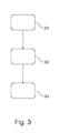
- Fig. 3 shows schematically and exemplarily an embodiment of a method for providing an airfoil portion 1 with a chamber 4 according to the invention. It comprises the following steps, not necessarily in this order: In step S1, providing an inner stiffening member 3, In step S2, providing an outer skin member 2, and In step S3, arranging the inner stiffening member 3 and/or the outer skin member 2 to delimit a chamber 4.
- the chamber 4 is configured to contain an inner pressure, and the inner pressure differs from a pressure external to the chamber 4.
- the chamber 4 is provided in the airfoil portion 1 without the need for additional separate parts.
- the outer skin member 2 and/or the inner stiffening member 3 as system parts are also used as structural parts. This double use allows reducing weight, costs and manufacturing effort for such airfoil portion 1 with a chamber 4.
Landscapes
- Engineering & Computer Science (AREA)
- Aviation & Aerospace Engineering (AREA)
- Mechanical Engineering (AREA)
- Turbine Rotor Nozzle Sealing (AREA)
Abstract
Description
- The invention relates to an airfoil portion with a chamber or plenum, an aircraft comprising such airfoil portion, and a method for providing such airfoil portion with such chamber or plenum.
- A chamber or plenum can be a pressurized housing containing a gas or fluid (typically air) at a pressure different from the surroundings. Such plenums can be arranged at an airfoil portion of an aircraft to improve the airfoil's flight properties, as e.g. to impose homogeneity in air flows. Conventionally, such plenums are made from parts separate the airfoil portion, as e.g. tubes, pipes, etc. Such additional parts, however, increase the weight, the costs and the manufacture effort for an airfoil portion with a plenum.
- Hence, there may be a need to provide a lighter airfoil portion with a chamber.
- The problem of the present invention is solved by the subject-matters of the independent claims, wherein further embodiments are incorporated in the dependent claims. It should be noted that the aspects of the invention described in the following apply also to the airfoil portion, the aircraft comprising such airfoil portion, and the method for providing such airfoil portion with a chamber.
- According to the present invention, an airfoil portion is presented. The airfoil portion comprises an outer skin member and an inner stiffening member. Either the outer skin member or the inner stiffening member or both are arranged to delimit a chamber. The chamber is configured to contain an inner pressure, wherein the inner pressure differs from a pressure external to the chamber.
- As a result, the chamber is provided in the airfoil portion without the need for additional separate parts. The chamber is formed only by parts of the airfoil portion, as the outer skin member and/or the inner stiffening member. In other words, there is a double use of parts of the airfoil portion as first, the outer skin member and/or the inner stiffening member, and second, as components forming the chamber. Thereby, the outer skin member and/or the inner stiffening member as system parts are also used as structural parts. This double use allows reducing weight, costs and manufacturing effort for such airfoil portion with a chamber.
- The inner pressure may be an overpressure or underpressure of gas or fluid (typically air) relative to the pressure external to the chamber. The overpressure may allow e.g. a greater stability to aerodynamic loads, a better protection to bird strike and so on.
- The inner stiffening member may be at least one spar, rib and sandwich or the like or combinations thereof. In an example, the inner stiffening member is a front spar configured to provide a structural stability to the airfoil portion. In another example, the inner stiffening member is a mounting spar configured to hold a mechanical and/or electric subsystem of the aircraft. In a further example, the inner stiffening member is a combination spar configured to provide a structural stability to the airfoil portion and to hold a mechanical and/or electric subsystem of the aircraft. This multiple use of the combination spar allows further reducing weight, costs and manufacturing effort.
- In an example, the chamber extends between the inner stiffening member, a leading edge, a portion of an upper surface, and a portion of a lower surface of the airfoil portion. The usage of this space between the inner stiffening member and the leading edge as chamber and e.g. overpressure plenum is beneficial in terms of structural stability. If the chamber is formed by the leading edge, the chamber provides an improved separation control. In another example, the chamber extends between the inner stiffening member, a trailing edge, a portion of an upper surface, and a portion of a lower surface of the airfoil portion. In a further example, the chamber extends between the front spar as inner stiffening member, a rear spar, a portion of an upper surface, and a portion of a lower surface of the airfoil portion. From an aerodynamic point of view, the chamber is preferably as large as possible to ensure a low-friction flow.
- The chamber may be a plenum. The plenum may comprise a volume in the airfoil extending between the outer skin member and the inner stiffening member. The maximum plenum volume may be optimal for any application reasoned by minimizing dynamic pressure associated with pressure losses. The term "optimal" has to be understood as follows: the larger the plenum's cross-section, the smaller the flow velocity, the smaller the friction losses depending on the dynamic pressure, the smaller the pressure losses, the better the pressure's homogeneity in the direction of the plenum, which means that the maximum plenum volume is optimal.
- The inner pressure in the plenum relative to the plenum exterior has a slight over or underpressure to ensure effectiveness with respect to the desired application (suction and blowing). The exact value of the inner pressure may depend on the intended application of the airfoil portion and in particular on its profile, flight phase, position at the aircraft and the like. The exact value of the inner pressure may depend on the structural integrity.
- In an example, the airfoil portion further comprises at least one aperture configured for a passing of air in or out the chamber. The aperture may be of any type, as e.g. slots and holes in the upper surface or the lower surface of the airfoil portion. The aperture may be located at any position of the airfoil. The aperture may be configured for a passing of air into in terms of suction or out of the chamber in terms of blowing.
- In an example, the airfoil portion further comprises a flow control system and in particular an active flow control system configured to provide an air flow relative to a surface of the airfoil portion. The air flow relative to the surface of the airfoil portion may be along the surface, orthogonal, tangential or combinations thereof.
- Such flow control system may comprise at least a fluid actuator and may be utilized, e.g., in order to prevent flows from separating or detaching from the airfoil portion or from another flow body, or to reattach a flow that has already detached or separated from the airfoil portion or other flow body. The flow control system may be also configured to provide boundary layer suction to inhale the detaching or detached boundary layer or to prevent laminar turbulent transition.
- At least parts of the flow control system may be mounted to the inner stiffening member. Thereby, structural stability and protection against e.g. bird strike is provided. These parts of the flow control system can also be used as load carrying structure. This double use of the flow control system to provide flow control and to provide structural stability allows further reducing weight, costs and manufacturing effort.
- Air for the chamber and/or for the flow control system may be provided by an aircraft's engine or by an air intake at the airfoil portion.
- The airfoil may be a flap, a wing, a winglet, a tail plane, a slat, a tap, a control surface, a mounting surface, and/or a fuselage portion. If the chamber is formed by the leading edge of a wing portion as airfoil portion, the chamber provides an improved hybrid laminar flow control.
- According to the present invention, also an aircraft is presented. The aircraft comprises an airfoil portion as described above. The airfoil portion comprises again an outer skin member and an inner stiffening member. The outer skin member and/or the inner stiffening member are arranged to delimit a chamber. The chamber is configured to contain an inner pressure, wherein the inner pressure differs from a pressure external to the chamber.
- According to the present invention, also a method for providing an airfoil portion with a chamber is presented. It comprises the following steps, not necessarily in this order:
- a) providing an inner stiffening member,
- b) providing an outer skin member, and
- c) arranging the inner stiffening member and/or the outer skin member to delimit a chamber.
- The chamber is configured to contain an inner pressure, and the inner pressure differs from a pressure external to the chamber. As a result, the chamber is provided in the airfoil portion without the need for additional separate parts. In other words, there is a double use of parts of the airfoil portion as first, the outer skin member and/or the inner stiffening member, and second, as components forming the chamber.
- It shall be understood the airfoil portion, the aircraft comprising such airfoil portion, and the method for providing such airfoil portion with a chamber according to the independent claims have similar and/or identical preferred embodiments, in particular, as defined in the dependent claims. It shall be understood further that a preferred embodiment of the invention can also be any combination of the dependent claims with the respective independent claim.
- These and other aspects of the present invention will become apparent from and be elucidated with reference to the embodiments described hereinafter.
- Exemplary embodiments of the invention will be described in the following with reference to the accompanying drawings:
- Fig. 1
- shows schematically and exemplarily an embodiment of an airfoil portion according to the invention.
- Fig. 2
- shows schematically and exemplarily an embodiment of an
aircraft 7 according to the invention. - Fig. 3
- shows schematically and exemplarily an embodiment of a method for providing an airfoil portion with a chamber according to the invention.
-
Fig. 1 shows schematically and exemplarily an embodiment of anairfoil portion 1 according to the invention. The airfoil is here a flap. Theairfoil portion 1 comprises anouter skin member 2 and an inner stiffening member 3. Here, theouter skin member 2 and the inner stiffening member 3 are arranged to delimit achamber 4. Thechamber 4 is configured to contain an inner pressure, wherein the inner pressure differs from a pressure external to thechamber 4. In this example, thechamber 4 is configured to contain an overpressure relative to the surroundings. - Here, the inner pressure is e.g. an about 0.5 bar overpressure relative to the pressure external to the
chamber 4. Thechamber 4 is a plenum. It extends between a nose of aleading edge 21, a portion of anupper surface 22, and a portion of alower surface 23 of theouter skin member 2 and the inner stiffening member 3. Thechamber 4 comprises anaperture 5 for a passing of air in or out thechamber 4 as shown by the arrow. Theaperture 5 is here an outlet jet sleeve in theupper surface 22 of theairfoil portion 1. Theaperture 5 can, however, also be any other kind of opening and can also be arranged elsewhere in thechamber 4. - The inner stiffening member 3 is here at least a Z-shaped spar and in particular a combination spar of a front spar providing a structural stability to the
airfoil portion 1 and a mounting spar holding a flow control system. - The
airfoil portion 1 further comprises an activeflow control system 6 to provide an air flow along the surface of theairfoil portion 1. The flow control system comprises a so-called two stage fluidic actuator system with anactuator stage 61 and acontrol stage 62 for influencing an air flow relative to the surface. Theactuator stage 61 and thecontrol stage 62 are here separated by acover panel 63. Theactuator stage 61 is mounted to the inner stiffening member 3. Thecover panel 63 and thecontrol stage 62 are mounted to theactuator stage 61. These parts of the flow control system form a load carrying structure. -
Fig. 2 shows schematically and exemplarily an embodiment of anaircraft 7 according to the invention. Theaircraft 7 comprises anairfoil portion 1 as described above. The airfoil is here a wing. Theairfoil portion 1 comprises again anouter skin member 2 and an inner stiffening member 3 (not shown). Here, theouter skin member 2 and the inner stiffening member 3 are arranged to delimit a chamber 4 (not shown). Thechamber 4 is configured to contain an inner pressure, wherein the inner pressure differs from a pressure external to thechamber 4. -
Fig. 3 shows schematically and exemplarily an embodiment of a method for providing anairfoil portion 1 with achamber 4 according to the invention. It comprises the following steps, not necessarily in this order:In step S1, providing an inner stiffening member 3, In step S2, providing an outer skin member 2, andIn step S3, arranging the inner stiffening member 3 and/or the outer skin member 2 to delimit achamber 4. - The
chamber 4 is configured to contain an inner pressure, and the inner pressure differs from a pressure external to thechamber 4. As a result, thechamber 4 is provided in theairfoil portion 1 without the need for additional separate parts. Thereby, theouter skin member 2 and/or the inner stiffening member 3 as system parts are also used as structural parts. This double use allows reducing weight, costs and manufacturing effort forsuch airfoil portion 1 with achamber 4. - While the invention has been illustrated and described in detail in the drawings and foregoing description, such illustration and description are to be considered illustrative or exemplary and not restrictive. The invention is not limited to the disclosed embodiments. Other variations to the disclosed embodiments can be understood and effected by those skilled in the art in practicing a claimed invention, from a study of the drawings, the disclosure, and the dependent claims.
- In the claims, the word "comprising" does not exclude other elements or steps, and the indefinite article "a" or "an" does not exclude a plurality. A single processor or other unit may fulfil the functions of several items re-cited in the claims. The mere fact that certain measures are re-cited in mutually different dependent claims does not indicate that a combination of these measures cannot be used to advantage. Any reference signs in the claims should not be construed as limiting the scope.
Claims (15)
- An airfoil portion (1), comprising
an outer skin member (2), and
an inner stiffening member (3),
wherein the outer skin member (2) and/or the inner stiffening member (3) are arranged to delimit a chamber (4),
wherein the chamber (4) is configured to contain an inner pressure, and wherein the inner pressure differs from a pressure external to the chamber (4). - Airfoil portion (1) according to claim 1, wherein the chamber (4) is a plenum and wherein the inner pressure is an overpressure or underpressure relative to the pressure external to the chamber (4).
- Airfoil portion (1) according to claim 1, wherein the inner stiffening member (3) is a front spar configured to provide a structural stability to the airfoil portion (1).
- Airfoil portion (1) according to claim 1, wherein the inner stiffening member (3) is a mounting spar configured to hold a mechanical and/or electric subsystem of the aircraft (7).
- Airfoil portion (1) according to claim 1, wherein the inner stiffening member (3) is a combination spar configured to provide a structural stability to the airfoil portion (1) and to hold a mechanical and/or electric subsystem of the aircraft (7).
- Airfoil portion (1) according to one of the preceding claims, wherein the chamber (4) extends between the inner stiffening member (3), a leading edge (21), a portion of an upper surface (22), and a portion of a lower surface (23) of the airfoil portion (1).
- Airfoil portion (1) according to one of the claims 1 to 5, wherein the chamber (4) extends between the inner stiffening member (3), a trailing edge, a portion of an upper surface (22), and a portion of a lower surface (23) of the airfoil portion (1).
- Airfoil portion (1) according to one of the claims 1 to 5, wherein the chamber (4) extends between the front spar as inner stiffening member (3), a rear spar, a portion of an upper surface (22), and a portion of a lower surface (23) of the airfoil portion (1).
- Airfoil portion (1) according to one of the preceding claims, further comprising at least one aperture configured for a passing of air in or out the chamber (4).
- Airfoil portion (1) according to one of the preceding claims, further comprising a flow control system configured to provide an air flow relative to a surface of the airfoil portion (1).
- Airfoil portion (1) according to the preceding claim, wherein at least parts of the flow control system are mounted to the inner stiffening member (3).
- Airfoil portion (1) according to one of the preceding claims, wherein air for the chamber (4) and/or for the flow control system is provided by an air intake at the airfoil portion (1).
- Airfoil portion (1) according to one of the preceding claims, wherein the airfoil portion (1) is a portion of a flap, a wing, a winglet, a tail plane, a slat, a tap, a control surface, a mounting surface, and/or a fuselage portion.
- An aircraft (7) comprising an airfoil portion (1) according to one of the preceding claims.
- A method for providing an airfoil portion (1) with a chamber (4), comprising the following steps:- providing an inner stiffening member (3),- providing an outer skin member (2), and- arranging the inner stiffening member (3) and/or the outer skin member (2) to delimit a chamber (4),wherein the chamber (4) is configured to contain an inner pressure, and wherein the inner pressure differs from a pressure external to the chamber (4).
Priority Applications (2)
| Application Number | Priority Date | Filing Date | Title |
|---|---|---|---|
| EP14184074.4A EP2995552B1 (en) | 2014-09-09 | 2014-09-09 | Chamber in an airfoil |
| US14/841,817 US9963219B2 (en) | 2014-09-09 | 2015-09-01 | Airfoil portion with a chamber |
Applications Claiming Priority (1)
| Application Number | Priority Date | Filing Date | Title |
|---|---|---|---|
| EP14184074.4A EP2995552B1 (en) | 2014-09-09 | 2014-09-09 | Chamber in an airfoil |
Publications (2)
| Publication Number | Publication Date |
|---|---|
| EP2995552A1 true EP2995552A1 (en) | 2016-03-16 |
| EP2995552B1 EP2995552B1 (en) | 2018-05-02 |
Family
ID=51494159
Family Applications (1)
| Application Number | Title | Priority Date | Filing Date |
|---|---|---|---|
| EP14184074.4A Active EP2995552B1 (en) | 2014-09-09 | 2014-09-09 | Chamber in an airfoil |
Country Status (2)
| Country | Link |
|---|---|
| US (1) | US9963219B2 (en) |
| EP (1) | EP2995552B1 (en) |
Cited By (2)
| Publication number | Priority date | Publication date | Assignee | Title |
|---|---|---|---|---|
| WO2020148665A1 (en) | 2019-01-15 | 2020-07-23 | Lumus Ltd. | Method of fabricating a symmetric light guide optical element |
| WO2025229479A1 (en) | 2024-04-29 | 2025-11-06 | Leonardo S.P.A. | Leading edge system for an aircraft, provided with an assembly for absorbing impacts |
Families Citing this family (4)
| Publication number | Priority date | Publication date | Assignee | Title |
|---|---|---|---|---|
| US9896190B1 (en) * | 2014-05-07 | 2018-02-20 | The Boeing Company | Wing leading edge architecture suitable for laminar flow |
| GB2557274A (en) * | 2016-12-02 | 2018-06-20 | Airbus Operations Ltd | Aerofoil structure components |
| ES2927476T3 (en) * | 2017-10-09 | 2022-11-07 | Airbus Operations Gmbh | Vertical tail unit for flow control |
| EP3466811B1 (en) * | 2017-10-09 | 2023-06-21 | Airbus Operations GmbH | Vertical tail unit for flow control |
Citations (6)
| Publication number | Priority date | Publication date | Assignee | Title |
|---|---|---|---|---|
| US1988670A (en) * | 1929-12-13 | 1935-01-22 | Edward A Stalker | Wing construction |
| US2223744A (en) * | 1938-01-24 | 1940-12-03 | Edward A Stalker | Wing and similar construction |
| DE723570C (en) * | 1938-06-08 | 1942-08-06 | Messerschmitt Boelkow Blohm | Aircraft structure provided with devices for influencing the flow boundary layer |
| US2946540A (en) * | 1948-09-13 | 1960-07-26 | Sebac Nouvelle Sa | Jet propelled aircraft |
| US5806808A (en) * | 1995-05-19 | 1998-09-15 | Mcdonnell Douglas Corp. | Airfoil lift management device |
| FR2924407A1 (en) * | 2007-12-03 | 2009-06-05 | Airbus France Sas | AIR EXIT SYSTEM FOR AN AIRCRAFT ATTACK RIM |
Family Cites Families (1)
| Publication number | Priority date | Publication date | Assignee | Title |
|---|---|---|---|---|
| US2928627A (en) * | 1956-07-10 | 1960-03-15 | Lockheed Aircraft Corp | Aircraft propulsion systems |
-
2014
- 2014-09-09 EP EP14184074.4A patent/EP2995552B1/en active Active
-
2015
- 2015-09-01 US US14/841,817 patent/US9963219B2/en active Active
Patent Citations (6)
| Publication number | Priority date | Publication date | Assignee | Title |
|---|---|---|---|---|
| US1988670A (en) * | 1929-12-13 | 1935-01-22 | Edward A Stalker | Wing construction |
| US2223744A (en) * | 1938-01-24 | 1940-12-03 | Edward A Stalker | Wing and similar construction |
| DE723570C (en) * | 1938-06-08 | 1942-08-06 | Messerschmitt Boelkow Blohm | Aircraft structure provided with devices for influencing the flow boundary layer |
| US2946540A (en) * | 1948-09-13 | 1960-07-26 | Sebac Nouvelle Sa | Jet propelled aircraft |
| US5806808A (en) * | 1995-05-19 | 1998-09-15 | Mcdonnell Douglas Corp. | Airfoil lift management device |
| FR2924407A1 (en) * | 2007-12-03 | 2009-06-05 | Airbus France Sas | AIR EXIT SYSTEM FOR AN AIRCRAFT ATTACK RIM |
Cited By (2)
| Publication number | Priority date | Publication date | Assignee | Title |
|---|---|---|---|---|
| WO2020148665A1 (en) | 2019-01-15 | 2020-07-23 | Lumus Ltd. | Method of fabricating a symmetric light guide optical element |
| WO2025229479A1 (en) | 2024-04-29 | 2025-11-06 | Leonardo S.P.A. | Leading edge system for an aircraft, provided with an assembly for absorbing impacts |
Also Published As
| Publication number | Publication date |
|---|---|
| US9963219B2 (en) | 2018-05-08 |
| US20160068250A1 (en) | 2016-03-10 |
| EP2995552B1 (en) | 2018-05-02 |
Similar Documents
| Publication | Publication Date | Title |
|---|---|---|
| EP2995552B1 (en) | Chamber in an airfoil | |
| US7866609B2 (en) | Passive removal of suction air for laminar flow control, and associated systems and methods | |
| EP3031713B1 (en) | Aircraft wing rib | |
| US9623959B2 (en) | Aircraft having an aircraft fuselage and an air sucking fuselage component | |
| CN107021207B (en) | Aircraft flow device for passive boundary layer suction | |
| US20190092456A1 (en) | Ducts for laminar flow control systems | |
| EP3552958B1 (en) | Optimized nacelle profile and plenum shape for boundary layer ingestion active laminar flow control | |
| US20160068270A1 (en) | Air generation unit for an aircraft | |
| US11155342B2 (en) | Leading edge structure for a flow control system of an aircraft | |
| CN104590569B (en) | Helicopter with engine intake | |
| US11208202B2 (en) | Flow body of an aircraft and aircraft | |
| US11453481B2 (en) | Aerofoil leading edge structures | |
| US10144525B2 (en) | Aircraft engine pylon to wing mounting assembly | |
| US9487287B2 (en) | Wing leading edge venting | |
| US20070228222A1 (en) | Method of improving lift of an aircraft wing | |
| US11299253B2 (en) | Transonic airfoil, wing, and aircraft | |
| ES2777280T3 (en) | Leading edge with laminar flow control | |
| Grek et al. | Hydrodynamic instability of boundary layers and separated flows (present state) |
Legal Events
| Date | Code | Title | Description |
|---|---|---|---|
| PUAI | Public reference made under article 153(3) epc to a published international application that has entered the european phase |
Free format text: ORIGINAL CODE: 0009012 |
|
| AK | Designated contracting states |
Kind code of ref document: A1 Designated state(s): AL AT BE BG CH CY CZ DE DK EE ES FI FR GB GR HR HU IE IS IT LI LT LU LV MC MK MT NL NO PL PT RO RS SE SI SK SM TR |
|
| AX | Request for extension of the european patent |
Extension state: BA ME |
|
| 17P | Request for examination filed |
Effective date: 20160916 |
|
| RBV | Designated contracting states (corrected) |
Designated state(s): AL AT BE BG CH CY CZ DE DK EE ES FI FR GB GR HR HU IE IS IT LI LT LU LV MC MK MT NL NO PL PT RO RS SE SI SK SM TR |
|
| STAA | Information on the status of an ep patent application or granted ep patent |
Free format text: STATUS: EXAMINATION IS IN PROGRESS |
|
| 17Q | First examination report despatched |
Effective date: 20170526 |
|
| REG | Reference to a national code |
Ref country code: DE Ref legal event code: R079 Ref document number: 602014024767 Country of ref document: DE Free format text: PREVIOUS MAIN CLASS: B64C0003140000 Ipc: B64C0003260000 |
|
| GRAP | Despatch of communication of intention to grant a patent |
Free format text: ORIGINAL CODE: EPIDOSNIGR1 |
|
| STAA | Information on the status of an ep patent application or granted ep patent |
Free format text: STATUS: GRANT OF PATENT IS INTENDED |
|
| RIC1 | Information provided on ipc code assigned before grant |
Ipc: B64C 3/14 20060101ALI20171107BHEP Ipc: B64C 9/14 20060101ALI20171107BHEP Ipc: B64C 3/26 20060101AFI20171107BHEP Ipc: B64C 3/18 20060101ALI20171107BHEP Ipc: B64C 21/02 20060101ALI20171107BHEP |
|
| INTG | Intention to grant announced |
Effective date: 20171212 |
|
| RIN1 | Information on inventor provided before grant (corrected) |
Inventor name: LENGERS, MATTHIAS Inventor name: MEYER, MICHAEL Inventor name: MACHUNZE, WOLFGANG |
|
| GRAS | Grant fee paid |
Free format text: ORIGINAL CODE: EPIDOSNIGR3 |
|
| GRAA | (expected) grant |
Free format text: ORIGINAL CODE: 0009210 |
|
| STAA | Information on the status of an ep patent application or granted ep patent |
Free format text: STATUS: THE PATENT HAS BEEN GRANTED |
|
| RIN1 | Information on inventor provided before grant (corrected) |
Inventor name: MACHUNZE, WOLFGANG Inventor name: LENGERS, MATTHIAS Inventor name: MEYER, MICHAEL |
|
| AK | Designated contracting states |
Kind code of ref document: B1 Designated state(s): AL AT BE BG CH CY CZ DE DK EE ES FI FR GB GR HR HU IE IS IT LI LT LU LV MC MK MT NL NO PL PT RO RS SE SI SK SM TR |
|
| RAP1 | Party data changed (applicant data changed or rights of an application transferred) |
Owner name: AIRBUS DEFENCE AND SPACE GMBH Owner name: AIRBUS OPERATIONS GMBH |
|
| REG | Reference to a national code |
Ref country code: GB Ref legal event code: FG4D |
|
| REG | Reference to a national code |
Ref country code: CH Ref legal event code: EP Ref country code: AT Ref legal event code: REF Ref document number: 994937 Country of ref document: AT Kind code of ref document: T Effective date: 20180515 |
|
| REG | Reference to a national code |
Ref country code: DE Ref legal event code: R096 Ref document number: 602014024767 Country of ref document: DE Ref country code: IE Ref legal event code: FG4D |
|
| REG | Reference to a national code |
Ref country code: NL Ref legal event code: MP Effective date: 20180502 |
|
| REG | Reference to a national code |
Ref country code: LT Ref legal event code: MG4D Ref country code: FR Ref legal event code: PLFP Year of fee payment: 5 |
|
| PG25 | Lapsed in a contracting state [announced via postgrant information from national office to epo] |
Ref country code: ES Free format text: LAPSE BECAUSE OF FAILURE TO SUBMIT A TRANSLATION OF THE DESCRIPTION OR TO PAY THE FEE WITHIN THE PRESCRIBED TIME-LIMIT Effective date: 20180502 Ref country code: LT Free format text: LAPSE BECAUSE OF FAILURE TO SUBMIT A TRANSLATION OF THE DESCRIPTION OR TO PAY THE FEE WITHIN THE PRESCRIBED TIME-LIMIT Effective date: 20180502 Ref country code: NO Free format text: LAPSE BECAUSE OF FAILURE TO SUBMIT A TRANSLATION OF THE DESCRIPTION OR TO PAY THE FEE WITHIN THE PRESCRIBED TIME-LIMIT Effective date: 20180802 Ref country code: BG Free format text: LAPSE BECAUSE OF FAILURE TO SUBMIT A TRANSLATION OF THE DESCRIPTION OR TO PAY THE FEE WITHIN THE PRESCRIBED TIME-LIMIT Effective date: 20180802 Ref country code: SE Free format text: LAPSE BECAUSE OF FAILURE TO SUBMIT A TRANSLATION OF THE DESCRIPTION OR TO PAY THE FEE WITHIN THE PRESCRIBED TIME-LIMIT Effective date: 20180502 Ref country code: FI Free format text: LAPSE BECAUSE OF FAILURE TO SUBMIT A TRANSLATION OF THE DESCRIPTION OR TO PAY THE FEE WITHIN THE PRESCRIBED TIME-LIMIT Effective date: 20180502 |
|
| PG25 | Lapsed in a contracting state [announced via postgrant information from national office to epo] |
Ref country code: GR Free format text: LAPSE BECAUSE OF FAILURE TO SUBMIT A TRANSLATION OF THE DESCRIPTION OR TO PAY THE FEE WITHIN THE PRESCRIBED TIME-LIMIT Effective date: 20180803 Ref country code: RS Free format text: LAPSE BECAUSE OF FAILURE TO SUBMIT A TRANSLATION OF THE DESCRIPTION OR TO PAY THE FEE WITHIN THE PRESCRIBED TIME-LIMIT Effective date: 20180502 Ref country code: LV Free format text: LAPSE BECAUSE OF FAILURE TO SUBMIT A TRANSLATION OF THE DESCRIPTION OR TO PAY THE FEE WITHIN THE PRESCRIBED TIME-LIMIT Effective date: 20180502 Ref country code: NL Free format text: LAPSE BECAUSE OF FAILURE TO SUBMIT A TRANSLATION OF THE DESCRIPTION OR TO PAY THE FEE WITHIN THE PRESCRIBED TIME-LIMIT Effective date: 20180502 Ref country code: HR Free format text: LAPSE BECAUSE OF FAILURE TO SUBMIT A TRANSLATION OF THE DESCRIPTION OR TO PAY THE FEE WITHIN THE PRESCRIBED TIME-LIMIT Effective date: 20180502 |
|
| REG | Reference to a national code |
Ref country code: AT Ref legal event code: MK05 Ref document number: 994937 Country of ref document: AT Kind code of ref document: T Effective date: 20180502 |
|
| PG25 | Lapsed in a contracting state [announced via postgrant information from national office to epo] |
Ref country code: RO Free format text: LAPSE BECAUSE OF FAILURE TO SUBMIT A TRANSLATION OF THE DESCRIPTION OR TO PAY THE FEE WITHIN THE PRESCRIBED TIME-LIMIT Effective date: 20180502 Ref country code: CZ Free format text: LAPSE BECAUSE OF FAILURE TO SUBMIT A TRANSLATION OF THE DESCRIPTION OR TO PAY THE FEE WITHIN THE PRESCRIBED TIME-LIMIT Effective date: 20180502 Ref country code: SK Free format text: LAPSE BECAUSE OF FAILURE TO SUBMIT A TRANSLATION OF THE DESCRIPTION OR TO PAY THE FEE WITHIN THE PRESCRIBED TIME-LIMIT Effective date: 20180502 Ref country code: AT Free format text: LAPSE BECAUSE OF FAILURE TO SUBMIT A TRANSLATION OF THE DESCRIPTION OR TO PAY THE FEE WITHIN THE PRESCRIBED TIME-LIMIT Effective date: 20180502 Ref country code: PL Free format text: LAPSE BECAUSE OF FAILURE TO SUBMIT A TRANSLATION OF THE DESCRIPTION OR TO PAY THE FEE WITHIN THE PRESCRIBED TIME-LIMIT Effective date: 20180502 Ref country code: DK Free format text: LAPSE BECAUSE OF FAILURE TO SUBMIT A TRANSLATION OF THE DESCRIPTION OR TO PAY THE FEE WITHIN THE PRESCRIBED TIME-LIMIT Effective date: 20180502 Ref country code: EE Free format text: LAPSE BECAUSE OF FAILURE TO SUBMIT A TRANSLATION OF THE DESCRIPTION OR TO PAY THE FEE WITHIN THE PRESCRIBED TIME-LIMIT Effective date: 20180502 |
|
| REG | Reference to a national code |
Ref country code: DE Ref legal event code: R097 Ref document number: 602014024767 Country of ref document: DE |
|
| PG25 | Lapsed in a contracting state [announced via postgrant information from national office to epo] |
Ref country code: SM Free format text: LAPSE BECAUSE OF FAILURE TO SUBMIT A TRANSLATION OF THE DESCRIPTION OR TO PAY THE FEE WITHIN THE PRESCRIBED TIME-LIMIT Effective date: 20180502 Ref country code: IT Free format text: LAPSE BECAUSE OF FAILURE TO SUBMIT A TRANSLATION OF THE DESCRIPTION OR TO PAY THE FEE WITHIN THE PRESCRIBED TIME-LIMIT Effective date: 20180502 |
|
| PLBE | No opposition filed within time limit |
Free format text: ORIGINAL CODE: 0009261 |
|
| STAA | Information on the status of an ep patent application or granted ep patent |
Free format text: STATUS: NO OPPOSITION FILED WITHIN TIME LIMIT |
|
| 26N | No opposition filed |
Effective date: 20190205 |
|
| PG25 | Lapsed in a contracting state [announced via postgrant information from national office to epo] |
Ref country code: MC Free format text: LAPSE BECAUSE OF FAILURE TO SUBMIT A TRANSLATION OF THE DESCRIPTION OR TO PAY THE FEE WITHIN THE PRESCRIBED TIME-LIMIT Effective date: 20180502 |
|
| REG | Reference to a national code |
Ref country code: CH Ref legal event code: PL |
|
| PG25 | Lapsed in a contracting state [announced via postgrant information from national office to epo] |
Ref country code: SI Free format text: LAPSE BECAUSE OF FAILURE TO SUBMIT A TRANSLATION OF THE DESCRIPTION OR TO PAY THE FEE WITHIN THE PRESCRIBED TIME-LIMIT Effective date: 20180502 |
|
| REG | Reference to a national code |
Ref country code: IE Ref legal event code: MM4A |
|
| PG25 | Lapsed in a contracting state [announced via postgrant information from national office to epo] |
Ref country code: LU Free format text: LAPSE BECAUSE OF NON-PAYMENT OF DUE FEES Effective date: 20180909 |
|
| PG25 | Lapsed in a contracting state [announced via postgrant information from national office to epo] |
Ref country code: IE Free format text: LAPSE BECAUSE OF NON-PAYMENT OF DUE FEES Effective date: 20180909 |
|
| PG25 | Lapsed in a contracting state [announced via postgrant information from national office to epo] |
Ref country code: LI Free format text: LAPSE BECAUSE OF NON-PAYMENT OF DUE FEES Effective date: 20180930 Ref country code: CH Free format text: LAPSE BECAUSE OF NON-PAYMENT OF DUE FEES Effective date: 20180930 |
|
| PGFP | Annual fee paid to national office [announced via postgrant information from national office to epo] |
Ref country code: FR Payment date: 20190927 Year of fee payment: 6 |
|
| PG25 | Lapsed in a contracting state [announced via postgrant information from national office to epo] |
Ref country code: AL Free format text: LAPSE BECAUSE OF FAILURE TO SUBMIT A TRANSLATION OF THE DESCRIPTION OR TO PAY THE FEE WITHIN THE PRESCRIBED TIME-LIMIT Effective date: 20180502 |
|
| PGFP | Annual fee paid to national office [announced via postgrant information from national office to epo] |
Ref country code: BE Payment date: 20190918 Year of fee payment: 6 |
|
| PG25 | Lapsed in a contracting state [announced via postgrant information from national office to epo] |
Ref country code: MT Free format text: LAPSE BECAUSE OF NON-PAYMENT OF DUE FEES Effective date: 20180909 |
|
| PG25 | Lapsed in a contracting state [announced via postgrant information from national office to epo] |
Ref country code: TR Free format text: LAPSE BECAUSE OF FAILURE TO SUBMIT A TRANSLATION OF THE DESCRIPTION OR TO PAY THE FEE WITHIN THE PRESCRIBED TIME-LIMIT Effective date: 20180502 |
|
| PG25 | Lapsed in a contracting state [announced via postgrant information from national office to epo] |
Ref country code: PT Free format text: LAPSE BECAUSE OF FAILURE TO SUBMIT A TRANSLATION OF THE DESCRIPTION OR TO PAY THE FEE WITHIN THE PRESCRIBED TIME-LIMIT Effective date: 20180502 |
|
| PG25 | Lapsed in a contracting state [announced via postgrant information from national office to epo] |
Ref country code: MK Free format text: LAPSE BECAUSE OF NON-PAYMENT OF DUE FEES Effective date: 20180502 Ref country code: HU Free format text: LAPSE BECAUSE OF FAILURE TO SUBMIT A TRANSLATION OF THE DESCRIPTION OR TO PAY THE FEE WITHIN THE PRESCRIBED TIME-LIMIT; INVALID AB INITIO Effective date: 20140909 Ref country code: CY Free format text: LAPSE BECAUSE OF FAILURE TO SUBMIT A TRANSLATION OF THE DESCRIPTION OR TO PAY THE FEE WITHIN THE PRESCRIBED TIME-LIMIT Effective date: 20180502 |
|
| PG25 | Lapsed in a contracting state [announced via postgrant information from national office to epo] |
Ref country code: IS Free format text: LAPSE BECAUSE OF FAILURE TO SUBMIT A TRANSLATION OF THE DESCRIPTION OR TO PAY THE FEE WITHIN THE PRESCRIBED TIME-LIMIT Effective date: 20180902 |
|
| REG | Reference to a national code |
Ref country code: BE Ref legal event code: MM Effective date: 20200930 |
|
| PG25 | Lapsed in a contracting state [announced via postgrant information from national office to epo] |
Ref country code: FR Free format text: LAPSE BECAUSE OF NON-PAYMENT OF DUE FEES Effective date: 20200930 |
|
| PG25 | Lapsed in a contracting state [announced via postgrant information from national office to epo] |
Ref country code: BE Free format text: LAPSE BECAUSE OF NON-PAYMENT OF DUE FEES Effective date: 20200930 |
|
| PGFP | Annual fee paid to national office [announced via postgrant information from national office to epo] |
Ref country code: DE Payment date: 20240918 Year of fee payment: 11 |
|
| PGFP | Annual fee paid to national office [announced via postgrant information from national office to epo] |
Ref country code: GB Payment date: 20250919 Year of fee payment: 12 |