EP2995256A1 - Cable assembly for converting a consecutive signaling arrangement to an interleaved signaling arrangement - Google Patents
Cable assembly for converting a consecutive signaling arrangement to an interleaved signaling arrangement Download PDFInfo
- Publication number
- EP2995256A1 EP2995256A1 EP15183938.8A EP15183938A EP2995256A1 EP 2995256 A1 EP2995256 A1 EP 2995256A1 EP 15183938 A EP15183938 A EP 15183938A EP 2995256 A1 EP2995256 A1 EP 2995256A1
- Authority
- EP
- European Patent Office
- Prior art keywords
- wires
- group
- distance
- electrical contacts
- cable assembly
- Prior art date
- Legal status (The legal status is an assumption and is not a legal conclusion. Google has not performed a legal analysis and makes no representation as to the accuracy of the status listed.)
- Withdrawn
Links
- 230000011664 signaling Effects 0.000 title description 8
- 239000000523 sample Substances 0.000 claims description 36
- 238000002604 ultrasonography Methods 0.000 claims description 34
- 239000000463 material Substances 0.000 claims description 27
- 238000000034 method Methods 0.000 claims description 9
- 230000008878 coupling Effects 0.000 claims description 5
- 238000010168 coupling process Methods 0.000 claims description 5
- 238000005859 coupling reaction Methods 0.000 claims description 5
- 239000004020 conductor Substances 0.000 claims description 4
- 238000004519 manufacturing process Methods 0.000 claims description 3
- 239000000853 adhesive Substances 0.000 description 1
- 230000001070 adhesive effect Effects 0.000 description 1
- 238000001125 extrusion Methods 0.000 description 1
- 238000012986 modification Methods 0.000 description 1
- 230000004048 modification Effects 0.000 description 1
- 229920006267 polyester film Polymers 0.000 description 1
Images


Classifications
-
- A—HUMAN NECESSITIES
- A61—MEDICAL OR VETERINARY SCIENCE; HYGIENE
- A61B—DIAGNOSIS; SURGERY; IDENTIFICATION
- A61B8/00—Diagnosis using ultrasonic, sonic or infrasonic waves
- A61B8/56—Details of data transmission or power supply
-
- A—HUMAN NECESSITIES
- A61—MEDICAL OR VETERINARY SCIENCE; HYGIENE
- A61B—DIAGNOSIS; SURGERY; IDENTIFICATION
- A61B8/00—Diagnosis using ultrasonic, sonic or infrasonic waves
- A61B8/44—Constructional features of the ultrasonic, sonic or infrasonic diagnostic device
- A61B8/4444—Constructional features of the ultrasonic, sonic or infrasonic diagnostic device related to the probe
-
- A—HUMAN NECESSITIES
- A61—MEDICAL OR VETERINARY SCIENCE; HYGIENE
- A61B—DIAGNOSIS; SURGERY; IDENTIFICATION
- A61B8/00—Diagnosis using ultrasonic, sonic or infrasonic waves
- A61B8/44—Constructional features of the ultrasonic, sonic or infrasonic diagnostic device
- A61B8/4483—Constructional features of the ultrasonic, sonic or infrasonic diagnostic device characterised by features of the ultrasound transducer
-
- H—ELECTRICITY
- H01—ELECTRIC ELEMENTS
- H01B—CABLES; CONDUCTORS; INSULATORS; SELECTION OF MATERIALS FOR THEIR CONDUCTIVE, INSULATING OR DIELECTRIC PROPERTIES
- H01B13/00—Apparatus or processes specially adapted for manufacturing conductors or cables
- H01B13/06—Insulating conductors or cables
-
- H—ELECTRICITY
- H01—ELECTRIC ELEMENTS
- H01B—CABLES; CONDUCTORS; INSULATORS; SELECTION OF MATERIALS FOR THEIR CONDUCTIVE, INSULATING OR DIELECTRIC PROPERTIES
- H01B7/00—Insulated conductors or cables characterised by their form
- H01B7/009—Cables with built-in connecting points or with predetermined areas for making deviations
-
- A—HUMAN NECESSITIES
- A61—MEDICAL OR VETERINARY SCIENCE; HYGIENE
- A61B—DIAGNOSIS; SURGERY; IDENTIFICATION
- A61B8/00—Diagnosis using ultrasonic, sonic or infrasonic waves
- A61B8/52—Devices using data or image processing specially adapted for diagnosis using ultrasonic, sonic or infrasonic waves
- A61B8/5207—Devices using data or image processing specially adapted for diagnosis using ultrasonic, sonic or infrasonic waves involving processing of raw data to produce diagnostic data, e.g. for generating an image
-
- H—ELECTRICITY
- H01—ELECTRIC ELEMENTS
- H01B—CABLES; CONDUCTORS; INSULATORS; SELECTION OF MATERIALS FOR THEIR CONDUCTIVE, INSULATING OR DIELECTRIC PROPERTIES
- H01B7/00—Insulated conductors or cables characterised by their form
- H01B7/08—Flat or ribbon cables
-
- H—ELECTRICITY
- H01—ELECTRIC ELEMENTS
- H01R—ELECTRICALLY-CONDUCTIVE CONNECTIONS; STRUCTURAL ASSOCIATIONS OF A PLURALITY OF MUTUALLY-INSULATED ELECTRICAL CONNECTING ELEMENTS; COUPLING DEVICES; CURRENT COLLECTORS
- H01R31/00—Coupling parts supported only by co-operation with counterpart
- H01R31/06—Intermediate parts for linking two coupling parts, e.g. adapter
Definitions
- the present invention relates generally to a cabling arrangement for an ultrasound system. More specifically, the present invention relates to ribbon cable that facilitates coupling an ultrasound processor with a consecutive signaling arrangement to a probe that has an interleaved signaling arrangement.
- Many medical devices include a base unit and a remote unit where the remote unit communicates information to and from the base unit.
- the base unit then processes information communicated from the remote unit and provides diagnostic information, reports, and the like.
- a cable that includes a group of electrical wires couples the remote unit to the base unit.
- signals may be communicated between an ultrasound probe and an ultrasound processor over a cable that includes hundreds of wires.
- the wires within the cable may be provided in the form of a ribbon cable where conductors are arranged next to one another, side-by-side, and held together by a ribbonizing material, such as plastic.
- a ribbonizing material such as plastic.
- the respective ends of the ribbon cable are connected to the ultrasound probe and the ultrasound processor. Connection of the probe and processor is relatively easy when the pin out arrangements on the probe and processor match.
- the pins on the probe and processor may be configured so that half the pins are used for sending information to the transducers of the probe and the other half of the pins are used for receiving information from the transducers within the probe. In some ultrasound systems, this is accomplished by arranged the pins on the processor and probe so that a first group of adjacent pins is used to transmit transducer signals and a second group of adjacent pins is used to receive transducer signals. For example, pins 1-8 on both the probe and the processor may be used for sending transducer information, and pins 9-16 may be used for receiving transducer information.
- the pin out arrangement of the probe and the processor do not match.
- the pin out on the probe may be configured so that the function (i.e., receiving and sending) alternates between odd and even-numbered pins.
- pins one and three on the probe may be used for sending signals to transducers numbered one and two of the probe.
- Pins two and four may be used for receiving signals from the transducers numbered one and two, and so on.
- an operator typically has to peel individual wires out of the ribbon at one end or the other and re-arrange the wires so that the signals are communicated correctly.
- a cable assembly in one aspect, includes a first group of wires arranged side-by-side. At a first end, the wires are held in place relative to one another so that the wires are separated by a first distance; and at a second end, the wires are held in place relative to one another so that the wires are separated by a second distance that is greater than the first distance.
- the cable includes a second group of wires arranged side-by-side. At a first end, the second group of wires are held in place relative to one another so that they are separated by a third distance; and at a second end, the wires are held in place relative to one another so that they are separated by a fourth distance that is greater than the third distance.
- the first group of wires is overlaid or overlays on the second group of wires such that the first end of the first group of wires is adjacent to the first end of the second group of wires, and each wire of the second end of the first group of wires is interleaved with a wire of the second end of the second group of wires.
- a method for manufacturing a cable includes arranging a first group of wires side-by-side so that at a first end, the wires are separated by a first distance; and at a second end, the wires are separated by a second distance that is greater than the first distance.
- a ribbonizing material is applied over the first end and the second end of the first group of wires to hold the wires in place.
- the method also includes arranging a second group of wires side-by-side so that at a first end, the wires are separated by a third distance; and at a second end, the wires are separated by a fourth distance that is greater than the third distance.
- a ribbonizing material is applied over the first end and the second end of the second group of wires to hold the wires in place.
- the first group of wires is overlaid on the second group of wires such that the first end of the first group of wires is adjacent the first end of the second group of wires, and each wire of the second end of the first group of wires is interleaved with a wire of the second end of the second group of wires.
- an ultrasound system in a third aspect, includes an ultrasound probe, an ultrasound processor, and a cable assembly for communicating signals between the ultrasound probe and the ultrasound processor.
- the ultrasound probe has a first group of electrical contacts for sending transducer signals, and a second group of electrical contacts interleaved with the first group of electrical contacts for receiving transducer signals.
- the ultrasound processor has a first group of electrical contacts for sending transducer signals, and a second group of electrical contacts adjacent to the first group of electrical contacts for receiving transducer signals.
- the cable includes a first group of wires arranged side-by-side.
- the cable includes a second group of wires arranged side-by-side. At a first end, the second group of wires are held in place relative to one another so that they are separated by a third distance; and at a second end, the wires are held in place relative to one another so that they are separated by a fourth distance that is greater than the third distance.
- the first group of wires is overlaid on the second group of wires such that the first end of the first group of wires is adjacent to the first end of the second group of wires, and each wire of the second end of the first group of wires is interleaved with a wire of the second end of the second group of wires.
- the first ends of the first group of wires preferably lie on a line which constitutes an extension of a line on which the first ends of the second group of wires lie.
- the cable assembly includes a first group of wires and a second group of wires. At first ends of the respective groups of wires, the wires are spaced apart by a first distance. At second ends of the respective groups of wires, the wires are spaced apart by a second distance that is about double the first distance.
- the second group of wires is overlaid on top of the second group of wires so that, at the second ends, the respective wires of the groups are interleaved, while at the first end, the respective wires of the groups are arranged in a consecutive arrangement.
- Fig. 1 illustrates an exemplary ultrasound system 100 that may include an ultrasound processor 115 and a probe 105.
- the probe 105 may include a number of transducers (not shown) configured to transmit an ultrasonic wave and to receive a corresponding echo of the ultrasonic wave.
- the probe 105 also includes a group of pins 110 arranged in an odd/even or interleaved relationship, where odd-numbered pins are used to transmit signals to respective transducers, and even-numbered pins are used to receive signals from respective transducers.
- Each transducer is operatively coupled to a pair of pins 110 on the probe.
- a first transducer is coupled to pins T 1 and R 1
- a second transducer is coupled to pins T 2 and R 2
- so on While only a few pins are illustrated, it should be understood that, in practice, the number of pins might be much larger.
- the processor 115 may correspond to any system capable of communicating transducer signals to and from a probe 105 for generating images associated with transducer signals.
- the processor 115 includes a group of pins 120 configured to send and receive information to corresponding pins 110 of the probe. As illustrated, the pins 120 may be arranged so that all the pins for transmitting transducer signals are grouped together on one side, and all the pins for receiving transducer signals from the probe are grouped together on the other side.
- pins 120 on the processor 115 are wired or coupled to like-named pins 110 on the probe. For example, pin T 1 on the processor 115 is wired or coupled to pin T 1 on the probe 105.
- the number of pins shown is only exemplary and, in practice, might be much larger.
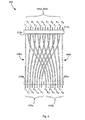
- Fig. 2 illustrates portions of an exemplary cable assembly 300 (See Fig. 3B and 4 ) for coupling the pins 120 of the processor 115 to the pins 110 of the probe 105.
- the cable assembly 300 includes a first group of wires 200a arranged side-by-side, and a second group of wires 200b arranged side-by-side.
- each wire may correspond to a coaxial wire that includes at least a center conductor and a shield.
- the coaxial wire may be a micro coaxial wire that has diameter of about 0.03556 cm (0.014 inches).
- a different wire, which has a different number of conductors and/or configuration, may be utilized.
- the wires of the first group of wires 200a may be spaced apart by a first distance 230 that may correspond roughly to the diameter of each wire so that adjacent wires touch one another.
- the wires may be spaced apart by about 0.04318 cm (0.017 inches).
- the wires may be spaced apart by a different distance.
- the wires may be spaced apart by a second distance 225 that is greater than the first distance 230.
- the second distance 225 between the wires at the second end 205 may correspond to roughly 2x the diameter of each wire, or about 0.07112 cm (0.028 inches).
- the spacing between the wires at the first end 210b and the second end 205b of the second group of wires 200b may be similarly configured.
- the second group of wires 200b are held in place relative to one another so that they are separated by a third distance 230b; and at a second end 205b, the wires are held in place relative to one another so that they are separated by a fourth distance 225b that is greater than the third distance 230b.
- a ribbonizing material 220a, 220b may be applied near respective first ends 210a, 210b of the first and second groups of wires 200a, 200b to hold the wires at the first ends 210a, 210b together.
- a ribbonizing material 215a, 215b may also be applied near respective second ends 205a, 205b of the first and second groups of wires 200a, 200b to hold the wires at the second ends 205a, 205b together.
- the ribbonizing material 215a, 215b and 220a, 220b may correspond to an adhesive-backed material, such as polyester film, that may have with a width of between about 2.54 cm (1 inch) and 7.62 cm (3 inches).
- the ribbonizing material may extend the length of the wires 200a, 200b.
- the ribbonizing material may be applied to the wires 200a, 200b during an extrusion process or other manufacturing processes for ribbonizing a group of wires.
- the ribbonizing material 215a at the second end 205a of the first group of wires 200a may be disposed along a bottom or first side of the group of wires 200a, and the ribbonizing material 215b at the second end 205b of the second group of wires 200b may be disposed along a top or opposite second side of the group of wires 200b, as illustrated in Fig. 2 .
- the opposite arrangement is also possible.
- the ribbonizing material 220a, 220b at the respective first ends 210a, 210b of the first and second groups of wires 200a, 200b may be disposed on either side of the respective groups of wires 200a, 200b.
- the first and second groups of wires 200a, 200b are arranged in the manner described above.
- the second group of wires 200b may be brought over the first group of wires 200a.
- the second group of wires 200b is lowered on to the first group of wires 200a so the ends of the wires are substantially aligned with one another, as illustrated in Fig. 3B , to provide the assembled cable 300.
- the ribbonizing material 215a, 215b secures the second ends 205a, 205b of the first and second groups of wires 200a, 200b in this configuration.
- an adhesive on the ribbonizing material 215a, 215b may secure the second ends 205a, 205b in this configuration.
- the cable assembly 300 overcomes the problems described above by converting a consecutive signaling arrangement to an odd/even or interleaved signaling arrangement.
- the first end 210a of the first group of wires 200a may be coupled to the transmit pins of the ultrasound processor 115 described above, and the first end 210b of the second group of wires 200b may be coupled to the receive pins.
- the interleaved second ends 205a, 205b of the first and second groups of wires 200a, 200b may be coupled to the interleaved transmit and receive pins of the ultrasound probe 105. This arrangement advantageously does away with the step of peeling apart wires, which is required in known cables.
Landscapes
- Health & Medical Sciences (AREA)
- Life Sciences & Earth Sciences (AREA)
- Engineering & Computer Science (AREA)
- Physics & Mathematics (AREA)
- Heart & Thoracic Surgery (AREA)
- Surgery (AREA)
- Nuclear Medicine, Radiotherapy & Molecular Imaging (AREA)
- Pathology (AREA)
- Radiology & Medical Imaging (AREA)
- Biomedical Technology (AREA)
- Veterinary Medicine (AREA)
- Medical Informatics (AREA)
- Molecular Biology (AREA)
- Biophysics (AREA)
- Animal Behavior & Ethology (AREA)
- General Health & Medical Sciences (AREA)
- Public Health (AREA)
- Computer Networks & Wireless Communication (AREA)
- Gynecology & Obstetrics (AREA)
- Manufacturing & Machinery (AREA)
- Ultra Sonic Daignosis Equipment (AREA)
- Computer Vision & Pattern Recognition (AREA)
- General Physics & Mathematics (AREA)
Abstract
Description
- The present invention relates generally to a cabling arrangement for an ultrasound system. More specifically, the present invention relates to ribbon cable that facilitates coupling an ultrasound processor with a consecutive signaling arrangement to a probe that has an interleaved signaling arrangement.
- Many medical devices include a base unit and a remote unit where the remote unit communicates information to and from the base unit. The base unit then processes information communicated from the remote unit and provides diagnostic information, reports, and the like. In some arrangements, a cable that includes a group of electrical wires couples the remote unit to the base unit. For example, signals may be communicated between an ultrasound probe and an ultrasound processor over a cable that includes hundreds of wires.
- The wires within the cable may be provided in the form of a ribbon cable where conductors are arranged next to one another, side-by-side, and held together by a ribbonizing material, such as plastic. For ultrasound systems, the respective ends of the ribbon cable are connected to the ultrasound probe and the ultrasound processor. Connection of the probe and processor is relatively easy when the pin out arrangements on the probe and processor match.
- When operating an ultrasound system in CW Doppler mode, the pins on the probe and processor may be configured so that half the pins are used for sending information to the transducers of the probe and the other half of the pins are used for receiving information from the transducers within the probe. In some ultrasound systems, this is accomplished by arranged the pins on the processor and probe so that a first group of adjacent pins is used to transmit transducer signals and a second group of adjacent pins is used to receive transducer signals. For example, pins 1-8 on both the probe and the processor may be used for sending transducer information, and pins 9-16 may be used for receiving transducer information.
- However, in other systems, the pin out arrangement of the probe and the processor do not match. For example, instead of having the grouped arrangement described above, the pin out on the probe may be configured so that the function (i.e., receiving and sending) alternates between odd and even-numbered pins. For example, pins one and three on the probe may be used for sending signals to transducers numbered one and two of the probe. Pins two and four may be used for receiving signals from the transducers numbered one and two, and so on. When the pin outs on the probe and processor do not match, an operator typically has to peel individual wires out of the ribbon at one end or the other and re-arrange the wires so that the signals are communicated correctly.
- In one aspect, a cable assembly includes a first group of wires arranged side-by-side. At a first end, the wires are held in place relative to one another so that the wires are separated by a first distance; and at a second end, the wires are held in place relative to one another so that the wires are separated by a second distance that is greater than the first distance. The cable includes a second group of wires arranged side-by-side. At a first end, the second group of wires are held in place relative to one another so that they are separated by a third distance; and at a second end, the wires are held in place relative to one another so that they are separated by a fourth distance that is greater than the third distance. The first group of wires is overlaid or overlays on the second group of wires such that the first end of the first group of wires is adjacent to the first end of the second group of wires, and each wire of the second end of the first group of wires is interleaved with a wire of the second end of the second group of wires.
- In a second aspect, a method for manufacturing a cable includes arranging a first group of wires side-by-side so that at a first end, the wires are separated by a first distance; and at a second end, the wires are separated by a second distance that is greater than the first distance. A ribbonizing material is applied over the first end and the second end of the first group of wires to hold the wires in place. The method also includes arranging a second group of wires side-by-side so that at a first end, the wires are separated by a third distance; and at a second end, the wires are separated by a fourth distance that is greater than the third distance. A ribbonizing material is applied over the first end and the second end of the second group of wires to hold the wires in place. The first group of wires is overlaid on the second group of wires such that the first end of the first group of wires is adjacent the first end of the second group of wires, and each wire of the second end of the first group of wires is interleaved with a wire of the second end of the second group of wires.
- In a third aspect, an ultrasound system includes an ultrasound probe, an ultrasound processor, and a cable assembly for communicating signals between the ultrasound probe and the ultrasound processor. The ultrasound probe has a first group of electrical contacts for sending transducer signals, and a second group of electrical contacts interleaved with the first group of electrical contacts for receiving transducer signals. The ultrasound processor has a first group of electrical contacts for sending transducer signals, and a second group of electrical contacts adjacent to the first group of electrical contacts for receiving transducer signals. The cable includes a first group of wires arranged side-by-side. At a first end, the wires are held in place relative to one another so that the wires are separated by a first distance; and at a second end, the wires are held in place relative to one another so that the wires are separated by a second distance that is greater than the first distance. The cable includes a second group of wires arranged side-by-side. At a first end, the second group of wires are held in place relative to one another so that they are separated by a third distance; and at a second end, the wires are held in place relative to one another so that they are separated by a fourth distance that is greater than the third distance. The first group of wires is overlaid on the second group of wires such that the first end of the first group of wires is adjacent to the first end of the second group of wires, and each wire of the second end of the first group of wires is interleaved with a wire of the second end of the second group of wires. The first ends of the first group of wires preferably lie on a line which constitutes an extension of a line on which the first ends of the second group of wires lie.
-
-
Fig. 1 illustrates an ultrasound system that includes a probe with an interleaved signaling arrangement and a processor with a consecutive signaling arrangement. -
Fig. 2 illustrates first and second groups of wires. -
Figs. 3A and 3B illustrate assembly of the first and second groups of wires into a cable assembly. -
Fig. 4 illustrates a top view of the cable assembly. - A cable assembly that overcomes the problems above is disclosed in detail below. Generally, the cable assembly includes a first group of wires and a second group of wires. At first ends of the respective groups of wires, the wires are spaced apart by a first distance. At second ends of the respective groups of wires, the wires are spaced apart by a second distance that is about double the first distance. The second group of wires is overlaid on top of the second group of wires so that, at the second ends, the respective wires of the groups are interleaved, while at the first end, the respective wires of the groups are arranged in a consecutive arrangement.
-
Fig. 1 illustrates anexemplary ultrasound system 100 that may include anultrasound processor 115 and aprobe 105. Theprobe 105 may include a number of transducers (not shown) configured to transmit an ultrasonic wave and to receive a corresponding echo of the ultrasonic wave. Theprobe 105 also includes a group ofpins 110 arranged in an odd/even or interleaved relationship, where odd-numbered pins are used to transmit signals to respective transducers, and even-numbered pins are used to receive signals from respective transducers. Each transducer is operatively coupled to a pair ofpins 110 on the probe. For example, a first transducer is coupled to pins T1 and R1, a second transducer is coupled to pins T2 and R2, and so on. While only a few pins are illustrated, it should be understood that, in practice, the number of pins might be much larger. - The
processor 115 may correspond to any system capable of communicating transducer signals to and from aprobe 105 for generating images associated with transducer signals. Theprocessor 115 includes a group ofpins 120 configured to send and receive information to correspondingpins 110 of the probe. As illustrated, thepins 120 may be arranged so that all the pins for transmitting transducer signals are grouped together on one side, and all the pins for receiving transducer signals from the probe are grouped together on the other side. In operation,pins 120 on theprocessor 115 are wired or coupled to like-namedpins 110 on the probe. For example, pin T1 on theprocessor 115 is wired or coupled to pin T1 on theprobe 105. The number of pins shown is only exemplary and, in practice, might be much larger. -
Fig. 2 illustrates portions of an exemplary cable assembly 300 (SeeFig. 3B and4 ) for coupling thepins 120 of theprocessor 115 to thepins 110 of theprobe 105. Thecable assembly 300 includes a first group ofwires 200a arranged side-by-side, and a second group ofwires 200b arranged side-by-side. In an exemplary implementation, each wire may correspond to a coaxial wire that includes at least a center conductor and a shield. For example, the coaxial wire may be a micro coaxial wire that has diameter of about 0.03556 cm (0.014 inches). A different wire, which has a different number of conductors and/or configuration, may be utilized. - At the
first end 210a, the wires of the first group ofwires 200a may be spaced apart by a first distance 230 that may correspond roughly to the diameter of each wire so that adjacent wires touch one another. For example, the wires may be spaced apart by about 0.04318 cm (0.017 inches). The wires may be spaced apart by a different distance. At thesecond end 205a, the wires may be spaced apart by asecond distance 225 that is greater than the first distance 230. For example, thesecond distance 225 between the wires at the second end 205 may correspond to roughly 2x the diameter of each wire, or about 0.07112 cm (0.028 inches). The spacing between the wires at thefirst end 210b and thesecond end 205b of the second group ofwires 200b may be similarly configured. At afirst end 210b, the second group ofwires 200b are held in place relative to one another so that they are separated by athird distance 230b; and at asecond end 205b, the wires are held in place relative to one another so that they are separated by afourth distance 225b that is greater than thethird distance 230b. - In some implementations, a
ribbonizing material first ends wires ribbonizing material second ends wires ribbonizing material wires wires - The
ribbonizing material 215a at thesecond end 205a of the first group ofwires 200a may be disposed along a bottom or first side of the group ofwires 200a, and theribbonizing material 215b at thesecond end 205b of the second group ofwires 200b may be disposed along a top or opposite second side of the group ofwires 200b, as illustrated inFig. 2 . The opposite arrangement is also possible. Theribbonizing material first ends wires wires - In operation, the first and second groups of
wires Fig. 3A , the second group ofwires 200b may be brought over the first group ofwires 200a. Next the second group ofwires 200b is lowered on to the first group ofwires 200a so the ends of the wires are substantially aligned with one another, as illustrated inFig. 3B , to provide the assembledcable 300. In some implementations, theribbonizing material wires ribbonizing material - As can be seen in
Fig. 4 , thecable assembly 300 overcomes the problems described above by converting a consecutive signaling arrangement to an odd/even or interleaved signaling arrangement. For example, thefirst end 210a of the first group ofwires 200a may be coupled to the transmit pins of theultrasound processor 115 described above, and thefirst end 210b of the second group ofwires 200b may be coupled to the receive pins. The interleaved second ends 205a, 205b of the first and second groups ofwires ultrasound probe 105. This arrangement advantageously does away with the step of peeling apart wires, which is required in known cables. - While the
cable assembly 300 has been described with reference to certain embodiments, it will be understood by those skilled in the art that various changes may be made and equivalents may be substituted without departing from the scope of the claims of the application. Various modifications may be made to adapt a particular situation or material to the teachings disclosed above without departing from the scope of the claims. Therefore, the claims should not be construed as being limited to any one of the particular embodiments disclosed, but to any embodiments that fall within the scope of the claims.
Claims (14)
- A cable assembly (300) comprising:a first plurality of wires (200a) arranged side-by-side, wherein at a first end (210a), the wires are held in place relative to one another so that at the first end (210a), the wires are separated by a first distance (230), and at a second end (205a), the wires are held in place relative to one another so that at the second end (205a), the wires are separated by a second distance (225) that is greater than the first distance (230);a second plurality of wires (200b) arranged side-by-side, wherein at a first end (210b), the second plurality of wires (200b) are held in place relative to one another so that at the first end (210b), the wires are separated by a third distance (230b), and at a second end (205b), the second plurality of wires (200b) are held in place relative to one another so that at the second end (205b), the wires are separated by a fourth distance (225b) that is greater than the third distance (230b),wherein the first plurality of wires (200a) is overlaid on the second plurality of wires (200b) such that the first end (210a) of the first plurality of wires (200a) is adjacent to the first end (210b) of the second plurality of wires (200b), and each wire of the second end (205a) of the first plurality of wires (200a) is interleaved with a wire of the second end (205b) of the second plurality of wires (200b).
- The cable assembly (300) according to claim 1, wherein the second distance (225) between the wires of the second end (205a) of the first plurality of wires (200a) is greater than or equal to the diameter of a wire of the second plurality of wires (200b).
- The cable assembly (300) according to any preceding claim, wherein the first plurality of wires (200a) are held in place at the second end (205a) via a ribbonizing material (215a) that runs along a bottom side of the first plurality of wires (200a), and the second plurality of wires (200b) are held in place at the second end (205b) via a ribbonizing material (215b) that runs along a top side of the second plurality of wires (200b).
- The cable assembly (300) according to claim 3, wherein the first plurality of wires (200a) are held in place at the first end (210a) via a ribbonizing material (220a) that runs along either a top or a bottom side of the first plurality of wires (200a), and the second plurality of wires (200b) are held in place at the first end (210b) via a ribbonizing material (220b) that runs along either a top or a bottom side of the first plurality of wires (200a).
- The cable assembly (300) according to claim 3 or 4, wherein the ribbonizing material (215, 215b, 220a, 220b) corresponds to an adhesive-backed material.
- The cable assembly (300) according to any preceding claim, wherein the first end (210a) of the first plurality of wires (200a) is configured to be coupled to a first group of electrical contacts (120, T1 ... T6) for sending transducer signals of an ultrasound processor (115), and the first end (210b) of the second plurality of wires (200b) is configured to be coupled to a second group of electrical contacts (120, R1...R6) for receiving transducer signals of the ultrasound processor (115).
- The cable assembly (300) according to claim 6, wherein the second end (205a) of the first plurality of wires (200a) is configured to be coupled to a first group of electrical contacts (110, T1...T8) for receiving transducer signals of the ultrasound probe (105), and the second end (205b) of the second plurality of wires (200b) is configured to be coupled to a second group of electrical contacts (110, R1...R8) for sending transducer signals of the ultrasound probe (105).
- The cable assembly (300) according to any preceding claim, wherein each wire of the first and second plurality of wires (210a, 210b) corresponds to a coaxial wire that includes at least a center conductor and a shield.
- A method for manufacturing a cable assembly (300) comprising:arranging a first plurality of wires (200a) side-by-side so that at a first end (210a), the wires are separated by a first distance (230), and at a second end (205a), the wires are separated by a second distance (225) that is greater than the first distance (230);applying a ribbonizing material (220a, 215a) over the first end (210a) and the second end (205a) of the first plurality of wires (200a) to hold the wires in place;arranging a second plurality of wires (200b) side-by-side so that at a first end (210b), the wires are separated by a third distance (230b), and at a second end (205b), the wires are separated by a fourth distance (225b) that is greater than the third distance (230b);applying a ribbonizing material (220b, 215b) over the first end (210b) and the second end (205b) of the second plurality of wires (200b) to hold the wires in place;overlaying the first plurality of wires (200a) on the second plurality of wires (200b) such that the first end (210a) of the first plurality of wires (200a) is adjacent to the first end (210b) of the second plurality of wires (200b), and each wire of the second end (205a) of the first plurality of wires (200a) is interleaved with a wire of the second end (205b) of the second plurality of wires (200b).
- The method according to claim 9, wherein the ribbonizing material (215a) that holds the first plurality of wires (200a) in place at the second end (205a) runs along a bottom side of the first plurality of wires (200a), and the ribbonizing material (215b) that holds the second plurality of wires (200b) in place at the second end (205b) runs along a top of the first plurality of wires (200a).
- The method according to claim 10, wherein the ribbonizing material (220a) that holds the first plurality of wires (200a) in place at the first end (210a) runs along either a top or a bottom side of the first plurality of wires (200a), and the ribbonizing material (220b) that holds the second plurality of wires (200b) in place at the first end (210b) runs along either a top or a bottom side of the second plurality of wires (200b).
- The method according to claim 9, 10 or 11, further comprising coupling the first end (210a) of the first plurality of wires (200a) to a first group of electrical contacts (120, T1...T6) for sending transducer signals of the ultrasound processor (115), and the first end (210b) of the second plurality of wires (200b) to a second group of electrical contacts (120, R1...R6) for receiving transducer signals of the ultrasound processor (115),
- The method according to claim 12, further comprising coupling the second end (205a) of the first plurality of wires (200a) to a first group of electrical contacts (110, T1...T8) for receiving transducer signals of the ultrasound probe (105), and coupling the second end (205b) of the second plurality of wires (200b) to a second group of electrical contacts (110, R1...R8) for sending transducer signals of the ultrasound probe (105).
- An ultrasound system (100) comprising:an ultrasound probe (105) having a first group of electrical contacts (110, T1...T8) for sending transducer signals, and a second group of electrical contacts (110, R1...R8) interleaved with the first group of electrical contacts (110, T1...T8) for receiving transducer signals;an ultrasound processor (115) having a first group of electrical contacts (120, T1...T6) for sending transducer signals, and a second group of electrical contacts (120, R1...R6) adjacent to the first group of electrical contacts (120, T1...T6), for receiving transducer signals; anda cable assembly (300) according to any one of claims 1 to 8 for communicating signals between the ultrasound probe (105) and the ultrasound processor (115).
Applications Claiming Priority (1)
| Application Number | Priority Date | Filing Date | Title |
|---|---|---|---|
| US14/482,560 US20160066892A1 (en) | 2014-09-10 | 2014-09-10 | Cable Assembly for Converting a Consecutive Signaling Arrangement to an Interleaved Signaling Arrangement |
Publications (1)
| Publication Number | Publication Date |
|---|---|
| EP2995256A1 true EP2995256A1 (en) | 2016-03-16 |
Family
ID=54150241
Family Applications (1)
| Application Number | Title | Priority Date | Filing Date |
|---|---|---|---|
| EP15183938.8A Withdrawn EP2995256A1 (en) | 2014-09-10 | 2015-09-04 | Cable assembly for converting a consecutive signaling arrangement to an interleaved signaling arrangement |
Country Status (5)
| Country | Link |
|---|---|
| US (1) | US20160066892A1 (en) |
| EP (1) | EP2995256A1 (en) |
| JP (1) | JP2016055163A (en) |
| KR (1) | KR20160030449A (en) |
| CN (1) | CN105395213A (en) |
Citations (4)
| Publication number | Priority date | Publication date | Assignee | Title |
|---|---|---|---|---|
| US5322974A (en) * | 1992-08-31 | 1994-06-21 | International Business Machines Corporation | Interleaved fine line cables |
| US20020139562A1 (en) * | 2001-03-30 | 2002-10-03 | Larry Daane | Flexible interconnect cable with ribbonized ends |
| US6498882B1 (en) * | 2000-11-28 | 2002-12-24 | Lightwave Microsystems Corporation | Assembly and method for reorganizing planar lightwave circuit channels |
| US6559389B1 (en) * | 2000-08-25 | 2003-05-06 | General Electric Company | High-density cable and method therefor |
Family Cites Families (3)
| Publication number | Priority date | Publication date | Assignee | Title |
|---|---|---|---|---|
| DE19931189A1 (en) * | 1999-07-07 | 2001-01-25 | Meritor Automotive Gmbh | Process for the production of components with electrical conductor tracks arranged therein, and components manufactured according to them, in particular as door modules for motor vehicles |
| CN101784175B (en) * | 2009-01-18 | 2012-04-18 | 富士康(昆山)电脑接插件有限公司 | Cable connector assembly and wire leveling method thereof |
| US8825130B2 (en) * | 2011-12-30 | 2014-09-02 | St. Jude Medical, Atrial Fibrillation Division, Inc. | Electrode support structure assemblies |
-
2014
- 2014-09-10 US US14/482,560 patent/US20160066892A1/en not_active Abandoned
-
2015
- 2015-09-01 JP JP2015171787A patent/JP2016055163A/en active Pending
- 2015-09-04 EP EP15183938.8A patent/EP2995256A1/en not_active Withdrawn
- 2015-09-07 KR KR1020150126053A patent/KR20160030449A/en not_active Withdrawn
- 2015-09-08 CN CN201510567612.3A patent/CN105395213A/en active Pending
Patent Citations (4)
| Publication number | Priority date | Publication date | Assignee | Title |
|---|---|---|---|---|
| US5322974A (en) * | 1992-08-31 | 1994-06-21 | International Business Machines Corporation | Interleaved fine line cables |
| US6559389B1 (en) * | 2000-08-25 | 2003-05-06 | General Electric Company | High-density cable and method therefor |
| US6498882B1 (en) * | 2000-11-28 | 2002-12-24 | Lightwave Microsystems Corporation | Assembly and method for reorganizing planar lightwave circuit channels |
| US20020139562A1 (en) * | 2001-03-30 | 2002-10-03 | Larry Daane | Flexible interconnect cable with ribbonized ends |
Also Published As
| Publication number | Publication date |
|---|---|
| US20160066892A1 (en) | 2016-03-10 |
| CN105395213A (en) | 2016-03-16 |
| KR20160030449A (en) | 2016-03-18 |
| JP2016055163A (en) | 2016-04-21 |
Similar Documents
| Publication | Publication Date | Title |
|---|---|---|
| US9184370B2 (en) | Ultrasonic transducer device, ultrasonic measurement apparatus, head unit, probe, and ultrasonic imaging apparatus | |
| US20160030003A1 (en) | Ultrasonic diagnostic device and method for supporting synchronous scanning with multiple probes | |
| JP5978649B2 (en) | Ultrasonic transducer element chip, probe head and probe, electronic device and ultrasonic diagnostic apparatus | |
| JP2011005233A (en) | Transducer for ultrasonic diagnosis device and method for manufacturing the same | |
| EP2474835A3 (en) | Diagnosis system, medical image system, and method of displaying diagnosis image | |
| US20160007962A1 (en) | Conductor interface for minimally invasive medical sensor assembly and associated devices, systems, and methods | |
| EP4609800A3 (en) | Ultrasonic diagnostic device and method for controlling ultrasonic diagnostic device | |
| CN103767732A (en) | Ultrasonic measurement device, head unit, probe, and diagnostic device | |
| JP5247960B2 (en) | High density cable and its manufacturing method | |
| EP2772315A3 (en) | Ultrasonic transducer device, head unit, probe, and ultrasonic imaging apparatus | |
| US20160066892A1 (en) | Cable Assembly for Converting a Consecutive Signaling Arrangement to an Interleaved Signaling Arrangement | |
| WO2014134318A3 (en) | Imaging devices with an array of transducers | |
| US7395189B2 (en) | Method and apparatus for switching among elements of a structural health monitoring system | |
| EP2772316A3 (en) | Ultrasonic transducer device, head unit, probe, and ultrasonic imaging apparatus | |
| US8657620B2 (en) | Connector assembly having a cable clamp coupled to a collet including an arbor | |
| CN108742701B (en) | Expansion module and expansion module for ultrasonic system | |
| JP5491717B2 (en) | Ultrasonic transducer, ultrasonic probe, and method of manufacturing ultrasonic transducer | |
| CN111433834A (en) | Flexible display screen and flexible equipment | |
| JP6334937B2 (en) | Ultrasonic diagnostic equipment | |
| WO2018230261A1 (en) | Convex-type ultrasound probe | |
| EP4344653A1 (en) | Ultrasound endoscopy | |
| JP4855317B2 (en) | Ultrasonic diagnostic apparatus and ultrasonic transducer connection relation determination method | |
| US11009561B2 (en) | Cable identification tester | |
| JP2005211096A (en) | Electronic scanning type ultrasonic inspection apparatus | |
| CN109499827B (en) | Ultrasonic transducer and method of manufacturing the same |
Legal Events
| Date | Code | Title | Description |
|---|---|---|---|
| PUAI | Public reference made under article 153(3) epc to a published international application that has entered the european phase |
Free format text: ORIGINAL CODE: 0009012 |
|
| AK | Designated contracting states |
Kind code of ref document: A1 Designated state(s): AL AT BE BG CH CY CZ DE DK EE ES FI FR GB GR HR HU IE IS IT LI LT LU LV MC MK MT NL NO PL PT RO RS SE SI SK SM TR |
|
| AX | Request for extension of the european patent |
Extension state: BA ME |
|
| 17P | Request for examination filed |
Effective date: 20160912 |
|
| RBV | Designated contracting states (corrected) |
Designated state(s): AL AT BE BG CH CY CZ DE DK EE ES FI FR GB GR HR HU IE IS IT LI LT LU LV MC MK MT NL NO PL PT RO RS SE SI SK SM TR |
|
| RAP1 | Party data changed (applicant data changed or rights of an application transferred) |
Owner name: TE CONNECTIVITY CORPORATION |
|
| STAA | Information on the status of an ep patent application or granted ep patent |
Free format text: STATUS: THE APPLICATION HAS BEEN WITHDRAWN |
|
| 18W | Application withdrawn |
Effective date: 20180809 |