EP2995226B1 - Barrière de protection pour un ensemble fermeture à glissière - Google Patents
Barrière de protection pour un ensemble fermeture à glissière Download PDFInfo
- Publication number
- EP2995226B1 EP2995226B1 EP15188735.3A EP15188735A EP2995226B1 EP 2995226 B1 EP2995226 B1 EP 2995226B1 EP 15188735 A EP15188735 A EP 15188735A EP 2995226 B1 EP2995226 B1 EP 2995226B1
- Authority
- EP
- European Patent Office
- Prior art keywords
- zipper
- barrier
- slider
- cover
- assembly
- Prior art date
- Legal status (The legal status is an assumption and is not a legal conclusion. Google has not performed a legal analysis and makes no representation as to the accuracy of the status listed.)
- Active
Links
- 230000004888 barrier function Effects 0.000 title claims description 198
- 230000001681 protective effect Effects 0.000 title claims description 26
- 239000002245 particle Substances 0.000 claims description 54
- 230000005012 migration Effects 0.000 claims description 30
- 238000013508 migration Methods 0.000 claims description 30
- 239000006260 foam Substances 0.000 claims description 10
- 239000000463 material Substances 0.000 description 29
- 206010004194 Bed bug infestation Diseases 0.000 description 12
- 241001414835 Cimicidae Species 0.000 description 12
- 239000004744 fabric Substances 0.000 description 9
- 230000000007 visual effect Effects 0.000 description 9
- 239000000428 dust Substances 0.000 description 7
- 241000238876 Acari Species 0.000 description 6
- 230000000712 assembly Effects 0.000 description 6
- 238000000429 assembly Methods 0.000 description 6
- 229920000642 polymer Polymers 0.000 description 6
- 230000008595 infiltration Effects 0.000 description 5
- 238000001764 infiltration Methods 0.000 description 5
- 239000000853 adhesive Substances 0.000 description 4
- 230000001070 adhesive effect Effects 0.000 description 4
- 239000013566 allergen Substances 0.000 description 4
- 230000000295 complement effect Effects 0.000 description 4
- 230000000284 resting effect Effects 0.000 description 3
- 241001327638 Cimex lectularius Species 0.000 description 2
- 241000258937 Hemiptera Species 0.000 description 2
- 230000008878 coupling Effects 0.000 description 2
- 238000010168 coupling process Methods 0.000 description 2
- 238000005859 coupling reaction Methods 0.000 description 2
- 230000002401 inhibitory effect Effects 0.000 description 2
- 238000005304 joining Methods 0.000 description 2
- 238000000034 method Methods 0.000 description 2
- 239000004593 Epoxy Substances 0.000 description 1
- 241000238631 Hexapoda Species 0.000 description 1
- 241001414987 Strepsiptera Species 0.000 description 1
- 230000009286 beneficial effect Effects 0.000 description 1
- 230000015572 biosynthetic process Effects 0.000 description 1
- 239000008280 blood Substances 0.000 description 1
- 210000004369 blood Anatomy 0.000 description 1
- 230000001419 dependent effect Effects 0.000 description 1
- 238000001035 drying Methods 0.000 description 1
- 230000006870 function Effects 0.000 description 1
- 239000003292 glue Substances 0.000 description 1
- 238000004900 laundering Methods 0.000 description 1
- 230000000670 limiting effect Effects 0.000 description 1
- 238000004519 manufacturing process Methods 0.000 description 1
- 238000003825 pressing Methods 0.000 description 1
- 230000002265 prevention Effects 0.000 description 1
- 239000011347 resin Substances 0.000 description 1
- 229920005989 resin Polymers 0.000 description 1
- 230000035807 sensation Effects 0.000 description 1
- 238000009958 sewing Methods 0.000 description 1
- 230000009182 swimming Effects 0.000 description 1
- 239000011800 void material Substances 0.000 description 1
- 238000005406 washing Methods 0.000 description 1
Images


Classifications
-
- A—HUMAN NECESSITIES
- A47—FURNITURE; DOMESTIC ARTICLES OR APPLIANCES; COFFEE MILLS; SPICE MILLS; SUCTION CLEANERS IN GENERAL
- A47C—CHAIRS; SOFAS; BEDS
- A47C31/00—Details or accessories for chairs, beds, or the like, not provided for in other groups of this subclass, e.g. upholstery fasteners, mattress protectors, stretching devices for mattress nets
- A47C31/007—Anti-mite, anti-allergen or anti-bacterial means
-
- A—HUMAN NECESSITIES
- A47—FURNITURE; DOMESTIC ARTICLES OR APPLIANCES; COFFEE MILLS; SPICE MILLS; SUCTION CLEANERS IN GENERAL
- A47C—CHAIRS; SOFAS; BEDS
- A47C31/00—Details or accessories for chairs, beds, or the like, not provided for in other groups of this subclass, e.g. upholstery fasteners, mattress protectors, stretching devices for mattress nets
- A47C31/10—Loose or removable furniture covers
- A47C31/105—Loose or removable furniture covers for mattresses
-
- A—HUMAN NECESSITIES
- A47—FURNITURE; DOMESTIC ARTICLES OR APPLIANCES; COFFEE MILLS; SPICE MILLS; SUCTION CLEANERS IN GENERAL
- A47G—HOUSEHOLD OR TABLE EQUIPMENT
- A47G9/00—Bed-covers; Counterpanes; Travelling rugs; Sleeping rugs; Sleeping bags; Pillows
- A47G9/02—Bed linen; Blankets; Counterpanes
- A47G9/0238—Bed linen
- A47G9/0253—Pillow slips
-
- A—HUMAN NECESSITIES
- A47—FURNITURE; DOMESTIC ARTICLES OR APPLIANCES; COFFEE MILLS; SPICE MILLS; SUCTION CLEANERS IN GENERAL
- A47G—HOUSEHOLD OR TABLE EQUIPMENT
- A47G9/00—Bed-covers; Counterpanes; Travelling rugs; Sleeping rugs; Sleeping bags; Pillows
- A47G2009/001—Anti-allergen; Anti-mite
-
- Y—GENERAL TAGGING OF NEW TECHNOLOGICAL DEVELOPMENTS; GENERAL TAGGING OF CROSS-SECTIONAL TECHNOLOGIES SPANNING OVER SEVERAL SECTIONS OF THE IPC; TECHNICAL SUBJECTS COVERED BY FORMER USPC CROSS-REFERENCE ART COLLECTIONS [XRACs] AND DIGESTS
- Y10—TECHNICAL SUBJECTS COVERED BY FORMER USPC
- Y10T—TECHNICAL SUBJECTS COVERED BY FORMER US CLASSIFICATION
- Y10T24/00—Buckles, buttons, clasps, etc.
- Y10T24/25—Zipper or required component thereof
- Y10T24/2514—Zipper or required component thereof with distinct member for sealing surfaces
Definitions
- the present disclosure relates to a barrier for a zipper assembly.
- the barrier is used with a zipper assembly to prevent the infiltration of small particles and/or organisms from one side of a barrier to an opposite side of the barrier.
- Bed bugs are a type of small parasitic insect that prefers to feed on human blood and that can dwell within bed mattresses.
- a fabric cover or encasement may be provided to surround the mattress so as to prevent the bugs from escaping.
- the encasement is typically placed around the mattress and closed by a zipper so that the bed bugs encounter the barrier of the fabric cover and are unable to exit.
- FIG. 1A depicts a conventional zipper assembly 10 having two strips of fabric tape 40 each affixed to corresponding zipper tracks 32, 34.
- the zipper tracks each have a number of teeth 36 that can be enmeshed together to form a set of linked zipper tracks 30.
- a zipper slider 20, having a Y-shaped channel, is manipulated by a user pulling a tab 22 to move the zipper slider along the rows of teeth so as to bring opposing rows of teeth together into a mesh, or to separate previously enmeshed teeth.
- the zipper can be opened or closed.
- the zipper may be pulled in a direction (e.g., upward) so as to reach a closed position and such that the linked zipper tracks 30 may largely restrict the passage of small particles or organisms from one side of the zipper to the other.
- a small space e.g., about 5 mm 2 in area
- small particles or organisms might move will almost inevitably exist at the top of the zipper.
- CN 201 839 825 U which forms the basis for the preamble of independent claim 1, relates to an insect prevention zipper coat with a magic tape arranged on two sides of a sewing part in the closing position of the zipper, and a hook surface of another magic tape that corresponds in position to that of the magic tape on the two sides of the zipper.
- the inventors have recognized that, when closing a zipper, no matter how tightly the zipper is pulled shut, a small hole will still remain between the zipper slider and the end of the zipper tracks. This hole will often provide a passageway through which small particles or organisms are able to infiltrate or escape from one side of the closed zipper to the other. Embodiments described herein relate to the appreciation that it would be beneficial to obstruct and/or block exit from such a passageway so as to limit the migration of small particles or organisms.
- Zipper assemblies include a zipper slider for manipulating a pair of zipper tracks between open and closed positions of the zipper assembly and may be used with the present barrier that is engageable with the zipper slider resulting in an obstruction that blocks migration of small particles and/or organisms through regions of the zipper assembly or from one side of the zipper or the barrier to another.
- the barrier includes a base having a base surface that is attachable to an article, for example, a padding or bedding material (e.g., mattress/pillow cover) or bag/luggage, that is opened and closed by the zipper.
- the barrier includes a slider connecting region comprising a recess constructed to receive an appropriate connection portion of a zipper slider (e.g., a front piece of the zipper slider, the zipper slider itself, etc.) upon closing of the zipper assembly.
- an obstruction is formed by the connection between the barrier and zipper slider, preventing the migration of small objects such as bed bugs, other organisms or particles from one surface of the barrier to an opposite surface of the barrier (e.g., between upper and lower regions of the barrier).
- Barriers described herein may be used for articles for bedding arrangements (e.g., mattress/pillow covers, duvets, comforters, sleeping bags, etc.) or other padding materials that are opened and closed by a zipper.
- bedding arrangements e.g., mattress/pillow covers, duvets, comforters, sleeping bags, etc.
- other padding materials that are opened and closed by a zipper.
- bed bugs may be prevented from migrating through the small opening that is commonly present in the zipper assembly between the zipper slider and the end of the zipper tracks.
- a barrier according to claim 1 is provided.
- the protective assembly includes a pair of zipper tracks including a first plurality of teeth engageable with a second plurality of teeth; a zipper slider constructed and arranged with the pair of zipper tracks to manipulate the pair of zipper tracks between an open position and a closed position, and a barrier according to the invention.
- aspects discussed herein relate to a protective barrier at the end of a pair of linked zipper tracks of a zipper assembly so as to obstruct the migration of small particles and/or organisms from one side of the barrier to the opposite side of the barrier when the zipper assembly is closed.
- traditional zippers incorporated on an article e.g., padding material, mattress/pillow covers, duvets, comforters, etc.
- a narrow opening at the end of the zipper tracks will almost invariably remain.
- Such an opening may be large enough (e.g., between about 1 and 10 mm 2 ) for small organisms such as bed bugs and/or dust mites to migrate or crawl through the passageway provided by the narrow opening and move freely from one side of the article to the other.
- embodiments of protective assemblies described herein may provide certain advantages by being constructed in a manner that creates an obstruction that blocks or minimizes openings which commonly remain at the end of a closed zipper and, thus, prevents or reduces the migration of particles and/or organisms between opposite sides at the end of the zipper. Therefore, when the zipper is closed, small particles or organisms can be substantially prevented from migrating freely from an interior region of the article to the exterior (or vice versa).
- a barrier in all embodiments, includes a base surface that may be attached to a suitable article (e.g., padding material such as fabric for use in a bedding or furniture arrangement).
- a particular region of the barrier is suitably adapted to form a connection with a portion of a zipper slider upon closing of the zipper assembly.
- Such a connection results in the formation of an obstruction, which can inhibit movement of small objects such as allergens, particles, dust mites, bed bugs and/or other organisms between opposing surfaces of the barrier (and, for example, the fabric) proximate to the zipper slider and at the end of the linked zipper tracks of the zipper assembly.
- the barrier is configured as a plug where a portion of the barrier has a structural feature that engages with a complementary structural portion of a zipper slider to form an obstruction by the resulting connection with the zipper slider.
- the barrier includes a cover that engages with at least a portion of a zipper slider to create a suitable obstruction.
- the zipper slider may form a flush connection with the base and the cover may enclose the zipper slider and a portion of the zipper tracks to establish one or more obstructions that prevent the migration of particles/organisms past a portion of the barrier (e.g., past a base portion of the barrier or between upper and lower regions of the barrier).
- placing the zipper assembly in a closed position may result in a suitable connection between an appropriate barrier and a zipper slider that is free of openings greater than a certain amount of surface area.
- such a connection between a barrier and a zipper slider may be free of openings that are greater than 20 mm 2 , greater than 10 mm 2 , greater than 5 mm 2 , or greater than 1 mm 2 in surface area.
- connection between the barrier and zipper slider may prevent the escape of particles or organisms from underneath the barrier (or base of the barrier) to above the barrier (or base of the barrier), or vice versa.
- the zipper slider may be pressed against a portion of the base so that the zipper assembly itself is closed, and the cover may be brought over the top of the zipper slider so as to form a press fit or snap fit with the base.
- Appropriate material e.g., foam, plastic, polymer, cushioning, padding
- Such an arrangement may form one or more suitable obstructions that prevent the migration of particles or organisms from one side of the barrier to the other.
- a suitable connection between the barrier and zipper slider may obstruct migration of particles/organisms between different regions (e.g., upper and lower regions) of the barrier where the particles/organisms are less than 5 mm, less than 1 mm, less than 100 microns, less than 50 microns, less than 10 microns, or less than 1 micron in size.
- FIG. 1B illustrates a mattress cover 400 that provides a protective encasement for a mattress " M .”
- the mattress cover 400 may include a zipper assembly 100 for use in separating or joining together different fabric portions of the cover.
- mattress covers may include protective assemblies having a zipper and a barrier disposed on a portion of the mattress cover that can engage with a corresponding zipper slider to provide an appropriate obstruction upon connection. Such a connection can provide a suitable obstruction that, for example, effectively blocks bed bugs, dust mites, allergens and/or other small particles from entering and exiting the mattress cover.
- Suitable articles described herein may be useful for any purpose where zippers are used, such as for mattress covers, encasements, pillow covers, linen sheets (e.g., duvets, comforters, etc.), padding materials, curtains, drapes, protective coverings (e.g., for swimming pools, tubs, etc.), outdoor equipment (e.g., tents, jackets, etc.) articles of clothing, luggage, carrying cases, suitcases, bags (e.g., gym bags, backpacks, etc.), or any other suitable application.
- Suitable materials for the articles may include, for example, fabric, plastic, polymer, or any other appropriate material.
- portions of padding/bedding material or another appropriate article may be attached to respective zipper tracks and may be suitably joined together or separated depending on whether the zipper slider is manipulated into an opening or closing direction.
- the barrier includes a base surface 512 that can be appropriately attached to the article via any suitable fastening arrangement.
- the barrier can be attached to the article at a suitable location on the article proximate the end of the zipper assembly so that the barrier may be in position to form an obstruction by the connection with the zipper slider when the zipper assembly is closed.
- the barrier is adhesively attached to the article.
- a suitable adhesive e.g., resin, epoxy, glue, etc.
- resin, epoxy, glue, etc. may be applied to the base surface of the barrier and/or an appropriate location on the article so as to affix the barrier to the article.
- the barrier is stitched or stapled to the article.
- the barrier may have holes (not shown in the figures) through which a suitable thread/yarn or staples may pass for attachment of the barrier to a suitable article (e.g., fabric).
- the barrier is attached to the article via a hook and loop fastener arrangement.
- the base surface of the barrier may include one surface of a hook and loop fastener arrangement (e.g., hooks) and an appropriate location on the article may include a complementary surface of the hook and loop fastener arrangement (e.g., loops).
- a zipper assembly and appropriate article is arranged to include a protective barrier attached to the article that may provide suitable blockage of small particles and/or organisms between interior and exterior surfaces of the article that extend beyond the barrier
- the zipper may be inadvertently left open.
- a situation may arise where a user pulls the tab 122 to close the zipper and even though the zipper slider is moved in close proximity to the barrier, a preferred connection or engagement between the zipper slider and the barrier is not made; that is, for some embodiments, the zipper slider is not adequately engaged with or "plugged" into the barrier and a proper obstruction between the zipper slider and the barrier preventing small particle/organism migration from one side of the barrier to an opposing side is absent.
- embodiments described herein may also include a notification system that produces a notification signal to a user upon proper connection of the zipper slider and the barrier.
- a notification member when the slider connecting region of the barrier and the barrier connection portion of the zipper slider are connected so as to form an appropriate obstruction that prevents migration of small particles and/or organisms, a notification member produces an appropriate signal (e.g., audible, visual, tactile, etc.) that informs the user that the zipper is adequately closed and that the zipper slider and barrier are suitably connected.
- the notification member may include a device that produces an audible and/or tactile signal for the user to be notified that the zipper assembly is fully closed and that small particle/organism escape from or infiltration of the article (e.g., bedding cover, bag/luggage, etc.) will not occur.
- a notification member may include a snap-fit or press-fit device situated at a suitable region of the barrier and/or the zipper slider. Accordingly, once the zipper is completely closed and the zipper slider is fully engaged with the barrier so as to form a suitable obstruction for small particles/organisms, an audible clicking sound can be heard by the user, informing the user that the zipper assembly is appropriately and sufficiently closed. Or, if the nature of the fit does not produce an audible sound, a user may be able to feel through a tactile sensation (e.g., through an interference fit) that suitable engagement between the zipper slider and the barrier has been established.
- a tactile sensation e.g., through an interference fit
- the notification member may include a visual indicator that visually informs the user that the zipper assembly is fully and suitably closed such that a suitable obstruction for small particles and organisms is formed.
- the notification member may include a line or color drawn on an upper surface of the barrier that, if visible, indicates to a user that the zipper has not yet been fully closed and, thus, a proper obstruction to bed bug infiltration has not been formed.
- a small button or lever equipped with a spring may be included in the sliding connecting region of the barrier that is connected to a visual indicator located on an upper surface of the barrier and/or the zipper slider.
- the visual indicator provides a visual display (e.g., red color, open symbol, etc.) showing that the zipper slider and barrier are not fully connected.
- the visual indicator shows a display (e.g., green color, closed symbol, etc.) notifying the user that the zipper slider and barrier are properly connected.
- the user closes the zipper assembly, he/she can check the notification member or simply be informed by the notification member to see whether the zipper assembly has been properly closed to prevent small particle/organism migration between upper and lower surfaces of the barrier and regions of the article extending from the barrier.
- a notification system that does not produce an audible or visual signal may be utilized.
- a protective barrier for a zipper includes a housing or cover constructed to cover and/or enclose at least a portion of the base and that may be attached to the base and/or the article by any suitable method (e.g., using a temporary or permanent fastening arrangement).
- the housing or cover may also be constructed to cover the front region of the zipper slider when the slider connecting region of the barrier and the barrier connection portion of the zipper slider are connected.
- the housing or cover may be constructed to cover the entire zipper slider when the zipper assembly is placed in a closed position. Such a housing or cover may provide added protection for the connection between the zipper slider and barrier, for example, so that it is less likely for the zipper slider to become dislodged from the barrier.
- the housing may also help to prevent the zipper assembly from becoming partially unzipped, for example, resulting from incidental movement or rustling of the zipper assembly and/or article.
- the housing or cover may further contribute to obstructing migration of particles or organisms between opposing sides of the barrier.
- a snap-fit arrangement may be provided where, upon connection of the zipper slider and the barrier, a snap-fit device works to hold the zipper slider and barrier connection in place.
- a lock-mechanism may be employed. For example, when the zipper slider and the barrier are suitably connected, the user may actuate an appropriate lock device that holds the plugged connection in place.
- the user When the zipper assembly is to be opened, the user would first unlock the device and then separate the zipper slider from the barrier, subsequently pulling apart the zipper tracks.
- the barrier connection portion of the zipper slider and the slider connecting region of the barrier may be appropriately shaped to form an interference fit with one another upon connection, providing resistance to the zipper slider and the barrier being disconnected.
- FIGS. 9-10C illustrate an embodiment of a barrier 500 that may be used with a zipper assembly and article (e.g., bedding/padding materials) for obstructing the migration of particles and/or organisms, such as allergens, bed bugs or dust mites, when the zipper assembly is placed in a closed position.
- the barrier may be placed into a coupled arrangement with a zipper slider so as to prevent the infiltration of small particles and/or organisms through regions of the zipper assembly and/or out from the barrier 500.
- an opening between the zipper slider and the end of the zipper tracks may still remain regardless of how tightly the zipper slider is drawn to the end of the zipper tracks.
- Barrier devices described herein inhibit or block such migration near the opening and/or inhibit migration out of the barrier.
- the barrier 500 includes a base 510 having a bottom surface having a flange that can be attached to any suitable surface, such as an article, for example, bedding materials (e.g., mattress/pillow cover), protective coverings, clothing, outdoor equipment, furniture, baggage, luggage, etc.
- bedding materials e.g., mattress/pillow cover
- the flange can be glued or stitched to the article or may be attached using any suitable arrangement or any combination of arrangements.
- the barrier includes a slider connecting region 540, illustrated as a recess or cutout/void in the base 510 within which the zipper slider may reside when the zipper assembly is placed in a closed position.
- the shape of the recess may complement the shape of the zipper slider so as to form a generally flush fit that blocks off potential paths through which particles and/or organisms may migrate.
- the slider connecting region 540 shown in FIG. 9 includes a slider padding 542 that is formable in a manner where the padding conforms to the front of zipper slider so that no gaps arise when the zipper is coupled to the barrier.
- the slider padding may include any suitable material, such as a foam (e.g., open or closed cell foam), polymer, cushion, or the like, and is not limited in this regard.
- the slider padding may include a soft deformable material (e.g., foam, sponge-like material, cushioning) covering over a more rigid plastic portion.
- the padding may not be used at all and the zipper instead presses up against or conforms generally to the rigid material of the base.
- the base includes a receiving region 520 formed as a cut-away recess shaped to accept a zipper tab.
- the receiving region 520 incorporates detents 522 that serve as holders to arrest movement of the zipper tab when an interference fit is formed between the zipper tab and the detents (as shown in FIG. 13 ); hence, the zipper slider is also firmly situated with respect to the barrier.
- the receiving region may also include a post 530 that may function as a holder for the zipper tab. In this respect, the post may accept an opening of the zipper tab, allowing for the zipper slider and tab to be further coupled with the barrier.
- Such arrangements may provide for the zipper to remain securely coupled with the barrier so as to maintain the zipper assembly in a closed position, creating a first obstruction of any zipper opening by maintaining the zipper slider in close abutting relationship with the shaped wall or slider padding 542, thereby inhibiting movement of particles and/or organisms past the obstruction.
- any suitable structure other than detent(s) or a post may be provided for securing the zipper tab within the receiving region.
- the receiving region may include a suitable adhesive so that the zipper tab adheres to portions of the receiving region upon contact with the adhesive.
- a hook (not shown) may be provided for suitably engaging and securing the zipper tab and/or slider within the receiving region. In some embodiments, such a hook may be actuated by a user for appropriately engaging and disengaging the barrier with the zipper tab and/or slider.
- a suitable adhesive or hook and loop fasteners may be used to secure the zipper slider or tab within the receiving region.
- the base 510 is connected to a cover 560 via a connection member 550 such as, in the example shown, an integrally formed hinge.
- the barrier 500 may be closed by a user manipulating the cover 560 along the direction depicted by the curved arrow shown in FIG. 9 , relative to the base 510.
- the barrier is closed when the surface 562 of the cover 560 is brought into contact with a surface 512 of the base 510.
- the barrier may be closed when the surface 572 comes into contact with the zipper tracks and/or article to which the barrier is affixed; and when the surface 574 contacts the surface 524 of the base.
- a user may grasp tab 564 to facilitate opening and closing of the barrier.
- the cover 560 includes an upper padding 570 having a first padding surface 572, a second padding surface 574 and a third padding surface 576.
- the cover 560 may be brought toward the base 510 of the barrier such that the upper padding 570 comes over the zipper slider resulting in the zipper slider and zipper tab being enclosed within the barrier.
- the foam pad 570 when the cover is in the closed position, presses against the zipper tracks, zipper slider and/or base surfaces and provides a second obstruction that blocks egress from the device 500 should migration through the zipper opening occur. It should be appreciated that the invention is not limited to employing both the first and second obstructions and that in some embodiments only the first obstruction is provided.
- the first padding surface 572 is lowered so as to come into contact with the zipper tracks behind the zipper slider (e.g., may be flush contact between the first padding surface 572 and the zipper tracks).
- second padding surface 574 comes into contact with upper surface 524 of base 510.
- third padding surface 576 comes into contact with side surfaces 526 of the base.
- any portion of the upper padding 570 may come into contact with any suitable region of the base; for instance, the padding may be deformable such that portions of the padding may be appropriately bunched together or stretched to suitably contact various regions of the barrier. Accordingly, closure of the barrier so as to bring upper padding 570 around and over the rear side of the zipper slider may further contribute to inhibiting migration of bed bugs from the device.
- the upper padding may include any appropriate material, without limitation, such as a foam (e.g., open or closed cell foam), polymer, cushion, or the like. Such material may be repeatedly washed and dried without damage in the ordinary course of use.
- the upper padding 570 may conform to the shape of the zipper slider and/or zipper tab providing a suitable obstruction that prevents particles and/or organisms from passing.
- the barrier 500 is made of any suitable material such as a polymer or other material that can be subject to washing/drying, repeated opening/closing of hinge, etc.
- the barrier may include any appropriate material that is generally durable and can withstand regular laundering and consumer use.
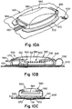
- FIGS. 10A-10C depict various views of the embodiment where the barrier is closed.
- the exterior surface of the cover 560 includes an overmold 580, such as rubber, plastic, polymer, or any other suitable material.
- the tab 564 and overmold 580 may provide further ease of use for a user in handling the barrier, as well as provide aesthetic qualities.
- the barrier 500 is disposed above the surface of article 400 (e.g., mattress cover, pillow surface, bag exterior, etc.) and may be attached in any suitable manner, as described above.
- the zipper barrier connection portion 140 of a zipper slider is shown in engagement with a complementary surface, such as of a slider padding 542. Zipper pull tab 122 is engaged on post 530.
- the cover is closed and foam pad 570 is behind the zipper pull pressing against the zipper tracks.
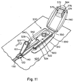
- FIGS. 11-14 illustrate operation of the embodiment shown in FIGS. 9-10C in conjunction with a zipper assembly.
- the barrier is suitably attached to the article 400 and the zipper tracks 130 to form a path through which the zipper slider 120 may slide into coupling arrangement with the barrier.
- the zipper slider 120 is depicted on approach toward the barrier 500 along the direction illustrated by the arrow in FIG. 11 .
- the zipper assembly is not quite in a closed position, as the zipper slider 120 is not yet placed in a suitably coupled arrangement with the barrier 500 so as to block small particles and/or organisms from migrating through the zipper opening (e.g., between a lower region and an upper region of the barrier).
- small objects and/or organisms such as bed bugs or dust mites would be able to move through an aperture between the end of the linked zipper tracks and the barrier from a lower region to an upper region of the barrier and back, from the interior to the exterior of the article (e.g., bedding/padding material) and back, or merely from underneath the base of the barrier to above the base of the barrier and back.
- a barrier connection portion 140 to be coupled with a slider connecting region may include a portion of a zipper slider or the zipper slider itself. Accordingly, the barrier connection portion 140 which, in the embodiment of FIG. 11 includes the entire zipper slider 120, is moved closer toward the slider connecting region 540 along the direction arrow shown. As described previously, a small opening in the zipper tracks may exist regardless of how much a user tries to close the zipper. However, engaging the zipper slider with the barrier brings the zipper assembly to a position where the small opening through which small particles/organisms would otherwise be able to travel is blocked.
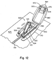
- the zipper slider 120 is positioned within the recess of the slider connecting region 540 such that the front end of the zipper slider is pushed up flush against the padding 542.
- the zipper assembly is placed in a closed position where migration of small particles and/or organisms is sufficiently obstructed from migrating and adequately obstructs ingress and egress of particles and organisms from traversing through this region.
- cover 560 comes down over the base 510 such that upper padding 570 suitably engages with surfaces of the base and the underlying zipper tracks where ingress and egress of particles and organisms from entering/exiting the barrier is inhibited.
- the zipper tab 122 is placed into the receiving region 520 of the barrier so as to additionally engage the zipper with the barrier. Accordingly, the zipper tab forms an interference fit with the detents 522, further securing the zipper assembly in the closed position.
- the detents, or any other suitable structure within the barrier may serve as a notification, such as by providing a notification signal (e.g., tactile and/or audio feedback) informing the user that the interference fit has occurred and that the zipper assembly is in the closed position. For example, pushing the tab into the receiving region may produce an audible clicking sound that may be heard by a user or a snap fit that can be felt by a user as an indication that the zipper tab is secured within the receiving region of the barrier.
- a notification signal e.g., tactile and/or audio feedback
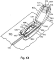
- FIG. 13 illustrates the zipper tab to be placed into engagement with the post 530 in a manner where the post enters through the opening 123, further securing the zipper slider and tab in place.
- the connection between the opening 123 and the post 530 maintains the zipper slider in place. Accordingly, when opening the zipper assembly, a user would have to pull the zipper tab up from the post 530 before attempting to open the zipper.
- the coupling between the opening 123 and post 530 may or may not include an interference fit arrangement.
- any suitable method or structure may be used to keep the zipper tab and slider situated with the barrier so that the zipper assembly remains secure so as to form an obstruction to the migration of particles and/or organisms between an interior and exterior of the article 400 past various portions of the barrier (e.g., past a base portion of the barrier, past surfaces 526 of the barrier, past the entire barrier structure itself, etc.).
- a space 528 within the receiving region may remain so that the zipper tab may be suitably disengaged from the receiving region.
- a user may place his or her finger tip in the space 528 to gain access to pull an edge of the tab with sufficient force to overcome the interference fit connection between the opening 123 and the post 530, if necessary, and bring the tab out of the receiving region. Similar to that shown in FIG. 12 , once the zipper tab is disengaged with the receiving region, the zipper slider could then be easily maneuvered back and forth with respect to the barrier between open and closed positions.
- FIG. 13 also depicts an arrow indicating the direction in which the cover 560 may be manipulated to close the barrier over and cover the zipper slider and zipper tab.
- a user manipulates the cover 560 relative to the base 510 (e.g., grasping the tab, pushing against the exterior surface of the cover, etc.) so that surfaces 512, 562 come into contact with one another.
- the cover 560 and base 510 are mutually attached via a snap fit configuration.
- the upper padding 570 may engage with the zipper tracks at the rear side of the zipper slider to provide a seal-like arrangement to further obstruct migration of small particles and/or organisms.
- FIG. 14 illustrates the barrier closed over and enclosing the zipper slider and zipper tab, further securing the zipper assembly in a closed configuration where particles and/or organisms are restricted or prevented from migrating from beneath the barrier, out of the barrier, and back.
- the upper padding 570 is disposed at the rear of the zipper slider and engages the zipper tracks to block migration of small particles and organisms.
- the first padding surface 572 resides against the closed zipper tracks located within the barrier, the second padding surface 574 comes into flush contact with upper surfaces 524, and the third padding surface 576 comes into flush contact with side surfaces 526. Accordingly, small particles and/or organisms are prevented from migrating between an interior and an exterior of the article (e.g., bedding/padding material) past surfaces of the barrier and/or zipper slider that are in contact with one another. In the embodiment, small particles and/or organisms are prevented from migrating past a base portion of the barrier. In the embodiment, small particles and/or organisms are prevented from migrating past surfaces between a base and a cover of the barrier that are in contact as well as surfaces between the zipper slider and the barrier that are in contact.
- the article e.g., bedding/padding material
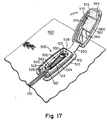
- FIGS. 15A-18B illustrate operation of another embodiment of a barrier 500.
- the barrier may be used with a zipper assembly and appropriate article (e.g., bedding/padding materials) for obstructing the migration of particles and/or organisms from one side of the barrier to an opposite side when the zipper assembly is placed in a closed position.
- the base 510 includes a slider connecting region 540, provided as a recess or cutout space within which the zipper slider may reside when the zipper assembly is placed in a closed position.
- a user may pull the zipper tab 123 toward the barrier along the direction indicated by the arrow shown in FIG. 15A .
- the slider padding 542 of the slider connection region 540 extends into the recess and may be deformable such that when the zipper slider pressed up against the padding, the padding conforms to the shape of the front portion of the zipper slider. When pressed against one another, a snug fit is formed between the slider and the padding so as to obstruct migration of small particles/organisms through the recess between the slider and the padding.
- the slider connecting region 540 includes detents 523 that may resist movement of the zipper slider by virtue of their protrusion into the slider as the slider moves relative to the detents, forward or backward through the connecting region 540. That is, for some embodiments, to move the zipper slider past the detents for closing the zipper assembly, a user may need to pull the zipper tab or push the zipper slider with slightly more force than would otherwise be necessary for moving the slider along other regions of the zipper tracks.
- FIG. 16 illustrates the zipper slider pressed up against the padding 542 where some extra effort may have been exerted for the slider to move past the detents 523.
- the zipper tab may be placed into engagement with the post 530 similarly to that shown and described for FIG. 13 .
- the zipper tab 122 may optionally be placed within the receiving region 520 and rest secured where the tab remains substantially parallel with respect to the base of the barrier.
- the upper padding 570 of the cover 560 extends outside the boundary defined by the surface 562. For instance, a portion of the padding 570 is adhered to the inner surface of the cover and another portion of the padding spills out past edges of the cover extending toward the tab 564.
- the cover 560 may be brought toward the base 510 in the direction indicated by the arrow shown in FIG. 17 so as to close the barrier.
- the cover 560 and the base 510 are suitably fastened to one another (e.g., interference fit, snap fit).
- FIGS. 18A-18B illustrate a closed barrier where the cover encloses the zipper slider and tab.
- the padding 570 substantially surrounds the rear of the zipper slider and presses against the zipper tracks.
- a first padding surface 572 that extends outside the cover and toward the cover tab 564 may be pressed down against the zipper tracks and a second padding surface 574 that remains within the space enclosed by the cover may be pressed down against the zipper slider and tab.
- the padding 570 creates an additional obstruction that blocks migration of small particles/organisms past the barrier 500.
- the zipper tab 122 when the barrier is closed, the zipper tab 122 is appropriately placed in a resting position within the receiving region 520 and enclosed by the cover. Accordingly, when placed in this resting position, the zipper tab 122 does not interfere with the obstruction formed by the padding 570 along the zipper tracks.
- an appropriate indication may be provided so as to notify an inspector that the barrier is properly installed in creating the suitable obstruction(s).
- Such an indication will allow a person to determine with confidence that small organisms or particles are prevented from migrating from the space enclosed by the article (e.g., bedding, padding, bag) to the exterior surface of the article and outside the barrier, or vice versa. If, for example, someone who is inspecting whether the zipper assembly and the barrier are both properly closed and installed is not able to receive notification of such an indication, then the zipper assembly and/or barrier would have to be further manipulated to so that the appropriate obstruction(s) are formed.
- the cover has a window 590 that is transparent or translucent, allowing for an inspector to view through the window 590 whether the zipper tab is appropriately placed.
- FIG. 18A illustrates a zipper and barrier that are properly closed where the tab 122 is visibly shown through the window 590.
- the window may be a separate element or the material itself that forms the device.
- the cover 560 may be comprised of a transparent or translucent material where the window and the cover are one in the same. That is, in this embodiment, the window is an integral part of the cover.
- the window is formed as a separate material apart from the cover and joined with other components to form the cover through a suitable manufacturing process.
- the zipper tab is optionally colored in a manner that provides a visual contrast with the rest of the device and allows the inspector to easily see whether the zipper tab is suitably in place (e.g., zipper tab may be bright green, red, blue, yellow, etc.).
- zipper tab may be bright green, red, blue, yellow, etc.
- an inspector may have a need to quickly determine whether the barrier is appropriately installed for a large number of bedding encasements (or other appropriate articles).
- a window in the cover and a visually contrasting zipper tab an inspector can quickly peer through the window and see whether the zipper tab is suitably placed in its appropriate resting position. Accordingly, the inspector can confidently move on to the next article knowing that beg bugs or dust mites will be prevented from migration from the interior to the exterior of the encasement, and back.
Claims (13)
- Barrière (500) comprenant une base (510) comportant une surface de base (512) pouvant être fixée à un article qui s'ouvre et se ferme par un ensemble fermeture à glissière et une région de liaison de curseur (540) comprenant un évidement construit pour recevoir une partie d'un curseur de fermeture à glissière (120),
caractérisée en ce que
la région de liaison de curseur (540) comprend un rembourrage de curseur (542) situé dans l'évidement pour la mise en prise avec une surface avant de la partie du curseur de fermeture à glissière pour former un obstacle qui empêche la migration de particules ou d'organismes au-delà d'une partie de la barrière (500) lors de la fermeture de l'ensemble fermeture à glissière. - Barrière (500) selon la revendication 1, comprenant en outre au moins un cran (522) conçu pour conférer de la résistance mécanique au curseur de fermeture à glissière.
- Barrière (500) selon l'une quelconque des revendications précédentes, comprenant en outre un couvercle (560) relié à la base et adapté pour enfermer la partie du curseur de fermeture à glissière, dans laquelle, en option, le couvercle comprend un rembourrage (570) conçu et agencé de manière à venir en butée avec le curseur de fermeture à glissière au moment d'enfermer la partie du curseur de fermeture à glissière avec le couvercle.
- Barrière (500) selon l'une quelconque des revendications précédentes, comprenant en outre une indication permettant de fournir une notification du fait que l'obstacle est formé, dans laquelle, en option, l'indication comprend une notification visible.
- Barrière (500) selon l'une quelconque des revendications précédentes, dans laquelle une partie de la région de liaison de curseur (540) est conçue de manière à former un ajustement serré avec la partie du curseur de fermeture à glissière ; et/ou
dans laquelle l'obstacle empêche la migration de particules ou d'organismes d'une taille inférieure à 10 microns au-delà de la partie de la barrière. - Barrière selon la revendication 3, dans laquelle le couvercle inclut un coussinet de mousse, dans laquelle, en option, le coussinet de mousse vient en butée sur une paire de bandes de fermeture à glissière.
- Barrière selon la revendication 3 ou 6 en combinaison avec une housse de matelas (400) ou une enveloppe d'oreiller qui s'ouvre et se ferme par un ensemble fermeture à glissière.
- Barrière selon la revendication 3, 6 ou 7, dans laquelle l'autre de l'au moins un du couvercle présentant le coussinet et la partie d'évidement présente une surface suffisante pour empêcher la migration de particules ou organismes.
- Ensemble de protection (100), comprenant :une paire de bandes de fermeture à glissière (130) incluant une première pluralité de dents pouvant venir en prise avec une seconde pluralité de dents ;un curseur de fermeture à glissière conçu et agencé avec la paire de bandes de fermeture à glissière (130) de manière à manipuler la paire de bandes de fermeture à glissière entre une position ouverte et une position fermée ; etune barrière (200) selon l'une quelconque des revendications précédentes.
- Ensemble de protection (100) selon la revendication 9, comprenant en outre un article (400) fixé à la paire de bandes de fermeture à glissière (130) et à une surface de base de la barrière.
- Ensemble de protection (100) selon la revendication 9 ou 10, dans lequel une partie de la région de liaison de curseur est conçue pour conférer de la résistance mécanique à la partie du curseur de fermeture à glissière.
- Ensemble de protection (100) selon la revendication 9, 10 ou 11, dans lequel la liaison de la partie du curseur de fermeture à glissière et de la région de liaison de curseur de la barrière (200) forme un obstacle dans une enveloppe de matelas ou d'oreiller de manière à bloquer l'entrée et la sortie de particules ou d'organismes vers et depuis l'enveloppe de matelas ou d'oreiller.
- Ensemble de protection (100) selon la revendication 9, 10, 11 ou 12, dans lequel le placement de la paire de bandes de fermeture à glissière (130) dans la position fermée bloque la migration de particules ou d'organismes entre une région inférieure et une région supérieure de la barrière (200).
Applications Claiming Priority (4)
| Application Number | Priority Date | Filing Date | Title |
|---|---|---|---|
| US201161496473P | 2011-06-13 | 2011-06-13 | |
| US201161536408P | 2011-09-19 | 2011-09-19 | |
| PCT/US2012/042022 WO2012173970A1 (fr) | 2011-06-13 | 2012-06-12 | Barrière protectrice pour un ensemble fermeture à glissière |
| EP12801132.7A EP2717747B1 (fr) | 2011-06-13 | 2012-06-12 | Barrière protectrice pour un ensemble fermeture à glissière |
Related Parent Applications (2)
| Application Number | Title | Priority Date | Filing Date |
|---|---|---|---|
| EP12801132.7A Division-Into EP2717747B1 (fr) | 2011-06-13 | 2012-06-12 | Barrière protectrice pour un ensemble fermeture à glissière |
| EP12801132.7A Division EP2717747B1 (fr) | 2011-06-13 | 2012-06-12 | Barrière protectrice pour un ensemble fermeture à glissière |
Publications (2)
| Publication Number | Publication Date |
|---|---|
| EP2995226A1 EP2995226A1 (fr) | 2016-03-16 |
| EP2995226B1 true EP2995226B1 (fr) | 2019-06-12 |
Family
ID=47291879
Family Applications (2)
| Application Number | Title | Priority Date | Filing Date |
|---|---|---|---|
| EP12801132.7A Active EP2717747B1 (fr) | 2011-06-13 | 2012-06-12 | Barrière protectrice pour un ensemble fermeture à glissière |
| EP15188735.3A Active EP2995226B1 (fr) | 2011-06-13 | 2012-06-12 | Barrière de protection pour un ensemble fermeture à glissière |
Family Applications Before (1)
| Application Number | Title | Priority Date | Filing Date |
|---|---|---|---|
| EP12801132.7A Active EP2717747B1 (fr) | 2011-06-13 | 2012-06-12 | Barrière protectrice pour un ensemble fermeture à glissière |
Country Status (6)
| Country | Link |
|---|---|
| US (1) | US9545158B2 (fr) |
| EP (2) | EP2717747B1 (fr) |
| CN (1) | CN103763994B (fr) |
| AU (2) | AU2012271815B2 (fr) |
| CA (1) | CA2839000C (fr) |
| WO (1) | WO2012173970A1 (fr) |
Families Citing this family (41)
| Publication number | Priority date | Publication date | Assignee | Title |
|---|---|---|---|---|
| US7552489B2 (en) * | 2007-03-15 | 2009-06-30 | JAB Distributors, LLC | Mattress encasement for preventing bed bug escapement via a zipper opening |
| CA2773391C (fr) * | 2012-04-03 | 2014-11-18 | Caber Sure Fit Inc. | Dispositif de fermeture resistant aux insectes |
| US20150190002A1 (en) * | 2014-01-07 | 2015-07-09 | J.T. Eaton & Co., Inc. | Mattress Cover |
| US9139352B2 (en) | 2014-02-07 | 2015-09-22 | Yeti Coolers, Llc | Insulating container |
| US10781028B2 (en) | 2014-02-07 | 2020-09-22 | Yeti Coolers, Llc | Insulating device backpack |
| WO2017136754A1 (fr) | 2016-02-05 | 2017-08-10 | Yeti Coolers, Llc | Dispositif d'isolation |
| US10384855B2 (en) | 2014-02-07 | 2019-08-20 | Yeti Coolers, Llc | Insulating device and method for forming insulating device |
| US9635954B2 (en) * | 2014-06-12 | 2017-05-02 | Levitation Sciences Llc | Passive encasement zipper containment system |
| USD948954S1 (en) | 2014-09-08 | 2022-04-19 | Yeti Coolers, Llc | Insulating device |
| USD934636S1 (en) | 2014-09-08 | 2021-11-02 | Yeti Coolers, Llc | Insulating device |
| USD787187S1 (en) | 2014-09-23 | 2017-05-23 | Yeti Coolers, Llc | Insulating device |
| CN105520427B (zh) * | 2014-10-31 | 2018-03-13 | 先驱塑胶电子(惠州)有限公司 | 一种夹具兼勾件 |
| US11109650B2 (en) | 2014-12-04 | 2021-09-07 | Nite Ize, Inc. | Systems and methods for improved zipper slider garage |
| MX2017007271A (es) * | 2014-12-04 | 2018-02-16 | Nite Ize Inc | Sistemas y metodos para garaje deslizador con cremallera mejorado. |
| US20160236836A1 (en) * | 2015-01-27 | 2016-08-18 | Charles Harder | Storage container with zipper closure |
| ES2680356T3 (es) | 2015-03-05 | 2018-09-06 | Manufactures Industrials De Tortellà, Sa | Sello de cremallera que proporciona una barrera frente al paso de partículas u organismos a su través |
| US20160257448A1 (en) * | 2015-03-05 | 2016-09-08 | Robert C. Reinders | Limiting access to a structure which is opened and closed using a plastic zipper |
| GB2537854A (en) * | 2015-04-28 | 2016-11-02 | Harrison Spinks Components Ltd | Resilient unit and method of manufacture |
| GB2541891B (en) * | 2015-09-01 | 2018-07-11 | Versapak Int Ltd | Sealing device |
| CN114224052B (zh) | 2015-11-02 | 2024-02-06 | 野醍冷却器有限责任公司 | 封闭系统和容器 |
| US10641011B2 (en) | 2015-12-09 | 2020-05-05 | ACCO Brands Corporation | Bag and bracket assembly for a bag |
| USD801123S1 (en) | 2016-02-05 | 2017-10-31 | Yeti Coolers, Llc | Insulating device |
| USD802373S1 (en) | 2016-02-05 | 2017-11-14 | Yeti Coolers, Llc | Insulating device |
| US11976392B2 (en) | 2016-03-07 | 2024-05-07 | Purple Innovation, Llc | Cushion cover with integrally knit, high-relief graphic feature and cushions employing such cushion covers |
| US10687589B2 (en) | 2016-04-14 | 2020-06-23 | Cleanbrands, Llc | Protective enclosure for a zipper |
| USD805851S1 (en) | 2016-06-01 | 2017-12-26 | Yeti Coolers, Llc | Cooler |
| USD829244S1 (en) | 2017-04-25 | 2018-09-25 | Yeti Coolers, Llc | Insulating device |
| AU2018279644B2 (en) | 2017-06-09 | 2024-02-01 | Yeti Coolers, Llc | Insulating device |
| US10463167B2 (en) * | 2017-06-30 | 2019-11-05 | Farhad Rabbany | Bed bug mattress cover |
| US11758990B2 (en) * | 2017-09-19 | 2023-09-19 | Highcroft Inc. | Device and method for securing a zippered compartment |
| USD848219S1 (en) | 2017-10-30 | 2019-05-14 | Yeti Coolers, Llc | Backpack cooler |
| WO2019180758A1 (fr) * | 2018-03-19 | 2019-09-26 | Ykk株式会社 | Fermeture à glissière |
| US11013298B2 (en) | 2018-07-18 | 2021-05-25 | Nike, Inc. | Releasable fastener |
| US20200187671A1 (en) * | 2018-12-15 | 2020-06-18 | E & E Co., Ltd. | Systems and methods for securely sealing a mattress |
| US10959495B2 (en) * | 2019-07-29 | 2021-03-30 | Erin MacArthur | Secure zipper for use with enclosure |
| US11242189B2 (en) | 2019-11-15 | 2022-02-08 | Yeti Coolers, Llc | Insulating device |
| USD929192S1 (en) | 2019-11-15 | 2021-08-31 | Yeti Coolers, Llc | Insulating device |
| USD929191S1 (en) | 2019-11-15 | 2021-08-31 | Yeti Coolers, Llc | Insulating device |
| US11363858B2 (en) * | 2020-04-06 | 2022-06-21 | Airo Importation, Inc. | Waterproof zipper pull system |
| US20220079359A1 (en) * | 2020-09-15 | 2022-03-17 | Daisy Cutter, LLC | Bedding cover and insert |
| USD1023623S1 (en) | 2022-03-11 | 2024-04-23 | Blue Bell Mattress Company, Llc | Mattress cover |
Family Cites Families (60)
| Publication number | Priority date | Publication date | Assignee | Title |
|---|---|---|---|---|
| US1506286A (en) * | 1922-08-19 | 1924-08-26 | Ralph H Binns | Closure lock |
| US2190608A (en) * | 1937-03-20 | 1940-02-13 | Talon Inc | Slide fastener |
| US2119621A (en) * | 1937-06-10 | 1938-06-07 | Ferrone Samuel Chester | Waterproof "zipper" closure |
| US2264085A (en) * | 1940-05-24 | 1941-11-25 | Lovon Corp | Article provided with slide fastener |
| US2422249A (en) * | 1943-01-06 | 1947-06-17 | Assad M Malluk | Footwear with water-resistant slide-fastener closure |
| US2494249A (en) * | 1944-09-01 | 1950-01-10 | Goodrich Co B F | Sealing closure |
| US2496878A (en) * | 1945-02-02 | 1950-02-07 | Goodrich Co B F | Sealing closure |
| US2400731A (en) * | 1945-04-23 | 1946-05-21 | Nannie C Armstrong | Mattress cover |
| US2477563A (en) * | 1945-09-21 | 1949-08-02 | David R Angus | Closure for protective covers |
| US2907055A (en) | 1957-02-13 | 1959-10-06 | Berman Bertha | Fitted bed sheet construction |
| GB879771A (en) * | 1958-01-08 | 1961-10-11 | Gandolph Doelter | Improvements in sliding clasp fasteners |
| US3138842A (en) * | 1960-06-16 | 1964-06-30 | Arthur Frank Henry | Sealing device |
| US3070986A (en) * | 1961-05-15 | 1963-01-01 | Chicago Lock Co | Lock-type keeper mechanism for a slide fastener |
| US3310889A (en) * | 1963-10-21 | 1967-03-28 | Samuels Samuel | Baseball shoe with integral toe and instep guard |
| US3292748A (en) * | 1964-06-01 | 1966-12-20 | Arnold S Rifkin | Fire-resistant enclosure |
| CH433838A (de) | 1965-06-05 | 1967-04-15 | Opti Holding Ag | Wasserdichter Reissverschluss |
| US4164797A (en) * | 1978-04-06 | 1979-08-21 | The United States Bedding Company | Zipper construction for mattresses and the like |
| GB2069317B (en) * | 1980-01-31 | 1983-04-07 | Yoshida Kogyo Kk | Ornamental attachments for slide fastener sliders |
| US4397378A (en) * | 1981-12-02 | 1983-08-09 | Lee Robert M | Luggage zipper protector |
| JPS5895460U (ja) * | 1981-12-21 | 1983-06-28 | 株式会社丸和エコ− | フアスナ−用錠 |
| JPH0436657Y2 (fr) * | 1986-05-06 | 1992-08-28 | ||
| US4873750A (en) * | 1988-01-13 | 1989-10-17 | Tracy Richard J | Attachment for slide fastener slider pull tab |
| JP2512769Y2 (ja) * | 1989-06-16 | 1996-10-02 | ワイケイケイ株式会社 | スライドファスナ―用錠装置 |
| US5177884A (en) * | 1989-09-07 | 1993-01-12 | Salomon S.A. | Cross-country ski shoe |
| CA1330883C (fr) * | 1989-09-15 | 1994-07-26 | Kiyoyasu Wake | Ensemble de serrures a cadran |
| US5065602A (en) * | 1991-01-18 | 1991-11-19 | A. Rifkin Co. | Lockable container for securing valuables |
| US5253395A (en) * | 1992-06-26 | 1993-10-19 | Yoshida Kogyo K. K. | Watertight slide fastener |
| FR2711896B1 (fr) * | 1993-11-04 | 1995-12-22 | Salomon Sa | Chaussure de sport à doublure au moins partiellement élastique. |
| DE19755498B4 (de) | 1997-12-13 | 2004-07-08 | Lohmann Gmbh & Co Kg | Allergenhemmende Umhüllung zur Aufnahme mit Allergenen und/oder lungengängigen Feinstäuben kontaminierter Gegenstände |
| US6533335B2 (en) * | 2000-12-12 | 2003-03-18 | Tebco Party Limited | Security device |
| JP2002253307A (ja) * | 2001-02-28 | 2002-09-10 | Ykk Corp | スライドファスナーの上止具 |
| GB0108818D0 (en) | 2001-04-07 | 2001-05-30 | Sareo Healthcare Ltd | Fastener |
| ITTO20020688A1 (it) * | 2002-07-31 | 2004-02-01 | Ykk Italia Spa | Dispositivo di trazione con elemento di copertura, |
| FR2855946B1 (fr) * | 2003-06-12 | 2006-02-10 | Salomon Sa | Chaussure |
| US6923302B2 (en) * | 2003-07-17 | 2005-08-02 | Travel Caddy, Inc. | Luggage with visual inspection panels |
| TWI220382B (en) * | 2003-08-21 | 2004-08-21 | Universal Trim Supply Co Ltd | Method for producing decorative cover of waterproof slider |
| US7273139B2 (en) * | 2004-08-10 | 2007-09-25 | A Rifken Co | Collapsible, wheeled security luggage |
| AT501443B1 (de) * | 2005-02-04 | 2007-03-15 | Atomic Austria Gmbh | Sportschuh zum laufen oder schilanglaufen |
| JP4628233B2 (ja) * | 2005-09-29 | 2011-02-09 | Ykk株式会社 | スライドファスナーの防水用上止 |
| US7735615B2 (en) * | 2007-02-26 | 2010-06-15 | General Trading Organisation Limited | Soft luggage having an internal barrier |
| US7552489B2 (en) * | 2007-03-15 | 2009-06-30 | JAB Distributors, LLC | Mattress encasement for preventing bed bug escapement via a zipper opening |
| US7849543B2 (en) * | 2007-04-10 | 2010-12-14 | Mattress Safe, Inc. | Encasement systems |
| CN201091425Y (zh) * | 2007-08-10 | 2008-07-30 | 杭州工艺纺织品有限公司 | 床垫罩 |
| WO2009076289A1 (fr) * | 2007-12-12 | 2009-06-18 | Adam Greenberg | House de protection contre les insectes, sac et contenant anti-insectes |
| WO2009112078A1 (fr) * | 2008-03-13 | 2009-09-17 | Stoba Ag | Fermeture de sécurité |
| US8307480B2 (en) * | 2008-07-02 | 2012-11-13 | London Luxury, LLC | Enclosure for items susceptible to infestation by certain organisms |
| US20110023235A1 (en) * | 2009-07-28 | 2011-02-03 | The Mitchell Gold Co | Two sided hidden zipper for removable cover |
| US8156588B2 (en) * | 2009-11-02 | 2012-04-17 | Svoboda Michael A | Mattress encasement |
| US8375528B2 (en) * | 2009-12-01 | 2013-02-19 | Ykk Corporation | Water repellent slider cap for zippers |
| CA2726959C (fr) * | 2010-01-06 | 2013-03-26 | Armando Paris | Enveloppe pour matelas |
| US20120017402A1 (en) * | 2010-07-23 | 2012-01-26 | Gordon Feinberg | Automatic Zipper |
| US8413276B2 (en) * | 2010-09-15 | 2013-04-09 | Bargoose Home Textiles, Inc. | Mattress cover with bed bug barrier |
| US20120246890A1 (en) * | 2010-09-27 | 2012-10-04 | John Luis Hernandez | Zipper with attached fastener |
| CN201839825U (zh) * | 2010-10-29 | 2011-05-25 | 标准纤维有限公司 | 一种防虫拉链外套 |
| US20120117728A1 (en) * | 2010-11-11 | 2012-05-17 | L&P Property Management Company | Mattress Cover For Mattresses of Different Heights |
| US8615826B2 (en) * | 2011-01-05 | 2013-12-31 | Skyblue Textiles Llc | Encasement |
| US20120174347A1 (en) * | 2011-01-12 | 2012-07-12 | Higgins Sean A | Gripping Zipper Securing Ring |
| US8516633B2 (en) * | 2011-04-12 | 2013-08-27 | Valley Forge Fabrics, Inc. | Mattress encasement with improved bed bug protection |
| US8938824B2 (en) * | 2011-11-10 | 2015-01-27 | Denver Mattress Co., Llc | Mattress cover |
| US20130185841A1 (en) * | 2012-01-19 | 2013-07-25 | Airborne Textiles, Llc | Systems for securing zipper closures |
-
2012
- 2012-06-12 AU AU2012271815A patent/AU2012271815B2/en not_active Ceased
- 2012-06-12 US US13/494,250 patent/US9545158B2/en active Active
- 2012-06-12 EP EP12801132.7A patent/EP2717747B1/fr active Active
- 2012-06-12 CA CA2839000A patent/CA2839000C/fr active Active
- 2012-06-12 CN CN201280039149.XA patent/CN103763994B/zh active Active
- 2012-06-12 EP EP15188735.3A patent/EP2995226B1/fr active Active
- 2012-06-12 WO PCT/US2012/042022 patent/WO2012173970A1/fr unknown
-
2017
- 2017-09-14 AU AU2017228630A patent/AU2017228630B2/en not_active Ceased
Non-Patent Citations (1)
| Title |
|---|
| None * |
Also Published As
| Publication number | Publication date |
|---|---|
| US20120311785A1 (en) | 2012-12-13 |
| CN103763994A (zh) | 2014-04-30 |
| US9545158B2 (en) | 2017-01-17 |
| CN103763994B (zh) | 2016-08-17 |
| EP2717747A4 (fr) | 2015-03-11 |
| EP2717747A1 (fr) | 2014-04-16 |
| AU2017228630A1 (en) | 2017-10-05 |
| AU2012271815A1 (en) | 2014-01-30 |
| CA2839000A1 (fr) | 2012-12-20 |
| EP2717747B1 (fr) | 2018-09-12 |
| CA2839000C (fr) | 2020-03-24 |
| EP2995226A1 (fr) | 2016-03-16 |
| WO2012173970A1 (fr) | 2012-12-20 |
| AU2012271815B2 (en) | 2017-10-05 |
| AU2017228630B2 (en) | 2019-06-20 |
Similar Documents
| Publication | Publication Date | Title |
|---|---|---|
| AU2017228630B2 (en) | Protective barrier for a zipper assembly | |
| US8156588B2 (en) | Mattress encasement | |
| CA2916742C (fr) | Enveloppe de matelas empechant les punaises des lits de s'echapper grace a une ouverture par fermeture a glissiere | |
| US20120260426A1 (en) | Mattress encasement with improved bed bug protection | |
| US20110041247A1 (en) | Allergen-barrier bedding cover | |
| US7962978B2 (en) | Comforter set | |
| US7849543B2 (en) | Encasement systems | |
| US20050132498A1 (en) | Mattress with removable cover | |
| CA2773391C (fr) | Dispositif de fermeture resistant aux insectes | |
| EP0853907B1 (fr) | Housse pour couette | |
| US10687589B2 (en) | Protective enclosure for a zipper | |
| US20100054637A1 (en) | Enclosure for items susceptible to infestation by certain organisms | |
| KR101212503B1 (ko) | 이중 연동 지퍼 | |
| US20130269107A1 (en) | Bedding apparatus for use with a mattress, and method | |
| CN116528729A (zh) | 外套及其制造方法 | |
| JP3203658U (ja) | 布団カバー | |
| US20140143987A1 (en) | Unit and zipper device for blocking harmful insects | |
| US20200187671A1 (en) | Systems and methods for securely sealing a mattress | |
| KR200482832Y1 (ko) | 천이 집히지 않는 지퍼슬라이더 | |
| JP3182057U (ja) | 接続具及び敷物セット | |
| JP2016083109A (ja) | 寝袋用の袋状部材及びこの袋状部材を備えた寝袋 | |
| TWM530062U (zh) | 磁性拉鍊結構 |
Legal Events
| Date | Code | Title | Description |
|---|---|---|---|
| PUAI | Public reference made under article 153(3) epc to a published international application that has entered the european phase |
Free format text: ORIGINAL CODE: 0009012 |
|
| AC | Divisional application: reference to earlier application |
Ref document number: 2717747 Country of ref document: EP Kind code of ref document: P |
|
| AK | Designated contracting states |
Kind code of ref document: A1 Designated state(s): AL AT BE BG CH CY CZ DE DK EE ES FI FR GB GR HR HU IE IS IT LI LT LU LV MC MK MT NL NO PL PT RO RS SE SI SK SM TR |
|
| RAP1 | Party data changed (applicant data changed or rights of an application transferred) |
Owner name: CLEANBRANDS, LLC |
|
| 17P | Request for examination filed |
Effective date: 20160913 |
|
| RBV | Designated contracting states (corrected) |
Designated state(s): AL AT BE BG CH CY CZ DE DK EE ES FI FR GB GR HR HU IE IS IT LI LT LU LV MC MK MT NL NO PL PT RO RS SE SI SK SM TR |
|
| STAA | Information on the status of an ep patent application or granted ep patent |
Free format text: STATUS: EXAMINATION IS IN PROGRESS |
|
| 17Q | First examination report despatched |
Effective date: 20180410 |
|
| GRAP | Despatch of communication of intention to grant a patent |
Free format text: ORIGINAL CODE: EPIDOSNIGR1 |
|
| STAA | Information on the status of an ep patent application or granted ep patent |
Free format text: STATUS: GRANT OF PATENT IS INTENDED |
|
| INTG | Intention to grant announced |
Effective date: 20181221 |
|
| GRAS | Grant fee paid |
Free format text: ORIGINAL CODE: EPIDOSNIGR3 |
|
| GRAA | (expected) grant |
Free format text: ORIGINAL CODE: 0009210 |
|
| STAA | Information on the status of an ep patent application or granted ep patent |
Free format text: STATUS: THE PATENT HAS BEEN GRANTED |
|
| RAP1 | Party data changed (applicant data changed or rights of an application transferred) |
Owner name: CLEANBRANDS, LLC |
|
| AC | Divisional application: reference to earlier application |
Ref document number: 2717747 Country of ref document: EP Kind code of ref document: P |
|
| AK | Designated contracting states |
Kind code of ref document: B1 Designated state(s): AL AT BE BG CH CY CZ DE DK EE ES FI FR GB GR HR HU IE IS IT LI LT LU LV MC MK MT NL NO PL PT RO RS SE SI SK SM TR |
|
| REG | Reference to a national code |
Ref country code: GB Ref legal event code: FG4D |
|
| REG | Reference to a national code |
Ref country code: CH Ref legal event code: EP |
|
| REG | Reference to a national code |
Ref country code: AT Ref legal event code: REF Ref document number: 1141448 Country of ref document: AT Kind code of ref document: T Effective date: 20190615 |
|
| REG | Reference to a national code |
Ref country code: DE Ref legal event code: R096 Ref document number: 602012061050 Country of ref document: DE |
|
| REG | Reference to a national code |
Ref country code: IE Ref legal event code: FG4D |
|
| REG | Reference to a national code |
Ref country code: NL Ref legal event code: MP Effective date: 20190612 |
|
| REG | Reference to a national code |
Ref country code: LT Ref legal event code: MG4D |
|
| PG25 | Lapsed in a contracting state [announced via postgrant information from national office to epo] |
Ref country code: HR Free format text: LAPSE BECAUSE OF FAILURE TO SUBMIT A TRANSLATION OF THE DESCRIPTION OR TO PAY THE FEE WITHIN THE PRESCRIBED TIME-LIMIT Effective date: 20190612 Ref country code: FI Free format text: LAPSE BECAUSE OF FAILURE TO SUBMIT A TRANSLATION OF THE DESCRIPTION OR TO PAY THE FEE WITHIN THE PRESCRIBED TIME-LIMIT Effective date: 20190612 Ref country code: LT Free format text: LAPSE BECAUSE OF FAILURE TO SUBMIT A TRANSLATION OF THE DESCRIPTION OR TO PAY THE FEE WITHIN THE PRESCRIBED TIME-LIMIT Effective date: 20190612 Ref country code: SE Free format text: LAPSE BECAUSE OF FAILURE TO SUBMIT A TRANSLATION OF THE DESCRIPTION OR TO PAY THE FEE WITHIN THE PRESCRIBED TIME-LIMIT Effective date: 20190612 Ref country code: NO Free format text: LAPSE BECAUSE OF FAILURE TO SUBMIT A TRANSLATION OF THE DESCRIPTION OR TO PAY THE FEE WITHIN THE PRESCRIBED TIME-LIMIT Effective date: 20190912 Ref country code: AL Free format text: LAPSE BECAUSE OF FAILURE TO SUBMIT A TRANSLATION OF THE DESCRIPTION OR TO PAY THE FEE WITHIN THE PRESCRIBED TIME-LIMIT Effective date: 20190612 |
|
| PG25 | Lapsed in a contracting state [announced via postgrant information from national office to epo] |
Ref country code: GR Free format text: LAPSE BECAUSE OF FAILURE TO SUBMIT A TRANSLATION OF THE DESCRIPTION OR TO PAY THE FEE WITHIN THE PRESCRIBED TIME-LIMIT Effective date: 20190913 Ref country code: RS Free format text: LAPSE BECAUSE OF FAILURE TO SUBMIT A TRANSLATION OF THE DESCRIPTION OR TO PAY THE FEE WITHIN THE PRESCRIBED TIME-LIMIT Effective date: 20190612 Ref country code: BG Free format text: LAPSE BECAUSE OF FAILURE TO SUBMIT A TRANSLATION OF THE DESCRIPTION OR TO PAY THE FEE WITHIN THE PRESCRIBED TIME-LIMIT Effective date: 20190912 Ref country code: LV Free format text: LAPSE BECAUSE OF FAILURE TO SUBMIT A TRANSLATION OF THE DESCRIPTION OR TO PAY THE FEE WITHIN THE PRESCRIBED TIME-LIMIT Effective date: 20190612 |
|
| REG | Reference to a national code |
Ref country code: AT Ref legal event code: MK05 Ref document number: 1141448 Country of ref document: AT Kind code of ref document: T Effective date: 20190612 |
|
| PG25 | Lapsed in a contracting state [announced via postgrant information from national office to epo] |
Ref country code: EE Free format text: LAPSE BECAUSE OF FAILURE TO SUBMIT A TRANSLATION OF THE DESCRIPTION OR TO PAY THE FEE WITHIN THE PRESCRIBED TIME-LIMIT Effective date: 20190612 Ref country code: AT Free format text: LAPSE BECAUSE OF FAILURE TO SUBMIT A TRANSLATION OF THE DESCRIPTION OR TO PAY THE FEE WITHIN THE PRESCRIBED TIME-LIMIT Effective date: 20190612 Ref country code: SK Free format text: LAPSE BECAUSE OF FAILURE TO SUBMIT A TRANSLATION OF THE DESCRIPTION OR TO PAY THE FEE WITHIN THE PRESCRIBED TIME-LIMIT Effective date: 20190612 Ref country code: PT Free format text: LAPSE BECAUSE OF FAILURE TO SUBMIT A TRANSLATION OF THE DESCRIPTION OR TO PAY THE FEE WITHIN THE PRESCRIBED TIME-LIMIT Effective date: 20191014 Ref country code: NL Free format text: LAPSE BECAUSE OF FAILURE TO SUBMIT A TRANSLATION OF THE DESCRIPTION OR TO PAY THE FEE WITHIN THE PRESCRIBED TIME-LIMIT Effective date: 20190612 Ref country code: RO Free format text: LAPSE BECAUSE OF FAILURE TO SUBMIT A TRANSLATION OF THE DESCRIPTION OR TO PAY THE FEE WITHIN THE PRESCRIBED TIME-LIMIT Effective date: 20190612 Ref country code: CZ Free format text: LAPSE BECAUSE OF FAILURE TO SUBMIT A TRANSLATION OF THE DESCRIPTION OR TO PAY THE FEE WITHIN THE PRESCRIBED TIME-LIMIT Effective date: 20190612 |
|
| REG | Reference to a national code |
Ref country code: CH Ref legal event code: PL |
|
| PG25 | Lapsed in a contracting state [announced via postgrant information from national office to epo] |
Ref country code: SM Free format text: LAPSE BECAUSE OF FAILURE TO SUBMIT A TRANSLATION OF THE DESCRIPTION OR TO PAY THE FEE WITHIN THE PRESCRIBED TIME-LIMIT Effective date: 20190612 Ref country code: ES Free format text: LAPSE BECAUSE OF FAILURE TO SUBMIT A TRANSLATION OF THE DESCRIPTION OR TO PAY THE FEE WITHIN THE PRESCRIBED TIME-LIMIT Effective date: 20190612 Ref country code: IT Free format text: LAPSE BECAUSE OF FAILURE TO SUBMIT A TRANSLATION OF THE DESCRIPTION OR TO PAY THE FEE WITHIN THE PRESCRIBED TIME-LIMIT Effective date: 20190612 Ref country code: IS Free format text: LAPSE BECAUSE OF FAILURE TO SUBMIT A TRANSLATION OF THE DESCRIPTION OR TO PAY THE FEE WITHIN THE PRESCRIBED TIME-LIMIT Effective date: 20191012 |
|
| REG | Reference to a national code |
Ref country code: DE Ref legal event code: R097 Ref document number: 602012061050 Country of ref document: DE |
|
| REG | Reference to a national code |
Ref country code: BE Ref legal event code: MM Effective date: 20190630 |
|
| PG25 | Lapsed in a contracting state [announced via postgrant information from national office to epo] |
Ref country code: MC Free format text: LAPSE BECAUSE OF FAILURE TO SUBMIT A TRANSLATION OF THE DESCRIPTION OR TO PAY THE FEE WITHIN THE PRESCRIBED TIME-LIMIT Effective date: 20190612 Ref country code: TR Free format text: LAPSE BECAUSE OF FAILURE TO SUBMIT A TRANSLATION OF THE DESCRIPTION OR TO PAY THE FEE WITHIN THE PRESCRIBED TIME-LIMIT Effective date: 20190612 |
|
| PLBE | No opposition filed within time limit |
Free format text: ORIGINAL CODE: 0009261 |
|
| STAA | Information on the status of an ep patent application or granted ep patent |
Free format text: STATUS: NO OPPOSITION FILED WITHIN TIME LIMIT |
|
| PG25 | Lapsed in a contracting state [announced via postgrant information from national office to epo] |
Ref country code: DK Free format text: LAPSE BECAUSE OF FAILURE TO SUBMIT A TRANSLATION OF THE DESCRIPTION OR TO PAY THE FEE WITHIN THE PRESCRIBED TIME-LIMIT Effective date: 20190612 Ref country code: IE Free format text: LAPSE BECAUSE OF NON-PAYMENT OF DUE FEES Effective date: 20190612 Ref country code: PL Free format text: LAPSE BECAUSE OF FAILURE TO SUBMIT A TRANSLATION OF THE DESCRIPTION OR TO PAY THE FEE WITHIN THE PRESCRIBED TIME-LIMIT Effective date: 20190612 |
|
| 26N | No opposition filed |
Effective date: 20200313 |
|
| PG25 | Lapsed in a contracting state [announced via postgrant information from national office to epo] |
Ref country code: IS Free format text: LAPSE BECAUSE OF FAILURE TO SUBMIT A TRANSLATION OF THE DESCRIPTION OR TO PAY THE FEE WITHIN THE PRESCRIBED TIME-LIMIT Effective date: 20200224 Ref country code: LU Free format text: LAPSE BECAUSE OF NON-PAYMENT OF DUE FEES Effective date: 20190612 Ref country code: BE Free format text: LAPSE BECAUSE OF NON-PAYMENT OF DUE FEES Effective date: 20190630 Ref country code: SI Free format text: LAPSE BECAUSE OF FAILURE TO SUBMIT A TRANSLATION OF THE DESCRIPTION OR TO PAY THE FEE WITHIN THE PRESCRIBED TIME-LIMIT Effective date: 20190612 Ref country code: CH Free format text: LAPSE BECAUSE OF NON-PAYMENT OF DUE FEES Effective date: 20190630 Ref country code: LI Free format text: LAPSE BECAUSE OF NON-PAYMENT OF DUE FEES Effective date: 20190630 |
|
| PG2D | Information on lapse in contracting state deleted |
Ref country code: IS |
|
| PG25 | Lapsed in a contracting state [announced via postgrant information from national office to epo] |
Ref country code: CY Free format text: LAPSE BECAUSE OF FAILURE TO SUBMIT A TRANSLATION OF THE DESCRIPTION OR TO PAY THE FEE WITHIN THE PRESCRIBED TIME-LIMIT Effective date: 20190612 |
|
| PG25 | Lapsed in a contracting state [announced via postgrant information from national office to epo] |
Ref country code: HU Free format text: LAPSE BECAUSE OF FAILURE TO SUBMIT A TRANSLATION OF THE DESCRIPTION OR TO PAY THE FEE WITHIN THE PRESCRIBED TIME-LIMIT; INVALID AB INITIO Effective date: 20120612 Ref country code: MT Free format text: LAPSE BECAUSE OF FAILURE TO SUBMIT A TRANSLATION OF THE DESCRIPTION OR TO PAY THE FEE WITHIN THE PRESCRIBED TIME-LIMIT Effective date: 20190612 |
|
| PG25 | Lapsed in a contracting state [announced via postgrant information from national office to epo] |
Ref country code: MK Free format text: LAPSE BECAUSE OF FAILURE TO SUBMIT A TRANSLATION OF THE DESCRIPTION OR TO PAY THE FEE WITHIN THE PRESCRIBED TIME-LIMIT Effective date: 20190612 |
|
| PGFP | Annual fee paid to national office [announced via postgrant information from national office to epo] |
Ref country code: FR Payment date: 20230626 Year of fee payment: 12 Ref country code: DE Payment date: 20230626 Year of fee payment: 12 |
|
| PGFP | Annual fee paid to national office [announced via postgrant information from national office to epo] |
Ref country code: GB Payment date: 20230627 Year of fee payment: 12 |