EP2994997B1 - Method of controlling a motor of an electric power assisted steering system - Google Patents
Method of controlling a motor of an electric power assisted steering system Download PDFInfo
- Publication number
- EP2994997B1 EP2994997B1 EP14731318.3A EP14731318A EP2994997B1 EP 2994997 B1 EP2994997 B1 EP 2994997B1 EP 14731318 A EP14731318 A EP 14731318A EP 2994997 B1 EP2994997 B1 EP 2994997B1
- Authority
- EP
- European Patent Office
- Prior art keywords
- voltage
- motor
- power supply
- phases
- limit
- Prior art date
- Legal status (The legal status is an assumption and is not a legal conclusion. Google has not performed a legal analysis and makes no representation as to the accuracy of the status listed.)
- Active
Links
Images


Classifications
-
- B—PERFORMING OPERATIONS; TRANSPORTING
- B62—LAND VEHICLES FOR TRAVELLING OTHERWISE THAN ON RAILS
- B62D—MOTOR VEHICLES; TRAILERS
- B62D5/00—Power-assisted or power-driven steering
- B62D5/04—Power-assisted or power-driven steering electrical, e.g. using an electric servo-motor connected to, or forming part of, the steering gear
- B62D5/0457—Power-assisted or power-driven steering electrical, e.g. using an electric servo-motor connected to, or forming part of, the steering gear characterised by control features of the drive means as such
- B62D5/046—Controlling the motor
-
- B—PERFORMING OPERATIONS; TRANSPORTING
- B62—LAND VEHICLES FOR TRAVELLING OTHERWISE THAN ON RAILS
- B62D—MOTOR VEHICLES; TRAILERS
- B62D5/00—Power-assisted or power-driven steering
- B62D5/04—Power-assisted or power-driven steering electrical, e.g. using an electric servo-motor connected to, or forming part of, the steering gear
- B62D5/0457—Power-assisted or power-driven steering electrical, e.g. using an electric servo-motor connected to, or forming part of, the steering gear characterised by control features of the drive means as such
- B62D5/046—Controlling the motor
- B62D5/0463—Controlling the motor calculating assisting torque from the motor based on driver input
-
- B—PERFORMING OPERATIONS; TRANSPORTING
- B62—LAND VEHICLES FOR TRAVELLING OTHERWISE THAN ON RAILS
- B62D—MOTOR VEHICLES; TRAILERS
- B62D5/00—Power-assisted or power-driven steering
- B62D5/04—Power-assisted or power-driven steering electrical, e.g. using an electric servo-motor connected to, or forming part of, the steering gear
- B62D5/0457—Power-assisted or power-driven steering electrical, e.g. using an electric servo-motor connected to, or forming part of, the steering gear characterised by control features of the drive means as such
- B62D5/0481—Power-assisted or power-driven steering electrical, e.g. using an electric servo-motor connected to, or forming part of, the steering gear characterised by control features of the drive means as such monitoring the steering system, e.g. failures
- B62D5/0484—Power-assisted or power-driven steering electrical, e.g. using an electric servo-motor connected to, or forming part of, the steering gear characterised by control features of the drive means as such monitoring the steering system, e.g. failures for reaction to failures, e.g. limp home
-
- H—ELECTRICITY
- H02—GENERATION; CONVERSION OR DISTRIBUTION OF ELECTRIC POWER
- H02P—CONTROL OR REGULATION OF ELECTRIC MOTORS, ELECTRIC GENERATORS OR DYNAMO-ELECTRIC CONVERTERS; CONTROLLING TRANSFORMERS, REACTORS OR CHOKE COILS
- H02P29/00—Arrangements for regulating or controlling electric motors, appropriate for both AC and DC motors
- H02P29/02—Providing protection against overload without automatic interruption of supply
- H02P29/024—Detecting a fault condition, e.g. short circuit, locked rotor, open circuit or loss of load
- H02P29/026—Detecting a fault condition, e.g. short circuit, locked rotor, open circuit or loss of load the fault being a power fluctuation
Definitions
- This invention relates to a method of controlling a motor of an electric power assisted steering system and related apparatus.
- an electrically power assisted steering (EPAS) system in which an electric motor applies an assistance torque to a part of a steering system to make it easier for the driver to turn the wheels of the vehicle.
- the magnitude of the assistance torque is determined according to a control algorithm which receives as an input one or more parameters such as the torque applied to the steering column by the driver turning the wheel, the vehicle speed and so on.
- a star connected three phase motor operated according to a Pulse width modulation control/drive strategy is used, each phase being connected to upper and lower drive stage switches connected to the battery supply and an earth respectively.
- a PWM strategy each phase is driven with a cyclic PWM drive signal having a first state and a second state and a duty ratio indicative of the ratio of the time spent in each state in a cycle.
- the torque required from the motor is determined by a control circuit in terms of d-q axis motor current demand signals. These are then converted as required by a drive circuit into three phase currents in the static frame of reference, which requires knowledge of the motor rotor electrical angle of position.
- a position sensor may be provided that measures the rotor position or the system may be of the sensorless type, such as that taught in WO 2004/023639 .
- PWM pulse width modulation
- the motor draws current from the vehicles electrical supply, typically a battery which is topped up by an alternator that is driven by the drive train of the vehicle (either taking power from the engine or regenerative power during braking).
- the current drawn by the motor is a function of the battery voltage and the duty ratio of the drive signal applied to each phase.
- the duty ratio of the switches will be high and the overall current drawn by the motor from the battery will in turn be high.
- the high current demand can generally be met by the alternator so the battery does not become depleted.
- the maximum current draw of the motor should be set to a level which can be met by the alternator.
- the alternator may not be able immediately to provide the current needed in which case some of the current will be drained from the battery until the alternator has had time to ramp up.
- this method reduces the possibility of the motor being provided with such a large proportion of the voltage available from the power supply that the power supply cannot the demanded voltage, or that doing so would affect the operation of other circuits powered by the power supply circuit.
- the power consumed by the motor can be controlled by limiting the voltage provided to the motor, power being proportional to the product of current and voltage; limiting one of the factors in the product will limit the power consumed by the motor.
- the power supply may comprise at least one of a vehicle alternator and a vehicle battery.
- the method is particularly useful where the power supply comprises both alternator and battery, but the battery has failed or has been disconnected.
- the present method can prevent the initial transient high voltage demand that can occur when the method we previously proposed of limiting the rate of change of current is employed. Furthermore, by not limiting the current, there is less restriction on the torque available from the system, as the torque provided by the motor is generally directly dependent on the motor current.
- the step of limiting the voltage applied to each phase may comprise the step of determining a limit to the potential difference applied across each phase.
- the limit may be provided as a factor indicative of a maximum proportion of the voltage of the power supply. This factor may vary, typically linearly although not necessarily so, from a lower limit at a first voltage of the power supply to a higher limit at a second voltage of the power supply higher than the first voltage.
- the method may comprise determining a maximum modulation depth, and applying the factor to the modulation depth to create a modified modulation depth which takes into account the limit on the voltages.
- the modulation depth indicates the maximum voltage difference that can be applied across a phase of the motor; the maximum voltage that can be applied to a phase is given by 1 ⁇ 2 V PS M , where V PS is the voltage of the power supply, and M is the modulation index.
- V PS is the voltage of the power supply
- M the modulation index.
- modulation index is convenient, because the algorithms already in use make use of the modulation index in determining the voltages to be applied to the phases.
- the signal indicative of the desired assistance torque may represent a desired motor current.
- the method may comprise determining the voltages to be applied to achieve such a current based upon the limit on the voltage to be applied to each phase.
- the motor may be provided with a control circuit and a drive stage, the drive stage comprising switches arranged to switch the voltage from the power supply to the phases dependent as instructed by the control circuit.
- the voltage provided by the power supply on the basis of which the limit on the voltages is determined may be the voltage provided to the drive stage.
- the method of determining the voltages to be provided to each phase may comprise the step of determining a pulse width modulation (PWM) duty ratio to be applied to the voltage from the power supply, and providing a PWM voltage to each phase, the method then comprise determining the PWM ratios dependent upon the limit on voltage (and preferably upon the modified modulation index).
- PWM pulse width modulation
- the method may also comprise limiting the voltage determined to be applied to each of the phases of the motor dependent upon a desired rate of change of the battery current.
- the voltage limit will be the minimum of a term dependent upon the voltage of the power supply and a term dependent upon the rate of change of battery current.
- the term dependent upon the rate of change of battery current may be determined in accordance with our United Kingdom Patent Application number 1218674.8 , referred to therein as the gradient limit set point.
- the modified modulation index will be the minimum of a term dependent upon the voltage of the power supply and a term dependent upon the rate of change of battery current.
- the power supply may comprise at least one of a vehicle alternator and a vehicle battery.
- the method is particularly useful where the power supply comprises both alternator and battery, but the battery has failed or has been disconnected
- the processor may be arranged to generate the control signals so as to limit to the potential difference applied across each phase.
- the limit may be provided as a factor indicative of a maximum proportion of the voltage of the power supply. This factor may vary, typically linearly although not necessarily so, from a lower limit at a first voltage of the power supply to a higher limit at a second voltage of the power supply higher than the first voltage.
- the processor may be arranged to determine a maximum modulation depth, and to apply the factor to the modulation depth to create a modified modulation depth which takes into account the limit on the voltages.
- the modulation depth indicates the maximum voltage difference that can be applied across a phase of the motor; the maximum voltage that can be applied to a phase is given by 1 ⁇ 2 V PS M , where V PS is the voltage of the power supply, and M is the modulation index.
- V PS the voltage of the power supply
- M the modulation index.
- modulation index is convenient, because the algorithms already in use make use of the modulation index in determining the voltages to be applied to the phases.
- the signal indicative of the desired assistance torque may represent a desired motor current.
- the method may comprise determining the voltages to be applied to achieve such a current based upon the limit on the voltage to be applied to each phase.
- the processor may be arranged to determine a pulse width modulation (PWM) duty ratio to be applied to the voltage from the power supply, and providing the control signals as PWM signals of switch on time and switch off time, the processor being arranged to determine the PWM ratios dependent upon the limit on voltage (and preferably upon the modified modulation index).
- PWM pulse width modulation
- the processor may also be arranged to limit the voltage determined to be applied to each of the phases of the motor dependent upon a desired maximum rate of change of the battery current.
- the voltage limit will be the minimum of a term dependent upon the voltage of the power supply and a term dependent upon the rate of change of battery current.
- the term dependent upon the rate of change of battery current may be determined in accordance with our United Kingdom Patent Application number 1218674.8 , referred to therein as the gradient limit set point.
- the modified modulation index will be the minimum of a term dependent upon the voltage of the power supply and a term dependent upon the rate of change of battery current.
- a combination circuit comprising the control circuit of the second aspect of the invention and a drive stage for the motor, the drive stage comprising a plurality of switches arranged to switch the power supply voltage to the phases of the motor dependent upon the control signals from the control circuit.
- a fourth aspect of the invention there is provided a combination of a motor having a plurality of phases and the combination circuit of the third aspect of the invention, the switches being coupled to the phases of the motor.
- an electric power assisted steering system comprising a steering mechanism and the combination of the fourth aspect of the invention, the motor being coupled to the steering mechanism to provide an assistance torque.
- a vehicle is provided with an electric power assisted steering (EPAS) system that draws current i battery from the vehicle electrical supply across power rail 2.
- the supply comprises a battery 3, typically rated at 12 volts DC, which is in turn topped up by an alternator 4.
- the battery also provides current to other vehicle accessories 5.
- the EPAS system 1 is shown schematically in Figure 2 of the drawings. It includes a steering column 10 attached to a steering wheel 11, a torque sensor 12 which measures the torque applied to the steering column 10 by the driver as they turn the steering wheel, a motor control and drive circuit 13 and an electric motor 14.
- the torque sensor 12 may be attached to a quill shaft in series with the column 10, and the motor 14 may act upon the steering column or other part of the steering system, typically through a gearbox 15.
- the motor 14 typically comprises a three phase wound stator element and a rotor having for example six embedded magnets within it which in this instance are arranged so as to provide six poles which alternate between north and south around the rotor.
- the rotor therefore defines three direct or d axes evenly spaced around the rotor and three quadrature or q axes interspaced between the d axes.
- the d axes are aligned with the magnetic poles of the magnets where the lines of magnetic flux from the rotor are in the radial direction, and the q axes are spaced between the d axes where the lines of magnetic flux from the rotor are in the tangential direction.
- the three motor stator windings 21 are connected in a star network, with one end of each phase connected to a neutral point 22, and the others to the transistor bridge 20a, 20b for that phase.
- the drive circuit part 13b of the control and drive circuit 13 comprises a three phase bridge forming a switching stage. Each arm of the bridge comprises a pair of switches in the form of a top transistor 20a and a bottom transistor 20b connected in series between the battery supply rail 2 and ground line.
- the motor windings are each tapped off from between a respective complementary pair of transistors.
- the transistors are turned on and off in a controlled manner by a control and drive circuit to provide pulse width modulation (PWM) of the potential applied to each of the terminals, thereby to control the potential difference applied across each of the windings and hence also the current flowing through the windings which depends on the duty cycle d for each phase 21 of the motor. This in turn controls the strength and orientation of the magnetic field produced by the windings, and in turn the motor torque.
- PWM pulse width modulation
- the torque signal output from the torque sensor 12 is fed to an input of the motor control means 13a of the control and drive circuit 13 which produces a set of motor current demand signals.
- the demand signals are in the form of two current demand signals in the d-q axis reference frame.
- the value of the d axis and q axis demand signals is dependent upon the measured torque and is set according to an assistance torque strategy. This can be implemented using a look up table perhaps stored in a memory of the control means which stores current demand signal values against torque signal values.
- the drive circuit converts the d-q axis currents output from the control means into three current demand components in a static reference frame, one for each phase of the motor a, b or c. These demand currents are then converted by the drive circuit, in combination with an estimate of the rotor position, into suitable PWM signals that are supplied to the switching motor phases by PWM of the switches.
- PWM switching strategies are known in the art and so will not be described in detail here.
- the switch arrangement is well known and described in such documents as EP 1083650A2 , and is depicted generally in Figure 4 .
- Both the control means part and drive circuit part of the control and drive circuit may be implemented using an electronic control unit running software that is stored in an area of memory.
- the motor control circuit 13a can function as shown in Figure 4 of the accompanying drawings. In this situation, the control signals generated by the motor are calculated in order to limit the voltage applied to each phase 21.
- step 30 determines a set of currents (step 30) along the d and q axes for each phase from the torque demand based upon the steering column torque.
- step 32 these are compared with the actual currents flowing through those axes.
- step 34 these are integrated in a proportional integrator (PI) circuit, whose output is the desired voltages (in the present case, along the d-q axes).
- PI proportional integrator
- a limit is applied in the PI circuit 34, which depends upon the voltage on the power rail 2.
- This limit is calculated by modifying the modulation index used to calculate the desired voltages.
- the modulation index is used to determine the maximum voltage available to each phase.
- V PS is the nominal voltage of the power supply (typically 12 volts in an automotive environment)
- M is the modulation index.
- V PS is the nominal voltage of the power supply (typically 12 volts in an automotive environment)
- M is the modulation index.
- the maximum voltage available across one phase 21 is two thirds of the power supply voltage (representing the situation where the top transistor 20a is on and the bottom transistor 20b is off, and the top transistors 20a for the other two phases are off and the bottom transistors 20b are on), so M is 4 3 .
- a lower modulation index is usually used to prevent distortion in the generated signals; typically, around 1.15 is used.
- the modulation index By modifying the modulation index to be less than the previously used constant value, the maximum voltage applied to each phase can be reduced without affecting as badly the stall torque of the motor as if the current per phase was limited.
- the first is determined from the voltage on the supply rail 2, which supplies the drive circuit 13b.
- An example map of the first modified modulation index used against the voltage on the supply rail 2 can be seen in Figure 6 of the accompanying drawings.
- the first modified modulation index is constant above an upper voltage MODULATION DEPTH UPPER VOLTAGE, and would take its customary value of (for this motor arrangement) say 1.15, depicted here as MAX MODULATION DEPTH.
- a typical value for MODULATION DEPTH UPPER VOLTAGE would be around 8 volts.
- the first modified modulation index would be a constant MIN MODULATION DEPTH, such that the system still attempts to provide some assistance even at low voltages. Between those voltages, the first modified modulation index changes linearly from the MIN MODULATION DEPTH to the MAX MODULATION DEPTH. However, it is envisaged that the variation could involve linear interpolation between several fixed points, or an entirely non linear variation.
- a second modified modulation index is calculated in accordance with the graph shown in Figure 7 of the accompanying drawings.
- This uses the GRADIENT LIMIT SET POINT to modify the modulation index.
- the GRADIENT LIMIT SET POINT indicates the maximum desired rate of change of the current taken from the power supply rail 2, and is discussed in further detail in our United Kingdom Patent Application number 1218674.8 .
- the second modified modulation index is constant above an upper voltage MODULATION DEPTH UPPER GRADIENT, and would take its normal value of (for this motor arrangement) 4 3 , depicted here as MAX MODULATION DEPTH.
- the first modified modulation index would be a constant MIN MODULATION DEPTH. Between those gradients, the first modified modulation index changes linearly from the MIN MODULATION DEPTH to the MAX MODULATION DEPTH. However, it is envisaged that the variation could involve linear interpolation between several fixed points, or an entirely non linear variation.
- the modified modulation index used is, as shown in Figure 5 of the accompanying drawings, the minimum of the first and second modulation indices. This is depicted in Figure 8 of the accompanying drawings, where the long dashed lines show the change of the first modified modulation index with time, the shorter dashed lines show the change of the second modified modulation index with time, and the solid line depicts the overall modified modulation index, following the lower of the two dashed lines.
- the overall modulation index follows the second modified modulation index as it exits the power limitation mode (where the modified modulation index is less than its maximum) more gentle than if it were merely following the first modified modulation index, and so allows for regulation of any adverse steering feel effects.
- the modified modulation index is used to determine the maximum phase voltage (still using the nominal power supply voltage), which can then be used to calculate the demanded d-q axis voltages in the PI circuit 34.
- the power output is limited, reducing the strain placed on the alternator when the battery is not providing power (and therefore potentially allowing all the other electrical devices to operate correctly).
- the system is self regulating, reducing power output to the point where the battery voltage may recover.
- the fast transient response found with the scheme we previously proposed where rate of change of current was limited is achieved by limiting the power output of the motor.
- Other control schemes have been found to be not quick enough.
- the controlled exit condition from the power limitation mode allows good steer-feel to be maintained.
- a controlled exit condition (slowing the return to full power) maintains protection of the vehicle electrical system and provides more time for recovery. Further drops in voltage (which are likely with the vehicle operating in this state) would be less severe (as a gradient limit would be maintained); therefore subsequently the overall control of the vehicle is improved.
Landscapes
- Engineering & Computer Science (AREA)
- Mechanical Engineering (AREA)
- Chemical & Material Sciences (AREA)
- Combustion & Propulsion (AREA)
- Transportation (AREA)
- Power Engineering (AREA)
- Control Of Motors That Do Not Use Commutators (AREA)
- Control Of Ac Motors In General (AREA)
- Power Steering Mechanism (AREA)
Description
- This invention relates to a method of controlling a motor of an electric power assisted steering system and related apparatus.
- It is known to provide an electrically power assisted steering (EPAS) system in which an electric motor applies an assistance torque to a part of a steering system to make it easier for the driver to turn the wheels of the vehicle. The magnitude of the assistance torque is determined according to a control algorithm which receives as an input one or more parameters such as the torque applied to the steering column by the driver turning the wheel, the vehicle speed and so on.
- For accurate control of the motor torque it is essential to have control over the current applied to the motor. Typically a star connected three phase motor operated according to a Pulse width modulation control/drive strategy is used, each phase being connected to upper and lower drive stage switches connected to the battery supply and an earth respectively. In a PWM strategy each phase is driven with a cyclic PWM drive signal having a first state and a second state and a duty ratio indicative of the ratio of the time spent in each state in a cycle. The torque required from the motor is determined by a control circuit in terms of d-q axis motor current demand signals. These are then converted as required by a drive circuit into three phase currents in the static frame of reference, which requires knowledge of the motor rotor electrical angle of position. A position sensor may be provided that measures the rotor position or the system may be of the sensorless type, such as that taught in
WO 2004/023639 . Finally, using measurements of the actual current as feedback the pulse width modulation (PWM) duty cycles for each phase that are needed to produce the required actual average currents are calculated and used to drive the motor phases. - The motor draws current from the vehicles electrical supply, typically a battery which is topped up by an alternator that is driven by the drive train of the vehicle (either taking power from the engine or regenerative power during braking). The current drawn by the motor is a function of the battery voltage and the duty ratio of the drive signal applied to each phase.
- At times where high assistance is required, the duty ratio of the switches will be high and the overall current drawn by the motor from the battery will in turn be high. For a healthy vehicle electrical system, the high current demand can generally be met by the alternator so the battery does not become depleted. The maximum current draw of the motor should be set to a level which can be met by the alternator. In the case where a sudden change from low assistance demand to high assistance demand occurs the alternator may not be able immediately to provide the current needed in which case some of the current will be drained from the battery until the alternator has had time to ramp up. If the battery is partially or fully depleted, or perhaps disconnected, the sudden increased demand for current may not be met, resulting in a drop in voltage until the alternator eventually responds, which only reacts to changes in battery voltage. This typically presents itself to the driver of the vehicle by dimming of the lights. In the worst case scenario, the voltage to critical parts of the engine could fall such that the engine itself stalls, possibly leading to a loss of control.
- We have previously proposed, in our United Kingdom Patent Application no
1218674.8 - We are aware of:
- The Japanese patent application publication
JP2006-262669 US2007/199764 , which both disclose limiting the q-axis voltage supplied to a motor; - The US Patent Application publication
US2008/0047776 , which discloses limiting the current applied to each phase of a motor; -
US Patent no 5 361 210 , which discloses an electric power assisted steering system using a three phase motor powered from a direct current supply through an inverter; - The Japanese patent application publication
JP2011-125134 - The
PCT patent application published as WO2012/124098 , which discloses an electric power steering device in which the phase current or voltage can be limited. - According to a first aspect of the invention, there is provided a method of controlling a motor of an electric power assisted steering system in accordance with
claim 1. Optional features are recited in the dependent claims. - As such, this method reduces the possibility of the motor being provided with such a large proportion of the voltage available from the power supply that the power supply cannot the demanded voltage, or that doing so would affect the operation of other circuits powered by the power supply circuit. We have appreciated that, instead of limiting the rate of change of current as we have previously proposed, the power consumed by the motor can be controlled by limiting the voltage provided to the motor, power being proportional to the product of current and voltage; limiting one of the factors in the product will limit the power consumed by the motor.
- The power supply may comprise at least one of a vehicle alternator and a vehicle battery. The method is particularly useful where the power supply comprises both alternator and battery, but the battery has failed or has been disconnected. The present method can prevent the initial transient high voltage demand that can occur when the method we previously proposed of limiting the rate of change of current is employed. Furthermore, by not limiting the current, there is less restriction on the torque available from the system, as the torque provided by the motor is generally directly dependent on the motor current.
- The step of limiting the voltage applied to each phase may comprise the step of determining a limit to the potential difference applied across each phase. The limit may be provided as a factor indicative of a maximum proportion of the voltage of the power supply. This factor may vary, typically linearly although not necessarily so, from a lower limit at a first voltage of the power supply to a higher limit at a second voltage of the power supply higher than the first voltage.
- The method may comprise determining a maximum modulation depth, and applying the factor to the modulation depth to create a modified modulation depth which takes into account the limit on the voltages. The modulation depth indicates the maximum voltage difference that can be applied across a phase of the motor; the maximum voltage that can be applied to a phase is given by ½VPSM, where VPS is the voltage of the power supply, and M is the modulation index. For a star-wound motor, where the maximum voltage across one phase is two thirds of the power supply voltage, the modulation index will be


- Using the modulation index is convenient, because the algorithms already in use make use of the modulation index in determining the voltages to be applied to the phases.
- The signal indicative of the desired assistance torque may represent a desired motor current. As such, the method may comprise determining the voltages to be applied to achieve such a current based upon the limit on the voltage to be applied to each phase.
- The motor may be provided with a control circuit and a drive stage, the drive stage comprising switches arranged to switch the voltage from the power supply to the phases dependent as instructed by the control circuit. As such, the voltage provided by the power supply on the basis of which the limit on the voltages is determined may be the voltage provided to the drive stage.
- The method of determining the voltages to be provided to each phase may comprise the step of determining a pulse width modulation (PWM) duty ratio to be applied to the voltage from the power supply, and providing a PWM voltage to each phase, the method then comprise determining the PWM ratios dependent upon the limit on voltage (and preferably upon the modified modulation index).
- The method may also comprise limiting the voltage determined to be applied to each of the phases of the motor dependent upon a desired rate of change of the battery current. Typically, the voltage limit will be the minimum of a term dependent upon the voltage of the power supply and a term dependent upon the rate of change of battery current. The term dependent upon the rate of change of battery current may be determined in accordance with our United Kingdom Patent Application number
1218674.8 - According to a second aspect of the invention, there is provided a control circuit for a motor in accordance with
claim 12. Optional features are recited in the dependent claims. - The power supply may comprise at least one of a vehicle alternator and a vehicle battery. The method is particularly useful where the power supply comprises both alternator and battery, but the battery has failed or has been disconnected
- The processor may be arranged to generate the control signals so as to limit to the potential difference applied across each phase. The limit may be provided as a factor indicative of a maximum proportion of the voltage of the power supply. This factor may vary, typically linearly although not necessarily so, from a lower limit at a first voltage of the power supply to a higher limit at a second voltage of the power supply higher than the first voltage.
- The processor may be arranged to determine a maximum modulation depth, and to apply the factor to the modulation depth to create a modified modulation depth which takes into account the limit on the voltages. The modulation depth indicates the maximum voltage difference that can be applied across a phase of the motor; the maximum voltage that can be applied to a phase is given by ½VPSM, where VPS is the voltage of the power supply, and M is the modulation index. For a star-wound motor, where the maximum voltage across one phase is two thirds of the power supply voltage, the modulation index will be


- Using the modulation index is convenient, because the algorithms already in use make use of the modulation index in determining the voltages to be applied to the phases.
- The signal indicative of the desired assistance torque may represent a desired motor current. As such, the method may comprise determining the voltages to be applied to achieve such a current based upon the limit on the voltage to be applied to each phase.
- The processor may be arranged to determine a pulse width modulation (PWM) duty ratio to be applied to the voltage from the power supply, and providing the control signals as PWM signals of switch on time and switch off time, the processor being arranged to determine the PWM ratios dependent upon the limit on voltage (and preferably upon the modified modulation index).
- The processor may also be arranged to limit the voltage determined to be applied to each of the phases of the motor dependent upon a desired maximum rate of change of the battery current. Typically, the voltage limit will be the minimum of a term dependent upon the voltage of the power supply and a term dependent upon the rate of change of battery current. The term dependent upon the rate of change of battery current may be determined in accordance with our United Kingdom Patent Application number
1218674.8 - According to a third aspect of the invention, there is provided a combination circuit comprising the control circuit of the second aspect of the invention and a drive stage for the motor, the drive stage comprising a plurality of switches arranged to switch the power supply voltage to the phases of the motor dependent upon the control signals from the control circuit.
- According to a fourth aspect of the invention, there is provided a combination of a motor having a plurality of phases and the combination circuit of the third aspect of the invention, the switches being coupled to the phases of the motor.
- According to a fifth aspect of the invention, there is provided an electric power assisted steering system, comprising a steering mechanism and the combination of the fourth aspect of the invention, the motor being coupled to the steering mechanism to provide an assistance torque.
- There now follows, by way of example only, description of an embodiment of the present invention, described with reference to the accompanying drawings, in which:
-
Figure 1 is an overview of a part of a vehicle electrical system showing the connection of an electric power steering system the electrical supply; -
Figure 2 is a schematic representation of the key parts of an exemplary electric power assisted steering (EPAS) system according to an embodiment of the invention; -
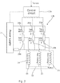
Figure 3 is a diagram showing schematically the control circuit, drive stage and motor of the EPAS system ofFigure 2 ; -
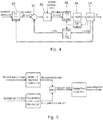
Figure 4 is a flowchart showing the calculations carried out by the control circuit ofFigure 3 ; -
Figure 5 is a further flowchart showing the calculation of the phase voltage limit by the control circuit ofFigure 3 ; -
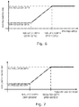
Figure 6 is a graph showing the mapping which produces the first modified modulation index; -
Figure 7 is a graph showing the mapping which produces the second modified modulation index; and -
Figure 8 is a graph showing the overall modified modulation index determined as a minimum of the first and second modulation indices shown inFigures 6 and 7 . - As shown in
Figure 1 a vehicle is provided with an electric power assisted steering (EPAS) system that draws current ibattery from the vehicle electrical supply acrosspower rail 2. The supply comprises abattery 3, typically rated at 12 volts DC, which is in turn topped up by an alternator 4. The battery also provides current to other vehicle accessories 5. - The
EPAS system 1 is shown schematically inFigure 2 of the drawings. It includes asteering column 10 attached to asteering wheel 11, atorque sensor 12 which measures the torque applied to thesteering column 10 by the driver as they turn the steering wheel, a motor control and drivecircuit 13 and anelectric motor 14. - The
torque sensor 12 may be attached to a quill shaft in series with thecolumn 10, and themotor 14 may act upon the steering column or other part of the steering system, typically through agearbox 15. - The
motor 14 typically comprises a three phase wound stator element and a rotor having for example six embedded magnets within it which in this instance are arranged so as to provide six poles which alternate between north and south around the rotor. The rotor therefore defines three direct or d axes evenly spaced around the rotor and three quadrature or q axes interspaced between the d axes. The d axes are aligned with the magnetic poles of the magnets where the lines of magnetic flux from the rotor are in the radial direction, and the q axes are spaced between the d axes where the lines of magnetic flux from the rotor are in the tangential direction. - The three
motor stator windings 21 are connected in a star network, with one end of each phase connected to aneutral point 22, and the others to thetransistor bridge drive circuit part 13b of the control and drivecircuit 13 comprises a three phase bridge forming a switching stage. Each arm of the bridge comprises a pair of switches in the form of atop transistor 20a and abottom transistor 20b connected in series between thebattery supply rail 2 and ground line. The motor windings are each tapped off from between a respective complementary pair of transistors. The transistors are turned on and off in a controlled manner by a control and drive circuit to provide pulse width modulation (PWM) of the potential applied to each of the terminals, thereby to control the potential difference applied across each of the windings and hence also the current flowing through the windings which depends on the duty cycle d for eachphase 21 of the motor. This in turn controls the strength and orientation of the magnetic field produced by the windings, and in turn the motor torque. - The torque signal output from the
torque sensor 12 is fed to an input of the motor control means 13a of the control and drivecircuit 13 which produces a set of motor current demand signals. The demand signals are in the form of two current demand signals in the d-q axis reference frame. The value of the d axis and q axis demand signals is dependent upon the measured torque and is set according to an assistance torque strategy. This can be implemented using a look up table perhaps stored in a memory of the control means which stores current demand signal values against torque signal values. - The drive circuit converts the d-q axis currents output from the control means into three current demand components in a static reference frame, one for each phase of the motor a, b or c. These demand currents are then converted by the drive circuit, in combination with an estimate of the rotor position, into suitable PWM signals that are supplied to the switching motor phases by PWM of the switches. A range of PWM switching strategies are known in the art and so will not be described in detail here. The switch arrangement is well known and described in such documents as
EP 1083650A2 , and is depicted generally inFigure 4 . - Both the control means part and drive circuit part of the control and drive circuit may be implemented using an electronic control unit running software that is stored in an area of memory.
- In order to prevent an undesirably large voltage being drawn from the alternator 4 should the
battery 3 be entirely depleted or even disconnected, themotor control circuit 13a can function as shown inFigure 4 of the accompanying drawings. In this situation, the control signals generated by the motor are calculated in order to limit the voltage applied to eachphase 21. - Taking the flowchart in
Figure 4 of the accompanying drawings, as discussed above determines a set of currents (step 30) along the d and q axes for each phase from the torque demand based upon the steering column torque. Atstep 32, these are compared with the actual currents flowing through those axes. Atstep 34, these are integrated in a proportional integrator (PI) circuit, whose output is the desired voltages (in the present case, along the d-q axes). However, a limit is applied in thePI circuit 34, which depends upon the voltage on thepower rail 2. - This limit is calculated by modifying the modulation index used to calculate the desired voltages. The modulation index is used to determine the maximum voltage available to each phase. Typically, previously, the maximum voltage that could be applied to a given phase is ½VPSM, where VPS is the nominal voltage of the power supply (typically 12 volts in an automotive environment) and M is the modulation index. For a star-wound motor as in this embodiment, the maximum voltage available across one
phase 21 is two thirds of the power supply voltage (representing the situation where thetop transistor 20a is on and thebottom transistor 20b is off, and thetop transistors 20a for the other two phases are off and thebottom transistors 20b are on), so M is
- By modifying the modulation index to be less than the previously used constant value, the maximum voltage applied to each phase can be reduced without affecting as badly the stall torque of the motor as if the current per phase was limited.
- As such, two modulations indices are calculated. The first is determined from the voltage on the
supply rail 2, which supplies thedrive circuit 13b. An example map of the first modified modulation index used against the voltage on the supply rail 2 (shown as drive stage voltage) can be seen inFigure 6 of the accompanying drawings. In this, the first modified modulation index is constant above an upper voltage MODULATION DEPTH UPPER VOLTAGE, and would take its customary value of (for this motor arrangement) say 1.15, depicted here as MAX MODULATION DEPTH. A typical value for MODULATION DEPTH UPPER VOLTAGE would be around 8 volts. Below a lower voltage threshold (MODULATION DEPTH LOWER VOLTAGE, say around 10 volts), the first modified modulation index would be a constant MIN MODULATION DEPTH, such that the system still attempts to provide some assistance even at low voltages. Between those voltages, the first modified modulation index changes linearly from the MIN MODULATION DEPTH to the MAX MODULATION DEPTH. However, it is envisaged that the variation could involve linear interpolation between several fixed points, or an entirely non linear variation. - A second modified modulation index is calculated in accordance with the graph shown in
Figure 7 of the accompanying drawings. This uses the GRADIENT LIMIT SET POINT to modify the modulation index. The GRADIENT LIMIT SET POINT indicates the maximum desired rate of change of the current taken from thepower supply rail 2, and is discussed in further detail in our United Kingdom Patent Application number1218674.8 
- The modified modulation index used is, as shown in
Figure 5 of the accompanying drawings, the minimum of the first and second modulation indices. This is depicted inFigure 8 of the accompanying drawings, where the long dashed lines show the change of the first modified modulation index with time, the shorter dashed lines show the change of the second modified modulation index with time, and the solid line depicts the overall modified modulation index, following the lower of the two dashed lines. As can be see, using the overall modulation index follows the second modified modulation index as it exits the power limitation mode (where the modified modulation index is less than its maximum) more gentle than if it were merely following the first modified modulation index, and so allows for regulation of any adverse steering feel effects. - The modified modulation index is used to determine the maximum phase voltage (still using the nominal power supply voltage), which can then be used to calculate the demanded d-q axis voltages in the
PI circuit 34. - These demand voltages are then converted to phase voltages in
conversion step 36, and converted from phase voltages to a pulse width modulation ratio for each phase atstep 38. - By providing the limitation on the phase voltage and so the power consumed by each phase, the power output is limited, reducing the strain placed on the alternator when the battery is not providing power (and therefore potentially allowing all the other electrical devices to operate correctly). The system is self regulating, reducing power output to the point where the battery voltage may recover. The fast transient response found with the scheme we previously proposed where rate of change of current was limited is achieved by limiting the power output of the motor. Other control schemes have been found to be not quick enough. The controlled exit condition from the power limitation mode allows good steer-feel to be maintained. A controlled exit condition (slowing the return to full power) maintains protection of the vehicle electrical system and provides more time for recovery. Further drops in voltage (which are likely with the vehicle operating in this state) would be less severe (as a gradient limit would be maintained); therefore subsequently the overall control of the vehicle is improved.
Claims (10)
- A method of controlling a motor (14) of an electric power assisted steering system, the motor (14) having a plurality of phases (21), the method comprising taking as an input an input signal indicative of a desired assistance torque and determining from the desired assistance torque a voltage to be applied to each of the phases (21) of the motor (14), characterized in that the step of determining the voltage to be applied to each of the phases (21) comprises limiting the voltage determined to be applied to each of the phases (21) of the motor (14) dependent upon the voltage provided by a power supply (2) to the motor (14),
in which the step of limiting the voltage applied to each phase (21) comprises the step of determining a limit to the potential difference applied across each phase
in which the limit is provided as a factor indicative of a maximum proportion of the voltage of the power supply (2),
and in which the method comprises determining a maximum modulation depth, and applying the factor to the modulation depth to create a modified modulation depth which takes into account the limit on the voltages;
the method comprising limiting the voltage determined to be applied to each of the phases (21) of the motor (14) dependent upon a desired maximum rate of change of battery current;
in which the voltage limit is the minimum of a term dependent upon the voltage of the power supply (2) and a term dependent upon the desired maximum rate of change of battery current. - The method of claim 1, in which the power supply (2) comprises at least one of a vehicle alternator (4) and a vehicle battery (3).
- The method of claim 2, in which the power supply comprises both alternator (4) and battery (3), but the battery (3) has failed or has been disconnected.
- The method of any preceding, in which this factor varies from a lower limit at a first voltage of the power supply (2) to a higher limit at a second voltage of the power supply (2) higher than the first voltage.
- The method of any preceding claim, in which the signal indicative of the desired assistance torque represents a desired motor current.
- The method of any preceding claim, in which the motor (14) is provided with a control circuit (13a) and a drive stage (13b), the drive stage (13b) comprising switches (20a, 20b) arranged to switch the voltage from the power supply (2) to the phases (21) as instructed by the control circuit (13a), in which the voltage provided by the power supply (2) on the basis of which the limit on the voltages is determined is the voltage provided to the drive stage (13b).
- A control circuit (13a) for a motor (14), the motor (14) having a plurality of phases (21), the control circuit (13a) comprising an input for a desired assistance torque and an output for control signals to be applied to switches (20a, 20b) of a drive stage (13b) for the motor, the control circuit (13a) also having an input for a power supply voltage to be applied to the motor (14), the control circuit (13a) comprising a processor arranged to take the input signal indicative of a desired assistance torque and determining from the desired assistance torque a voltage to be applied to each of the phases (21) of the motor (14) and so provide the control signals, characterized in that the processor determines the voltage to be applied to each of the phases (21) by limiting the voltage determined to be applied to each of the phases (21) of the motor dependent upon the power supply voltage by:determining a limit to the potential difference applied across each phase, the limit being provided as a factor indicative of a maximum proportion of the voltage of the power supply (2);determining a maximum modulation depth, and applying the factor to the modulation depth to create a modified modulation depth which takes into account the limit on the voltages; andlimiting the voltage determined to be applied to each of the phases (21) of the motor (14) dependent upon a desired maximum rate of change of battery current;in which the voltage limit is the minimum of a term dependent upon the voltage of the power supply (2) and a term dependent upon the desired maximum rate of change of battery current.
- A combination circuit comprising the control circuit (13a) of claim 9 and a drive stage (13b) for the motor (14), the drive stage (13b) comprising a plurality of switches (20a, 20b) arranged to switch the power supply voltage to the phases (21) of the motor (14) dependent upon the control signals from the control circuit (13a).
- A combination of a motor (14) having a plurality of phases (21) and the combination circuit of claim 10, the switches (20a, 20b) being coupled to the phases (21) of the motor (14).
- An electric power assisted steering system, comprising a steering mechanism and the combination of claim 11, the motor (14) being coupled to the steering mechanism to provide an assistance torque.
Applications Claiming Priority (2)
| Application Number | Priority Date | Filing Date | Title |
|---|---|---|---|
| GBGB1308249.0A GB201308249D0 (en) | 2013-05-08 | 2013-05-08 | Method of controlling a motor of an electric power assisted steering system |
| PCT/GB2014/051401 WO2014181109A1 (en) | 2013-05-08 | 2014-05-08 | Method of controlling a motor of an electric power assisted steering system |
Publications (2)
| Publication Number | Publication Date |
|---|---|
| EP2994997A1 EP2994997A1 (en) | 2016-03-16 |
| EP2994997B1 true EP2994997B1 (en) | 2019-08-14 |
Family
ID=48627442
Family Applications (1)
| Application Number | Title | Priority Date | Filing Date |
|---|---|---|---|
| EP14731318.3A Active EP2994997B1 (en) | 2013-05-08 | 2014-05-08 | Method of controlling a motor of an electric power assisted steering system |
Country Status (6)
| Country | Link |
|---|---|
| US (1) | US10780913B2 (en) |
| EP (1) | EP2994997B1 (en) |
| KR (1) | KR20160016793A (en) |
| CN (1) | CN105359407B (en) |
| GB (1) | GB201308249D0 (en) |
| WO (1) | WO2014181109A1 (en) |
Families Citing this family (30)
| Publication number | Priority date | Publication date | Assignee | Title |
|---|---|---|---|---|
| WO2015048959A1 (en) * | 2013-10-01 | 2015-04-09 | Continental Teves Ag & Co. Ohg | Method and device for an automatic steering intervention |
| CN109314483B (en) * | 2016-06-07 | 2020-01-31 | 日本精工株式会社 | Motor control device, and electric power steering device and vehicle equipped with same |
| JP6722355B2 (en) | 2017-03-07 | 2020-07-15 | コンチネンタル オートモーティヴ ゲゼルシャフト ミット ベシュレンクテル ハフツングContinental Automotive GmbH | Apparatus and method for detecting manual steering wheel operation |
| GB201719771D0 (en) * | 2017-11-28 | 2018-01-10 | Trw Ltd | Control circuit for a multi-phase motor |
| KR102783720B1 (en) | 2018-03-19 | 2025-03-18 | 툴라 이테크놀로지 아이엔씨. | Pulse electric machine control |
| US12609646B2 (en) | 2018-03-19 | 2026-04-21 | Tula eTechnology, Inc. | Boosted converter for pulsed electric machine control |
| US10944352B2 (en) | 2018-03-19 | 2021-03-09 | Tula eTechnology, Inc. | Boosted converter for pulsed electric machine control |
| US11623529B2 (en) | 2018-03-19 | 2023-04-11 | Tula eTechnology, Inc. | Pulse modulated control with field weakening for improved motor efficiency |
| US12311772B2 (en) | 2018-03-19 | 2025-05-27 | Tula eTechnology, Inc. | Pulse modulated control with field weakening for improved machine efficiency |
| KR102572957B1 (en) * | 2018-05-29 | 2023-09-01 | 에이치엘만도 주식회사 | Apparatus and Method for Controlling of Steer by Wire System |
| CN108768236A (en) * | 2018-06-07 | 2018-11-06 | 深圳市道通智能航空技术有限公司 | Motor control method, device, electron speed regulator and unmanned vehicle |
| DE102021101238B3 (en) * | 2021-01-21 | 2021-12-09 | Bayerische Motoren Werke Aktiengesellschaft | Method for operating an electromechanical steering support device of a vehicle |
| US11628730B2 (en) * | 2021-01-26 | 2023-04-18 | Tula eTechnology, Inc. | Pulsed electric machine control |
| US12319147B2 (en) | 2021-01-26 | 2025-06-03 | Tula eTechnology, Inc. | Pulsed electric machine control |
| US11637513B2 (en) | 2021-03-15 | 2023-04-25 | Tula eTechnology, Inc. | Methods of optimizing waveforms for electric motors |
| WO2022265986A1 (en) | 2021-06-14 | 2022-12-22 | Tula eTechnology, Inc. | Electric machines with efficient torque transitions |
| KR20240025508A (en) | 2021-06-28 | 2024-02-27 | 툴라 이테크놀로지 아이엔씨. | Selective phase control of electrical machines |
| US11557996B1 (en) | 2021-07-08 | 2023-01-17 | Tula eTechnology, Inc. | Methods of reducing vibrations for electric motors |
| US11345241B1 (en) | 2021-08-12 | 2022-05-31 | Tula eTechnology, Inc. | Method of optimizing system efficiency for battery powered electric motors |
| KR20240087822A (en) | 2021-09-08 | 2024-06-19 | 툴라 이테크놀로지 아이엔씨. | Electromechanical torque adjustment based on waveform integer multiples |
| US12617288B2 (en) | 2021-09-08 | 2026-05-05 | Tula eTechnology, Inc. | Electric machine torque adjustment based on waveform multiples |
| US12328088B2 (en) | 2021-10-11 | 2025-06-10 | Tula eTechnology, Inc. | Pulsed control of multiple electric machines |
| WO2023069131A1 (en) | 2021-10-18 | 2023-04-27 | Tula eTechnology, Inc. | Mechanical and electromechanical arrangements for field-weakening of an electric machine that utilizes permanent magnets |
| EP4497197A4 (en) | 2022-03-22 | 2026-02-18 | Tula Technology Inc | DELAY REDUCTION FOR SYNCHRONOUS MACHINES WITH PULSE WINDING FIELD |
| KR20250034022A (en) | 2022-07-08 | 2025-03-10 | 툴라 이테크놀로지 아이엔씨. | Electromechanical drive calibration, verification and efficiency improvement |
| US12244250B2 (en) | 2022-07-18 | 2025-03-04 | Tula eTechnology, Inc. | Feedback scaling for electric machines |
| US11888424B1 (en) | 2022-07-18 | 2024-01-30 | Tula eTechnology, Inc. | Methods for improving rate of rise of torque in electric machines with stator current biasing |
| US12424962B2 (en) | 2022-07-18 | 2025-09-23 | Tula eTechnology, Inc. | Pulsed electric machine control with soft start and end |
| JP2025528312A (en) | 2022-08-22 | 2025-08-28 | トゥラ イーテクノロジー,インコーポレイテッド | Boost rotor supply circuit and method for improving efficiency of pulsed electric machines - Patents.com |
| US12370907B2 (en) | 2023-10-17 | 2025-07-29 | Tula eTechnology, Inc. | On-pulse transition times for pulsed controlled electric machines using boost voltages |
Family Cites Families (18)
| Publication number | Priority date | Publication date | Assignee | Title |
|---|---|---|---|---|
| JPH0615331B2 (en) | 1985-06-12 | 1994-03-02 | 株式会社日立製作所 | Electric power steering device |
| US4751978A (en) * | 1987-03-16 | 1988-06-21 | Trw Inc. | Electric assist steering system with alternator power source |
| JPH0530485U (en) * | 1991-09-28 | 1993-04-23 | 光洋精工株式会社 | Vane pump |
| JP4856383B2 (en) * | 2005-03-18 | 2012-01-18 | 本田技研工業株式会社 | Electric power steering device |
| JP2007236075A (en) * | 2006-02-28 | 2007-09-13 | Mitsubishi Electric Corp | Electric power steering control device |
| JP5034375B2 (en) * | 2006-08-25 | 2012-09-26 | 日本精工株式会社 | Electric power steering device |
| JP4730280B2 (en) * | 2006-10-23 | 2011-07-20 | トヨタ自動車株式会社 | Vehicle power supply control device |
| DE602008000946D1 (en) * | 2007-07-10 | 2010-05-20 | Jtekt Corp | Motor controller |
| JP5351002B2 (en) | 2009-12-10 | 2013-11-27 | 三菱電機株式会社 | Motor control device |
| GB201000948D0 (en) * | 2010-01-21 | 2010-03-10 | Trw Ltd | Controllers for and methods of controlling electric power assisted steering systems |
| JP2011205838A (en) | 2010-03-26 | 2011-10-13 | Omron Automotive Electronics Co Ltd | Motor drive |
| WO2011142032A1 (en) | 2010-05-14 | 2011-11-17 | 三菱電機株式会社 | Brushless-motor drive apparatus |
| GB201013957D0 (en) * | 2010-08-20 | 2010-10-06 | Trw Ltd | Measurement circuit |
| JP5353867B2 (en) * | 2010-12-02 | 2013-11-27 | 株式会社デンソー | Rotating machine control device |
| JP5161985B2 (en) * | 2011-02-16 | 2013-03-13 | 三菱電機株式会社 | Power conversion device and control device for electric power steering |
| CN103442967B (en) | 2011-03-17 | 2015-11-25 | 丰田自动车株式会社 | Driven steering device |
| US9595902B2 (en) * | 2011-08-03 | 2017-03-14 | GM Global Technology Operations LLC | Methods, systems and apparatus for adjusting modulation index to improve linearity of phase voltage commands |
| JP5811363B2 (en) * | 2013-03-13 | 2015-11-11 | 株式会社デンソー | Rotating electrical machine control device and electric power steering device using the same |
-
2013
- 2013-05-08 GB GBGB1308249.0A patent/GB201308249D0/en not_active Ceased
-
2014
- 2014-05-08 US US14/889,493 patent/US10780913B2/en active Active
- 2014-05-08 CN CN201480025703.8A patent/CN105359407B/en active Active
- 2014-05-08 KR KR1020157033230A patent/KR20160016793A/en not_active Ceased
- 2014-05-08 EP EP14731318.3A patent/EP2994997B1/en active Active
- 2014-05-08 WO PCT/GB2014/051401 patent/WO2014181109A1/en not_active Ceased
Non-Patent Citations (1)
| Title |
|---|
| None * |
Also Published As
| Publication number | Publication date |
|---|---|
| KR20160016793A (en) | 2016-02-15 |
| GB201308249D0 (en) | 2013-06-12 |
| US20160114830A1 (en) | 2016-04-28 |
| US10780913B2 (en) | 2020-09-22 |
| CN105359407B (en) | 2019-06-04 |
| WO2014181109A1 (en) | 2014-11-13 |
| EP2994997A1 (en) | 2016-03-16 |
| CN105359407A (en) | 2016-02-24 |
Similar Documents
| Publication | Publication Date | Title |
|---|---|---|
| US10780913B2 (en) | Method of controlling a motor of an electric power assisted steering system | |
| US11177745B2 (en) | Electric motor apparatus | |
| US11177760B2 (en) | Electric motor apparatus | |
| EP2909072B1 (en) | Control strategy for a motor of an electric assisted steering system | |
| US7791295B2 (en) | Field weakening control apparatus for permanent magnet motor and electric power steering using same | |
| CN105471360B (en) | Motor drive control apparatus, power steering gear, electrical braking device, electric pump mechanism | |
| US7508149B2 (en) | Oil pump systems and methods for preventing torque overload in motors of oil pump systems | |
| US8862323B2 (en) | Motor control device and vehicle-steering device comprising same | |
| US10029727B2 (en) | Rotating electric machine control device | |
| US7728541B2 (en) | Electric motor drive control method and apparatus | |
| US10137929B2 (en) | Electric power steering device for vehicle | |
| US9649953B2 (en) | Method and device for operating an electric machine of a motor vehicle drive train | |
| US20090015182A1 (en) | Motor control device | |
| US20120019181A1 (en) | Power converter for rotating electric machine | |
| EP3597508A2 (en) | Motor controller | |
| JP5955209B2 (en) | Failure detection device for power conversion system | |
| JP5023718B2 (en) | VEHICLE DRIVE CONTROL DEVICE AND VEHICLE DRIVE CONTROL METHOD | |
| JP7292507B2 (en) | Motor control device and electric power steering device | |
| US11146198B2 (en) | Motor control device | |
| JP2001103783A (en) | Motor controller |
Legal Events
| Date | Code | Title | Description |
|---|---|---|---|
| PUAI | Public reference made under article 153(3) epc to a published international application that has entered the european phase |
Free format text: ORIGINAL CODE: 0009012 |
|
| 17P | Request for examination filed |
Effective date: 20151014 |
|
| AK | Designated contracting states |
Kind code of ref document: A1 Designated state(s): AL AT BE BG CH CY CZ DE DK EE ES FI FR GB GR HR HU IE IS IT LI LT LU LV MC MK MT NL NO PL PT RO RS SE SI SK SM TR |
|
| AX | Request for extension of the european patent |
Extension state: BA ME |
|
| DAX | Request for extension of the european patent (deleted) | ||
| STAA | Information on the status of an ep patent application or granted ep patent |
Free format text: STATUS: EXAMINATION IS IN PROGRESS |
|
| 17Q | First examination report despatched |
Effective date: 20170531 |
|
| GRAP | Despatch of communication of intention to grant a patent |
Free format text: ORIGINAL CODE: EPIDOSNIGR1 |
|
| STAA | Information on the status of an ep patent application or granted ep patent |
Free format text: STATUS: GRANT OF PATENT IS INTENDED |
|
| INTG | Intention to grant announced |
Effective date: 20190502 |
|
| GRAS | Grant fee paid |
Free format text: ORIGINAL CODE: EPIDOSNIGR3 |
|
| GRAA | (expected) grant |
Free format text: ORIGINAL CODE: 0009210 |
|
| STAA | Information on the status of an ep patent application or granted ep patent |
Free format text: STATUS: THE PATENT HAS BEEN GRANTED |
|
| AK | Designated contracting states |
Kind code of ref document: B1 Designated state(s): AL AT BE BG CH CY CZ DE DK EE ES FI FR GB GR HR HU IE IS IT LI LT LU LV MC MK MT NL NO PL PT RO RS SE SI SK SM TR |
|
| REG | Reference to a national code |
Ref country code: GB Ref legal event code: FG4D |
|
| REG | Reference to a national code |
Ref country code: CH Ref legal event code: EP Ref country code: AT Ref legal event code: REF Ref document number: 1168206 Country of ref document: AT Kind code of ref document: T Effective date: 20190815 |
|
| REG | Reference to a national code |
Ref country code: IE Ref legal event code: FG4D |
|
| REG | Reference to a national code |
Ref country code: DE Ref legal event code: R096 Ref document number: 602014051740 Country of ref document: DE |
|
| REG | Reference to a national code |
Ref country code: NL Ref legal event code: MP Effective date: 20190814 |
|
| REG | Reference to a national code |
Ref country code: LT Ref legal event code: MG4D |
|
| PG25 | Lapsed in a contracting state [announced via postgrant information from national office to epo] |
Ref country code: PT Free format text: LAPSE BECAUSE OF FAILURE TO SUBMIT A TRANSLATION OF THE DESCRIPTION OR TO PAY THE FEE WITHIN THE PRESCRIBED TIME-LIMIT Effective date: 20191216 Ref country code: FI Free format text: LAPSE BECAUSE OF FAILURE TO SUBMIT A TRANSLATION OF THE DESCRIPTION OR TO PAY THE FEE WITHIN THE PRESCRIBED TIME-LIMIT Effective date: 20190814 Ref country code: SE Free format text: LAPSE BECAUSE OF FAILURE TO SUBMIT A TRANSLATION OF THE DESCRIPTION OR TO PAY THE FEE WITHIN THE PRESCRIBED TIME-LIMIT Effective date: 20190814 Ref country code: BG Free format text: LAPSE BECAUSE OF FAILURE TO SUBMIT A TRANSLATION OF THE DESCRIPTION OR TO PAY THE FEE WITHIN THE PRESCRIBED TIME-LIMIT Effective date: 20191114 Ref country code: NL Free format text: LAPSE BECAUSE OF FAILURE TO SUBMIT A TRANSLATION OF THE DESCRIPTION OR TO PAY THE FEE WITHIN THE PRESCRIBED TIME-LIMIT Effective date: 20190814 Ref country code: HR Free format text: LAPSE BECAUSE OF FAILURE TO SUBMIT A TRANSLATION OF THE DESCRIPTION OR TO PAY THE FEE WITHIN THE PRESCRIBED TIME-LIMIT Effective date: 20190814 Ref country code: LT Free format text: LAPSE BECAUSE OF FAILURE TO SUBMIT A TRANSLATION OF THE DESCRIPTION OR TO PAY THE FEE WITHIN THE PRESCRIBED TIME-LIMIT Effective date: 20190814 Ref country code: NO Free format text: LAPSE BECAUSE OF FAILURE TO SUBMIT A TRANSLATION OF THE DESCRIPTION OR TO PAY THE FEE WITHIN THE PRESCRIBED TIME-LIMIT Effective date: 20191114 |
|
| REG | Reference to a national code |
Ref country code: AT Ref legal event code: MK05 Ref document number: 1168206 Country of ref document: AT Kind code of ref document: T Effective date: 20190814 |
|
| PG25 | Lapsed in a contracting state [announced via postgrant information from national office to epo] |
Ref country code: LV Free format text: LAPSE BECAUSE OF FAILURE TO SUBMIT A TRANSLATION OF THE DESCRIPTION OR TO PAY THE FEE WITHIN THE PRESCRIBED TIME-LIMIT Effective date: 20190814 Ref country code: GR Free format text: LAPSE BECAUSE OF FAILURE TO SUBMIT A TRANSLATION OF THE DESCRIPTION OR TO PAY THE FEE WITHIN THE PRESCRIBED TIME-LIMIT Effective date: 20191115 Ref country code: ES Free format text: LAPSE BECAUSE OF FAILURE TO SUBMIT A TRANSLATION OF THE DESCRIPTION OR TO PAY THE FEE WITHIN THE PRESCRIBED TIME-LIMIT Effective date: 20190814 Ref country code: AL Free format text: LAPSE BECAUSE OF FAILURE TO SUBMIT A TRANSLATION OF THE DESCRIPTION OR TO PAY THE FEE WITHIN THE PRESCRIBED TIME-LIMIT Effective date: 20190814 Ref country code: RS Free format text: LAPSE BECAUSE OF FAILURE TO SUBMIT A TRANSLATION OF THE DESCRIPTION OR TO PAY THE FEE WITHIN THE PRESCRIBED TIME-LIMIT Effective date: 20190814 Ref country code: IS Free format text: LAPSE BECAUSE OF FAILURE TO SUBMIT A TRANSLATION OF THE DESCRIPTION OR TO PAY THE FEE WITHIN THE PRESCRIBED TIME-LIMIT Effective date: 20191214 |
|
| PG25 | Lapsed in a contracting state [announced via postgrant information from national office to epo] |
Ref country code: TR Free format text: LAPSE BECAUSE OF FAILURE TO SUBMIT A TRANSLATION OF THE DESCRIPTION OR TO PAY THE FEE WITHIN THE PRESCRIBED TIME-LIMIT Effective date: 20190814 |
|
| PG25 | Lapsed in a contracting state [announced via postgrant information from national office to epo] |
Ref country code: RO Free format text: LAPSE BECAUSE OF FAILURE TO SUBMIT A TRANSLATION OF THE DESCRIPTION OR TO PAY THE FEE WITHIN THE PRESCRIBED TIME-LIMIT Effective date: 20190814 Ref country code: PL Free format text: LAPSE BECAUSE OF FAILURE TO SUBMIT A TRANSLATION OF THE DESCRIPTION OR TO PAY THE FEE WITHIN THE PRESCRIBED TIME-LIMIT Effective date: 20190814 Ref country code: AT Free format text: LAPSE BECAUSE OF FAILURE TO SUBMIT A TRANSLATION OF THE DESCRIPTION OR TO PAY THE FEE WITHIN THE PRESCRIBED TIME-LIMIT Effective date: 20190814 Ref country code: EE Free format text: LAPSE BECAUSE OF FAILURE TO SUBMIT A TRANSLATION OF THE DESCRIPTION OR TO PAY THE FEE WITHIN THE PRESCRIBED TIME-LIMIT Effective date: 20190814 Ref country code: IT Free format text: LAPSE BECAUSE OF FAILURE TO SUBMIT A TRANSLATION OF THE DESCRIPTION OR TO PAY THE FEE WITHIN THE PRESCRIBED TIME-LIMIT Effective date: 20190814 Ref country code: DK Free format text: LAPSE BECAUSE OF FAILURE TO SUBMIT A TRANSLATION OF THE DESCRIPTION OR TO PAY THE FEE WITHIN THE PRESCRIBED TIME-LIMIT Effective date: 20190814 |
|
| PG25 | Lapsed in a contracting state [announced via postgrant information from national office to epo] |
Ref country code: SK Free format text: LAPSE BECAUSE OF FAILURE TO SUBMIT A TRANSLATION OF THE DESCRIPTION OR TO PAY THE FEE WITHIN THE PRESCRIBED TIME-LIMIT Effective date: 20190814 Ref country code: CZ Free format text: LAPSE BECAUSE OF FAILURE TO SUBMIT A TRANSLATION OF THE DESCRIPTION OR TO PAY THE FEE WITHIN THE PRESCRIBED TIME-LIMIT Effective date: 20190814 Ref country code: SM Free format text: LAPSE BECAUSE OF FAILURE TO SUBMIT A TRANSLATION OF THE DESCRIPTION OR TO PAY THE FEE WITHIN THE PRESCRIBED TIME-LIMIT Effective date: 20190814 Ref country code: IS Free format text: LAPSE BECAUSE OF FAILURE TO SUBMIT A TRANSLATION OF THE DESCRIPTION OR TO PAY THE FEE WITHIN THE PRESCRIBED TIME-LIMIT Effective date: 20200224 |
|
| REG | Reference to a national code |
Ref country code: DE Ref legal event code: R097 Ref document number: 602014051740 Country of ref document: DE |
|
| PLBE | No opposition filed within time limit |
Free format text: ORIGINAL CODE: 0009261 |
|
| STAA | Information on the status of an ep patent application or granted ep patent |
Free format text: STATUS: NO OPPOSITION FILED WITHIN TIME LIMIT |
|
| PG2D | Information on lapse in contracting state deleted |
Ref country code: IS |
|
| 26N | No opposition filed |
Effective date: 20200603 |
|
| PG25 | Lapsed in a contracting state [announced via postgrant information from national office to epo] |
Ref country code: SI Free format text: LAPSE BECAUSE OF FAILURE TO SUBMIT A TRANSLATION OF THE DESCRIPTION OR TO PAY THE FEE WITHIN THE PRESCRIBED TIME-LIMIT Effective date: 20190814 |
|
| PG25 | Lapsed in a contracting state [announced via postgrant information from national office to epo] |
Ref country code: CH Free format text: LAPSE BECAUSE OF NON-PAYMENT OF DUE FEES Effective date: 20200531 Ref country code: MC Free format text: LAPSE BECAUSE OF FAILURE TO SUBMIT A TRANSLATION OF THE DESCRIPTION OR TO PAY THE FEE WITHIN THE PRESCRIBED TIME-LIMIT Effective date: 20190814 Ref country code: LI Free format text: LAPSE BECAUSE OF NON-PAYMENT OF DUE FEES Effective date: 20200531 |
|
| REG | Reference to a national code |
Ref country code: BE Ref legal event code: MM Effective date: 20200531 |
|
| PG25 | Lapsed in a contracting state [announced via postgrant information from national office to epo] |
Ref country code: LU Free format text: LAPSE BECAUSE OF NON-PAYMENT OF DUE FEES Effective date: 20200508 |
|
| PG25 | Lapsed in a contracting state [announced via postgrant information from national office to epo] |
Ref country code: IE Free format text: LAPSE BECAUSE OF NON-PAYMENT OF DUE FEES Effective date: 20200508 Ref country code: FR Free format text: LAPSE BECAUSE OF NON-PAYMENT OF DUE FEES Effective date: 20200531 |
|
| PG25 | Lapsed in a contracting state [announced via postgrant information from national office to epo] |
Ref country code: BE Free format text: LAPSE BECAUSE OF NON-PAYMENT OF DUE FEES Effective date: 20200531 |
|
| PG25 | Lapsed in a contracting state [announced via postgrant information from national office to epo] |
Ref country code: MT Free format text: LAPSE BECAUSE OF FAILURE TO SUBMIT A TRANSLATION OF THE DESCRIPTION OR TO PAY THE FEE WITHIN THE PRESCRIBED TIME-LIMIT Effective date: 20190814 Ref country code: CY Free format text: LAPSE BECAUSE OF FAILURE TO SUBMIT A TRANSLATION OF THE DESCRIPTION OR TO PAY THE FEE WITHIN THE PRESCRIBED TIME-LIMIT Effective date: 20190814 |
|
| PG25 | Lapsed in a contracting state [announced via postgrant information from national office to epo] |
Ref country code: MK Free format text: LAPSE BECAUSE OF FAILURE TO SUBMIT A TRANSLATION OF THE DESCRIPTION OR TO PAY THE FEE WITHIN THE PRESCRIBED TIME-LIMIT Effective date: 20190814 |
|
| P01 | Opt-out of the competence of the unified patent court (upc) registered |
Effective date: 20230628 |
|
| PGFP | Annual fee paid to national office [announced via postgrant information from national office to epo] |
Ref country code: GB Payment date: 20240314 Year of fee payment: 11 |
|
| PGFP | Annual fee paid to national office [announced via postgrant information from national office to epo] |
Ref country code: DE Payment date: 20250311 Year of fee payment: 12 |
|
| GBPC | Gb: european patent ceased through non-payment of renewal fee |
Effective date: 20250508 |
|
| PG25 | Lapsed in a contracting state [announced via postgrant information from national office to epo] |
Ref country code: GB Free format text: LAPSE BECAUSE OF NON-PAYMENT OF DUE FEES Effective date: 20250508 |