EP2994595B1 - Expandierbare abgerundete anordnung zur verwendung mit einer bohrlochdeflektoranordnung - Google Patents
Expandierbare abgerundete anordnung zur verwendung mit einer bohrlochdeflektoranordnung Download PDFInfo
- Publication number
- EP2994595B1 EP2994595B1 EP13890229.1A EP13890229A EP2994595B1 EP 2994595 B1 EP2994595 B1 EP 2994595B1 EP 13890229 A EP13890229 A EP 13890229A EP 2994595 B1 EP2994595 B1 EP 2994595B1
- Authority
- EP
- European Patent Office
- Prior art keywords
- bullnose
- length
- assembly
- tip
- deflector
- Prior art date
- Legal status (The legal status is an assumption and is not a legal conclusion. Google has not performed a legal analysis and makes no representation as to the accuracy of the status listed.)
- Active
Links
Images


Classifications
-
- E—FIXED CONSTRUCTIONS
- E21—EARTH OR ROCK DRILLING; MINING
- E21B—EARTH OR ROCK DRILLING; OBTAINING OIL, GAS, WATER, SOLUBLE OR MELTABLE MATERIALS OR A SLURRY OF MINERALS FROM WELLS
- E21B7/00—Special methods or apparatus for drilling
- E21B7/04—Directional drilling
- E21B7/06—Deflecting the direction of boreholes
- E21B7/061—Deflecting the direction of boreholes the tool shaft advancing relative to a guide, e.g. a curved tube or a whipstock
-
- E—FIXED CONSTRUCTIONS
- E21—EARTH OR ROCK DRILLING; MINING
- E21B—EARTH OR ROCK DRILLING; OBTAINING OIL, GAS, WATER, SOLUBLE OR MELTABLE MATERIALS OR A SLURRY OF MINERALS FROM WELLS
- E21B41/00—Equipment or details not covered by groups E21B15/00 - E21B40/00
- E21B41/0035—Apparatus or methods for multilateral well technology, e.g. for the completion of or workover on wells with one or more lateral branches
-
- E—FIXED CONSTRUCTIONS
- E21—EARTH OR ROCK DRILLING; MINING
- E21B—EARTH OR ROCK DRILLING; OBTAINING OIL, GAS, WATER, SOLUBLE OR MELTABLE MATERIALS OR A SLURRY OF MINERALS FROM WELLS
- E21B17/00—Drilling rods or pipes; Flexible drill strings; Kellies; Drill collars; Sucker rods; Cables; Casings; Tubings
- E21B17/18—Pipes provided with plural fluid passages
-
- E—FIXED CONSTRUCTIONS
- E21—EARTH OR ROCK DRILLING; MINING
- E21B—EARTH OR ROCK DRILLING; OBTAINING OIL, GAS, WATER, SOLUBLE OR MELTABLE MATERIALS OR A SLURRY OF MINERALS FROM WELLS
- E21B23/00—Apparatus for displacing, setting, locking, releasing or removing tools, packers or the like in boreholes or wells
- E21B23/08—Introducing or running tools by fluid pressure, e.g. through-the-flow-line tool systems
- E21B23/12—Tool diverters
Definitions
- the present disclosure relates generally to multilateral wellbores and, more particularly, to an adjustable bullnose assembly that works with a deflector assembly to allow entry into more than one lateral wellbore of a multilateral wellbore.
- Hydrocarbons can be produced through relatively complex wellbores traversing a subterranean formation.
- Some wellbores include one or more lateral wellbores that extend at an angle from a parent or main wellbore. Such wellbores are commonly called multilateral wellbores.
- Various devices and downhole tools can be installed in a multilateral wellbore in order to direct assemblies toward a particular lateral wellbore.
- a deflector for example, is a device that can be positioned in the main wellbore at a junction and configured to direct a bullnose assembly conveyed downhole toward a lateral wellbore. Depending on various parameters of the bullnose assembly, some deflectors also allow the bullnose assembly to remain within the main wellbore and otherwise bypass the junction without being directed into the lateral wellbore.
- US 2005/061511 A1 discloses a high pressure multiple branch wellbore junction
- US 2005/230151 A1 discloses an apparatus and method for opening and closing lateral boreholes.
- the present disclosure relates generally to multilateral wellbores and, more particularly, to an adjustable bullnose assembly that works with a deflector assembly to allow entry into more than one lateral wellbore of a multilateral wellbore.
- the present disclosure describes embodiments of an exemplary bullnose assembly that is able to adjust its length while downhole in a multilateral wellbore. This may prove advantageous for well operators since the variable length bullnose assembly may be able to be conveyed downhole and bypass one or more deflector assemblies until reaching a desired deflector assembly. At the desired deflector assembly, the variable length bullnose assembly may be actuated to alter its length such that it may be deflected by the deflector assembly into a desired lateral wellbore. Such length variability in the bullnose assembly may allow a single bullnose assembly to enter several different lateral boreholes in a stacked multilateral well having several junctions all in one trip downhole.
- the deflector assembly 100 may be arranged within or otherwise form an integral part of a tubular string 102.
- the tubular string 102 may be a casing string used to line the inner wall of a wellbore drilled into a subterranean formation.
- the tubular string 102 may be a work string extended downhole within the wellbore or the casing that lines the wellbore.
- the deflector assembly 100 may be generally arranged within a parent or main bore 104 at or otherwise uphole from a junction 106 where a lateral bore 108 extends from the main bore 104.
- the lateral bore 108 may extend into a lateral wellbore (not shown) drilled at an angle away from the parent or main bore 104.
- the deflector assembly 100 may include a first or upper deflector 110a and a second or lower deflector 110b.
- the upper and lower deflectors 110a,b may be secured within the tubular string 102 using one or more mechanical fasteners (not shown) and the like.
- the upper and lower deflectors 110a,b may be welded into place within the tubular string 102, without departing from the scope of the disclosure.
- the upper and lower deflectors 110a,b may form an integral part of the tubular string 102, such as being machined out of bar stock and threaded into the tubular string 102.
- the upper deflector 110a may be arranged closer to the surface (not shown) than the lower deflector 110b, and the lower deflector 110 may be generally arranged at or adjacent the junction 106.
- the upper deflector 110a may define or otherwise provide a ramped surface 112 facing toward the uphole direction within the main bore 104.
- the upper deflector 110a may further define a first channel 114a and a second channel 114b, where both the first and second channels 114a,b extend longitudinally through the upper deflector 110a.
- the lower deflector 110b may define a first conduit 116a and a second conduit 116b, where both the first and second conduits 116a,b extend longitudinally through the lower deflector 110b.
- the second conduit 116b extends into and otherwise feeds the lateral bore 108 while the first conduit 116a continues downhole and is otherwise configured to extend the parent or main bore 104 past the junction 106.
- the deflector assembly 100 may be arranged in a multilateral wellbore system where the lateral bore 108 is only one of several lateral bores that are accessible from the main bore 104 via a corresponding number of deflector assemblies 100 arranged at multiple junctions.
- the deflector assembly 100 may be useful in directing a bullnose assembly (not shown) into the lateral bore 108 via the second conduit 116b based on a length of the bullnose assembly. If the length of the bullnose assembly does not meet particular length requirements or parameters, it will instead be directed further downhole in the main bore 104 via the first conduit 116a.
- the first deflector 110a may be separated from the second deflector 110b within the main bore 104 by a distance 202.
- the distance 202 may be a predetermined distance that allows a bullnose assembly that is as long as or longer than the distance 202 to be directed into the lateral bore 108 via the second conduit 116b. If the length of the bullnose assembly is shorter than the distance 202, however, the bullnose assembly will remain in the main bore 104 and be directed further downhole via the first conduit 116a.
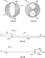
- FIGS. 3A and 3B illustrated are cross-sectional end views of the upper and lower deflectors 110a,b, respectively, according to one or more embodiments.
- the first channel 114a and the second channel 114b are shown as extending longitudinally through the upper deflector 110a.
- the first channel 114a may exhibit a first width 302a and the second channel 114b may exhibit a second width 302b, where the second width 302b is also equivalent to a diameter of the second channel 114b.
- the first width 302a is less than the second width 302b.
- bullnose assemblies exhibiting a diameter larger than the first width 302a but smaller than the second width 302b may be able to extend through the upper deflector 110a via the second channel 114b and otherwise bypass the first channel 114a.
- bullnose assemblies exhibiting a diameter smaller than the first width 302a may be able to pass through the upper deflector 110a via the first or second channels 114a,b.
- the first and second conduits 116a,b are shown as extending longitudinally through the lower deflector 110b.
- the first conduit 116a may exhibit a first diameter 304a and the second conduit 116b may exhibit a second diameter 304b.
- the first and second diameters 304a,b may be the same or substantially the same. In other embodiments, the first and second diameters 304a,b may be different. In either case, the first and second diameters 304a,b may be large enough and otherwise configured to receive a bullnose assembly therethrough after the bullnose assembly has passed through the upper deflector 110a ( FIG. 3A ).
- the bullnose assemblies 402a,b may constitute the distal end of a tool string (not shown), such as a bottom hole assembly or the like, that is conveyed downhole within the main wellbore 104 ( FIGS. 1-2 ) from a well surface (not shown).
- a tool string such as a bottom hole assembly or the like
- the bullnose assemblies 402a,b and related tool strings are conveyed downhole using coiled tubing (not shown).
- the bullnose assemblies 402a,b and related tool strings may be conveyed downhole using other types of conveyances such as, but not limited to, drill pipe, production tubulars, or any conduit capable of conveying fluid pressure.
- the bullnose assemblies 402a,b and related tool strings may be conveyed downhole using wireline, slickline, electric line, etc, without departing from the scope of the disclosure.
- the tool string may include various downhole tools and devices configured to perform or otherwise undertake various wellbore operations once accurately placed in the downhole environment.
- the bullnose assemblies 402a,b may be configured to accurately guide the tool string downhole such that it reaches its target destination, e.g ., the lateral bore 108 of FIGS. 1-2 or further downhole within the main bore 104.
- each bullnose assembly 402a,b may include a body 404 and a bullnose tip 406 coupled or otherwise attached to the distal end of the body 404.
- the bullnose tip 406 may form an integral part of the body 404 as an integral extension thereof.
- the bullnose tip 406 may be rounded off at its end or otherwise angled or arcuate such that the bullnose tip 406 does not present sharp corners or angled edges that might catch on portions of the main bore 104 as it is extended downhole.
- the bullnose tip 406 of the first bullnose assembly 402a exhibits a first length 408a and the bullnose tip 406 of the second bullnose assembly 402b exhibits a second length 408b. As depicted, the first length 408a is greater than the second length 408b. Moreover, the bullnose tip 406 of the first bullnose assembly 402a exhibits a first diameter 410a and the bullnose tip 406 of the second bullnose assembly 402b exhibits a second diameter 410b. In some embodiments, the first and second diameters 410a,b may be the same or substantially the same. In other embodiments, the first and second diameters 410a,b may be different.
- first and second diameters 410a,b may be small enough and otherwise able to extend through the second width 302b ( FIG. 3A ) of the upper deflector 110a and the first and second diameters 304a,b ( FIG. 3B ) of the lower deflector 110b.
- the body 404 of the first bullnose assembly 402a exhibits a third diameter 412a and the body 404 of the second bullnose assembly 402b exhibits a fourth diameter 412b.
- the third and fourth diameters 412a,b may be the same or substantially the same. In other embodiments, the third and fourth diameters 412a,b may be different. In either case, the third and fourth diameters 412a,b may each be smaller than the first and second diameters 410a,b. Moreover, the third and fourth diameters 412a,b may be smaller than the first width 302a ( FIG. 3A ) of the upper deflector 110a and otherwise able to be received therein, as will be discussed in greater detail below.
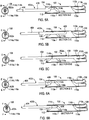
- FIGS. 5A-5C illustrated are cross-sectional views of the deflector assembly 100 as used in exemplary operation, according to one or more embodiments. More particularly, FIGS. 5A-5C illustrate progressive views of the first bullnose assembly 402a of FIG. 4A interacting with and otherwise being deflected by the deflector assembly 100 based on the parameters of the first bullnose assembly 402a. Furthermore, each of FIGS. 5A-5C provides a cross-sectional end view (on the left of each figure) and a corresponding cross-sectional side view (on the right of each figure) of the exemplary operation as it progresses.
- the first bullnose assembly 402a is extended downhole within the main bore 104 and engages the upper deflector 110a. More specifically, the diameter 410a ( FIG. 4A ) of the bullnose tip 406 may be larger than the first width 302a ( FIG. 3A ) such that the bullnose tip 406 is unable to extend through the upper deflector 110a via the first channel 114a. Instead, the bullnose tip 406 may be configured to slidingly engage the ramped surface 112 until locating the second channel 114b. Since the diameter 410a ( FIG. 4A ) of the bullnose tip 406 is smaller than the second width 302b ( FIG.
- the bullnose assembly 402a is able to extend through the upper deflector 110a via the second channel 114b. This is shown in FIG. 5B as the bullnose assembly 402a is advanced in the main bore 104 and otherwise extended at least partially through the upper deflector 110a.
- the bullnose assembly 402a is advanced further in the main bore 104 and directed into the second conduit 116b of the lower deflector 110b. This is possible since the length 408a ( FIG. 4A ) of the bullnose tip 406 is greater than the distance 202 ( FIG. 2 ) that separates the upper and lower deflectors 110a,b. In other words, since the distance 202 is less than the length 408a of the bullnose tip 406, the bullnose assembly 402a is generally prevented from moving laterally within the main bore 104 and toward the first conduit 116a of the lower deflector 110b.
- the bullnose tip 406 is received by the second conduit 116b while at least a portion of the bullnose tip 406 remains supported in the second channel 114b of the upper deflector 110a. Moreover, the second conduit 116b exhibits a diameter 304b ( FIG. 3B ) that is greater than the diameter 410a ( FIG. 4A ) of the bullnose tip 406 and can therefore guide the bullnose assembly 402a toward the lateral bore 108.
- FIGS. 6A-6D illustrated are cross-sectional views of the deflector assembly 100 as used in exemplary operation, according to one or more embodiments. More particularly, FIGS. 6A-6D illustrate progressive views of the second bullnose assembly 402b interacting with and otherwise being deflected by the deflector assembly 100. Furthermore, similar to FIGS. 5A-5C , each of FIGS. 6A-6D provides a cross-sectional end view (on the left of each figure) and a corresponding cross-sectional side view (on the right of each figure) of the exemplary operation as it progresses.
- the second bullnose assembly 402b is shown engaging the upper deflector 110a after having been extended downhole within the main bore 104. More specifically, and similar to the first bullnose assembly 402a, the diameter 410b ( FIG. 4B ) of the bullnose tip 406 may be larger than the first width 302a ( FIG. 3A ) such that the bullnose tip 406 is unable to extend through the upper deflector 110a via the first channel 114a. Instead, the bullnose tip 406 may be configured to slidingly engage the ramped surface 112 until locating the second channel 114b. Since the diameter 410b ( FIG. 4B ) of the bullnose tip 406 is smaller than the second width 302b ( FIG.
- the bullnose assembly 402b may be able to extend through the upper deflector 110a via the second channel 114b. This is shown in FIG. 6B as the bullnose assembly 402b is advanced in the main bore 104 and otherwise extended at least partially through the upper deflector 110a.
- the bullnose assembly 402b is advanced further in the main bore 104 until the bullnose tip 406 exits the second channel 114b.
- the bullnose assembly 402b may no longer be supported within the second channel 114b and may instead fall into or otherwise be received by the first channel 114a.
- the diameter 412b ( FIG. 4B ) of the body 404 of the bullnose assembly 402b is smaller than the first width 302a ( FIG. 3A ), and the length 408b ( FIG. 4B ) of the bullnose tip 406 is less than the distance 202 ( FIG. 2 ) that separates the upper and lower deflectors 110a,b.
- gravity may act on the bullnose assembly 402b and allow it to fall into the first channel 114a once the bullnose tip 406 exits the second channel 114b and no longer supports the bullnose assembly 402b.
- the bullnose assembly 402b is advanced even further in the main bore 104 until the bullnose tip 406 enters or is otherwise received within the first conduit 116a.
- the first conduit 116a exhibits a diameter 304a ( FIG. 3B ) that is greater than the diameter 410b ( FIG. 4B ) of the bullnose tip 406 and can therefore guide the bullnose assembly 402b further down the main bore 104 and otherwise not into the lateral bore 108.
- the wellbore system 700 may include a main bore 104 that extends from a surface location (not shown) and passes through at least two junctions 106 (shown as a first junction 106a and a second junction 106b). While two junctions 106a,b are shown in the wellbore system 700, it will be appreciated that more than two junctions 106a,b may be utilized, without departing from the scope of the disclosure.
- each junction 106a,b a lateral bore 108 (shown as first and second lateral bores 108a and 108b, respectively) extends from the main bore 104. Similar designs of the deflector assembly 100 of FIGS. 1 and 2 may be arranged at each junction 106a,b, shown in FIG. 7 as a first deflector assembly 100a and a second deflector assembly 100b. Accordingly, each junction 106a,b includes a deflector assembly 100a,b having upper and lower deflectors 110a,b that are spaced from each other by the same distance 202 ( FIG. 2 ).
- a bullnose assembly that is able to vary its length may be used to enter the first and second lateral bores 108a,b by adjusting its length so as to be longer than the distance 202 at the desired junction 106a,b, and thereby be deflected into the respective second conduits 116b ( FIGS. 1 and 2 ) of the particular deflector assembly 100a,b.
- FIGS. 8A and 8B illustrated are cross-sectional side views of an exemplary bullnose assembly 802 capable of adjusting its length, according to one or more embodiments.
- the bullnose assembly 802 may be similar in some respects to the bullnose assemblies 402a,b of FIGS. 4A and 4B and therefore will be best understood with reference thereto, where like numerals represent like elements not described again in detail.
- the bullnose assembly 802 includes a body 404 and a bullnose tip 406 coupled to the distal end of the body 404 or otherwise forming an integral part thereof. Moreover, the bullnose tip 406 of the bullnose assembly 802 exhibits a fifth diameter 410c that may be the same as or different than the first and second diameters 410a,b ( FIGS. 4A and 4B ). In any event, the fifth diameter 410c may be small enough and otherwise able to extend through the second width 302b ( FIG. 3A ) of the upper deflector 110a and the first and second diameters 304a,b ( FIG. 3B ) of the lower deflector 110b of either the first or second deflector assemblies 100a,b.
- the body 404 of the bullnose assembly 802 exhibits a sixth diameter 412c that may be the same as or different than the third and fourth diameters 412a,b ( FIGS. 4A and 4B ).
- the sixth diameter 412c may be smaller than the first, second, and third diameters 410a-c and also smaller than the first width 302a ( FIG. 3A ) of the upper deflector 110a of the first and second deflector assemblies 100a,b, and otherwise able to be received therein.
- the bullnose assembly 802 may further include a sleeve member 804 arranged about a portion of at least one of the body 404 and the bullnose tip 406.
- the sleeve member 804 may be sized such that it exhibits the fifth diameter 410c. Accordingly, the sleeve member 804 and the bullnose tip 406 may exhibit the same diameter 410c.
- the sleeve member 804 may be configured to move axially with respect to the bullnose tip 406, and thereby effectively alter the overall length of the bullnose tip 406.
- the sleeve member 804 may be a stationary part of the bullnose assembly 802 and the bullnose tip 406 may axially move with respect to the sleeve member 804 in order to adjust the length of the bullnose tip 406, without departing from the scope of the disclosure.
- the phrase "length of the bullnose tip 406" refers to the axial length of the bullnose assembly 802 that encompasses the axial length of both the bullnose tip 406 and the sleeve member 804.
- the “length of the bullnose tip 406” further refers to the axial lengths of both the bullnose tip 406 and the sleeve member 804 and any distance that separates the two components.
- a piston 806 may be movably arranged within a hydraulic chamber 808 defined within the bullnose tip 406.
- the piston 806 may be operatively coupled to the sleeve member 804 such that movement of the piston 806 correspondingly moves the sleeve member 804.
- one or more coupling pins 810 may operatively couple the piston 806 to the sleeve member 804. More particularly, the coupling pins 810 may extend between the piston 806 and the sleeve member 804 through corresponding longitudinal grooves 812 defined in the bullnose tip 406.
- the piston 806 may be operatively coupled to the sleeve member 804 using any other device or coupling method known to those skilled in the art.
- the piston 806 and the sleeve member 804 may be operatively coupled together using magnets (not shown).
- one magnet may be installed in the piston 806 and a corresponding magnet may be installed in the sleeve member 804. The magnetic attraction between the two magnets may be such that movement of one urges or otherwise causes corresponding movement of the other.
- FIG. 8A depicts the bullnose assembly 802 in a default configuration
- FIG. 8B depicts the bullnose assembly 802 in an actuated configuration
- the bullnose tip 406 and the sleeve member 804 are arranged generally adjacent each other such that the bullnose tip 406 effectively exhibits a first length 814a that incorporates the axial lengths of both the bullnose tip 406 and the sleeve member 804.
- the first length 814a is less than the distance 202 ( FIG. 2 ) between the upper and lower deflectors 110a,b of the first and second deflector assemblies 100a,b.
- the sleeve member 804 is moved distally from the bullnose tip 406 such that the bullnose tip 406 effectively exhibits a second length 814b that encompasses the axial lengths of both the bullnose tip 406 and the sleeve member 804 and the axial distance between the two.
- the second length is greater than the first length 814a, and is also greater than the distance 202 ( FIG. 2 ) between the upper and lower deflectors 110a,b of the first and second deflector assemblies 100a,b.
- the sleeve member 804 may be actuated.
- actuating the sleeve member 804 involves applying hydraulic pressure to the bullnose assembly 802. More particularly, a hydraulic fluid 816 may be applied from a surface location, through the conveyance ( i.e ., coiled tubing, drill pipe, production tubing, etc.) coupled to the bullnose assembly 802, and from the conveyance to the interior of the bullnose assembly 802.
- the hydraulic fluid 816 enters the body 404 via a hydraulic conduit 818 which fluidly communicates with the hydraulic chamber 808 via a piston conduit 820 defined through the piston 806.
- the hydraulic fluid 816 Once the hydraulic fluid 816 enters the hydraulic chamber 808, it is able to act on the piston 806 such that it moves proximally ( i.e ., to the left in FIGS. 8A and 8B and otherwise toward the surface of the well) within the hydraulic chamber 808.
- One or more sealing elements 822 such as O-rings or the like, may be arranged between the piston 806 and the inner surface of the hydraulic chamber 808, and between the piston 806 and the outer surface of the hydraulic conduit 818, such that sealed engagements at each location result.
- the sleeve member 804 correspondingly moves axially since it is operatively coupled thereto.
- the coupling pins 810 translate axially within the longitudinal grooves 812 and thereby move the sleeve member 804 in the same direction.
- the piston 806 engages a biasing device 824 arranged within a piston chamber 826 and compresses the biasing device 824 such that a spring force is generated therein.
- the biasing device 824 may be a helical spring or the like.
- the biasing device 824 may be a series of Belleville washers, an air shock, or the like, without departing from the scope of the disclosure.
- the hydraulic pressure on the bullnose assembly 802 may be released.
- the spring force built up in the biasing device 824 may serve to force the piston 806 (and therefore the sleeve member 804) back to its default position, as shown in FIG. 8A , and thereby effectively return the bullnose tip 406 to the first length 814a.
- such an embodiment allows a well operator to increase the overall length of the bullnose assembly 802 on demand while downhole simply by applying pressure through the conveyance and to the bullnose assembly 802.
- actuating devices may include, but are not limited to, mechanical actuators, electromechanical actuators, hydraulic actuators, pneumatic actuators, combinations thereof, and the like.
- Such actuators may be powered by a downhole power unit or the like, or otherwise powered from the surface via a control line or an electrical line.
- the actuating device (not shown) may be operatively coupled to the sleeve member 804 and configured to move the sleeve member 804 axially between the first length 814a and the second length 814b.
- the present disclosure further contemplates actuating the sleeve member 804 by using fluid flow around the bullnose assembly 802.
- one or more ports may be defined through the bullnose tip 406 such that the hydraulic chamber 808 is placed in fluid communication with the fluids outside the bullnose assembly 802.
- a fluid restricting nozzle may be arranged in one or more of the ports such that a pressure drop is created across the bullnose assembly 802.
- Such a pressure drop may be configured to force the piston 806 toward the actuated configuration ( FIG. 8B ) and correspondingly move the sleeve member 804 in the same direction.
- hydrostatic pressure may be applied across the bullnose assembly 802 to achieve the same end.
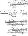
- FIGS. 9A-9D and FIGS. 10A-10C are cross-sectional side views of the variable-length bullnose assembly 802 of FIGS. 8A and 8B as used in exemplary operation, according to one or more embodiments. More particularly, FIGS. 9A-9D and 10A-10C are representative progressive views of the bullnose assembly 802 traversing the multilateral wellbore system 700 of FIG. 7 , where FIGS. 9A-9D depict the bullnose assembly 802 in its default configuration at the first junction 106a ( FIG. 7 ) and FIGS. 10A-10C depict the bullnose assembly 802 in its actuated configuration at the second junction 106b ( FIG. 7 ).
- FIGS. 9A-9D illustrated are progressive views of the bullnose assembly 802 in its default configuration interacting with and otherwise being deflected by the first deflector assembly 100a at the first junction 106a.
- the bullnose assembly 802 is shown engaging the upper deflector 110a after having been extended downhole within the main bore 104.
- the diameter 410c ( FIG. 8A ) of the bullnose tip 406 may be larger than the first width 302a ( FIG. 3A ) such that the bullnose tip 406 is unable to extend through the upper deflector 110a via the first channel 114a.
- the bullnose tip 406 may be configured to slidingly engage the ramped surface 112 until locating the second channel 114b.
- the bullnose assembly 802 may be able to extend through the upper deflector 110a via the second channel 114b. This is shown in FIG. 9B as the bullnose assembly 802 is advanced in the main bore 104 and otherwise extended at least partially through the upper deflector 110a.
- the bullnose assembly 802 is advanced further in the main bore 104 until the bullnose tip 406 and the sleeve member 804 exit the second channel 114b.
- the bullnose assembly 802 may no longer be supported within the second channel 114b and may instead fall into or otherwise be received by the first channel 114a. This is possible since the diameter 412c ( FIG. 9 ) of the body 404 of the bullnose assembly 802 is smaller than the first width 302a ( FIG. 3A ), and the length 814a ( FIG. 8A ) of the bullnose tip 406 in the default configuration is less than the distance 202 ( FIG.
- gravity may act on the bullnose assembly 802 and allow it to fall into the first channel 114a once the bullnose tip 406 and the sleeve member 804 exit the second channel 114b and thereby no longer support the bullnose assembly 802.
- the bullnose assembly 802 is advanced even further in the main bore 104 until the bullnose tip 406 enters or is otherwise received within the first conduit 116a.
- the first conduit 116a exhibits a diameter 304a ( FIG. 3B ) that is greater than the diameter 410c ( FIG. 8A ) of the bullnose tip 406 and can therefore guide the bullnose assembly 802 further down the main bore 104 past the first junction 106a ( FIG. 7 ) and otherwise not into the first lateral bore 108a.
- FIGS. 10A-10C depict the bullnose assembly 802 after having passed through the first junction 106a in the multilateral wellbore system 700 of FIG. 7 and is now advanced further within the main bore 104 until interacting with and otherwise being deflected by the second deflector assembly 100b arranged at the second junction 106b ( FIG. 7 ).
- the sleeve member 804 may be actuated, thereby moving the bullnose assembly 802 from its default configuration and into its actuated configuration as seen in FIGS. 10A-10C .
- the bullnose assembly 802 may be configured to span the distance 202 ( FIG. 2 ) between the upper and lower deflectors 110a,b and thereby enter the second lateral bore 108b.
- the bullnose assembly 802 is extended downhole in its actuated configuration within the main bore 104 and engages the upper deflector 110a of the second deflector assembly 100b.
- the diameter 410c ( FIG. 8A ) of the bullnose tip 406 may be larger than the first width 302a ( FIG. 3A ) such that the bullnose tip 406 is unable to extend through the upper deflector 110a via the first channel 114a. Instead, the bullnose tip 406 may be configured to slidingly engage the ramped surface 112 until locating the second channel 114b. Since the diameter 410c ( FIG. 8A ) of the bullnose tip 406 is smaller than the second width 302b ( FIG.
- the bullnose assembly 802 is able to extend through the upper deflector 110a via the second channel 114b. This is shown in FIG. 10B as the bullnose assembly 802 is advanced in the main bore 104 and otherwise extended at least partially through the upper deflector 110a.
- the bullnose assembly 802 is advanced further in the main bore 104 and directed into the second conduit 116b of the lower deflector 110b. This is possible since the combined length 814b ( FIG. 8B ) of the bullnose tip 406 and the sleeve member 804 is greater than the distance 202 ( FIG. 2 ) that separates the upper and lower deflectors 110a,b of the second deflector assembly 100b. In other words, since the distance 202 is less than the combined length 814b of the bullnose tip 406 and the sleeve member 804 in its actuated position, the bullnose assembly 802 is generally prevented from moving laterally within the main bore 104 and toward the first conduit 116a of the lower deflector 110b.
- the bullnose tip 406 is received by the second conduit 116b while at least a portion of the sleeve member 804 remains supported in the second channel 114b of the upper deflector 110a.
- the second conduit 116b exhibits a diameter 304b ( FIG. 3B ) that is greater than the diameter 410c ( FIG. 8A ) of the bullnose tip 406 and can therefore guide the bullnose assembly 802 toward the second lateral bore 108b.
- the sleeve member 804 may be actuated back to its default position. To accomplish this, in some embodiments, the hydraulic pressure within the bullnose assembly 802 may be released. In other embodiments, one or more actuating devices, as described above, may be configured to axially move the sleeve member 804 back to its default position.
- the bullnose assembly 802 may be pulled back up above the second junction 106b and then simply lowered back down in its default configuration and it will enter the main bore 104 below the second junction 106b. Again, this is possible since the combined length 814a ( FIG. 8A ) of the bullnose tip 406 and the sleeve member 804 in its default position is less than the distance 202 ( FIG. 2 ) that separates the upper and lower deflectors 110a,b of the second deflector assembly 100b. Accordingly, the bullnose assembly 802 may be received into the first channel 114a once the bullnose tip 406 and the sleeve member 804 exit the second channel 114b and no longer support the bullnose assembly 802 therein.
- the bullnose assembly 802 may be pulled back up above the first junction 106a, moved into its actuated configuration, and then lowered back downhole. In its actuated configuration, the bullnose assembly 802 may be advanced in the main bore 104 and will be directed into the second conduit 116b of the lower deflector 110b of the first deflector assembly 100a. Again, this is possible since the length 814b ( FIG. 8B ) of the bullnose tip 406 and the sleeve member 804 in its actuated position is greater than the distance 202 ( FIG. 2 ) that separates the upper and lower deflectors 110a,b.
- the bullnose tip 406 is received by the second conduit 116b while at least a portion of the sleeve member 804 remains supported in the second channel 114b, thereby directing the bullnose assembly 802 toward the first lateral bore 108a.
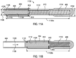
- FIGS. 11A and 11B With continued reference to FIGS. 1 and 2 , illustrated are cross-sectional side views of another exemplary bullnose assembly 1102 capable of adjusting its length, according to one or more embodiments.
- the bullnose assembly 1102 may be similar in some respects to the bullnose assemblies 402a,b and 802 of FIGS. 4A-B and 8A-B , respectively, and therefore will be best understood with reference thereto, where like numerals represent like elements not described again in detail.
- the bullnose assembly 1102 includes a body 404 and a bullnose tip 406 coupled to the distal end of the body 404 or otherwise forming an integral part thereof.
- the bullnose tip 406 of the bullnose assembly 1102 exhibits a seventh diameter 410d that may be the same as or different than the first, second, and fifth diameters 410a-c ( FIGS. 4A and 4B and FIG. 8A ).
- the seventh diameter 410c may be small enough and otherwise able to extend through the second width 302b ( FIG. 3A ) of the upper deflector 110a and the first and second diameters 304a,b ( FIG. 3B ) of the lower deflector 110b of the deflector assembly 100 ( FIGS. 1 and 2 ).
- the body 404 of the bullnose assembly 1102 exhibits an eighth diameter 412d that may be the same as or different from the third, fourth, and sixth diameters 412a-c ( FIGS. 4A and 4B and FIG. 8A ).
- the eighth diameter 412d may be smaller than the first, second, third, and fifth diameters 410a-d and also smaller than the first width 302a ( FIG. 3A ) of the upper deflector 110a of the deflector assembly 100 ( FIGS. 1 and 2 ), and otherwise able to be received therein.
- the bullnose assembly 1102 may further include the sleeve member 804, as generally described above with reference to FIGS. 8A and 8B .
- a piston 1104 may be movably arranged within a hydraulic cavity 1105 defined within the body 404.
- the piston 1104 may be operatively coupled to the sleeve member 804 such that movement of the piston 1104 correspondingly moves the sleeve member 804.
- one or more coupling pins 810 may operatively couple the piston 1104 to the sleeve member 804 and extend between the piston 1104 and the sleeve member 804 through the corresponding longitudinal grooves 812.
- the piston 1104 may be operatively coupled to the sleeve member 804 using other devices or coupling methods, such as magnets, as described above.
- FIG. 11A depicts the bullnose assembly 1102 in a default configuration
- FIG. 11B depicts the bullnose assembly 1102 in an actuated configuration
- the sleeve member 804 is arranged distally from the bullnose tip 406 such that the bullnose tip 406 effectively exhibits a first length 1106a that is greater than the distance 202 ( FIG. 2 ) between the upper and lower deflectors 110a,b of the deflector assembly 100 ( FIGS. 1 and 2 ).
- the sleeve member 804 is moved generally adjacent the bullnose tip 406 such that the bullnose tip 406 effectively exhibits a second length 1106b that incorporates the axial lengths of both the bullnose tip 406 and the sleeve member 804.
- the second length 1106b is less than the first length 1106a and also less than the distance 202 ( FIG. 2 ) between the upper and lower deflectors 110a,b of the deflector assembly 100.
- the sleeve member 804 may be actuated.
- actuating the sleeve member 804 involves applying hydraulic pressure to the bullnose assembly 1102. More particularly, a hydraulic fluid 1108 may be applied from a surface location, through the conveyance ( i.e. , coiled tubing, drill pipe, production tubing, etc.) coupled to the bullnose assembly 1102, and from the conveyance to the interior of the bullnose assembly 1102. At the bullnose assembly 1102, the hydraulic fluid 1108 enters the body 404 via the hydraulic cavity 1105 and acts on the end of the piston 1104.
- One or more sealing elements 1110 may be arranged between the piston 1104 and the inner surface of the hydraulic cavity 1105 such that sealed engagements at each location result.
- the hydraulic fluid 1108 acts on the piston 1104 such that it moves distally ( i.e ., to the right in FIGS. 11A and 11B ) within the hydraulic cavity 1105 and into a piston chamber 1112 defined within the bullnose tip 406.
- the hydraulic cavity 1105 and the piston chamber 1112 may be the same and the piston 1104 translates axially therein.
- the sleeve member 804 correspondingly moves axially since it is operatively coupled thereto.
- the coupling pins 810 translate axially within the longitudinal grooves 812 and thereby move the sleeve member 804 in the same direction.
- the piston 1104 engages a biasing device 1114 arranged within the piston chamber 1112 and compresses the biasing device 1114 such that a spring force is generated therein.
- the biasing device 1114 may be a helical spring, a series of Belleville washers, an air shock, or the like.
- the hydraulic pressure on the bullnose assembly 1102 may be released.
- the spring force built up in the biasing device 1114 may serve to force the piston 1104 (and therefore the sleeve member 804) back to the default position shown in FIG. 11A , and thereby effectively return the bullnose tip 406 to the first length 1106a.
- such an embodiment allows a well operator to decrease the overall length of the bullnose assembly 1102 on demand while downhole simply by applying pressure through the conveyance and to the bullnose assembly 1102.
- the present disclosure also contemplates using one or more actuating devices to physically adjust the axial position of the sleeve member 804 and thereby decrease the effective axial length 1106b of the bullnose tip 406.
- the actuating device (not shown) may be operatively coupled to the sleeve member 804 and configured to move the sleeve member 804 axially between the first length 1106a and the second length 1106b.
- the present disclosure further contemplates actuating the sleeve member 804 using fluid flow around the bullnose assembly 1102 or hydrostatic pressure, as generally described above.
- the sleeve member 804 may be configured to move axially with respect to the bullnose tip 406, and thereby effectively decrease the effective overall length of the bullnose tip 406.
- the sleeve member 804 would remain in the actuated position until it is desired to enter a lateral bore 108 ( FIGS. 1 and 2 ).
- the bullnose assembly 1102 would effectively exhibit the second length 1106b, and therefore be unable to enter a lateral bore 108 ( FIGS. 1 and 2 ) since the second length 1106b is shorter than the distance 202 ( FIGS. 1 and 2 ) between the upper and lower deflectors 110a,b of the deflector assembly 100.
- the bullnose assembly 1102 When it is desired to enter a lateral bore 108, the bullnose assembly 1102 may be returned to its default position, thereby providing the bullnose assembly 1102 with the first length 1106a. Since the first length 1106a is greater than the distance 202 ( FIGS. 1 and 2 ) between the upper and lower deflectors 110a,b of the deflector assembly 100, the bullnose tip 806 would be directed into the second conduit 116b of the lower deflector 110b and thereby guided into the lateral bore 108. As will be appreciated, similar to the bullnose assembly 802 of FIGS. 8A and 8B , the bullnose assembly 1102 may be used in the multilateral wellbore system 700 of FIG. 7 in order to access any of the lateral bores 108a-c by adjusting its axial length, as described above.
- the present disclosure also contemplates varying the length of the bullnose assemblies 802, 1102 generally described herein using a movable bullnose tip 406 instead of a movable sleeve member 804.
- the sleeve member 804 may be a stationary part or portion of the bullnose assembly 802, 1102 and instead the axial position of the bullnose tip 406 may be adjusted with respect to the sleeve member 804 in order to move between the default and actuated configurations described above.
- actuating the bullnose assembly 802 of FIGS. 8A and 8B would serve to move the bullnose tip 406 with respect to the sleeve member 804 from the first length 814a to the second length 814b.
- actuating the bullnose assembly 1102 of FIGS. 11A and 11B would serve to move the bullnose tip 406 with respect to the sleeve member 804 from the first length 1106a to the second length 1106b.
- actuating means may be employed in order to move the bullnose tip 406 with respect to the sleeve member 804.
- Such means include, but not are limited to, using hydraulic pressure acting on a piston operatively coupled to the bullnose tip 406, an actuating device operatively coupled to the bullnose tip 406, and a pressure drop created across the bullnose assembly 802, 1102 which forces a piston that is operatively coupled to the bullnose tip 406 to move.
- Each of embodiments A, B, and C may have one or more of the following additional elements in any combination: Element 1: wherein the upper deflector provides a ramped surface facing toward an uphole direction within the main bore, the ramped surface being configured to direct the bullnose assembly into the second channel. Element 2: wherein, when the length of the bullnose tip is greater than the predetermined distance, the bullnose assembly is directed into the second conduit and the lateral bore. Element 3: wherein, when the length of the bullnose tip is less than the predetermined distance, the bullnose assembly is directed into the first conduit and the lower portion of the main bore.
- Element 4 wherein the bullnose tip or the sleeve member is actuatable between a default configuration, where the length of the bullnose tip exhibits a first length, and an actuated configuration, where the length of the bullnose tip exhibits a second length.
- Element 5 wherein the first length is less than the predetermined distance, and the second length is greater than both the first length and the predetermined distance.
- Element 6 wherein the first length is greater than both the second length and the predetermined distance, and the second length is less than the predetermined distance.
- Element 7 wherein the bullnose tip or the sleeve member is actuatable using at least one of hydraulic pressure acting on a piston operatively coupled to one of the bullnose tip or the sleeve member, an actuating device operatively coupled to one of the bullnose tip or the sleeve member, and a pressure drop created across the bullnose assembly which forces a piston that is operatively coupled to one of the bullnose tip or the sleeve member to move.
- Element 8 wherein directing the bullnose assembly through the upper deflector includes engaging the bullnose tip on a ramped surface defined by the upper deflector, and directing the bullnose tip into and through the second channel with the ramped surface.
- Element 9 further comprising actuating the bullnose assembly between a default configuration, where the length of the bullnose tip exhibits a first length that is less than the predetermined distance, and an actuated configuration, where the length of the bullnose tip exhibits a second length that is greater than both the first length and the predetermined distance.
- Element 10 further comprising directing the bullnose assembly into the first conduit and the lower portion of the main bore when the length of the bullnose tip is the first length, and directing the bullnose assembly into the second conduit and the lateral bore when the length of the bullnose tip is the second length.
- Element 11 further comprising actuating the bullnose assembly between a default configuration, where the length of the bullnose tip exhibits a first length, and an actuated configuration, where the length of the bullnose tip exhibits a second length, wherein the second length is less than the predetermined distance and the first length is greater than both the second length and the predetermined distance.
- Element 12 further including directing the bullnose assembly into the second conduit and the lateral bore when the length of the bullnose tip is the first length, and directing the bullnose assembly into the first conduit and the lower portion of the main bore when the length of the bullnose tip is the second length.
- Element 13 further comprising actuating the bullnose assembly by using at least one of hydraulic pressure acting on a piston operatively coupled to one of the bullnose tip or the sleeve member, an actuating device operatively coupled to one of the bullnose tip or the sleeve member, and a pressure drop created across the bullnose assembly which forces a piston that is operatively coupled to one of the bullnose tip or the sleeve member to move.
- Element 14 wherein, when the length of the bullnose tip is the first length, the bullnose assembly is directed into the first conduit and the first lower portion of the main bore or the third conduit and the second lower portion of the main bore, and wherein when the length of the bullnose tip is the second length, the bullnose assembly is directed into the second conduit and the first lateral bore or the fourth conduit and the second lateral bore.
- Element 15 wherein, when the length of the bullnose tip is the first length, the bullnose assembly is directed into the second conduit and the first lateral bore or the fourth conduit and the second lateral bore, and wherein, when the length of the bullnose tip is the second length, the bullnose assembly is directed into the first conduit and the first lower portion of the main bore or the third conduit and the second lower portion of the main bore.
- compositions and methods are described in terms of “comprising,” “containing,” or “including” various components or steps, the compositions and methods can also “consist essentially of” or “consist of” the various components and steps. All numbers and ranges disclosed above may vary by some amount. Whenever a numerical range with a lower limit and an upper limit is disclosed, any number and any included range falling within the range is specifically disclosed. In particular, every range of values (of the form, “from about a to about b,” or, equivalently, “from approximately a to b,” or, equivalently, “from approximately a-b”) disclosed herein is to be understood to set forth every number and range encompassed within the broader range of values.
Landscapes
- Engineering & Computer Science (AREA)
- Geology (AREA)
- Life Sciences & Earth Sciences (AREA)
- Mining & Mineral Resources (AREA)
- Geochemistry & Mineralogy (AREA)
- Fluid Mechanics (AREA)
- Environmental & Geological Engineering (AREA)
- General Life Sciences & Earth Sciences (AREA)
- Physics & Mathematics (AREA)
- Mechanical Engineering (AREA)
- Earth Drilling (AREA)
- Operation Control Of Excavators (AREA)
- Drilling And Boring (AREA)
- Processing Of Stones Or Stones Resemblance Materials (AREA)
- Portable Nailing Machines And Staplers (AREA)
- Air-Flow Control Members (AREA)
- Media Introduction/Drainage Providing Device (AREA)
Claims (15)
- Bohrlochsystem, umfassend:eine erste Lenkblechbaugruppe, umfassend:ein erstes oberes Lenkblech (110a), das innerhalb einer Hauptbohrung (104) eines Bohrlochs angeordnet ist und das erste und zweite miteinander verbundene Kanäle (114a, b) definiert, die sich längs durch das obere Lenkblech erstrecken; undein erstes unteres Lenkblech (110b), das innerhalb der Hauptbohrung angeordnet ist und von dem oberen Lenkblech um eine vorbestimmte Distanz beabstandet ist, wobei das untere Lenkblech ein erstes Leitungsrohr (116a) definiert, das mit einem ersten unteren Teil der Hauptbohrung kommuniziert, und ein zweites Leitungsrohr (116b), das mit einer ersten lateralen Bohrung (108) kommuniziert; undeine Rundkantenbaugruppe (402a, 402b), einschließlich eines Körpers (404), einer Rundkantenspitze (406), die an einem distalen Ende des Körpers angeordnet ist, und eines Muffenelements (804), das um den Körper herum angeordnet ist, wobei eines von der Rundkantenspitze und dem Muffenelement axial beweglich ist, um eine Länge (408a, 408b) der Rundkantenspitze zu variieren,wobei die oberen und unteren Lenkbleche derart konfiguriert sind, um die Rundkantenbaugruppe entweder in die laterale Bohrung oder den unteren Teil der Hauptbohrung, basierend auf der Länge der Rundkantenspitze im Vergleich zu der vorbestimmten Distanz, zu leiten.
- Bohrlochsystem nach Anspruch 1, wobei das obere Lenkblech eine angeschrägte Fläche (112) bereitstellt, die in einer Lochaufwärtsrichtung innerhalb der Hauptbohrung gerichtet ist, wobei die angeschrägte Fläche derart konfiguriert ist, um die Rundkantenbaugruppe in den zweiten Kanal zu leiten.
- Bohrlochsystem nach Anspruch 1 oder 2, wobei, wenn die Länge der Rundkantenspitze länger ist als die vorbestimmte Distanz, die Rundkantenbaugruppe in das zweite Leitungsrohr und die laterale Bohrung geleitet wird.
- Bohrlochsystem nach Anspruch 1 oder 2, wobei, wenn die Länge der Rundkantenspitze kürzer ist als die vorbestimmte Distanz, die Rundkantenbaugruppe in das erste Leitungsrohr und den unteren Teil der Hauptbohrung geleitet wird.
- Bohrlochsystem nach Anspruch 1, 2, 3 oder 4, wobei die Rundkantenspitze oder das Muffenelement zwischen einer Vorgabekonfiguration, in der die Länge der Rundkantenspitze eine erste Länge vorweist, und einer betätigten Konfiguration betätigbar ist, in der die Länge der Rundkantenspitze eine zweite Länge vorweist.
- Bohrlochsystem nach Anspruch 5, wobei die erste Länge kürzer ist als die vorbestimmte Distanz, und die zweite Länge länger ist als beide, die erste Länge und die vorbestimmte Distanz, oder
wobei die erste Länge länger ist als beide, die zweite Länge und die vorbestimmte Distanz, und die zweite Länge kürzer ist als die vorbestimmte Distanz. - Bohrlochsystem nach einem der vorstehenden Ansprüche, wobei die Rundkantenspitze oder das Muffenelement unter Verwendung von wenigstens einem eines Hydraulikdrucks, der auf einen Kolben einwirkt, der operativ an eines von der Rundkantenspitze oder vom Muffenelement gekoppelt ist, einer Betätigungsvorrichtung, die operativ an eines von der Rundkantenspitze oder vom Muffenelement gekoppelt ist, und eines Druckabfalls, der durch die Rundkantenbaugruppe hindurch erzeugt wird, welcher einen Kolben drängt, der operativ an eines von der Rundkantenspitze oder vom Muffenelement zum Bewegen gekoppelt ist, betätigbar ist.
- Verfahren, umfassend:das Einführen einer Rundkantenbaugruppe (402a, 402b) in eine Hauptbohrung (104) eines Bohrlochs, wobei die Rundkantenbaugruppe einen Körper (404), eine Rundkantenspitze (406), die an einem distalen Ende des Körpers angeordnet ist, und ein Muffenelement (804), das um den Körper herum angeordnet ist, einschließt, wobei wenigstens eines von der Rundkantenspitze und dem Muffenelement axial beweglich ist, um eine Länge (408a, 408b) der Rundkantenspitze zu variieren;das Leiten der Rundkantenbaugruppe durch ein oberes Lenkblech (110a), das innerhalb der Hauptbohrung angeordnet ist, wobei das obere Lenkblech erste und zweite miteinander verbundene Kanäle (114a, b) definiert, die sich längs durch dieses hindurch erstrecken;das Vorwärtsbewegen der Rundkantenbaugruppe zu einem unteren Lenkblech (110b), das innerhalb der Hauptbohrung angeordnet und von dem oberen Lenkblech um eine vorbestimmte Distanz beabstandet ist, wobei das untere Lenkblech ein erstes Leitungsrohr (116a), das mit einem unteren Teil der Hauptbohrung kommuniziert, und ein zweites Leitungsrohr (116b), das mit einer lateralen Bohrung (108) kommuniziert, definiert; unddas Leiten der Rundkantenbaugruppe entweder in die laterale Bohrung oder den unteren Teil der Hauptbohrung, basierend auf der Länge der Rundkantenspitze im Vergleich zu der vorbestimmten Distanz.
- Verfahren nach Anspruch 8, wobei das Leiten der Rundkantenbaugruppe durch das obere Lenkblech Folgendes umfasst:das Eingreifen der Rundkantenspitze an einer angeschrägten Fläche (112), die durch das obere Lenkblech definiert ist; unddas Leiten der Rundkantensitze in und durch den zweiten Kanal mit der angeschrägten Fläche.
- Verfahren nach Anspruch 8 oder 9, weiter umfassend das Betätigen der Rundkantenbaugruppe zwischen einer Vorgabekonfiguration, in der die Länge der Rundkantenspitze eine erste Länge vorweist, die kürzer als die vorbestimmte Distanz ist, und einer betätigten Konfiguration, in der die Länge der Rundkantenspitze eine zweite Länge vorweist, die länger als beide, die erste Länge und die vorbestimmte Distanz ist, optional
weiter umfassend:das Leiten der Rundkantenbaugruppe in das erste Leitungsrohr und den unteren Teil der Hauptbohrung, wenn die Länge der Rundkantenspitze die erste Länge ist; unddas Leiten der Rundkantenbaugruppe in das zweite Leitungsrohr und die laterale Bohrung, wenn die Länge der Rundkantenspitze die zweite Länge ist. - Verfahren nach Anspruch 8, 9 oder 10, weiter umfassend das Betätigen der Rundkantenbaugruppe zwischen einer Vorgabekonfiguration, in der die Länge der Rundkantenspitze eine erste Länge vorweist, und einer betätigten Konfiguration, in der die Länge der Rundkantenspitze eine zweite Länge vorweist, wobei die zweite Länge kürzer ist als die vorbestimmte Distanz, und die erste Länge länger ist als beide, die zweite Länge und die vorbestimmte Distanz, optional
weiter umfassend:das Leiten der Rundkantenbaugruppe in das zweite Leitungsrohr und die laterale Bohrung, wenn die Länge der Rundkantenspitze die erste Länge ist; unddas Leiten der Rundkantenbaugruppe in das erste Leitungsrohr und den unteren Teil der Hauptbohrung, wenn die Länge der Rundkantenspitze die zweite Länge ist. - Verfahren nach einem der Ansprüche 8 bis 11, weiter umfassend das Betätigen der Rundkantenbaugruppe unter Verwendung von wenigstens einem eines Hydraulikdrucks, der auf einen Kolben (806) einwirkt, der operativ an eines von der Rundkantenspitze oder dem Muffenelement gekoppelt ist, einer Betätigungsvorrichtung, die operativ an eines von der Rundkantenspitze oder dem Muffenelement gekoppelt ist, und eines Druckabfalls, der durch die Rundkantenbaugruppe hindurch erzeugt wird, welcher einen Kolben drängt, der operativ an eines von der Rundkantenspitze oder dem Muffenelement zum Bewegen gekoppelt ist.
- Multilaterales Bohrlochsystem, umfassend:eine Hauptbohrung, die einen ersten Übergang aufweist, und einen zweiten Übergang, der lochabwärts von dem ersten Übergang beabstandet ist;das Bohrlochsystem nach einem der Ansprüche 1 bis 7, wobei die erste Lenkblechbaugruppe an dem ersten Übergang angeordnet ist;eine zweite Lenkblechbaugruppe, die an dem zweiten Übergang angeordnet ist und ein zweites oberes Lenkblech umfasst, und ein zweites unteres Lenkblech, das von dem zweiten oberen Lenkblech um eine vorbestimmte Distanz beabstandet ist, wobei das zweite untere Lenkblech ein drittes Leitungsrohr definiert, das mit einem zweiten unteren Teil der Hauptbohrung kommuniziert, und ein viertes Leitungsrohr, das mit einer zweiten lateralen Bohrung kommuniziert;wobei die ersten und zweiten Lenkblechbaugruppen derart konfiguriert sind, um die Rundkantenbaugruppe entweder in die ersten und zweiten lateralen Bohrungen oder die ersten und zweiten unteren Teile der Hauptbohrungen, basierend auf der Länge der Rundkantenspitze im Vergleich zu der vorbestimmten Distanz, zu leiten.
- Multilaterales Bohrlochsystem nach Anspruch 13, wobei, wenn die Länge der Rundkantenspitze die erste Länge ist, die Rundkantenbaugruppe in das erste Leitungsrohr und den ersten unteren Teil der Hauptbohrung, oder das dritte Leitungsrohr und den zweiten unteren Teil der Hauptbohrung geleitet wird, und wobei
wenn die Länge der Rundkantenspitze die zweite Länge ist, die Rundkantenbaugruppe in das zweite Leitungsrohr und die erste laterale Bohrung, oder das vierte Leitungsrohr und die zweite laterale Bohrung geleitet wird. - Multilaterales Bohrlochsystem nach Anspruch 13 oder 14, wobei,
wenn die Länge der Rundkantenspitze die erste Länge ist, die Rundkantenbaugruppe in das zweite Leitungsrohr und die erste laterale Bohrung, oder das vierte Leitungsrohr und die zweite laterale Bohrung geleitet wird; und wobei,
wenn die Länge der Rundkantenspitze die zweite Länge ist, die Rundkantenbaugruppe in das erste Leitungsrohr und den ersten unteren Teil der Hauptbohrung, oder das dritte Leitungsrohr und den zweiten unteren Teil der Hauptbohrung geleitet wird.
Applications Claiming Priority (1)
| Application Number | Priority Date | Filing Date | Title |
|---|---|---|---|
| PCT/US2013/052080 WO2015012844A1 (en) | 2013-07-25 | 2013-07-25 | Adjustable bullnose assembly for use with a wellbore deflector assembly |
Publications (3)
| Publication Number | Publication Date |
|---|---|
| EP2994595A1 EP2994595A1 (de) | 2016-03-16 |
| EP2994595A4 EP2994595A4 (de) | 2017-01-18 |
| EP2994595B1 true EP2994595B1 (de) | 2018-06-06 |
Family
ID=52393700
Family Applications (1)
| Application Number | Title | Priority Date | Filing Date |
|---|---|---|---|
| EP13890229.1A Active EP2994595B1 (de) | 2013-07-25 | 2013-07-25 | Expandierbare abgerundete anordnung zur verwendung mit einer bohrlochdeflektoranordnung |
Country Status (11)
| Country | Link |
|---|---|
| US (1) | US9140082B2 (de) |
| EP (1) | EP2994595B1 (de) |
| CN (1) | CN105324549B (de) |
| AR (1) | AR097808A1 (de) |
| AU (1) | AU2013394891B2 (de) |
| BR (1) | BR112015032614B1 (de) |
| CA (1) | CA2914910C (de) |
| MX (1) | MX373172B (de) |
| RU (1) | RU2627058C1 (de) |
| SG (1) | SG11201510102VA (de) |
| WO (1) | WO2015012844A1 (de) |
Families Citing this family (8)
| Publication number | Priority date | Publication date | Assignee | Title |
|---|---|---|---|---|
| EP2989279B1 (de) * | 2013-07-25 | 2018-07-18 | Halliburton Energy Services, Inc. | Ablenkungsvorrichtung für ein seitliches bohrloch |
| BR112015032981B1 (pt) * | 2013-07-25 | 2021-11-16 | Halliburton Energy Services, Inc | Montagem de bullnose de comprimento variável e expansível para uso com uma montagem de defletor de furo de poço |
| EP2994595B1 (de) | 2013-07-25 | 2018-06-06 | Halliburton Energy Services, Inc. | Expandierbare abgerundete anordnung zur verwendung mit einer bohrlochdeflektoranordnung |
| AU2013399088B2 (en) | 2013-08-31 | 2016-11-17 | Halliburton Energy Services, Inc. | Deflector assembly for a lateral wellbore |
| WO2017160278A1 (en) * | 2016-03-15 | 2017-09-21 | Halliburton Energy Services, Inc. | Dual bore co-mingler with multiple position inner sleeve |
| WO2020097196A1 (en) | 2018-11-09 | 2020-05-14 | Halliburton Energy Services, Inc. | Multilateral multistage system and method |
| NO20220575A1 (en) | 2019-12-10 | 2022-05-12 | Halliburton Energy Services Inc | A method for high-pressure access through a multilateral junction |
| GB2615356B (en) * | 2022-02-07 | 2024-03-27 | Enovate Systems Ltd | Bore selector |
Family Cites Families (18)
| Publication number | Priority date | Publication date | Assignee | Title |
|---|---|---|---|---|
| US3866628A (en) * | 1973-06-14 | 1975-02-18 | Exxon Production Research Co | Detent diverter |
| US4570673A (en) * | 1984-10-01 | 1986-02-18 | Halliburton Company | Fluid flow delivery system |
| SU1798466A1 (ru) * | 1989-12-15 | 1993-02-28 | Inst Burovoi Tekhnik | Cпocoб ctpoиteльctba mhoгoctboльhoй ckbaжиhы |
| US5353876A (en) * | 1992-08-07 | 1994-10-11 | Baker Hughes Incorporated | Method and apparatus for sealing the juncture between a verticle well and one or more horizontal wells using mandrel means |
| US5458199A (en) * | 1992-08-28 | 1995-10-17 | Marathon Oil Company | Assembly and process for drilling and completing multiple wells |
| US5526880A (en) * | 1994-09-15 | 1996-06-18 | Baker Hughes Incorporated | Method for multi-lateral completion and cementing the juncture with lateral wellbores |
| US5685373A (en) * | 1995-07-26 | 1997-11-11 | Marathon Oil Company | Assembly and process for drilling and completing multiple wells |
| CA2198689C (en) * | 1996-03-11 | 2006-05-02 | Herve Ohmer | Method and apparatus for establishing branch wells at a node of a parent well |
| CA2218278C (en) * | 1997-10-10 | 2001-10-09 | Baroid Technology,Inc | Apparatus and method for lateral wellbore completion |
| BR0009829B1 (pt) * | 1999-04-19 | 2009-08-11 | equipamento para poço em profundidade para uso em uma tubulação de revestimento de poço, e processo para acabamento de um poço. | |
| US6527067B1 (en) * | 1999-08-04 | 2003-03-04 | Bj Services Company | Lateral entry guidance system (LEGS) |
| US6789628B2 (en) * | 2002-06-04 | 2004-09-14 | Halliburton Energy Services, Inc. | Systems and methods for controlling flow and access in multilateral completions |
| GB2396168B (en) | 2002-12-02 | 2006-01-25 | Smith International | Downhole deflector member and method of using same |
| US7299878B2 (en) | 2003-09-24 | 2007-11-27 | Halliburton Energy Services, Inc. | High pressure multiple branch wellbore junction |
| US8479844B2 (en) * | 2007-03-22 | 2013-07-09 | Shell Oil Company | Distance holder with jet deflector |
| US8967277B2 (en) * | 2011-06-03 | 2015-03-03 | Halliburton Energy Services, Inc. | Variably configurable wellbore junction assembly |
| US8701775B2 (en) | 2011-06-03 | 2014-04-22 | Halliburton Energy Services, Inc. | Completion of lateral bore with high pressure multibore junction assembly |
| EP2994595B1 (de) | 2013-07-25 | 2018-06-06 | Halliburton Energy Services, Inc. | Expandierbare abgerundete anordnung zur verwendung mit einer bohrlochdeflektoranordnung |
-
2013
- 2013-07-25 EP EP13890229.1A patent/EP2994595B1/de active Active
- 2013-07-25 RU RU2015156474A patent/RU2627058C1/ru active
- 2013-07-25 CA CA2914910A patent/CA2914910C/en active Active
- 2013-07-25 SG SG11201510102VA patent/SG11201510102VA/en unknown
- 2013-07-25 BR BR112015032614-5A patent/BR112015032614B1/pt active IP Right Grant
- 2013-07-25 MX MX2016000068A patent/MX373172B/es active IP Right Grant
- 2013-07-25 AU AU2013394891A patent/AU2013394891B2/en active Active
- 2013-07-25 WO PCT/US2013/052080 patent/WO2015012844A1/en not_active Ceased
- 2013-07-25 CN CN201380077676.4A patent/CN105324549B/zh not_active Expired - Fee Related
- 2013-07-25 US US14/358,900 patent/US9140082B2/en active Active
-
2014
- 2014-07-04 AR ARP140102504A patent/AR097808A1/es active IP Right Grant
Non-Patent Citations (1)
| Title |
|---|
| None * |
Also Published As
| Publication number | Publication date |
|---|---|
| SG11201510102VA (en) | 2016-01-28 |
| BR112015032614B1 (pt) | 2021-08-24 |
| CN105324549A (zh) | 2016-02-10 |
| MX373172B (es) | 2020-04-22 |
| AR097808A1 (es) | 2016-04-20 |
| US20150184474A1 (en) | 2015-07-02 |
| EP2994595A1 (de) | 2016-03-16 |
| BR112015032614A2 (pt) | 2017-07-25 |
| RU2627058C1 (ru) | 2017-08-03 |
| WO2015012844A1 (en) | 2015-01-29 |
| CA2914910C (en) | 2018-01-16 |
| MX2016000068A (es) | 2016-06-15 |
| CA2914910A1 (en) | 2015-01-29 |
| EP2994595A4 (de) | 2017-01-18 |
| AU2013394891A1 (en) | 2015-12-24 |
| AU2013394891B2 (en) | 2016-05-26 |
| US9140082B2 (en) | 2015-09-22 |
| CN105324549B (zh) | 2017-06-13 |
Similar Documents
| Publication | Publication Date | Title |
|---|---|---|
| EP2994595B1 (de) | Expandierbare abgerundete anordnung zur verwendung mit einer bohrlochdeflektoranordnung | |
| US9260945B2 (en) | Expandable and variable-length bullnose assembly for use with a wellbore deflector assembly | |
| US8985203B2 (en) | Expandable bullnose assembly for use with a wellbore deflector | |
| AU2013407299B2 (en) | Variable diameter bullnose assembly | |
| AU2016208447B2 (en) | Expandable bullnose assembly for use with a wellbore deflector | |
| EP3272991B1 (de) | Expandierbare abgerundete anordnung zur verwendung mit einem bohrlochdeflektor |
Legal Events
| Date | Code | Title | Description |
|---|---|---|---|
| PUAI | Public reference made under article 153(3) epc to a published international application that has entered the european phase |
Free format text: ORIGINAL CODE: 0009012 |
|
| 17P | Request for examination filed |
Effective date: 20151210 |
|
| AK | Designated contracting states |
Kind code of ref document: A1 Designated state(s): AL AT BE BG CH CY CZ DE DK EE ES FI FR GB GR HR HU IE IS IT LI LT LU LV MC MK MT NL NO PL PT RO RS SE SI SK SM TR |
|
| AX | Request for extension of the european patent |
Extension state: BA ME |
|
| DAX | Request for extension of the european patent (deleted) | ||
| A4 | Supplementary search report drawn up and despatched |
Effective date: 20161219 |
|
| RIC1 | Information provided on ipc code assigned before grant |
Ipc: E21B 41/00 20060101ALI20161213BHEP Ipc: E21B 7/06 20060101AFI20161213BHEP Ipc: E21B 19/24 20060101ALI20161213BHEP Ipc: E21B 15/04 20060101ALI20161213BHEP |
|
| GRAP | Despatch of communication of intention to grant a patent |
Free format text: ORIGINAL CODE: EPIDOSNIGR1 |
|
| RIC1 | Information provided on ipc code assigned before grant |
Ipc: E21B 7/06 20060101AFI20180126BHEP Ipc: E21B 23/12 20060101ALI20180126BHEP Ipc: E21B 41/00 20060101ALI20180126BHEP Ipc: E21B 19/24 20060101ALI20180126BHEP Ipc: E21B 15/04 20060101ALI20180126BHEP |
|
| INTG | Intention to grant announced |
Effective date: 20180226 |
|
| GRAS | Grant fee paid |
Free format text: ORIGINAL CODE: EPIDOSNIGR3 |
|
| GRAA | (expected) grant |
Free format text: ORIGINAL CODE: 0009210 |
|
| AK | Designated contracting states |
Kind code of ref document: B1 Designated state(s): AL AT BE BG CH CY CZ DE DK EE ES FI FR GB GR HR HU IE IS IT LI LT LU LV MC MK MT NL NO PL PT RO RS SE SI SK SM TR |
|
| REG | Reference to a national code |
Ref country code: GB Ref legal event code: FG4D |
|
| REG | Reference to a national code |
Ref country code: CH Ref legal event code: EP Ref country code: AT Ref legal event code: REF Ref document number: 1006292 Country of ref document: AT Kind code of ref document: T Effective date: 20180615 |
|
| REG | Reference to a national code |
Ref country code: IE Ref legal event code: FG4D |
|
| REG | Reference to a national code |
Ref country code: DE Ref legal event code: R096 Ref document number: 602013038734 Country of ref document: DE |
|
| REG | Reference to a national code |
Ref country code: NO Ref legal event code: T2 Effective date: 20180606 |
|
| REG | Reference to a national code |
Ref country code: NL Ref legal event code: MP Effective date: 20180606 |
|
| REG | Reference to a national code |
Ref country code: LT Ref legal event code: MG4D |
|
| PG25 | Lapsed in a contracting state [announced via postgrant information from national office to epo] |
Ref country code: ES Free format text: LAPSE BECAUSE OF FAILURE TO SUBMIT A TRANSLATION OF THE DESCRIPTION OR TO PAY THE FEE WITHIN THE PRESCRIBED TIME-LIMIT Effective date: 20180606 Ref country code: BG Free format text: LAPSE BECAUSE OF FAILURE TO SUBMIT A TRANSLATION OF THE DESCRIPTION OR TO PAY THE FEE WITHIN THE PRESCRIBED TIME-LIMIT Effective date: 20180906 Ref country code: CY Free format text: LAPSE BECAUSE OF FAILURE TO SUBMIT A TRANSLATION OF THE DESCRIPTION OR TO PAY THE FEE WITHIN THE PRESCRIBED TIME-LIMIT Effective date: 20180606 Ref country code: LT Free format text: LAPSE BECAUSE OF FAILURE TO SUBMIT A TRANSLATION OF THE DESCRIPTION OR TO PAY THE FEE WITHIN THE PRESCRIBED TIME-LIMIT Effective date: 20180606 Ref country code: FI Free format text: LAPSE BECAUSE OF FAILURE TO SUBMIT A TRANSLATION OF THE DESCRIPTION OR TO PAY THE FEE WITHIN THE PRESCRIBED TIME-LIMIT Effective date: 20180606 Ref country code: SE Free format text: LAPSE BECAUSE OF FAILURE TO SUBMIT A TRANSLATION OF THE DESCRIPTION OR TO PAY THE FEE WITHIN THE PRESCRIBED TIME-LIMIT Effective date: 20180606 |
|
| PG25 | Lapsed in a contracting state [announced via postgrant information from national office to epo] |
Ref country code: HR Free format text: LAPSE BECAUSE OF FAILURE TO SUBMIT A TRANSLATION OF THE DESCRIPTION OR TO PAY THE FEE WITHIN THE PRESCRIBED TIME-LIMIT Effective date: 20180606 Ref country code: RS Free format text: LAPSE BECAUSE OF FAILURE TO SUBMIT A TRANSLATION OF THE DESCRIPTION OR TO PAY THE FEE WITHIN THE PRESCRIBED TIME-LIMIT Effective date: 20180606 Ref country code: GR Free format text: LAPSE BECAUSE OF FAILURE TO SUBMIT A TRANSLATION OF THE DESCRIPTION OR TO PAY THE FEE WITHIN THE PRESCRIBED TIME-LIMIT Effective date: 20180907 Ref country code: LV Free format text: LAPSE BECAUSE OF FAILURE TO SUBMIT A TRANSLATION OF THE DESCRIPTION OR TO PAY THE FEE WITHIN THE PRESCRIBED TIME-LIMIT Effective date: 20180606 |
|
| REG | Reference to a national code |
Ref country code: AT Ref legal event code: MK05 Ref document number: 1006292 Country of ref document: AT Kind code of ref document: T Effective date: 20180606 |
|
| PG25 | Lapsed in a contracting state [announced via postgrant information from national office to epo] |
Ref country code: NL Free format text: LAPSE BECAUSE OF FAILURE TO SUBMIT A TRANSLATION OF THE DESCRIPTION OR TO PAY THE FEE WITHIN THE PRESCRIBED TIME-LIMIT Effective date: 20180606 |
|
| PG25 | Lapsed in a contracting state [announced via postgrant information from national office to epo] |
Ref country code: SK Free format text: LAPSE BECAUSE OF FAILURE TO SUBMIT A TRANSLATION OF THE DESCRIPTION OR TO PAY THE FEE WITHIN THE PRESCRIBED TIME-LIMIT Effective date: 20180606 Ref country code: CZ Free format text: LAPSE BECAUSE OF FAILURE TO SUBMIT A TRANSLATION OF THE DESCRIPTION OR TO PAY THE FEE WITHIN THE PRESCRIBED TIME-LIMIT Effective date: 20180606 Ref country code: RO Free format text: LAPSE BECAUSE OF FAILURE TO SUBMIT A TRANSLATION OF THE DESCRIPTION OR TO PAY THE FEE WITHIN THE PRESCRIBED TIME-LIMIT Effective date: 20180606 Ref country code: PL Free format text: LAPSE BECAUSE OF FAILURE TO SUBMIT A TRANSLATION OF THE DESCRIPTION OR TO PAY THE FEE WITHIN THE PRESCRIBED TIME-LIMIT Effective date: 20180606 Ref country code: EE Free format text: LAPSE BECAUSE OF FAILURE TO SUBMIT A TRANSLATION OF THE DESCRIPTION OR TO PAY THE FEE WITHIN THE PRESCRIBED TIME-LIMIT Effective date: 20180606 Ref country code: IS Free format text: LAPSE BECAUSE OF FAILURE TO SUBMIT A TRANSLATION OF THE DESCRIPTION OR TO PAY THE FEE WITHIN THE PRESCRIBED TIME-LIMIT Effective date: 20181006 Ref country code: AT Free format text: LAPSE BECAUSE OF FAILURE TO SUBMIT A TRANSLATION OF THE DESCRIPTION OR TO PAY THE FEE WITHIN THE PRESCRIBED TIME-LIMIT Effective date: 20180606 |
|
| REG | Reference to a national code |
Ref country code: DE Ref legal event code: R119 Ref document number: 602013038734 Country of ref document: DE |
|
| PG25 | Lapsed in a contracting state [announced via postgrant information from national office to epo] |
Ref country code: IT Free format text: LAPSE BECAUSE OF FAILURE TO SUBMIT A TRANSLATION OF THE DESCRIPTION OR TO PAY THE FEE WITHIN THE PRESCRIBED TIME-LIMIT Effective date: 20180606 Ref country code: SM Free format text: LAPSE BECAUSE OF FAILURE TO SUBMIT A TRANSLATION OF THE DESCRIPTION OR TO PAY THE FEE WITHIN THE PRESCRIBED TIME-LIMIT Effective date: 20180606 |
|
| REG | Reference to a national code |
Ref country code: CH Ref legal event code: PL |
|
| PG25 | Lapsed in a contracting state [announced via postgrant information from national office to epo] |
Ref country code: LU Free format text: LAPSE BECAUSE OF NON-PAYMENT OF DUE FEES Effective date: 20180725 Ref country code: MC Free format text: LAPSE BECAUSE OF FAILURE TO SUBMIT A TRANSLATION OF THE DESCRIPTION OR TO PAY THE FEE WITHIN THE PRESCRIBED TIME-LIMIT Effective date: 20180606 |
|
| REG | Reference to a national code |
Ref country code: BE Ref legal event code: MM Effective date: 20180731 |
|
| PLBE | No opposition filed within time limit |
Free format text: ORIGINAL CODE: 0009261 |
|
| STAA | Information on the status of an ep patent application or granted ep patent |
Free format text: STATUS: NO OPPOSITION FILED WITHIN TIME LIMIT |
|
| REG | Reference to a national code |
Ref country code: IE Ref legal event code: MM4A |
|
| PG25 | Lapsed in a contracting state [announced via postgrant information from national office to epo] |
Ref country code: CH Free format text: LAPSE BECAUSE OF NON-PAYMENT OF DUE FEES Effective date: 20180731 Ref country code: LI Free format text: LAPSE BECAUSE OF NON-PAYMENT OF DUE FEES Effective date: 20180731 Ref country code: IE Free format text: LAPSE BECAUSE OF NON-PAYMENT OF DUE FEES Effective date: 20180725 Ref country code: DE Free format text: LAPSE BECAUSE OF NON-PAYMENT OF DUE FEES Effective date: 20190201 |
|
| 26N | No opposition filed |
Effective date: 20190307 |
|
| GBPC | Gb: european patent ceased through non-payment of renewal fee |
Effective date: 20180906 |
|
| PG25 | Lapsed in a contracting state [announced via postgrant information from national office to epo] |
Ref country code: DK Free format text: LAPSE BECAUSE OF FAILURE TO SUBMIT A TRANSLATION OF THE DESCRIPTION OR TO PAY THE FEE WITHIN THE PRESCRIBED TIME-LIMIT Effective date: 20180606 Ref country code: BE Free format text: LAPSE BECAUSE OF NON-PAYMENT OF DUE FEES Effective date: 20180731 Ref country code: SI Free format text: LAPSE BECAUSE OF FAILURE TO SUBMIT A TRANSLATION OF THE DESCRIPTION OR TO PAY THE FEE WITHIN THE PRESCRIBED TIME-LIMIT Effective date: 20180606 |
|
| PG25 | Lapsed in a contracting state [announced via postgrant information from national office to epo] |
Ref country code: FR Free format text: LAPSE BECAUSE OF NON-PAYMENT OF DUE FEES Effective date: 20180806 |
|
| PG25 | Lapsed in a contracting state [announced via postgrant information from national office to epo] |
Ref country code: GB Free format text: LAPSE BECAUSE OF NON-PAYMENT OF DUE FEES Effective date: 20180906 |
|
| PG25 | Lapsed in a contracting state [announced via postgrant information from national office to epo] |
Ref country code: AL Free format text: LAPSE BECAUSE OF FAILURE TO SUBMIT A TRANSLATION OF THE DESCRIPTION OR TO PAY THE FEE WITHIN THE PRESCRIBED TIME-LIMIT Effective date: 20180606 |
|
| PG25 | Lapsed in a contracting state [announced via postgrant information from national office to epo] |
Ref country code: MT Free format text: LAPSE BECAUSE OF NON-PAYMENT OF DUE FEES Effective date: 20180725 |
|
| PG25 | Lapsed in a contracting state [announced via postgrant information from national office to epo] |
Ref country code: TR Free format text: LAPSE BECAUSE OF FAILURE TO SUBMIT A TRANSLATION OF THE DESCRIPTION OR TO PAY THE FEE WITHIN THE PRESCRIBED TIME-LIMIT Effective date: 20180606 |
|
| PG25 | Lapsed in a contracting state [announced via postgrant information from national office to epo] |
Ref country code: PT Free format text: LAPSE BECAUSE OF FAILURE TO SUBMIT A TRANSLATION OF THE DESCRIPTION OR TO PAY THE FEE WITHIN THE PRESCRIBED TIME-LIMIT Effective date: 20180606 |
|
| PG25 | Lapsed in a contracting state [announced via postgrant information from national office to epo] |
Ref country code: HU Free format text: LAPSE BECAUSE OF FAILURE TO SUBMIT A TRANSLATION OF THE DESCRIPTION OR TO PAY THE FEE WITHIN THE PRESCRIBED TIME-LIMIT; INVALID AB INITIO Effective date: 20130725 Ref country code: MK Free format text: LAPSE BECAUSE OF NON-PAYMENT OF DUE FEES Effective date: 20180606 |
|
| PGFP | Annual fee paid to national office [announced via postgrant information from national office to epo] |
Ref country code: NO Payment date: 20250623 Year of fee payment: 13 |