EP2994415B1 - A process for producing ammonia synthesis gas with high temperature shift and low steam-to-carbon ratio - Google Patents
A process for producing ammonia synthesis gas with high temperature shift and low steam-to-carbon ratio Download PDFInfo
- Publication number
- EP2994415B1 EP2994415B1 EP14721380.5A EP14721380A EP2994415B1 EP 2994415 B1 EP2994415 B1 EP 2994415B1 EP 14721380 A EP14721380 A EP 14721380A EP 2994415 B1 EP2994415 B1 EP 2994415B1
- Authority
- EP
- European Patent Office
- Prior art keywords
- steam
- reforming
- molar ratio
- carbon
- primary
- Prior art date
- Legal status (The legal status is an assumption and is not a legal conclusion. Google has not performed a legal analysis and makes no representation as to the accuracy of the status listed.)
- Active
Links
- 229910052799 carbon Inorganic materials 0.000 title claims description 38
- 238000000034 method Methods 0.000 title claims description 37
- QGZKDVFQNNGYKY-UHFFFAOYSA-N Ammonia Chemical compound N QGZKDVFQNNGYKY-UHFFFAOYSA-N 0.000 title claims description 33
- 230000015572 biosynthetic process Effects 0.000 title claims description 20
- 238000003786 synthesis reaction Methods 0.000 title claims description 19
- 229910021529 ammonia Inorganic materials 0.000 title claims description 12
- 238000002407 reforming Methods 0.000 claims description 48
- 239000007789 gas Substances 0.000 claims description 32
- QVGXLLKOCUKJST-UHFFFAOYSA-N atomic oxygen Chemical compound [O] QVGXLLKOCUKJST-UHFFFAOYSA-N 0.000 claims description 26
- 239000001301 oxygen Substances 0.000 claims description 26
- 229910052760 oxygen Inorganic materials 0.000 claims description 26
- XEEYBQQBJWHFJM-UHFFFAOYSA-N Iron Chemical compound [Fe] XEEYBQQBJWHFJM-UHFFFAOYSA-N 0.000 claims description 24
- CURLTUGMZLYLDI-UHFFFAOYSA-N Carbon dioxide Chemical compound O=C=O CURLTUGMZLYLDI-UHFFFAOYSA-N 0.000 claims description 23
- 239000003054 catalyst Substances 0.000 claims description 19
- 238000000629 steam reforming Methods 0.000 claims description 19
- 229910002092 carbon dioxide Inorganic materials 0.000 claims description 12
- 229910052742 iron Inorganic materials 0.000 claims description 12
- 239000001569 carbon dioxide Substances 0.000 claims description 10
- UGFAIRIUMAVXCW-UHFFFAOYSA-N Carbon monoxide Chemical compound [O+]#[C-] UGFAIRIUMAVXCW-UHFFFAOYSA-N 0.000 claims description 8
- 229930195733 hydrocarbon Natural products 0.000 claims description 8
- 150000002430 hydrocarbons Chemical class 0.000 claims description 8
- 239000001257 hydrogen Substances 0.000 claims description 8
- 229910052739 hydrogen Inorganic materials 0.000 claims description 8
- 239000004215 Carbon black (E152) Substances 0.000 claims description 7
- 229910002091 carbon monoxide Inorganic materials 0.000 claims description 7
- OKTJSMMVPCPJKN-UHFFFAOYSA-N Carbon Chemical compound [C] OKTJSMMVPCPJKN-UHFFFAOYSA-N 0.000 claims description 4
- 239000007800 oxidant agent Substances 0.000 claims description 4
- 230000001590 oxidative effect Effects 0.000 claims description 4
- 125000004435 hydrogen atom Chemical class [H]* 0.000 claims 2
- VNWKTOKETHGBQD-UHFFFAOYSA-N methane Chemical compound C VNWKTOKETHGBQD-UHFFFAOYSA-N 0.000 description 32
- 101100219315 Arabidopsis thaliana CYP83A1 gene Proteins 0.000 description 11
- 101100269674 Mus musculus Alyref2 gene Proteins 0.000 description 11
- 101100140580 Saccharomyces cerevisiae (strain ATCC 204508 / S288c) REF2 gene Proteins 0.000 description 11
- 239000003345 natural gas Substances 0.000 description 10
- 238000004519 manufacturing process Methods 0.000 description 7
- 238000011144 upstream manufacturing Methods 0.000 description 7
- IJGRMHOSHXDMSA-UHFFFAOYSA-N Atomic nitrogen Chemical compound N#N IJGRMHOSHXDMSA-UHFFFAOYSA-N 0.000 description 5
- 229910000069 nitrogen hydride Inorganic materials 0.000 description 5
- RYGMFSIKBFXOCR-UHFFFAOYSA-N Copper Chemical compound [Cu] RYGMFSIKBFXOCR-UHFFFAOYSA-N 0.000 description 4
- UFHFLCQGNIYNRP-UHFFFAOYSA-N Hydrogen Chemical compound [H][H] UFHFLCQGNIYNRP-UHFFFAOYSA-N 0.000 description 4
- 229910052802 copper Inorganic materials 0.000 description 4
- 239000010949 copper Substances 0.000 description 4
- 238000006243 chemical reaction Methods 0.000 description 3
- 238000002156 mixing Methods 0.000 description 3
- 239000000203 mixture Substances 0.000 description 3
- 239000000047 product Substances 0.000 description 3
- XLYOFNOQVPJJNP-UHFFFAOYSA-N water Substances O XLYOFNOQVPJJNP-UHFFFAOYSA-N 0.000 description 3
- 239000000446 fuel Substances 0.000 description 2
- 150000002431 hydrogen Chemical class 0.000 description 2
- 238000009434 installation Methods 0.000 description 2
- 229910052757 nitrogen Inorganic materials 0.000 description 2
- 238000000746 purification Methods 0.000 description 2
- 238000000926 separation method Methods 0.000 description 2
- MYMOFIZGZYHOMD-UHFFFAOYSA-N Dioxygen Chemical compound O=O MYMOFIZGZYHOMD-UHFFFAOYSA-N 0.000 description 1
- NINIDFKCEFEMDL-UHFFFAOYSA-N Sulfur Chemical compound [S] NINIDFKCEFEMDL-UHFFFAOYSA-N 0.000 description 1
- 239000005864 Sulphur Substances 0.000 description 1
- 238000010521 absorption reaction Methods 0.000 description 1
- 239000006227 byproduct Substances 0.000 description 1
- 229910002090 carbon oxide Inorganic materials 0.000 description 1
- 230000001419 dependent effect Effects 0.000 description 1
- 238000005265 energy consumption Methods 0.000 description 1
- 238000010304 firing Methods 0.000 description 1
- 231100000572 poisoning Toxicity 0.000 description 1
- 230000000607 poisoning effect Effects 0.000 description 1
- 238000002360 preparation method Methods 0.000 description 1
- 230000001105 regulatory effect Effects 0.000 description 1
- 238000001991 steam methane reforming Methods 0.000 description 1
- 239000002918 waste heat Substances 0.000 description 1
Images


Classifications
-
- C—CHEMISTRY; METALLURGY
- C01—INORGANIC CHEMISTRY
- C01B—NON-METALLIC ELEMENTS; COMPOUNDS THEREOF; METALLOIDS OR COMPOUNDS THEREOF NOT COVERED BY SUBCLASS C01C
- C01B3/00—Hydrogen; Gaseous mixtures containing hydrogen; Separation of hydrogen from mixtures containing it; Purification of hydrogen
- C01B3/02—Production of hydrogen or of gaseous mixtures containing a substantial proportion of hydrogen
- C01B3/025—Preparation or purification of gas mixtures for ammonia synthesis
-
- C—CHEMISTRY; METALLURGY
- C01—INORGANIC CHEMISTRY
- C01B—NON-METALLIC ELEMENTS; COMPOUNDS THEREOF; METALLOIDS OR COMPOUNDS THEREOF NOT COVERED BY SUBCLASS C01C
- C01B3/00—Hydrogen; Gaseous mixtures containing hydrogen; Separation of hydrogen from mixtures containing it; Purification of hydrogen
- C01B3/02—Production of hydrogen or of gaseous mixtures containing a substantial proportion of hydrogen
- C01B3/32—Production of hydrogen or of gaseous mixtures containing a substantial proportion of hydrogen by reaction of gaseous or liquid organic compounds with gasifying agents, e.g. water, carbon dioxide, air
- C01B3/34—Production of hydrogen or of gaseous mixtures containing a substantial proportion of hydrogen by reaction of gaseous or liquid organic compounds with gasifying agents, e.g. water, carbon dioxide, air by reaction of hydrocarbons with gasifying agents
- C01B3/36—Production of hydrogen or of gaseous mixtures containing a substantial proportion of hydrogen by reaction of gaseous or liquid organic compounds with gasifying agents, e.g. water, carbon dioxide, air by reaction of hydrocarbons with gasifying agents using oxygen or mixtures containing oxygen as gasifying agents
-
- C—CHEMISTRY; METALLURGY
- C01—INORGANIC CHEMISTRY
- C01B—NON-METALLIC ELEMENTS; COMPOUNDS THEREOF; METALLOIDS OR COMPOUNDS THEREOF NOT COVERED BY SUBCLASS C01C
- C01B3/00—Hydrogen; Gaseous mixtures containing hydrogen; Separation of hydrogen from mixtures containing it; Purification of hydrogen
- C01B3/02—Production of hydrogen or of gaseous mixtures containing a substantial proportion of hydrogen
- C01B3/32—Production of hydrogen or of gaseous mixtures containing a substantial proportion of hydrogen by reaction of gaseous or liquid organic compounds with gasifying agents, e.g. water, carbon dioxide, air
- C01B3/34—Production of hydrogen or of gaseous mixtures containing a substantial proportion of hydrogen by reaction of gaseous or liquid organic compounds with gasifying agents, e.g. water, carbon dioxide, air by reaction of hydrocarbons with gasifying agents
- C01B3/38—Production of hydrogen or of gaseous mixtures containing a substantial proportion of hydrogen by reaction of gaseous or liquid organic compounds with gasifying agents, e.g. water, carbon dioxide, air by reaction of hydrocarbons with gasifying agents using catalysts
- C01B3/382—Multi-step processes
-
- C—CHEMISTRY; METALLURGY
- C01—INORGANIC CHEMISTRY
- C01B—NON-METALLIC ELEMENTS; COMPOUNDS THEREOF; METALLOIDS OR COMPOUNDS THEREOF NOT COVERED BY SUBCLASS C01C
- C01B3/00—Hydrogen; Gaseous mixtures containing hydrogen; Separation of hydrogen from mixtures containing it; Purification of hydrogen
- C01B3/02—Production of hydrogen or of gaseous mixtures containing a substantial proportion of hydrogen
- C01B3/32—Production of hydrogen or of gaseous mixtures containing a substantial proportion of hydrogen by reaction of gaseous or liquid organic compounds with gasifying agents, e.g. water, carbon dioxide, air
- C01B3/34—Production of hydrogen or of gaseous mixtures containing a substantial proportion of hydrogen by reaction of gaseous or liquid organic compounds with gasifying agents, e.g. water, carbon dioxide, air by reaction of hydrocarbons with gasifying agents
- C01B3/38—Production of hydrogen or of gaseous mixtures containing a substantial proportion of hydrogen by reaction of gaseous or liquid organic compounds with gasifying agents, e.g. water, carbon dioxide, air by reaction of hydrocarbons with gasifying agents using catalysts
- C01B3/384—Production of hydrogen or of gaseous mixtures containing a substantial proportion of hydrogen by reaction of gaseous or liquid organic compounds with gasifying agents, e.g. water, carbon dioxide, air by reaction of hydrocarbons with gasifying agents using catalysts the catalyst being continuously externally heated
-
- C—CHEMISTRY; METALLURGY
- C01—INORGANIC CHEMISTRY
- C01B—NON-METALLIC ELEMENTS; COMPOUNDS THEREOF; METALLOIDS OR COMPOUNDS THEREOF NOT COVERED BY SUBCLASS C01C
- C01B3/00—Hydrogen; Gaseous mixtures containing hydrogen; Separation of hydrogen from mixtures containing it; Purification of hydrogen
- C01B3/02—Production of hydrogen or of gaseous mixtures containing a substantial proportion of hydrogen
- C01B3/32—Production of hydrogen or of gaseous mixtures containing a substantial proportion of hydrogen by reaction of gaseous or liquid organic compounds with gasifying agents, e.g. water, carbon dioxide, air
- C01B3/34—Production of hydrogen or of gaseous mixtures containing a substantial proportion of hydrogen by reaction of gaseous or liquid organic compounds with gasifying agents, e.g. water, carbon dioxide, air by reaction of hydrocarbons with gasifying agents
- C01B3/48—Production of hydrogen or of gaseous mixtures containing a substantial proportion of hydrogen by reaction of gaseous or liquid organic compounds with gasifying agents, e.g. water, carbon dioxide, air by reaction of hydrocarbons with gasifying agents followed by reaction of water vapour with carbon monoxide
-
- C—CHEMISTRY; METALLURGY
- C01—INORGANIC CHEMISTRY
- C01B—NON-METALLIC ELEMENTS; COMPOUNDS THEREOF; METALLOIDS OR COMPOUNDS THEREOF NOT COVERED BY SUBCLASS C01C
- C01B2203/00—Integrated processes for the production of hydrogen or synthesis gas
- C01B2203/02—Processes for making hydrogen or synthesis gas
- C01B2203/0205—Processes for making hydrogen or synthesis gas containing a reforming step
- C01B2203/0227—Processes for making hydrogen or synthesis gas containing a reforming step containing a catalytic reforming step
- C01B2203/0233—Processes for making hydrogen or synthesis gas containing a reforming step containing a catalytic reforming step the reforming step being a steam reforming step
-
- C—CHEMISTRY; METALLURGY
- C01—INORGANIC CHEMISTRY
- C01B—NON-METALLIC ELEMENTS; COMPOUNDS THEREOF; METALLOIDS OR COMPOUNDS THEREOF NOT COVERED BY SUBCLASS C01C
- C01B2203/00—Integrated processes for the production of hydrogen or synthesis gas
- C01B2203/02—Processes for making hydrogen or synthesis gas
- C01B2203/0205—Processes for making hydrogen or synthesis gas containing a reforming step
- C01B2203/0227—Processes for making hydrogen or synthesis gas containing a reforming step containing a catalytic reforming step
- C01B2203/0244—Processes for making hydrogen or synthesis gas containing a reforming step containing a catalytic reforming step the reforming step being an autothermal reforming step, e.g. secondary reforming processes
-
- C—CHEMISTRY; METALLURGY
- C01—INORGANIC CHEMISTRY
- C01B—NON-METALLIC ELEMENTS; COMPOUNDS THEREOF; METALLOIDS OR COMPOUNDS THEREOF NOT COVERED BY SUBCLASS C01C
- C01B2203/00—Integrated processes for the production of hydrogen or synthesis gas
- C01B2203/02—Processes for making hydrogen or synthesis gas
- C01B2203/025—Processes for making hydrogen or synthesis gas containing a partial oxidation step
-
- C—CHEMISTRY; METALLURGY
- C01—INORGANIC CHEMISTRY
- C01B—NON-METALLIC ELEMENTS; COMPOUNDS THEREOF; METALLOIDS OR COMPOUNDS THEREOF NOT COVERED BY SUBCLASS C01C
- C01B2203/00—Integrated processes for the production of hydrogen or synthesis gas
- C01B2203/02—Processes for making hydrogen or synthesis gas
- C01B2203/0283—Processes for making hydrogen or synthesis gas containing a CO-shift step, i.e. a water gas shift step
- C01B2203/0288—Processes for making hydrogen or synthesis gas containing a CO-shift step, i.e. a water gas shift step containing two CO-shift steps
-
- C—CHEMISTRY; METALLURGY
- C01—INORGANIC CHEMISTRY
- C01B—NON-METALLIC ELEMENTS; COMPOUNDS THEREOF; METALLOIDS OR COMPOUNDS THEREOF NOT COVERED BY SUBCLASS C01C
- C01B2203/00—Integrated processes for the production of hydrogen or synthesis gas
- C01B2203/04—Integrated processes for the production of hydrogen or synthesis gas containing a purification step for the hydrogen or the synthesis gas
- C01B2203/0465—Composition of the impurity
- C01B2203/0475—Composition of the impurity the impurity being carbon dioxide
-
- C—CHEMISTRY; METALLURGY
- C01—INORGANIC CHEMISTRY
- C01B—NON-METALLIC ELEMENTS; COMPOUNDS THEREOF; METALLOIDS OR COMPOUNDS THEREOF NOT COVERED BY SUBCLASS C01C
- C01B2203/00—Integrated processes for the production of hydrogen or synthesis gas
- C01B2203/06—Integration with other chemical processes
- C01B2203/068—Ammonia synthesis
-
- C—CHEMISTRY; METALLURGY
- C01—INORGANIC CHEMISTRY
- C01B—NON-METALLIC ELEMENTS; COMPOUNDS THEREOF; METALLOIDS OR COMPOUNDS THEREOF NOT COVERED BY SUBCLASS C01C
- C01B2203/00—Integrated processes for the production of hydrogen or synthesis gas
- C01B2203/10—Catalysts for performing the hydrogen forming reactions
- C01B2203/1041—Composition of the catalyst
- C01B2203/1047—Group VIII metal catalysts
-
- C—CHEMISTRY; METALLURGY
- C01—INORGANIC CHEMISTRY
- C01B—NON-METALLIC ELEMENTS; COMPOUNDS THEREOF; METALLOIDS OR COMPOUNDS THEREOF NOT COVERED BY SUBCLASS C01C
- C01B2203/00—Integrated processes for the production of hydrogen or synthesis gas
- C01B2203/12—Feeding the process for making hydrogen or synthesis gas
- C01B2203/1205—Composition of the feed
- C01B2203/1211—Organic compounds or organic mixtures used in the process for making hydrogen or synthesis gas
- C01B2203/1235—Hydrocarbons
- C01B2203/1241—Natural gas or methane
-
- C—CHEMISTRY; METALLURGY
- C01—INORGANIC CHEMISTRY
- C01B—NON-METALLIC ELEMENTS; COMPOUNDS THEREOF; METALLOIDS OR COMPOUNDS THEREOF NOT COVERED BY SUBCLASS C01C
- C01B2203/00—Integrated processes for the production of hydrogen or synthesis gas
- C01B2203/14—Details of the flowsheet
- C01B2203/141—At least two reforming, decomposition or partial oxidation steps in parallel
-
- C—CHEMISTRY; METALLURGY
- C01—INORGANIC CHEMISTRY
- C01B—NON-METALLIC ELEMENTS; COMPOUNDS THEREOF; METALLOIDS OR COMPOUNDS THEREOF NOT COVERED BY SUBCLASS C01C
- C01B2203/00—Integrated processes for the production of hydrogen or synthesis gas
- C01B2203/14—Details of the flowsheet
- C01B2203/142—At least two reforming, decomposition or partial oxidation steps in series
- C01B2203/143—Three or more reforming, decomposition or partial oxidation steps in series
-
- C—CHEMISTRY; METALLURGY
- C01—INORGANIC CHEMISTRY
- C01C—AMMONIA; CYANOGEN; COMPOUNDS THEREOF
- C01C1/00—Ammonia; Compounds thereof
- C01C1/02—Preparation, purification or separation of ammonia
- C01C1/04—Preparation of ammonia by synthesis in the gas phase
- C01C1/0405—Preparation of ammonia by synthesis in the gas phase from N2 and H2 in presence of a catalyst
-
- Y—GENERAL TAGGING OF NEW TECHNOLOGICAL DEVELOPMENTS; GENERAL TAGGING OF CROSS-SECTIONAL TECHNOLOGIES SPANNING OVER SEVERAL SECTIONS OF THE IPC; TECHNICAL SUBJECTS COVERED BY FORMER USPC CROSS-REFERENCE ART COLLECTIONS [XRACs] AND DIGESTS
- Y02—TECHNOLOGIES OR APPLICATIONS FOR MITIGATION OR ADAPTATION AGAINST CLIMATE CHANGE
- Y02P—CLIMATE CHANGE MITIGATION TECHNOLOGIES IN THE PRODUCTION OR PROCESSING OF GOODS
- Y02P20/00—Technologies relating to chemical industry
- Y02P20/50—Improvements relating to the production of bulk chemicals
- Y02P20/52—Improvements relating to the production of bulk chemicals using catalysts, e.g. selective catalysts
Definitions
- the invention relates to reforming of hydrocarbons for the preparation of a synthesis gas for the production of ammonia.
- ammonia syngas The synthesis of ammonia (NH 3 ) requires a synthesis gas comprising hydrogen (H 2 ) and nitrogen (N 2 ) in a suitable ratio of about 3:1.
- ammonia syngas will be used with reference to a synthesis gas with the above composition.
- the gas leaving the secondary reformer needs purification, to remove carbon oxides and residual methane.
- said purification includes the shift of the carbon monoxide (conversion of carbon monoxide into carbon dioxide), which is usually carried out in a high-temperature shift converter (HTS) over an iron based catalyst, and then in a low-temperature shift converter (LTS) over a copper based catalyst.
- HTS high-temperature shift converter
- LTS low-temperature shift converter
- the HTS converter operates at around 320-500 °C and the LTS converter operates at around 190-250 °C.
- the syngas is treated by carbon dioxide removal and optionally methanation.
- the steam-to-carbon ratio is the molar ratio between water (steam) admitted to the process and the carbon contained in the feedstock of natural gas.
- the steam is normally admitted upstream of the primary reformer.
- the iron based catalyst of the high-temperature shift cannot operate in a reducing environment, which would deactivate the catalyst and cause undesired formation of by-products. It is believed that the lower limit of SC ratio, to be tolerable by said iron based catalyst, is generally around 2.6-2.8.
- SC ratio of a prior art front-end for the production of ammonia syngas by steam reforming with HTS converter is normally around 3.
- S/DG should be ideally around 0.4 or higher, and RP should be around 1.7 or lower.
- EP 2 404 869 discloses that synthesis gas delivered by secondary reforming is subject to a medium-temperature shift (MTS) over copper-based catalyst at a temperature between 200 and 350 °C, and primary reforming is operated with a steam-to-carbon ratio lower than 2.
- MTS medium-temperature shift
- a corresponding method for revamping an ammonia plant is disclosed, where an existing HTS reactor is modified to operate at medium temperature, or replaced with a new MTS reactor, and the steam-to-carbon ratio in the primary reformer is lowered to a value in the range 1-5 - 2.
- HTS converter instead of HTS converter however may introduce some disadvantages. Indeed, the HTS converter is preferred for some reasons: the iron based HTS catalyst is more resistant to poisoning (e.g. from sulphur) than the copper based MTS catalyst; a HTS converter can operate under a greater difference of temperature between inlet and outlet; the HTS converter is widely used in the front-ends of existing ammonia plants, and their revamping would be easier and less expensive if the existing HTS were maintained.
- poisoning e.g. from sulphur
- a high-temperature shift converter with an iron based catalyst can be used with a global steam-to-carbon ratio lower than 2.6.
- oxygen denotes a substantially pure oxygen flow, with a high degree of purity as obtainable from an air separation unit (ASU).
- ASU air separation unit
- Enriched air denotes air having a content of oxygen which is at least 50% and preferably equal to or more than 90%.
- a first aspect of the invention in accordance to the above, is a process according to claim 1 comprising the steps of:
- the term of global steam-to-carbon ratio is used in this description to denote the ratio between the moles of steam and moles of carbon which are admitted to the process, including any feed of hydrocarbon and any feed of steam up to the inlet of the high temperature shift.
- said global ratio is calculated for the overall process, and takes into account all additional feeds of steam, when provided.
- Some embodiments of the invention for example, include more than one feed of steam, for example a first steam flow before a primary reformer or pre-reformer, and a second steam flow before the HTS converter. In such a case, all the steam feeds are considered for the calculation of the global ratio.
- the applicant has found that, in the above case, the water produced in the secondary reformer fired with oxygen or oxygen enriched air, by reaction of hydrogen and methane with the oxygen, is significantly higher compared to the conventional air-fired process. Accordingly, the amount of steam directed to the reforming can be reduced, being compensated by the water which is internally produced by the process, particularly in the secondary reformer.
- the applicant has found that the global steam-to-carbon ratio of the front end can be significantly lower than 2.6, still using a HTS converter. This finding is in sharp contrast with the prior art, where 2.6 was considered the lower bound for use of high-temperature shift.
- the temperature of the high-temperature shift is greater than 300 °C and more preferably in the range 320 to 500 °C.
- Some embodiments of the invention include a pre-reforming stage, which means that a pre-reformer is installed upstream the primary reformer.
- the hydrocarbon feedstock is preferably a desulphurized natural gas.
- the feedstock is normally mixed with steam before the primary reforming or, when provided, before the pre-reforming step.
- at least one further addition of steam is provided, whereby the effluent of the secondary reforming step is mixed with a further steam, before the high-temperature shift step.
- This further addition of steam is a feature provided to ensure a proper operation of the HTS converter.
- the steam-to-carbon ratio of the pre-reforming or of the primary reforming step may vary, despite the global ratio being 1.5 to 2.6 as desired.
- said first reforming step includes a pre-reforming and a primary steam reforming
- the pre-reforming is carried out with a first steam-to-carbon ratio
- the primary steam reforming is carried out with a second steam-to-carbon ratio which is equal to or greater than said first ratio, while both said first and second ratio are lower than the global ratio.
- said first ratio is in the range 0.5 to 2
- said second ratio is around 1.5 - 2.
- Adding steam upstream of the HTS converter has the advantage of less steam in the pre-reformer, primary reformer and secondary reformer. This is preferred, in particular, when an existing front-end is revamped according to the invention, since it reduces the duty of the primary reformer (which is often a bottleneck of the plant) and of the waste heat boiler which is normally installed downstream the secondary reformer. Revamping these items is expensive and, hence, a reduction of their duty is an advantage.
- Described herein is also a method not according to the present invention of revamping a front-end of an ammonia plant, wherein said front-end comprises a primary reforming stage and an air-fired secondary reforming stage, and also comprises a high-temperature shift converter with an iron based catalyst and running at a temperature greater than 320 °C, and wherein the original front-end operates with a global steam-to-carbon ratio of 2.6 or greater.
- the method is characterized in that the secondary reforming stage is modified to operate with oxygen or oxygen-enriched air, with at least 50% oxygen, as oxidant stream, instead of air, and in that the amount of the hydrocarbon feedstock and the amount of steam fed to the front-end are regulated in such a way that the global steam-to-carbon ratio of the revamped front-end is 2.6 or less.
- the above can be accomplished by replacing the existing secondary reformer with a new secondary reformer, or by modifying the existing secondary reformer.
- the method will normally include the provision of a line feeding oxygen or oxygen-enriched air to the secondary reformer and, if necessary, of means to provide said oxygen (or oxygen for air enrichment), such as an air separation unit (ASU).
- ASU air separation unit
- Another revamping method can be accomplished by adding a new ATR in parallel to the existing primary and secondary reformers, the new ATR optionally preceded by a pre-reformer, and mixing the effluent of the ATR with the effluent of the existing secondary reformer upstream the HTS.
- the global S/C ratio (calculated as the total steam divided by the total carbon moles added to the existing primary and secondary reformers and HTS and new ATR and prereformer if installed) is less than 2.6
- the method may include the installation of a steam line for the addition a predetermined amount of steam to the synthesis gas leaving the secondary reforming stage, prior to admission into the high-temperature shift converter, in order to regulate the global SC ratio.
- the method comprises the installation of a bypass line of the reforming stage, arranged in such a way that a portion of the feedstock bypasses the first reforming stage and is sent directly to the second reforming stage.
- the primary reforming stage includes a pre-reformer
- the method may include the provision of a bypass line of the primary reformer for a portion of the effluent of said pre-reformer, so that said portion is sent directly to the second reforming stage.
- the invention in comparison with the prior art, reduces the admission of steam (and, hence, the SC ratio) by introducing more oxygen in the secondary reforming stage, which is now fed with oxygen or oxygen enriched air instead of air.
- oxygen or rich air feed is expensive to provide, this solution proves to be convenient, since the flow rates are greatly reduced and, surprisingly, a HTS converter can be used at steam-to-carbon ratio much lower than prior art.
- An advantage of the invention is that, for a given production, the duty of the primary steam reformer is reduced by around 10 - 20% or even more.
- the synthesis gas flow (m3/h) through the front-end, for a given production of ammonia, can be reduced by around 30%, which is a great advantage in terms of size/cost of the plant.
- the above advantage can be turned into more capacity with the existing equipment.
- the existing plant commonly use a HTS converter and keeping said HTS (despite the low SC ratio) is an advantage, which means no need of expensive replacement of the converter and/or the catalyst.
- a feature of the invention is a reduction of the duty of the primary reformer.
- the duty of the primary reformer, and of the secondary reformer as well, can be calculated referring to heat value [MW] of the fuel consumed in the primary or secondary reformer.
- a specific duty can be defined with reference to tons of ammonia produced.
- the duty of the primary reformer is commonly greater than that of the secondary reformer, e.g. the duty of the primary reformer around 140% of the duty of the secondary reformer.
- the duty of the primary reformer is equal to or even lower than the duty of the secondary reformer. In preferred embodiments, the duty of the primary reformer is 70-100% of the duty of the secondary reformer.
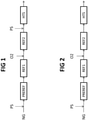
- Fig. 1 shows a first embodiment of the invention, where the front-end includes a pre-reformer PREREF upstream the primary reformer REF1.
- a natural gas feedstock NG is mixed with a first steam current PS and enters the pre-reformer PREREF.
- the pre-reformed gas leaving the pre-reformer is fed to the primary reformer REF1 and the gas leaving said primary reformer is fed to the oxygenfired autothermal secondary reformer REF2.
- the reformed gas leaving said secondary reformer REF2 is mixed with a second amount of steam PS, and then enters the high-temperature shift converter HTS which operates at around 320 - 500 °C with an iron based catalyst, to convert CO into CO2.
- the gas leaving said converter HTS is further treated according to known techniques, typically removal of carbon dioxide and (optionally) methanation.
- the removal of carbon dioxide may be carried out with any of the following techniques: In Fig. 1 , the pre-reformer and the primary reformer operate at a low steam-to-carbon ratio, for example around 1.5, while the addition of the second amount of steam PS before the shift converter HTS raises the global steam-to-carbon ratio to 2.2 - 2.4.
- Fig. 2 shows a process where the feed of the pre-reformer PREREF, that is the natural gas NG mixed with steam PS, has a steam-to-carbon ratio equal to said global ratio, and no further steam is added during the process. In particular, no further steam is added before the shift converter HTS.
- the steam-to-carbon ratio is preferably around 2.4.
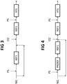
- Fig. 3 shows another embodiment, with no pre-reformer.
- a portion of the available feedstock bypasses the first steam reformer REF1. Accordingly, a first portion of the available feedstock NG is mixed with steam PS and enters the primary reformer REF1; a second remaining portion of said feedstock, on the other hand, is mixed the effluent of said primary reformer REF1. The resulting mixture is added with an oxygen stream O2 before it enters the secondary reformer REF2.
- a second amount of steam PS as in Fig. 1 , is mixed with the effluent of said secondary reformer REF2, before admission into the shift converter HTS.
- the steam reformer REF1 is run at a high steam-to-carbon ratio which is, for example, around 2.7 - 3, due to the portion of feedstock bypassing the reformer.
- said second portion of the feedstock NG, which bypasses the primary reformer is around 30% of the available feedstock.
- Fig. 4 shows another embodiment which is similar to Fig. 3 , but includes a prereformer PREREF.
- the bypass portion of feedstock as shown, bypasses both the pre-reformer and the primary reformer REF1.
- Fig. 5 shows another embodiment which is a variant of Fig. 4 .
- the full amount of natural gas NG, mixed with steam PS, is fed to the pre-reformer PREREF. However, a portion of the effluent of said pre-reformer bypasses the subsequent primary reformer REF1, being mixed with the gas leaving said primary reformer.
- a second amount of steam PS also in this case, is mixed with the effluent of the autothermal reformer REF2.
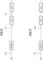
- Fig. 6 shows a further process.
- the full amount of natural gas NG, mixed with steam PS, is fed to the pre-reformer PREREF. There is no primary reformer.
- the product of pre-reforming is routed to the autothermal reformer ATR fired with oxygen.
- a second amount of steam PS is mixed with the effluent of the autothermal reformer.
- Fig. 7 shows a a further process, identical to 6 except for the autothermal reformer ATR being fired with air.
- Fig. 8 shows a process for revamping an existing line comprising a primary reformer REF1 and a secondary reformer REF2.
- Said line is revamped by adding a new line with an autothermal reformer ATR.
- the natural gas feed NG is split between the line comprising a primary reformer REF1 and a secondary reformer REF2, and the newly added line comprising a prereformer PREREF and an autothermal reformer ATR.
- Steam PS is added to the feed NG both at the inlet of primary reformer REF1 and of pre-reformer PREREF.
- the product of the secondary reformer REF2 and the product of autothermal ATR are joined upstream of the shift converter HTS, and mixed with steam PS
- the primary reformer REF1 operates preferably at a pressure around 30 bar, inlet temperature around 500 °C and outlet temperature around 750 - 800 °C.
- the outlet temperature of the secondary reformer REF2 is around 1000 °C.
- the outlet temperature of the autothermal reformer ATR is around 1000 °C.
- a low-temperature shift converter may be installed downstream the converter HTS. After the shift, a carbon dioxide removal section is normally provided. It should be noted that the synthesis gas does not contain nitrogen and hence the invention allows using a PSA (pressure swing absorption) or LNW (liquefied nitrogen wash).
- PSA pressure swing absorption
- LNW liquefied nitrogen wash
- the following table 1 compares a prior art front end with a primary steam reformer and a secondary reformer, and global steam-to-carbon ratio of 2.6, with five examples which relate, respectively, to embodiments and processes of Fig. 1, Fig. 2 , Fig. 3 , Fig 6 and Fig 7 .
- the examples relate to a production of 3275 kmol/h of hydrogen.
- SMR denotes the steam methane reforming
- RP denotes the reducing potential RP
- S/DG denotes the steam/dry gas ratio (see above definitions). Only examples 1 and 3 are according to the invention.
- Table 1 Prior art Ex.1 FIG. 1
- Ex. 2 ( Fig. 2 ) Ex.3 ( Fig. 3 )
- the table indicates also the values of the reducing potential RP and steam/dry gas S/DG, as above defined, which are such to allow the use of the iron based catalyst, despite the low steam-to-carbon ratio between 2 and 2.37 in the examples. It can be observed that the values of S/DG are highest for the cases with ATR only, and that the values of RP are lowest for the cases with ATR only, this suggests that even lower global S/C values can be used for the cases with ATR only.
- the following table 2 shows the reduced duty of the primary reformer, compared to the prior art.
Description
- The invention relates to reforming of hydrocarbons for the preparation of a synthesis gas for the production of ammonia.
- The synthesis of ammonia (NH3) requires a synthesis gas comprising hydrogen (H2) and nitrogen (N2) in a suitable ratio of about 3:1. The term ammonia syngas will be used with reference to a synthesis gas with the above composition.
- It is known to produce said ammonia syngas from the reforming of a desulphurized natural gas, by means of a primary steam reforming and subsequent secondary reforming of the effluent, see for example
EP 2 022 754 . - The gas leaving the secondary reformer needs purification, to remove carbon oxides and residual methane. According to the prior art, said purification includes the shift of the carbon monoxide (conversion of carbon monoxide into carbon dioxide), which is usually carried out in a high-temperature shift converter (HTS) over an iron based catalyst, and then in a low-temperature shift converter (LTS) over a copper based catalyst. The HTS converter operates at around 320-500 °C and the LTS converter operates at around 190-250 °C. After the shift, the syngas is treated by carbon dioxide removal and optionally methanation.
- An important parameter governing the process is the steam-to-carbon ratio, also referred to as SC ratio. The steam-to-carbon ratio is the molar ratio between water (steam) admitted to the process and the carbon contained in the feedstock of natural gas. The steam is normally admitted upstream of the primary reformer.
- There is an incentive to reduce said SC ratio, in order to reduce the flow rate and hence the size of the equipment, and also to reduce the energy consumption.
- It is commonly believed that the iron based catalyst of the high-temperature shift cannot operate in a reducing environment, which would deactivate the catalyst and cause undesired formation of by-products. It is believed that the lower limit of SC ratio, to be tolerable by said iron based catalyst, is generally around 2.6-2.8.
- For this reason, the SC ratio of a prior art front-end for the production of ammonia syngas by steam reforming with HTS converter is normally around 3.
- It has been observed that other parameters influencing the possibility to use an iron based catalyst are the reducing potential RP and steam/dry gas S/DG ratio of the incoming gas. Said parameters are a function of the molar composition of the gas, according to the following definitions:
RP = (H2 + CO) / (CO2 + H2O)
S/DG = H2O / (1-H2O)
- For use of an iron based catalyst, S/DG should be ideally around 0.4 or higher, and RP should be around 1.7 or lower.
- Said SC ratio around 3 is well above the stoichiometric value, since the primary reformer converts methane (CH4) and steam (H2O) into CO and H2 and hence the chemical reaction would theoretically require only one mole of steam for each mole of methane.
- The prior art teaches that a steam-to-carbon ratio lower than 2.6 requires necessarily to replace the high-temperature shift catalyst with a copper based medium-temperature shift (MTS) catalyst.
-
EP 2 404 869 , for example, discloses that synthesis gas delivered by secondary reforming is subject to a medium-temperature shift (MTS) over copper-based catalyst at a temperature between 200 and 350 °C, and primary reforming is operated with a steam-to-carbon ratio lower than 2. A corresponding method for revamping an ammonia plant is disclosed, where an existing HTS reactor is modified to operate at medium temperature, or replaced with a new MTS reactor, and the steam-to-carbon ratio in the primary reformer is lowered to a value in the range 1-5 - 2. - The use of an MTS converter instead of HTS converter however may introduce some disadvantages. Indeed, the HTS converter is preferred for some reasons: the iron based HTS catalyst is more resistant to poisoning (e.g. from sulphur) than the copper based MTS catalyst; a HTS converter can operate under a greater difference of temperature between inlet and outlet; the HTS converter is widely used in the front-ends of existing ammonia plants, and their revamping would be easier and less expensive if the existing HTS were maintained.
- The applicant has found that a high-temperature shift converter with an iron based catalyst can be used with a global steam-to-carbon ratio lower than 2.6.
- This is made in combination with a secondary reforming fired with oxygen or oxygen-enriched air instead of air. Values for said steam-to-carbon ratio range from 1.5 to 2.6. Said ratio is preferably 2 to 2.6 and more preferably 2.2 to 2.4.
- The term of oxygen denotes a substantially pure oxygen flow, with a high degree of purity as obtainable from an air separation unit (ASU). Enriched air denotes air having a content of oxygen which is at least 50% and preferably equal to or more than 90%.
- A first aspect of the invention, in accordance to the above, is a process according to claim 1 comprising the steps of:
- steam reforming of said feedstock, obtaining a synthesis gas comprising hydrogen, carbon monoxide and carbon dioxide;
- a treatment of said synthesis gas including shift of carbon monoxide and subsequent removal of carbon dioxide,
- characterized in that:
- the shift of the synthesis gas includes a step of high-temperature shift with an iron-based catalyst;
- the global steam-to-carbon ratio of the front end is 1.5 to 2.6 or less.
- The term of global steam-to-carbon ratio is used in this description to denote the ratio between the moles of steam and moles of carbon which are admitted to the process, including any feed of hydrocarbon and any feed of steam up to the inlet of the high temperature shift. Hence said global ratio is calculated for the overall process, and takes into account all additional feeds of steam, when provided. Some embodiments of the invention, for example, include more than one feed of steam, for example a first steam flow before a primary reformer or pre-reformer, and a second steam flow before the HTS converter. In such a case, all the steam feeds are considered for the calculation of the global ratio.
- The applicant has found that, in the above case, the water produced in the secondary reformer fired with oxygen or oxygen enriched air, by reaction of hydrogen and methane with the oxygen, is significantly higher compared to the conventional air-fired process. Accordingly, the amount of steam directed to the reforming can be reduced, being compensated by the water which is internally produced by the process, particularly in the secondary reformer. In particular, the applicant has found that the global steam-to-carbon ratio of the front end can be significantly lower than 2.6, still using a HTS converter. This finding is in sharp contrast with the prior art, where 2.6 was considered the lower bound for use of high-temperature shift.
- Preferably, the temperature of the high-temperature shift is greater than 300 °C and more preferably in the range 320 to 500 °C.
- Some embodiments of the invention include a pre-reforming stage, which means that a pre-reformer is installed upstream the primary reformer.
- The hydrocarbon feedstock is preferably a desulphurized natural gas. The feedstock is normally mixed with steam before the primary reforming or, when provided, before the pre-reforming step. In the invention, at least one further addition of steam is provided, whereby the effluent of the secondary reforming step is mixed with a further steam, before the high-temperature shift step. This further addition of steam is a feature provided to ensure a proper operation of the HTS converter.
- Various embodiments of the invention may provide any of the following features, or a combination thereof:
- mixing an amount of the fresh hydrocarbon feedstock with the effluent of the primary steam reforming, prior to the second reforming step;
- when pre-reforming is effected, mixing a portion of pre-reformed gas with the effluent of the primary steam reforming, said portion of pre-reformed gas bypassing the step of primary reforming
- In accordance, the steam-to-carbon ratio of the pre-reforming or of the primary reforming step may vary, despite the global ratio being 1.5 to 2.6 as desired. Some preferred embodiments are stated in the dependent claims.
- For example, a preferred embodiment provides that said first reforming step includes a pre-reforming and a primary steam reforming, the pre-reforming is carried out with a first steam-to-carbon ratio and the primary steam reforming is carried out with a second steam-to-carbon ratio which is equal to or greater than said first ratio, while both said first and second ratio are lower than the global ratio. Preferably, said first ratio is in the range 0.5 to 2, while said second ratio is around 1.5 - 2. Then, the synthesis gas obtained after the second reforming step is mixed with steam, prior to its feeding to high-temperature shift, raising the global steam-to-carbon ratio of the front end.
- Adding steam upstream of the HTS converter has the advantage of less steam in the pre-reformer, primary reformer and secondary reformer. This is preferred, in particular, when an existing front-end is revamped according to the invention, since it reduces the duty of the primary reformer (which is often a bottleneck of the plant) and of the waste heat boiler which is normally installed downstream the secondary reformer. Revamping these items is expensive and, hence, a reduction of their duty is an advantage.
- Described herein is also a method not according to the present invention of revamping a front-end of an ammonia plant, wherein said front-end comprises a primary reforming stage and an air-fired secondary reforming stage, and also comprises a high-temperature shift converter with an iron based catalyst and running at a temperature greater than 320 °C, and wherein the original front-end operates with a global steam-to-carbon ratio of 2.6 or greater. The method is characterized in that the secondary reforming stage is modified to operate with oxygen or oxygen-enriched air, with at least 50% oxygen, as oxidant stream, instead of air, and in that the amount of the hydrocarbon feedstock and the amount of steam fed to the front-end are regulated in such a way that the global steam-to-carbon ratio of the revamped front-end is 2.6 or less.
- The above can be accomplished by replacing the existing secondary reformer with a new secondary reformer, or by modifying the existing secondary reformer. The method will normally include the provision of a line feeding oxygen or oxygen-enriched air to the secondary reformer and, if necessary, of means to provide said oxygen (or oxygen for air enrichment), such as an air separation unit (ASU).
- Another revamping method can be accomplished by adding a new ATR in parallel to the existing primary and secondary reformers, the new ATR optionally preceded by a pre-reformer, and mixing the effluent of the ATR with the effluent of the existing secondary reformer upstream the HTS. The global S/C ratio (calculated as the total steam divided by the total carbon moles added to the existing primary and secondary reformers and HTS and new ATR and prereformer if installed) is less than 2.6
- The method may include the installation of a steam line for the addition a predetermined amount of steam to the synthesis gas leaving the secondary reforming stage, prior to admission into the high-temperature shift converter, in order to regulate the global SC ratio. In some embodiments, the method comprises the installation of a bypass line of the reforming stage, arranged in such a way that a portion of the feedstock bypasses the first reforming stage and is sent directly to the second reforming stage. In further embodiments, the primary reforming stage includes a pre-reformer, the method may include the provision of a bypass line of the primary reformer for a portion of the effluent of said pre-reformer, so that said portion is sent directly to the second reforming stage.
- It can be said that the invention, in comparison with the prior art, reduces the admission of steam (and, hence, the SC ratio) by introducing more oxygen in the secondary reforming stage, which is now fed with oxygen or oxygen enriched air instead of air. The applicant has found that, although an oxygen or rich air feed is expensive to provide, this solution proves to be convenient, since the flow rates are greatly reduced and, surprisingly, a HTS converter can be used at steam-to-carbon ratio much lower than prior art.
- An advantage of the invention is that, for a given production, the duty of the primary steam reformer is reduced by around 10 - 20% or even more. The synthesis gas flow (m3/h) through the front-end, for a given production of ammonia, can be reduced by around 30%, which is a great advantage in terms of size/cost of the plant.
- Regarding revamping, the above advantage can be turned into more capacity with the existing equipment. As mentioned above, the existing plant commonly use a HTS converter and keeping said HTS (despite the low SC ratio) is an advantage, which means no need of expensive replacement of the converter and/or the catalyst.
- A feature of the invention is a reduction of the duty of the primary reformer. The duty of the primary reformer, and of the secondary reformer as well, can be calculated referring to heat value [MW] of the fuel consumed in the primary or secondary reformer. A specific duty can be defined with reference to tons of ammonia produced. In the prior art, the duty of the primary reformer is commonly greater than that of the secondary reformer, e.g. the duty of the primary reformer around 140% of the duty of the secondary reformer. According to some embodiments of the invention, the duty of the primary reformer is equal to or even lower than the duty of the secondary reformer. In preferred embodiments, the duty of the primary reformer is 70-100% of the duty of the secondary reformer.
- The invention will be elucidated with reference to
Figs. 1 to 8 , wherein: -
Figs. 1 and3-5 are schemes of embodiments of the invention with primary and secondary reforming; -
Figs. 2 ,6 to 8 are schemes of processes not according to the invention. - Referring to
Figs. 1 to 8 : - PREREF denotes a pre-reformer,
- REF1 denotes a primary steam reformer, which is usually a tube reformer,
- REF2 denotes a secondary reformer,
- ATR denotes an autothermal reformer (ATR) if no upstream primary reformer (REF1) is installed
- HTS denotes a high-temperature shift converter,
- PS denotes a flow of steam,
- NG denotes a feedstock of natural gas,
- O2 denotes a current of oxygen or oxygen-rich air which is the oxidant stream fed to the secondary reformer REF2.
-
Fig. 1 shows a first embodiment of the invention, where the front-end includes a pre-reformer PREREF upstream the primary reformer REF1. A natural gas feedstock NG is mixed with a first steam current PS and enters the pre-reformer PREREF. The pre-reformed gas leaving the pre-reformer is fed to the primary reformer REF1 and the gas leaving said primary reformer is fed to the oxygenfired autothermal secondary reformer REF2. The reformed gas leaving said secondary reformer REF2 is mixed with a second amount of steam PS, and then enters the high-temperature shift converter HTS which operates at around 320 - 500 °C with an iron based catalyst, to convert CO into CO2. Then, the gas leaving said converter HTS is further treated according to known techniques, typically removal of carbon dioxide and (optionally) methanation. - The removal of carbon dioxide may be carried out with any of the following techniques:
InFig. 1 , the pre-reformer and the primary reformer operate at a low steam-to-carbon ratio, for example around 1.5, while the addition of the second amount of steam PS before the shift converter HTS raises the global steam-to-carbon ratio to 2.2 - 2.4. -
Fig. 2 shows a process where the feed of the pre-reformer PREREF, that is the natural gas NG mixed with steam PS, has a steam-to-carbon ratio equal to said global ratio, and no further steam is added during the process. In particular, no further steam is added before the shift converter HTS. In this process, the steam-to-carbon ratio is preferably around 2.4. -
Fig. 3 shows another embodiment, with no pre-reformer. A portion of the available feedstock bypasses the first steam reformer REF1. Accordingly, a first portion of the available feedstock NG is mixed with steam PS and enters the primary reformer REF1; a second remaining portion of said feedstock, on the other hand, is mixed the effluent of said primary reformer REF1. The resulting mixture is added with an oxygen stream O2 before it enters the secondary reformer REF2. A second amount of steam PS, as inFig. 1 , is mixed with the effluent of said secondary reformer REF2, before admission into the shift converter HTS. - In this case, the steam reformer REF1 is run at a high steam-to-carbon ratio which is, for example, around 2.7 - 3, due to the portion of feedstock bypassing the reformer. Preferably, said second portion of the feedstock NG, which bypasses the primary reformer, is around 30% of the available feedstock.
-
Fig. 4 shows another embodiment which is similar toFig. 3 , but includes a prereformer PREREF. The bypass portion of feedstock, as shown, bypasses both the pre-reformer and the primary reformer REF1. -
Fig. 5 shows another embodiment which is a variant ofFig. 4 . The full amount of natural gas NG, mixed with steam PS, is fed to the pre-reformer PREREF. However, a portion of the effluent of said pre-reformer bypasses the subsequent primary reformer REF1, being mixed with the gas leaving said primary reformer. A second amount of steam PS, also in this case, is mixed with the effluent of the autothermal reformer REF2. -
Fig. 6 shows a further process. The full amount of natural gas NG, mixed with steam PS, is fed to the pre-reformer PREREF. There is no primary reformer. - The product of pre-reforming is routed to the autothermal reformer ATR fired with oxygen. A second amount of steam PS is mixed with the effluent of the autothermal reformer.
-
Fig. 7 shows a a further process, identical to 6 except for the autothermal reformer ATR being fired with air. -
Fig. 8 shows a process for revamping an existing line comprising a primary reformer REF1 and a secondary reformer REF2. Said line is revamped by adding a new line with an autothermal reformer ATR. The natural gas feed NG is split between the line comprising a primary reformer REF1 and a secondary reformer REF2, and the newly added line comprising a prereformer PREREF and an autothermal reformer ATR. Steam PS is added to the feed NG both at the inlet of primary reformer REF1 and of pre-reformer PREREF. The product of the secondary reformer REF2 and the product of autothermal ATR are joined upstream of the shift converter HTS, and mixed with steam PS - In all the above embodiments and processes, the primary reformer REF1 operates preferably at a pressure around 30 bar, inlet temperature around 500 °C and outlet temperature around 750 - 800 °C. The outlet temperature of the secondary reformer REF2 is around 1000 °C. The outlet temperature of the autothermal reformer ATR is around 1000 °C.
- In all the above embodiments and processes, a low-temperature shift converter may be installed downstream the converter HTS. After the shift, a carbon dioxide removal section is normally provided. It should be noted that the synthesis gas does not contain nitrogen and hence the invention allows using a PSA (pressure swing absorption) or LNW (liquefied nitrogen wash).
- The following table 1 compares a prior art front end with a primary steam reformer and a secondary reformer, and global steam-to-carbon ratio of 2.6, with five examples which relate, respectively, to embodiments and processes of
Fig. 1, Fig. 2 ,Fig. 3 ,Fig 6 and Fig 7 . The examples relate to a production of 3275 kmol/h of hydrogen. In the table, SMR denotes the steam methane reforming; RP denotes the reducing potential RP and S/DG denotes the steam/dry gas ratio (see above definitions). Only examples 1 and 3 are according to the invention.Table 1 Prior art Ex.1 ( FIG. 1 )Ex. 2 ( Fig. 2 )Ex.3 ( Fig. 3 )Ex. 4 ( Fig 6 )Ex. 5 ( Fig 7 )S/C ratio, overall 2.6 2.2 2.37 2.15 2.1 1.9 S/C inlet SMR 2.6 1.5 2.37 2.7 N/A N/A S/C inlet Prereformer - 1.5 2.37 - 1.0 0.5 S/DG, inlet HTS 0.40 0.51 0.48 0.48 0.68 0.43 RP, inlet HTS 1.47 1.64 1.64 1.65 1.2 1.2 Natural Gas [kmol/h] 1008 1054 998 1048 1208 1436 Steam [kmol/h] 2722 2318 2366 2254 2537 2729 Oxygen [kmol/h] (process air) 377 337 420 733 626 (1) Hydrogen [kmol/h] 3275 3275 3275 3275 3275 3275 SMR cat.tubes duty [MW] 44.6 32.8 39.3 33.1 0 0 100% 74% 88% 74% 0% 0% Syngas flow rate [t/h] 106 71 69 71 74 168 (2) 100% 67% 66% 67% 70% 94% (3) (1) (in the air stream)
(2) (99 excluding N2)
(3) (based on flow excluding N2) - It can be noted that the duty of the steam methane reformer (primary reformer) is lower by 26% (ex. 1), 12% (ex. 2) and 26% (ex. 3), despite the same production of hydrogen. Furthermore, the syngas flow rate is considerably lower, being around 66-67% of the prior-art, also due to firing of the secondary reformer with oxygen instead of air. The size of a new plant can be reduced accordingly or, in a revamping, a larger capacity for a given size can be obtained.
- The table indicates also the values of the reducing potential RP and steam/dry gas S/DG, as above defined, which are such to allow the use of the iron based catalyst, despite the low steam-to-carbon ratio between 2 and 2.37 in the examples. It can be observed that the values of S/DG are highest for the cases with ATR only, and that the values of RP are lowest for the cases with ATR only, this suggests that even lower global S/C values can be used for the cases with ATR only.
- The following table 2 shows the reduced duty of the primary reformer, compared to the prior art.
- Values for examples 4 and 5 are not indicated (the steam reformer duty is zero).
Table 2 Prior art Ex. 1 ( FIG. 1 )Ex. 2 ( Fig. 2 )Ex. 3 ( Fig. 3 )NH3 production based on 3275 kmol/h H2 flow [t/h] 37 37 37 37 SMR duty [MW] 45 33 39 33 Specific SMR duty [MWh/t NH3] 1.2 0.9 1.1 0.9 Fuel burnt in ATR (assumed 100% CH4) [kmol/h] 145 189 169 210 ATR duty [MW] 32 42 38 47 Specific ATR duty [MWh/t NH3] 0.9 1.1 1.0 1.3 Specific SMR+ATR duty [MWh/t NH3] 2.1 2.0 2.1 2.2 SMR/ATR duty 138% 78% 104% 71%
Claims (6)
- A process for producing ammonia synthesis gas from a hydrocarboncontaining feedstock in a front-end, the process comprising the steps of:steam reforming of said feedstock, obtaining a synthesis gas comprising hydrogen, carbon monoxide and carbon dioxide;a treatment of said synthesis gas including shift of carbon monoxide and subsequent removal of carbon dioxide,characterized in that:the shift of the synthesis gas includes a step of high-temperature shift with an iron-based catalyst;said steam reforming comprises:a first reforming step including a primary steam reforming and optionally including a pre-reforming before said primary steam reforming, thus obtaining a first reformed gas;a secondary reforming fired with a stream of an oxidant, thus obtaining a synthesis gas comprising hydrogen, carbon monoxide and carbon dioxide;said first reforming step and said secondary reforming being performed in series,said secondary reforming being carried out by using oxygen or enriched air comprising at least 50% oxygen, as the oxidant stream; and whereinthe synthesis gas obtained after said secondary reforming being then mixed with steam, prior to its feeding to high-temperature shift, so that the global steam-to-carbon molar ratio of the front end is 1.5 to 2.6, the global steam-to-carbon molar ratio being the ratio between the moles of steam and moles of carbon which are admitted to the process, including any feed of hydrocarbon and any feed of steam up to the inlet of the high temperature shift.
- A process according to claim 1, said global steam-to-carbon molar ratio being in the range 2.2 to 2.4.
- A process according to claim 1, where said first reforming step includes a pre-reforming step, and where the pre-reforming and the primary steam reforming are carried out with a low steam-to-carbon molar ratio which is lower than said global molar ratio, said low steam-to-carbon molar ratio being preferably less than 2 and more preferably around 1.5.
- A process according to claim 1, wherein the primary steam reforming is carried out with a steam-to-carbon molar ratio which is greater than said global molar ratio, and an amount of fresh hydrocarbon feedstock is mixed with the effluent of the primary steam reforming, prior to said secondary reforming, said steam-to-carbon molar ratio of the primary steam reforming being preferably in the range 2.7 to 3.
- A process according to claim 1, characterized in that said first reforming step includes a pre-reforming and a primary steam reforming, the pre-reforming is carried out with a first steam-to-carbon molar ratio and the primary steam reforming is carried out with a second steam-to-carbon molar ratio which is equal to or greater than said first molar ratio, while both said first and second molar ratio are lower than the global molar ratio, said first molar ratio being preferably selected in the range 0.5 to 2 and said second molar ratio being preferably around 1.5 - 2.
- A process according to claim 5, characterized in that:the effluent of the primary steam reforming step is mixed with an amount of fresh hydrocarbon, and/oran amount of the pre-reformed gas leaving said pre-reforming step is mixed with the effluent of the primary steam reforming, thus bypassing said primary reforming.
Applications Claiming Priority (2)
| Application Number | Priority Date | Filing Date | Title |
|---|---|---|---|
| EP13167211.5A EP2801550A1 (en) | 2013-05-10 | 2013-05-10 | A process for producing ammonia synthesis gas with high temperature shift and low steam-to-carbon ratio |
| PCT/EP2014/059055 WO2014180763A1 (en) | 2013-05-10 | 2014-05-05 | A process for producing ammonia synthesis gas with high temperature shift and low steam-to-carbon ratio |
Publications (2)
| Publication Number | Publication Date |
|---|---|
| EP2994415A1 EP2994415A1 (en) | 2016-03-16 |
| EP2994415B1 true EP2994415B1 (en) | 2022-03-02 |
Family
ID=48446087
Family Applications (2)
| Application Number | Title | Priority Date | Filing Date |
|---|---|---|---|
| EP13167211.5A Withdrawn EP2801550A1 (en) | 2013-05-10 | 2013-05-10 | A process for producing ammonia synthesis gas with high temperature shift and low steam-to-carbon ratio |
| EP14721380.5A Active EP2994415B1 (en) | 2013-05-10 | 2014-05-05 | A process for producing ammonia synthesis gas with high temperature shift and low steam-to-carbon ratio |
Family Applications Before (1)
| Application Number | Title | Priority Date | Filing Date |
|---|---|---|---|
| EP13167211.5A Withdrawn EP2801550A1 (en) | 2013-05-10 | 2013-05-10 | A process for producing ammonia synthesis gas with high temperature shift and low steam-to-carbon ratio |
Country Status (11)
| Country | Link |
|---|---|
| US (1) | US10173895B2 (en) |
| EP (2) | EP2801550A1 (en) |
| CN (1) | CN105189340B (en) |
| AU (1) | AU2014264791A1 (en) |
| BR (1) | BR112015028220B1 (en) |
| CA (1) | CA2910356C (en) |
| CL (1) | CL2015003260A1 (en) |
| MY (1) | MY179281A (en) |
| RU (1) | RU2666897C2 (en) |
| SA (1) | SA515370126B1 (en) |
| WO (1) | WO2014180763A1 (en) |
Families Citing this family (12)
| Publication number | Priority date | Publication date | Assignee | Title |
|---|---|---|---|---|
| EP2993158A1 (en) | 2014-09-05 | 2016-03-09 | Casale SA | Process for production of ammonia and derivatives, in particular urea |
| BR112018014726B1 (en) | 2016-02-02 | 2023-04-18 | Haldor Tops0E A/S | PROCESS FOR THE PRODUCTION OF AN AMMONIA SYNTHESIS GAS |
| GB201603298D0 (en) * | 2016-02-25 | 2016-04-13 | Johnson Matthey Plc | Process |
| AR107702A1 (en) * | 2016-02-29 | 2018-05-23 | Haldor Topsoe As | RENEWAL WITH LOW AMOUNT OF STEAM / CARBON |
| CN106147868A (en) * | 2016-08-30 | 2016-11-23 | 安徽金禾实业股份有限公司 | A kind of ammonia oxygen enhanced gasification production method |
| EP3363770A1 (en) * | 2017-02-15 | 2018-08-22 | Casale Sa | Process for the synthesis of ammonia with low emissions of co2 in atmosphere |
| CN110267916A (en) * | 2017-03-07 | 2019-09-20 | 托普索公司 | Use the ammonia method of advanced conversion process |
| DK3401280T3 (en) | 2017-05-11 | 2022-03-21 | Gascontec Gmbh | METHOD OF PREPARING AMMONIA |
| CN107337178B (en) * | 2017-06-05 | 2020-01-14 | 华南理工大学 | Process for recycling PSA desorption gas and catalytic regeneration flue gas of oil refinery |
| KR20240005207A (en) * | 2017-07-13 | 2024-01-11 | 토프쉐 에이/에스 | Method and catalysts for the production of ammonia synthesis gas |
| WO2020174056A1 (en) * | 2019-02-28 | 2020-09-03 | Haldor Topsøe A/S | Chemical plant with a reforming section and a process for producing a chemical product |
| CA3127155A1 (en) * | 2019-02-28 | 2020-09-03 | Haldor Topsoe A/S | Parallel reforming in chemical plant |
Citations (6)
| Publication number | Priority date | Publication date | Assignee | Title |
|---|---|---|---|---|
| EP0001329A1 (en) | 1977-09-16 | 1979-04-04 | Imperial Chemical Industries Plc | Process and plant for producing ammonia |
| US4479925A (en) | 1982-09-13 | 1984-10-30 | The M. W. Kellogg Company | Preparation of ammonia synthesis gas |
| WO2009068159A1 (en) | 2007-11-27 | 2009-06-04 | Ammonia Casale S.A. | Process for producing ammonia synthesis gas |
| WO2010020309A1 (en) | 2008-08-22 | 2010-02-25 | Haldor Topsøe A/S | Process for production of synthesis gas |
| WO2011018388A2 (en) | 2009-08-13 | 2011-02-17 | Ammonia Casale Sa | Process for revamping an ammonia plant with nitrogen-based washing of a purge stream |
| WO2013013865A1 (en) | 2011-07-27 | 2013-01-31 | Robert Bosch Gmbh | Piston pump for delivering fluids, and corresponding assembly process for a piston pump |
Family Cites Families (27)
| Publication number | Priority date | Publication date | Assignee | Title |
|---|---|---|---|---|
| FR2473032A1 (en) * | 1980-01-07 | 1981-07-10 | Banquy David | PROCESS FOR THE PRODUCTION OF AMMONIA AND THE SYNTHESIS GAS CORRESPONDING |
| EP0157480B1 (en) * | 1984-03-02 | 1989-07-26 | Imperial Chemical Industries Plc | Process for producing ammonia synthesis gas |
| DE10055818A1 (en) * | 2000-11-10 | 2002-05-23 | Ammonia Casale Sa | Catalytic production of ammonia, especially for direct conversion into urea, using nitrogen-hydrogen starting gas mixture obtained from natural gas by autothermal reforming and catalytic conversion |
| RU2228901C2 (en) * | 2002-01-09 | 2004-05-20 | Институт нефтехимического синтеза им. А.В. Топчиева РАН | Synthesis gas production process |
| EP1622827A1 (en) * | 2003-04-15 | 2006-02-08 | Shell Internationale Researchmaatschappij B.V. | Reactor for performing a steam reforming reaction and a process to prepare synthesis gas |
| DE102004014292A1 (en) * | 2004-03-22 | 2005-10-20 | Lurgi Ag | Co-production of methanol and ammonia from natural gas |
| US20060013759A1 (en) * | 2004-07-13 | 2006-01-19 | Conocophillips Company | Systems and methods for hydrogen production |
| US7510696B2 (en) * | 2005-02-07 | 2009-03-31 | Air Products And Chemicals, Inc. | Method and apparatus for the production of hydrogen-rich gas |
| US7695708B2 (en) * | 2007-03-26 | 2010-04-13 | Air Products And Chemicals, Inc. | Catalytic steam reforming with recycle |
| EP2361878B1 (en) * | 2007-07-27 | 2015-10-07 | Nippon Oil Corporation | Method and apparatus for hydrogen production and carbon dioxide recovery |
| EP2022754A1 (en) | 2007-08-08 | 2009-02-11 | Ammonia Casale S.A. | Process for producing ammonia synthesis gas |
| US8323363B2 (en) * | 2007-08-30 | 2012-12-04 | Innovative Energy Solution | Reformation of hydrogen-containing fluids in a cyclic flow reactor |
| US7790059B2 (en) * | 2007-10-18 | 2010-09-07 | Air Products And Chemicals, Inc. | Staged hydrocarbon/steam reformer apparatus and method |
| WO2009069220A1 (en) * | 2007-11-29 | 2009-06-04 | Jgc Corporation | Process and apparatus for production of raw gas for ammonia synthesis |
| US8119558B2 (en) * | 2008-03-14 | 2012-02-21 | Süd-Chemie Inc. | Ultra high temperature shift catalyst with low methanation |
| PL2141118T3 (en) * | 2008-07-03 | 2014-01-31 | Haldor Topsoe As | Chromium-free water gas shift catalyst |
| US9132401B2 (en) * | 2008-07-16 | 2015-09-15 | Kellog Brown & Root Llc | Systems and methods for producing substitute natural gas |
| US8124049B2 (en) * | 2008-10-29 | 2012-02-28 | Air Liquide Process & Construction, Inc. | Zero steam export with CO2 recovery in a high thermal efficiency hydrogen plant |
| US8617270B2 (en) * | 2008-12-03 | 2013-12-31 | Kellogg Brown & Root Llc | Systems and methods for improving ammonia synthesis efficiency |
| EP2199254A1 (en) * | 2008-12-11 | 2010-06-23 | BP p.l.c. | Integrated gas refinery |
| GB0901472D0 (en) * | 2009-01-30 | 2009-03-11 | Johnson Matthey Plc | Hydrogen process |
| CA2750866C (en) * | 2009-04-15 | 2014-07-29 | Air Products And Chemicals, Inc. | Process for producing a hydrogen-containing product gas |
| US9321655B2 (en) * | 2009-08-20 | 2016-04-26 | Kellogg Brown & Root Llc | Systems and methods for producing syngas and products therefrom |
| GB0922410D0 (en) * | 2009-12-22 | 2010-02-03 | Johnson Matthey Plc | Conversion of hydrocarbons to carbon dioxide and electrical power |
| EP2404869A1 (en) | 2010-07-06 | 2012-01-11 | Ammonia Casale S.A. | Process for producing ammonia synthesis gas |
| WO2012177136A1 (en) * | 2011-06-23 | 2012-12-27 | Stamicarbon B.V. Acting Under The Name Of Mt Innovation Center | Process for producing a syngas intermediate suitable for the production of hydrogen |
| EA030740B1 (en) * | 2011-07-26 | 2018-09-28 | СТАМИКАРБОН Б.В. ЭКТИНГ АНДЕР ДЗЕ НЕЙМ ОФ ЭмТи ИННОВЕЙШН СЕНТЕР | Process for production of hydrogen rich gas mixtures |
-
2013
- 2013-05-10 EP EP13167211.5A patent/EP2801550A1/en not_active Withdrawn
-
2014
- 2014-05-05 BR BR112015028220-2A patent/BR112015028220B1/en active IP Right Grant
- 2014-05-05 AU AU2014264791A patent/AU2014264791A1/en not_active Abandoned
- 2014-05-05 MY MYPI2015703951A patent/MY179281A/en unknown
- 2014-05-05 US US14/889,943 patent/US10173895B2/en active Active
- 2014-05-05 CN CN201480026437.0A patent/CN105189340B/en active Active
- 2014-05-05 CA CA2910356A patent/CA2910356C/en active Active
- 2014-05-05 RU RU2015152848A patent/RU2666897C2/en active
- 2014-05-05 EP EP14721380.5A patent/EP2994415B1/en active Active
- 2014-05-05 WO PCT/EP2014/059055 patent/WO2014180763A1/en active Application Filing
-
2015
- 2015-11-06 CL CL2015003260A patent/CL2015003260A1/en unknown
- 2015-11-10 SA SA515370126A patent/SA515370126B1/en unknown
Patent Citations (6)
| Publication number | Priority date | Publication date | Assignee | Title |
|---|---|---|---|---|
| EP0001329A1 (en) | 1977-09-16 | 1979-04-04 | Imperial Chemical Industries Plc | Process and plant for producing ammonia |
| US4479925A (en) | 1982-09-13 | 1984-10-30 | The M. W. Kellogg Company | Preparation of ammonia synthesis gas |
| WO2009068159A1 (en) | 2007-11-27 | 2009-06-04 | Ammonia Casale S.A. | Process for producing ammonia synthesis gas |
| WO2010020309A1 (en) | 2008-08-22 | 2010-02-25 | Haldor Topsøe A/S | Process for production of synthesis gas |
| WO2011018388A2 (en) | 2009-08-13 | 2011-02-17 | Ammonia Casale Sa | Process for revamping an ammonia plant with nitrogen-based washing of a purge stream |
| WO2013013865A1 (en) | 2011-07-27 | 2013-01-31 | Robert Bosch Gmbh | Piston pump for delivering fluids, and corresponding assembly process for a piston pump |
Non-Patent Citations (3)
| Title |
|---|
| "Ammonia", ULLMANN ENCYCLOPEDIA OF INDUSTRIAL CHEMISTRY, vol. A2, 1985, pages 44 - 107, XP093011478 |
| 1 January 2004, article GARY MAXWELL A: "Synthetic Nitrogen Products: A Practical Guide to the Products and Processes", XP093011477 |
| ANONYMOUS: "MaxAppl Ammonia Principles and Industrial Practice", WILEY-VCH, 1 January 1999 (1999-01-01), pages 1 - 305, XP055932846, [retrieved on 20220618] |
Also Published As
| Publication number | Publication date |
|---|---|
| CA2910356C (en) | 2021-12-07 |
| WO2014180763A1 (en) | 2014-11-13 |
| SA515370126B1 (en) | 2018-08-02 |
| RU2666897C2 (en) | 2018-09-13 |
| CL2015003260A1 (en) | 2016-09-16 |
| US10173895B2 (en) | 2019-01-08 |
| BR112015028220A2 (en) | 2017-07-25 |
| EP2801550A1 (en) | 2014-11-12 |
| MY179281A (en) | 2020-11-03 |
| CN105189340B (en) | 2019-08-27 |
| CA2910356A1 (en) | 2014-11-13 |
| EP2994415A1 (en) | 2016-03-16 |
| RU2015152848A (en) | 2017-06-16 |
| CN105189340A (en) | 2015-12-23 |
| US20160115017A1 (en) | 2016-04-28 |
| AU2014264791A1 (en) | 2015-11-12 |
| BR112015028220B1 (en) | 2021-09-08 |
Similar Documents
| Publication | Publication Date | Title |
|---|---|---|
| EP2994415B1 (en) | A process for producing ammonia synthesis gas with high temperature shift and low steam-to-carbon ratio | |
| US20190023565A1 (en) | Process for producing ammonia synthesis gas | |
| EP2227435B1 (en) | Process for producing ammonia synthesis gas | |
| CN107021450B (en) | Process for the preparation of ammonia and urea | |
| EP2178791B1 (en) | Process for producing ammonia synthesis gas | |
| CN105209373B (en) | The method of co-producing ammine, urea and methanol | |
| MX2014010225A (en) | Process for producing ammonia synthesis gas and a related front-end of an ammonia plant. | |
| US9802820B2 (en) | Plant for hydrogen production | |
| EP3083490B1 (en) | Process for producing ammonia synthesis gas | |
| WO2023180114A1 (en) | Process for co-producing ammonia and methanol with reduced carbon |
Legal Events
| Date | Code | Title | Description |
|---|---|---|---|
| PUAI | Public reference made under article 153(3) epc to a published international application that has entered the european phase |
Free format text: ORIGINAL CODE: 0009012 |
|
| 17P | Request for examination filed |
Effective date: 20151125 |
|
| AK | Designated contracting states |
Kind code of ref document: A1 Designated state(s): AL AT BE BG CH CY CZ DE DK EE ES FI FR GB GR HR HU IE IS IT LI LT LU LV MC MK MT NL NO PL PT RO RS SE SI SK SM TR |
|
| AX | Request for extension of the european patent |
Extension state: BA ME |
|
| DAX | Request for extension of the european patent (deleted) | ||
| STAA | Information on the status of an ep patent application or granted ep patent |
Free format text: STATUS: EXAMINATION IS IN PROGRESS |
|
| 17Q | First examination report despatched |
Effective date: 20170206 |
|
| STAA | Information on the status of an ep patent application or granted ep patent |
Free format text: STATUS: EXAMINATION IS IN PROGRESS |
|
| GRAP | Despatch of communication of intention to grant a patent |
Free format text: ORIGINAL CODE: EPIDOSNIGR1 |
|
| STAA | Information on the status of an ep patent application or granted ep patent |
Free format text: STATUS: GRANT OF PATENT IS INTENDED |
|
| INTG | Intention to grant announced |
Effective date: 20211117 |
|
| GRAS | Grant fee paid |
Free format text: ORIGINAL CODE: EPIDOSNIGR3 |
|
| GRAA | (expected) grant |
Free format text: ORIGINAL CODE: 0009210 |
|
| STAA | Information on the status of an ep patent application or granted ep patent |
Free format text: STATUS: THE PATENT HAS BEEN GRANTED |
|
| AK | Designated contracting states |
Kind code of ref document: B1 Designated state(s): AL AT BE BG CH CY CZ DE DK EE ES FI FR GB GR HR HU IE IS IT LI LT LU LV MC MK MT NL NO PL PT RO RS SE SI SK SM TR |
|
| REG | Reference to a national code |
Ref country code: GB Ref legal event code: FG4D |
|
| REG | Reference to a national code |
Ref country code: CH Ref legal event code: EP Ref country code: AT Ref legal event code: REF Ref document number: 1472126 Country of ref document: AT Kind code of ref document: T Effective date: 20220315 |
|
| REG | Reference to a national code |
Ref country code: DE Ref legal event code: R096 Ref document number: 602014082674 Country of ref document: DE |
|
| REG | Reference to a national code |
Ref country code: IE Ref legal event code: FG4D |
|
| REG | Reference to a national code |
Ref country code: LT Ref legal event code: MG9D |
|
| REG | Reference to a national code |
Ref country code: NL Ref legal event code: MP Effective date: 20220302 |
|
| PG25 | Lapsed in a contracting state [announced via postgrant information from national office to epo] |
Ref country code: SE Free format text: LAPSE BECAUSE OF FAILURE TO SUBMIT A TRANSLATION OF THE DESCRIPTION OR TO PAY THE FEE WITHIN THE PRESCRIBED TIME-LIMIT Effective date: 20220302 Ref country code: RS Free format text: LAPSE BECAUSE OF FAILURE TO SUBMIT A TRANSLATION OF THE DESCRIPTION OR TO PAY THE FEE WITHIN THE PRESCRIBED TIME-LIMIT Effective date: 20220302 Ref country code: NO Free format text: LAPSE BECAUSE OF FAILURE TO SUBMIT A TRANSLATION OF THE DESCRIPTION OR TO PAY THE FEE WITHIN THE PRESCRIBED TIME-LIMIT Effective date: 20220602 Ref country code: LT Free format text: LAPSE BECAUSE OF FAILURE TO SUBMIT A TRANSLATION OF THE DESCRIPTION OR TO PAY THE FEE WITHIN THE PRESCRIBED TIME-LIMIT Effective date: 20220302 Ref country code: HR Free format text: LAPSE BECAUSE OF FAILURE TO SUBMIT A TRANSLATION OF THE DESCRIPTION OR TO PAY THE FEE WITHIN THE PRESCRIBED TIME-LIMIT Effective date: 20220302 Ref country code: ES Free format text: LAPSE BECAUSE OF FAILURE TO SUBMIT A TRANSLATION OF THE DESCRIPTION OR TO PAY THE FEE WITHIN THE PRESCRIBED TIME-LIMIT Effective date: 20220302 Ref country code: BG Free format text: LAPSE BECAUSE OF FAILURE TO SUBMIT A TRANSLATION OF THE DESCRIPTION OR TO PAY THE FEE WITHIN THE PRESCRIBED TIME-LIMIT Effective date: 20220602 |
|
| REG | Reference to a national code |
Ref country code: AT Ref legal event code: MK05 Ref document number: 1472126 Country of ref document: AT Kind code of ref document: T Effective date: 20220302 |
|
| PG25 | Lapsed in a contracting state [announced via postgrant information from national office to epo] |
Ref country code: PL Free format text: LAPSE BECAUSE OF FAILURE TO SUBMIT A TRANSLATION OF THE DESCRIPTION OR TO PAY THE FEE WITHIN THE PRESCRIBED TIME-LIMIT Effective date: 20220302 Ref country code: LV Free format text: LAPSE BECAUSE OF FAILURE TO SUBMIT A TRANSLATION OF THE DESCRIPTION OR TO PAY THE FEE WITHIN THE PRESCRIBED TIME-LIMIT Effective date: 20220302 Ref country code: GR Free format text: LAPSE BECAUSE OF FAILURE TO SUBMIT A TRANSLATION OF THE DESCRIPTION OR TO PAY THE FEE WITHIN THE PRESCRIBED TIME-LIMIT Effective date: 20220603 Ref country code: FI Free format text: LAPSE BECAUSE OF FAILURE TO SUBMIT A TRANSLATION OF THE DESCRIPTION OR TO PAY THE FEE WITHIN THE PRESCRIBED TIME-LIMIT Effective date: 20220302 |
|
| PG25 | Lapsed in a contracting state [announced via postgrant information from national office to epo] |
Ref country code: NL Free format text: LAPSE BECAUSE OF FAILURE TO SUBMIT A TRANSLATION OF THE DESCRIPTION OR TO PAY THE FEE WITHIN THE PRESCRIBED TIME-LIMIT Effective date: 20220302 |
|
| PG25 | Lapsed in a contracting state [announced via postgrant information from national office to epo] |
Ref country code: SM Free format text: LAPSE BECAUSE OF FAILURE TO SUBMIT A TRANSLATION OF THE DESCRIPTION OR TO PAY THE FEE WITHIN THE PRESCRIBED TIME-LIMIT Effective date: 20220302 Ref country code: SK Free format text: LAPSE BECAUSE OF FAILURE TO SUBMIT A TRANSLATION OF THE DESCRIPTION OR TO PAY THE FEE WITHIN THE PRESCRIBED TIME-LIMIT Effective date: 20220302 Ref country code: RO Free format text: LAPSE BECAUSE OF FAILURE TO SUBMIT A TRANSLATION OF THE DESCRIPTION OR TO PAY THE FEE WITHIN THE PRESCRIBED TIME-LIMIT Effective date: 20220302 Ref country code: PT Free format text: LAPSE BECAUSE OF FAILURE TO SUBMIT A TRANSLATION OF THE DESCRIPTION OR TO PAY THE FEE WITHIN THE PRESCRIBED TIME-LIMIT Effective date: 20220704 Ref country code: EE Free format text: LAPSE BECAUSE OF FAILURE TO SUBMIT A TRANSLATION OF THE DESCRIPTION OR TO PAY THE FEE WITHIN THE PRESCRIBED TIME-LIMIT Effective date: 20220302 Ref country code: CZ Free format text: LAPSE BECAUSE OF FAILURE TO SUBMIT A TRANSLATION OF THE DESCRIPTION OR TO PAY THE FEE WITHIN THE PRESCRIBED TIME-LIMIT Effective date: 20220302 Ref country code: AT Free format text: LAPSE BECAUSE OF FAILURE TO SUBMIT A TRANSLATION OF THE DESCRIPTION OR TO PAY THE FEE WITHIN THE PRESCRIBED TIME-LIMIT Effective date: 20220302 |
|
| PG25 | Lapsed in a contracting state [announced via postgrant information from national office to epo] |
Ref country code: IS Free format text: LAPSE BECAUSE OF FAILURE TO SUBMIT A TRANSLATION OF THE DESCRIPTION OR TO PAY THE FEE WITHIN THE PRESCRIBED TIME-LIMIT Effective date: 20220702 Ref country code: AL Free format text: LAPSE BECAUSE OF FAILURE TO SUBMIT A TRANSLATION OF THE DESCRIPTION OR TO PAY THE FEE WITHIN THE PRESCRIBED TIME-LIMIT Effective date: 20220302 |
|
| REG | Reference to a national code |
Ref country code: DE Ref legal event code: R026 Ref document number: 602014082674 Country of ref document: DE |
|
| PLBI | Opposition filed |
Free format text: ORIGINAL CODE: 0009260 |
|
| PLAX | Notice of opposition and request to file observation + time limit sent |
Free format text: ORIGINAL CODE: EPIDOSNOBS2 |
|
| REG | Reference to a national code |
Ref country code: CH Ref legal event code: PL |
|
| 26 | Opposition filed |
Opponent name: YARA INTERNATIONAL ASA Effective date: 20221202 |
|
| REG | Reference to a national code |
Ref country code: BE Ref legal event code: MM Effective date: 20220531 |
|
| PG25 | Lapsed in a contracting state [announced via postgrant information from national office to epo] |
Ref country code: MC Free format text: LAPSE BECAUSE OF FAILURE TO SUBMIT A TRANSLATION OF THE DESCRIPTION OR TO PAY THE FEE WITHIN THE PRESCRIBED TIME-LIMIT Effective date: 20220302 Ref country code: LU Free format text: LAPSE BECAUSE OF NON-PAYMENT OF DUE FEES Effective date: 20220505 Ref country code: LI Free format text: LAPSE BECAUSE OF NON-PAYMENT OF DUE FEES Effective date: 20220531 Ref country code: DK Free format text: LAPSE BECAUSE OF FAILURE TO SUBMIT A TRANSLATION OF THE DESCRIPTION OR TO PAY THE FEE WITHIN THE PRESCRIBED TIME-LIMIT Effective date: 20220302 Ref country code: CH Free format text: LAPSE BECAUSE OF NON-PAYMENT OF DUE FEES Effective date: 20220531 |
|
| PG25 | Lapsed in a contracting state [announced via postgrant information from national office to epo] |
Ref country code: SI Free format text: LAPSE BECAUSE OF FAILURE TO SUBMIT A TRANSLATION OF THE DESCRIPTION OR TO PAY THE FEE WITHIN THE PRESCRIBED TIME-LIMIT Effective date: 20220302 |
|
| PLBB | Reply of patent proprietor to notice(s) of opposition received |
Free format text: ORIGINAL CODE: EPIDOSNOBS3 |
|
| PG25 | Lapsed in a contracting state [announced via postgrant information from national office to epo] |
Ref country code: IE Free format text: LAPSE BECAUSE OF NON-PAYMENT OF DUE FEES Effective date: 20220505 |
|
| PG25 | Lapsed in a contracting state [announced via postgrant information from national office to epo] |
Ref country code: BE Free format text: LAPSE BECAUSE OF NON-PAYMENT OF DUE FEES Effective date: 20220531 |
|
| P01 | Opt-out of the competence of the unified patent court (upc) registered |
Effective date: 20230527 |
|
| PG25 | Lapsed in a contracting state [announced via postgrant information from national office to epo] |
Ref country code: IT Free format text: LAPSE BECAUSE OF FAILURE TO SUBMIT A TRANSLATION OF THE DESCRIPTION OR TO PAY THE FEE WITHIN THE PRESCRIBED TIME-LIMIT Effective date: 20220302 |
|
| PGFP | Annual fee paid to national office [announced via postgrant information from national office to epo] |
Ref country code: FR Payment date: 20230420 Year of fee payment: 10 Ref country code: DE Payment date: 20230419 Year of fee payment: 10 |
|
| PGFP | Annual fee paid to national office [announced via postgrant information from national office to epo] |
Ref country code: GB Payment date: 20230420 Year of fee payment: 10 |
|
| PG25 | Lapsed in a contracting state [announced via postgrant information from national office to epo] |
Ref country code: HU Free format text: LAPSE BECAUSE OF FAILURE TO SUBMIT A TRANSLATION OF THE DESCRIPTION OR TO PAY THE FEE WITHIN THE PRESCRIBED TIME-LIMIT; INVALID AB INITIO Effective date: 20140505 |