EP2994359B1 - Adaptive cruise control with stationary object recognition - Google Patents
Adaptive cruise control with stationary object recognition Download PDFInfo
- Publication number
- EP2994359B1 EP2994359B1 EP14731855.4A EP14731855A EP2994359B1 EP 2994359 B1 EP2994359 B1 EP 2994359B1 EP 14731855 A EP14731855 A EP 14731855A EP 2994359 B1 EP2994359 B1 EP 2994359B1
- Authority
- EP
- European Patent Office
- Prior art keywords
- vehicle
- path
- acceleration
- sensor
- controller
- Prior art date
- Legal status (The legal status is an assumption and is not a legal conclusion. Google has not performed a legal analysis and makes no representation as to the accuracy of the status listed.)
- Active
Links
- 230000003044 adaptive effect Effects 0.000 title claims description 7
- 230000001133 acceleration Effects 0.000 claims description 76
- 238000000034 method Methods 0.000 claims description 16
- 238000001514 detection method Methods 0.000 claims description 10
- 238000006243 chemical reaction Methods 0.000 description 6
- 238000004891 communication Methods 0.000 description 6
- 238000013459 approach Methods 0.000 description 5
- 238000012545 processing Methods 0.000 description 5
- 230000008878 coupling Effects 0.000 description 3
- 238000010168 coupling process Methods 0.000 description 3
- 238000005859 coupling reaction Methods 0.000 description 3
- 230000008014 freezing Effects 0.000 description 3
- 238000007710 freezing Methods 0.000 description 3
- 230000006870 function Effects 0.000 description 3
- 230000036461 convulsion Effects 0.000 description 2
- 230000003466 anti-cipated effect Effects 0.000 description 1
- 238000010276 construction Methods 0.000 description 1
- 230000001419 dependent effect Effects 0.000 description 1
- 230000000694 effects Effects 0.000 description 1
- 238000012544 monitoring process Methods 0.000 description 1
- 230000004044 response Effects 0.000 description 1
- 230000001960 triggered effect Effects 0.000 description 1
Images


Classifications
-
- B—PERFORMING OPERATIONS; TRANSPORTING
- B60—VEHICLES IN GENERAL
- B60K—ARRANGEMENT OR MOUNTING OF PROPULSION UNITS OR OF TRANSMISSIONS IN VEHICLES; ARRANGEMENT OR MOUNTING OF PLURAL DIVERSE PRIME-MOVERS IN VEHICLES; AUXILIARY DRIVES FOR VEHICLES; INSTRUMENTATION OR DASHBOARDS FOR VEHICLES; ARRANGEMENTS IN CONNECTION WITH COOLING, AIR INTAKE, GAS EXHAUST OR FUEL SUPPLY OF PROPULSION UNITS IN VEHICLES
- B60K31/00—Vehicle fittings, acting on a single sub-unit only, for automatically controlling vehicle speed, i.e. preventing speed from exceeding an arbitrarily established velocity or maintaining speed at a particular velocity, as selected by the vehicle operator
- B60K31/0008—Vehicle fittings, acting on a single sub-unit only, for automatically controlling vehicle speed, i.e. preventing speed from exceeding an arbitrarily established velocity or maintaining speed at a particular velocity, as selected by the vehicle operator including means for detecting potential obstacles in vehicle path
-
- B—PERFORMING OPERATIONS; TRANSPORTING
- B60—VEHICLES IN GENERAL
- B60W—CONJOINT CONTROL OF VEHICLE SUB-UNITS OF DIFFERENT TYPE OR DIFFERENT FUNCTION; CONTROL SYSTEMS SPECIALLY ADAPTED FOR HYBRID VEHICLES; ROAD VEHICLE DRIVE CONTROL SYSTEMS FOR PURPOSES NOT RELATED TO THE CONTROL OF A PARTICULAR SUB-UNIT
- B60W30/00—Purposes of road vehicle drive control systems not related to the control of a particular sub-unit, e.g. of systems using conjoint control of vehicle sub-units, or advanced driver assistance systems for ensuring comfort, stability and safety or drive control systems for propelling or retarding the vehicle
- B60W30/14—Adaptive cruise control
-
- B—PERFORMING OPERATIONS; TRANSPORTING
- B60—VEHICLES IN GENERAL
- B60W—CONJOINT CONTROL OF VEHICLE SUB-UNITS OF DIFFERENT TYPE OR DIFFERENT FUNCTION; CONTROL SYSTEMS SPECIALLY ADAPTED FOR HYBRID VEHICLES; ROAD VEHICLE DRIVE CONTROL SYSTEMS FOR PURPOSES NOT RELATED TO THE CONTROL OF A PARTICULAR SUB-UNIT
- B60W2520/00—Input parameters relating to overall vehicle dynamics
- B60W2520/10—Longitudinal speed
- B60W2520/105—Longitudinal acceleration
-
- B—PERFORMING OPERATIONS; TRANSPORTING
- B60—VEHICLES IN GENERAL
- B60W—CONJOINT CONTROL OF VEHICLE SUB-UNITS OF DIFFERENT TYPE OR DIFFERENT FUNCTION; CONTROL SYSTEMS SPECIALLY ADAPTED FOR HYBRID VEHICLES; ROAD VEHICLE DRIVE CONTROL SYSTEMS FOR PURPOSES NOT RELATED TO THE CONTROL OF A PARTICULAR SUB-UNIT
- B60W2520/00—Input parameters relating to overall vehicle dynamics
- B60W2520/14—Yaw
-
- B—PERFORMING OPERATIONS; TRANSPORTING
- B60—VEHICLES IN GENERAL
- B60W—CONJOINT CONTROL OF VEHICLE SUB-UNITS OF DIFFERENT TYPE OR DIFFERENT FUNCTION; CONTROL SYSTEMS SPECIALLY ADAPTED FOR HYBRID VEHICLES; ROAD VEHICLE DRIVE CONTROL SYSTEMS FOR PURPOSES NOT RELATED TO THE CONTROL OF A PARTICULAR SUB-UNIT
- B60W2540/00—Input parameters relating to occupants
- B60W2540/18—Steering angle
-
- B—PERFORMING OPERATIONS; TRANSPORTING
- B60—VEHICLES IN GENERAL
- B60W—CONJOINT CONTROL OF VEHICLE SUB-UNITS OF DIFFERENT TYPE OR DIFFERENT FUNCTION; CONTROL SYSTEMS SPECIALLY ADAPTED FOR HYBRID VEHICLES; ROAD VEHICLE DRIVE CONTROL SYSTEMS FOR PURPOSES NOT RELATED TO THE CONTROL OF A PARTICULAR SUB-UNIT
- B60W2720/00—Output or target parameters relating to overall vehicle dynamics
- B60W2720/10—Longitudinal speed
- B60W2720/106—Longitudinal acceleration
-
- Y—GENERAL TAGGING OF NEW TECHNOLOGICAL DEVELOPMENTS; GENERAL TAGGING OF CROSS-SECTIONAL TECHNOLOGIES SPANNING OVER SEVERAL SECTIONS OF THE IPC; TECHNICAL SUBJECTS COVERED BY FORMER USPC CROSS-REFERENCE ART COLLECTIONS [XRACs] AND DIGESTS
- Y02—TECHNOLOGIES OR APPLICATIONS FOR MITIGATION OR ADAPTATION AGAINST CLIMATE CHANGE
- Y02T—CLIMATE CHANGE MITIGATION TECHNOLOGIES RELATED TO TRANSPORTATION
- Y02T10/00—Road transport of goods or passengers
- Y02T10/80—Technologies aiming to reduce greenhouse gasses emissions common to all road transportation technologies
- Y02T10/84—Data processing systems or methods, management, administration
Definitions
- Embodiments of the present invention relate to an adaptive cruise control (ACC), specifically to an ACC that reacts to stationary objects.
- ACC adaptive cruise control
- Prior art ACC systems do not accurately identify stationary objects, and are thus unable to react to stationary objects that the host vehicle encounters in the driving path, including parked cars. This is because radar sensors are commonly used in adaptive cruise control systems, which cannot accurately distinguish between vehicles and infrastructure such as poles, signs, or bridges. ACC systems that are unable to react to stationary objects within the host vehicle path also cannot detect objects such as stopped cars; i.e., in a traffic light scenario where the host vehicle switches into a lane already occupied by another vehicle waiting at the intersection. In this case, not only will the ACC system not react to the object, but the system might accelerate toward the object with a magnitude dependent on the speed the ACC system is trying to achieve, which could be high. The higher the acceleration commanded by the ACC system toward the stationary object, the more uncomfortable the effect can feel to the driver.
- the following prior art documents describe some technological background for the present invention:
- the invention provides a method for identifying stationary objects in a path of a vehicle and limiting an acceleration of the vehicle when the acceleration is above a threshold and a stationary object is identified.
- the invention provides an ACC system for a vehicle.
- the ACC system includes a vehicle parameter sensor, an object detection sensor, and a controller.
- the controller is configured to calculate the vehicle's path based on a signal from the parameter sensor, detect an object based on the vehicle's path and a signal from the object detection sensor, determine an acceleration of the vehicle, and prevent the acceleration of the vehicle from increasing while the object is detected and the acceleration of the vehicle is greater than a predetermined acceleration threshold.
- FIG. 1 illustrates a vehicle 100 having an ACC system 110.
- the vehicle 100 also has an engine control system 120.
- the Engine control system 120 may include known components or systems for adjusting the acceleration of the vehicle 100, such as a vehicle accelerator or an engine timing controller.
- the ACC system 110 has a vehicle acceleration sensor 130 for detecting the longitudinal acceleration of the vehicle 100, a yaw rate sensor 140 for detecting the rate at which the vehicle 100 is turning about its yaw axis, and a steering sensor 150 for detecting changes in steering direction of the vehicle 100.
- the ACC system 110 also has an object sensor 160 for detecting objects in the vicinity of the vehicle 100.
- the object sensor 160 may include any suitable object detecting sensors, such as a radar sensor or a video sensor.
- the object sensor 160 may also be used alone or in combination with other sensors.
- the ACC system 110 also includes a controller 180 (or electronic control unit, "ECU") that communicates electronically with sensors 130, 140, 150 and 160 over a communication bus 190.
- the controller 180 is also in electronic communication with the engine control system 120 over the bus 190.
- bus 190 encompasses both wired and wireless forms of connection or data communication, and that one or more sensors can communicate with the controller 180 via a direct connection.
- the controller 180 may be a microprocessor-based controller such as a computer.
- FIG. 2 illustrates the controller 180.
- the controller 180 includes a processing unit 210 (e.g., a microprocessor, an application specific integrated circuit ("ASIC"), etc.), one or more memory modules 220, and an input/output interface 230.
- the memory modules 220 include non-transitory computer-readable media, such as random-access memory (“RAM”) and/or read-only memory (“ROM”).
- the processing unit 210 can retrieve instructions from the memory modules 220 and execute the instructions to perform particular functionality.
- the processing unit 210 can also retrieve and store data to the memory modules as part of executing the instructions.
- the processing unit 210 can obtain data from devices and systems external to the controller 180 through the input/output interface 230.
- the controller 180 is in electronic communication with the sensors 130, 140, 150, and 160, and receives signals from these sensors.
- the controller 180 also provides output to the engine control system 120. Therefore, the input/output interface 230 connects the controller 180 to the sensors 130, 140, 150, and 160, as well as to the engine control system 120, over the communication line 190, as mentioned above with regard to FIG. 1 .
- Controller 180 contains logic that is executed by the processing unit 210. This logic, among other functions, limits vehicle acceleration based on detected stationary objects.
- FIG. 3 shows the logic employed by the system 110 while the vehicle 100 is in cruise control mode.
- cruise control mode makes it possible for a vehicle to follow a directly preceding vehicle (i.e., "object") at a certain distance or time gap without direct control from the driver to the vehicle controls (e.g., via the brake or acceleration pedals).
- the driver may use the ACC system such that speed regulation takes place at a desired, or "setpoint", speed.
- the ACC system adjusts the vehicle acceleration whenever the vehicle drifts from the desired speed.
- the acceleration demanded by the ACC system to maintain the vehicle speed is herein referred to as the “desired acceleration", which is also the acceleration sensed by the acceleration sensor 130 while the system 110 is in cruise control mode.
- the predicted vehicle path has boundaries that are determined based on the sensed yaw rate of the vehicle 100 as well as the width of the vehicle 100.
- the predicted vehicle path encompasses an area ahead of the vehicle that is at least as wide as (or slightly wider than) the vehicle 100 itself, and is as far ahead of the vehicle 100 as a predetermined distance or range of distances (i.e., an established "look-ahead" distance).
- the predicted vehicle path boundaries are variable based on the sensed steering direction of the vehicle 100.
- the predicted path width is varied depending on the sensed yaw rate, a change in magnitude of steering direction, and/or a vehicle heading.
- the driving parameters received by the controller 180 may be stored to the memory module 220 to be accessed by the processor 210 as the logic of FIG. 3 is executed. For each predicted vehicle path calculation, the driving parameters in the memory module 220 are updated.
- the controller 180 uses the predicted vehicle path and the sensed object detection data to select objects to react to. An object is selected if it is both sensed by the object sensor 160 and determined to be present within the boundaries of the predicted vehicle path. If no objects are selected at block 307, the logic of the controller 180 proceeds to block 309, such that the system 110 unfreezes the vehicle's 100 acceleration if necessary (as will be described below in further detail), and the controller 180 proceeds to block 301. However, if an object is selected at block 307, the controller 180 proceeds to block 311.
- the sensed acceleration of vehicle 100 is compared to a predetermined acceleration threshold value (" a T ").
- the value of a T is positive (e.g., approximately 0.5 m/s 2 ). This means that some acceleration can always be achieved, guaranteeing some acceleration even when an incorrect object is selected in the predicted path.
- the controller 180 proceeds to block 313, where the controller 180 signals the engine control system 120 to freeze the acceleration of the vehicle 100. Although freezing the acceleration prevents the acceleration from increasing any further, deceleration or braking by the ACC system is still permitted. After freezing the acceleration, the controller 180 returns to block 301 and repeats the object detection functionality described above. If an object is no longer selected within the predicted path at block 307, the controller 180 signals the engine control system 120 to unfreeze the acceleration at block 309, and the ACC system 110 resumes normal cruise control functions.
- the controller 180 returns directly to block 301 to repeat the logic steps of blocks 301-311. In this case, since the acceleration is determined to be less than a T , the system 110 does not freeze the acceleration. However, at block 307, if an object is still in the vehicle path, the controller 180 will permit increases in acceleration up to the value of a T , but no further than a T , until the object is no longer selected in the predicted vehicle path.
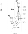
- FIG. 4 illustrates a vehicle 400 having the system 110 in an exemplary lane change scenario.
- the vehicle 400 is shown at different instances in time, T1 and T2, where T1 occurs prior in time to T2. Throughout instances T1 and T2, the vehicle 400 is shown traveling generally in the "X" direction as indicated.
- cruise control is set to a desired speed based on input from the driver, after which the ACC system maintains the desired speed by adjusting the acceleration of the vehicle.
- the controller 180 is continuously monitoring the vehicle's 400 acceleration, yaw rate, steering direction, and predicted path based on information received by the controller 180. This means that while in cruise control mode, the vehicle 400 is continuously applying the logic of FIG. 3 via the controller 180.
- the vehicle 400 is shown entering a lane change to avoid a moving vehicle 403.
- the system 110 for the vehicle 400 has a predicted vehicle path that is shown in FIG. 4 as being centered on a predicted trajectory 410 and bounded by the dotted lines 415a and 415b.
- the predicted vehicle path is calculated based on the vehicle's 400 sensed yaw rate and steering direction.
- the predicted trajectory 410 dictates the overall "shape" of the predicted vehicle path, depending on the yaw rate and steering direction of the vehicle 400.
- the boundaries 415a and 415b vary with the predicted trajectory 410, and define the width of the predicted vehicle path.
- the width of the predicted vehicle path (the area bounded between the lines 415a and 415b) is at least the width of the vehicle 400 itself or slightly wider, and is variable depending on the steering direction of the vehicle 400.
- the controller 180 continuously applies the logic of FIG. 3 .
- the change in steering direction is detected by the steering sensor 150 at block 301.
- the controller 180 then calculates the predicted path of the vehicle 400 at block 303, based on the sensed change in steering direction and the sensed yaw rate. This calculated vehicle path can be seen represented in FIG. 4 by the predicted trajectory 410 and the boundaries 415a and 415b.
- the predicted trajectory 410 at time T1 is shown curving toward the left, since, based on the yaw rate of the vehicle 400, the controller 180 calculates (or anticipates) the vehicle 400 to turn back into the left lane. This is because the predicted trajectory 410 sways back and forth with a curvature based on the sensed yaw rate for the vehicle 400, until the sensed yaw rate indicates that the vehicle 400 has straightened out, at which point the predicted trajectory 410 becomes straight.
- the left boundary 415a of the predicted path has a curvature calculated in accordance with the curvature of the predicted trajectory 410.
- the predicted vehicle path must be widened to also encompass objects present on the right lane (i.e., the lane that the vehicle 400 is switching into).
- the controller 180 calculates a lesser curvature for the right boundary 415b than for the left boundary 415a and the predicted trajectory 410.
- the predicted vehicle path is widened to encompass an area that includes the lane into which the vehicle 400 is turning. The widening of the predicted path can be triggered by the detected change in steering direction.
- the curvature of the boundary 415b could be calculated, for example, based on the vehicle heading or yaw rate in the last 3-4 seconds of the vehicle's 400 previously traveled course. This information is received by the controller 180 from the yaw rate sensor 140 in block 301 of FIG. 3 , and then stored to the memory module 220 to be recalled by the processor in calculating the predicted path in block 303. This is provided that a change in steering direction is detected.
- the boundary that a lesser curvature should be calculated for should be the boundary on the side closest to the lane that the vehicle 400 is switching into. Thus, in the case of the vehicle 400, which is switching into the right lane, the lesser curvature is calculated for the right boundary 415b.
- the predicted vehicle path can be widened to one side by the vehicle heading in the last 3-4 seconds of the vehicle's 400 previously traveled course.
- widening the course prediction is necessary because the yaw rate-based predicted trajectory 410 sways back and forth during a lane change (as seen for the predicted trajectory 410 and boundaries 415a and 415b at time T1 in FIG. 4 ).
- the predicted trajectory 410 is pointing away from the intended path of the vehicle 400.
- the predicted vehicle path encompasses an area ahead of the vehicle that is at least as wide as (or slightly wider than) the vehicle 400 itself, and is as far ahead of the vehicle 400 as a predetermined distance or range of distances (i.e., an established "look-ahead" distance).
- Calculating the predicted path in block 303 thus includes calculating the look-ahead distance, or the distance ahead of the vehicle 400 up to which the boundaries 415a and 415b extend. Therefore, beyond the look-ahead distance, any objects detected by the object sensor 160 at block 301 will not be selected at block 307. This is because the objects detected are not considered to be present within the boundaries of the predicted path.
- the look-ahead distance is visualized as extending as far as the dotted lines of 415a and 415b.
- no objects are selected for the vehicle 400 because no objects are detected by the object sensor 160 and selected within the predicted path.
- the vehicle 400 is still in cruise control and has straightened out into the right lane.
- the vehicle 400 approaches a stationary vehicle 417 that is already present in the right lane.
- the system 110 for the vehicle 400 has executed logic blocks 301-303, which means that the controller 180 has received the vehicle's 400 driving parameters from the parameter sensors, calculated the predicted path, and projected the predicted path.
- Receiving the vehicle's 400 driving parameters from the parameter sensors at time T2 means that the controller 180 has received a signal from the object sensor 160 that the stationary vehicle 417 is present ahead of the vehicle 400.
- the predicted trajectory 420 has straightened out, as have the path boundaries 425a and 425b. This is because the sensed yaw rate and steering direction at time T2 indicates that the vehicle 400 has straightened out. Thus, at time T2, no path widening is required, since no turns or lane changes have been detected.
- the boundaries 425a and 425b "intercept" the stationary vehicle 417. In other words, the stationary vehicle 417 comes into view of the predicted path, and thus within the boundaries 425a and 425b for the vehicle 400.
- the controller 180 executes block 307, the controller 180 selects the stationary vehicle 417 as an object to react on, which causes the logic of the controller 180 to proceed to block 311. This is because the stationary vehicle 417 is both detected by the object sensor 160, and is found within the boundaries 425a and 425b of the predicted path.
- the controller 180 compares the sensed acceleration of the vehicle 400 to the predefined threshold value, a T .
- the controller logic proceeds to block 313, and the controller 180 signals the engine control system 120 to freeze the vehicle 400's acceleration. This prevents the acceleration from increasing any further as the vehicle 400 approaches the stationary vehicle 417.
- deceleration or braking by the driver is allowed, the acceleration cannot be increased beyond the current value or a T . This limitation of the acceleration will persist for the vehicle 400 until the stationary vehicle 417 is no longer selected in the predicted path. For example, the driver may initiate another lane change into the left lane to avoid the stationary vehicle 417.
- the system 110 permits acceleration up to the value of a T , but no further, as described above with regard to FIG. 3 .
- the controller 180 executes blocks 301-307 and the stationary vehicle 417 is no longer selected in the predicted path, the control logic continues to block 309.
- the system 110 unfreezes the acceleration. At this point, the system 110 can once again resume either the previously-desired acceleration, or a new acceleration as dictated by the driver.
- the engine control system 220 will allow the vehicle 400 to continue at the acceleration it had prior to the controller's 180 reaction on the vehicle 417.
- the system 110 makes the reaction to the selected objects as smooth as possible.
- the system 110 does not give the feeling that it is reacting to the selected objects, whether the selected object is stationary or moving.
- freezing the current desired acceleration at a maximum acceleration based on the predefined threshold value a T does not generate a jerk from reducing the acceleration.
- the "worst case" feeling to the driver may be a lack of acceleration (i.e., in the event that an incorrect object is selected and reacted on). Since this worst case is very mild, a large number of incorrect detections are acceptable without distressing the driver.
- FIG. 5 diagrammatically illustrates a vehicle 500 having the system 110 in an exemplary turn or "curve in the road" scenario.
- the vehicle 500 is shown traveling generally in the "X" direction and is approaching a stationary vehicle 503, ahead.
- the vehicle 500 enters a curve in the road, which may also be perceived as a turn, and is continuously applying the logic blocks of FIG. 3 while in cruise control mode.
- the controller 180 receives driving parameters for the vehicle 500 from the parameter sensors. Among the driving parameters received are the yaw rate from the yaw rate sensor 140 and the steering direction from the steering sensor 150. Because the vehicle 500 is entering a turn due to the curve in the road, a change in steering direction is detected at block 301. Thus, at block 303, the controller 180 calculates a widened predicted path as described for the lane change scenario at time T1 in FIG. 4 . In calculating the predicted path, the controller 180 also incorporates the look-ahead distance, the possible methods for which are the same as those described with regard to FIG. 4 . Similarly (with regard to the case illustrated in FIG.
- the predicted trajectory 510 is calculated based on the current yaw rate of the vehicle 500, which causes the controller 180 to overestimate the turn. Overestimating the turn causes the predicted trajectory 510 to sway off the road and away from the intended vehicle path. Due to the detected change in steering direction, however, a widened predicted path is calculated and projected for the vehicle 500.
- the method for calculating the predicted path in the present turn scenario is the same as that used in the lane change scenario. Since the vehicle 500 is in a curve, it will eventually need to exit the curve, and the outer boundary of the course prediction is used to prepare for the vehicle 500 steering out of the curve (e.g., by using a lesser curvature or curvature change for that boundary).
- the boundary 515a is shown to have a lesser curvature than 515b on the right, which approximately follows the curve of the predicted trajectory 510.
- the boundary that a lesser curvature should be calculated for can be determined as the boundary that is on the outer side of the turn (i.e., the boundary on the side opposite the direction in which the vehicle is turning). For example, since the vehicle 500 is turning toward the right (i.e., clockwise), a lesser curvature is calculated and projected for the left-side boundary, 515a.
- the controller 180 determines whether or not to select the stationary vehicle 503 as an object to be reacted on. Because the stationary vehicle 503 has been detected by the object sensor 160 and is present within the predicted path boundaries 515a and 515b, the controller 180 selects the stationary vehicle 503, causing the control logic to proceed to block 311. The procedure for reacting on the stationary vehicle 503 is the same as for reacting on the stationary vehicle 417 in FIG. 4 .
- the control logic proceeds to block 313 and freezes the acceleration until the stationary vehicle 513 is no longer selected. After the stationary vehicle 513 is no longer selected, the system 110 resumes normal ACC functions. If the acceleration is less than a T , the value of a T is set as the maximum value that the acceleration can achieve until the stationary vehicle 503 is no longer selected.
- embodiments of the invention relate to systems and methods for controlling an ACC system.
- embodiments of the invention relate to methods for an ACC to identify objects in a path of a vehicle and limit an acceleration of the vehicle when the acceleration is above a threshold and an object is identified.
- Embodiments of the invention are not limited to the exemplary scenarios described herein, and are therefore applicable to a plurality of different scenarios and arrangements of hardware or software-based devices.
- the thresholds, values, and parameters described are all subject to tuning.
- different shapes for the predicted path including the predicted trajectories and boundaries, may also be used.
- This method may also be applied to any vehicle, regardless of whether they are moving, driving in the same direction, or oncoming.
- This method may also be used in systems that generally react to stationary objects, or implemented as an initial partial reaction (i.e., limiting the acceleration without braking) prior to an additional full reaction taking place (i.e., a full brake administered by the ACC system).
Description
- Embodiments of the present invention relate to an adaptive cruise control (ACC), specifically to an ACC that reacts to stationary objects.
- Prior art ACC systems do not accurately identify stationary objects, and are thus unable to react to stationary objects that the host vehicle encounters in the driving path, including parked cars. This is because radar sensors are commonly used in adaptive cruise control systems, which cannot accurately distinguish between vehicles and infrastructure such as poles, signs, or bridges. ACC systems that are unable to react to stationary objects within the host vehicle path also cannot detect objects such as stopped cars; i.e., in a traffic light scenario where the host vehicle switches into a lane already occupied by another vehicle waiting at the intersection. In this case, not only will the ACC system not react to the object, but the system might accelerate toward the object with a magnitude dependent on the speed the ACC system is trying to achieve, which could be high. The higher the acceleration commanded by the ACC system toward the stationary object, the more uncomfortable the effect can feel to the driver.
The following prior art documents describe some technological background for the present invention: - D1:
US 2001/027371 A1 - D2:
EP2405 416 A1 - D3:
US 2009/248270 A1 - Although video sensors can distinguish between vehicles and infrastructure better than radar sensors, they exhibit weaknesses in estimating longitudinal velocities and accelerations. Therefore, future implementations may include a combined video and radar sensor approach to stationary object detection. However, the added sensors for a combined video and radar approach require additional hardware, thus increasing me cost of the system.
For this reason, ACC systems that do not react on stationary objects will remain common for some time. - In one embodiment, the invention provides a method for identifying stationary objects in a path of a vehicle and limiting an acceleration of the vehicle when the acceleration is above a threshold and a stationary object is identified.
- In another embodiment, the invention provides an ACC system for a vehicle. The ACC system includes a vehicle parameter sensor, an object detection sensor, and a controller. The controller is configured to calculate the vehicle's path based on a signal from the parameter sensor, detect an object based on the vehicle's path and a signal from the object detection sensor, determine an acceleration of the vehicle, and prevent the acceleration of the vehicle from increasing while the object is detected and the acceleration of the vehicle is greater than a predetermined acceleration threshold.
- Other aspects of the invention will become apparent by consideration of the detailed description and accompanying drawings.
-
-
FIG. 1 schematically illustrates an ACC system. -
FIG. 2 schematically illustrates a controller included in the ACC system ofFIG. 1 . -
FIG. 3 is a flowchart illustrating control logic of the ACC system ofFIG. 1 . -
FIG. 4 diagrammatically illustrates a vehicle having the system ofFIG. 1 in a lane change scenario. -
FIG. 5 diagrammatically illustrates a vehicle having the system ofFIG. 1 in a turn or "curve in the road" scenario. - Before any embodiments of the invention are explained in detail, it is to be understood that the invention is not limited in its application to the details of construction and the arrangement of components set forth in the following description or illustrated in the following drawings. The invention is capable of other embodiments and of being practiced or of being carried out in various ways.
- Also, it is to be understood that the phraseology and terminology used herein is for the purpose of description and should not be regarded as limiting. The use of "including," "comprising" or "having" and variations thereof herein is meant to encompass the items listed thereafter and equivalents thereof as well as additional items. The terms "mounted," "connected" and "coupled" are used broadly and encompass both direct and indirect mounting, connecting and coupling. Further, "connected" and "coupled" are not restricted to physical or mechanical connections or couplings, and can include electrical connections or couplings, whether direct or indirect. Also, electronic communications and notifications may be performed using any known means including direct connections, wireless connections, etc.
- It should be noted that a plurality of hardware and software based devices, as well as a plurality of different structural components may be utilized to implement the invention. Furthermore, and as described in subsequent paragraphs, the specific configurations illustrated in the drawings are intended to exemplify embodiments of the invention and that other alternative configurations are possible.
- The invention enables a partial reaction to stationary objects by an ACC using radar sensors that reduces the uncomfortable feeling of accelerating quickly toward stationary objects. The general idea is to detect stationary objects ahead of the vehicle, and then to limit acceleration without giving the driver the feeling that the ACC system is reacting on the stationary vehicle.
-
FIG. 1 illustrates avehicle 100 having anACC system 110. Thevehicle 100 also has an engine control system 120. The Engine control system 120 may include known components or systems for adjusting the acceleration of thevehicle 100, such as a vehicle accelerator or an engine timing controller. TheACC system 110 has avehicle acceleration sensor 130 for detecting the longitudinal acceleration of thevehicle 100, ayaw rate sensor 140 for detecting the rate at which thevehicle 100 is turning about its yaw axis, and a steering sensor 150 for detecting changes in steering direction of thevehicle 100. TheACC system 110 also has an object sensor 160 for detecting objects in the vicinity of thevehicle 100. The object sensor 160 may include any suitable object detecting sensors, such as a radar sensor or a video sensor. The object sensor 160 may also be used alone or in combination with other sensors. TheACC system 110 also includes a controller 180 (or electronic control unit, "ECU") that communicates electronically withsensors communication bus 190. Thecontroller 180 is also in electronic communication with the engine control system 120 over thebus 190. It should be noted thatbus 190 encompasses both wired and wireless forms of connection or data communication, and that one or more sensors can communicate with thecontroller 180 via a direct connection. - The
controller 180 may be a microprocessor-based controller such as a computer.FIG. 2 illustrates thecontroller 180. Thecontroller 180 includes a processing unit 210 (e.g., a microprocessor, an application specific integrated circuit ("ASIC"), etc.), one ormore memory modules 220, and an input/output interface 230. Thememory modules 220 include non-transitory computer-readable media, such as random-access memory ("RAM") and/or read-only memory ("ROM"). Theprocessing unit 210 can retrieve instructions from thememory modules 220 and execute the instructions to perform particular functionality. Theprocessing unit 210 can also retrieve and store data to the memory modules as part of executing the instructions. - In addition, the
processing unit 210 can obtain data from devices and systems external to thecontroller 180 through the input/output interface 230. For example, as noted above, thecontroller 180 is in electronic communication with thesensors controller 180 also provides output to the engine control system 120. Therefore, the input/output interface 230 connects thecontroller 180 to thesensors communication line 190, as mentioned above with regard toFIG. 1 . - It should also be understood that the
controller 180 can include additional components other than those described herein. Furthermore, in some embodiments, the functionality of thecontroller 180 can be distributed among multiple systems or devices. Also, in some embodiments, the functionality of thecontroller 180 can be combined with other systems or devices. For example, in some embodiments, thecontroller 180 may also perform in part the functionality of the engine control system 120. -
Controller 180 contains logic that is executed by theprocessing unit 210. This logic, among other functions, limits vehicle acceleration based on detected stationary objects. For example,FIG. 3 shows the logic employed by thesystem 110 while thevehicle 100 is in cruise control mode. In ACC systems, cruise control mode makes it possible for a vehicle to follow a directly preceding vehicle (i.e., "object") at a certain distance or time gap without direct control from the driver to the vehicle controls (e.g., via the brake or acceleration pedals). In regions of light traffic or where no objects are present, the driver may use the ACC system such that speed regulation takes place at a desired, or "setpoint", speed. In order to maintain the desired speed as selected by the driver, the ACC system adjusts the vehicle acceleration whenever the vehicle drifts from the desired speed. The acceleration demanded by the ACC system to maintain the vehicle speed is herein referred to as the "desired acceleration", which is also the acceleration sensed by theacceleration sensor 130 while thesystem 110 is in cruise control mode. - At
block 301 inFIG. 3 , thecontroller 180 receives the vehicle's 100 driving parameters from theacceleration sensor 130, theyaw rate sensor 140, the steering sensor 150, and the object sensor 160; herein referred to collectively as "parameter sensors." The sensed driving parameters may include a longitudinal acceleration of the vehicle from theacceleration sensor 130, a vehicle yaw rate from theyaw rate sensor 140, a change in steering direction or steering angle from the steering sensor 150, and one or more detected object indications from the object sensor 160. Atblock 303, thecontroller 180 uses the sensed driving parameters, particularly the sensed vehicle yaw rate and the sensed steering direction, to calculate a predicted vehicle path. The predicted vehicle path has boundaries that are determined based on the sensed yaw rate of thevehicle 100 as well as the width of thevehicle 100. The predicted vehicle path encompasses an area ahead of the vehicle that is at least as wide as (or slightly wider than) thevehicle 100 itself, and is as far ahead of thevehicle 100 as a predetermined distance or range of distances (i.e., an established "look-ahead" distance). As described in further detail below, the predicted vehicle path boundaries are variable based on the sensed steering direction of thevehicle 100. In particular, the predicted path width is varied depending on the sensed yaw rate, a change in magnitude of steering direction, and/or a vehicle heading. The driving parameters received by thecontroller 180 may be stored to thememory module 220 to be accessed by theprocessor 210 as the logic ofFIG. 3 is executed. For each predicted vehicle path calculation, the driving parameters in thememory module 220 are updated. - At
block 307, thecontroller 180 uses the predicted vehicle path and the sensed object detection data to select objects to react to. An object is selected if it is both sensed by the object sensor 160 and determined to be present within the boundaries of the predicted vehicle path. If no objects are selected atblock 307, the logic of thecontroller 180 proceeds to block 309, such that thesystem 110 unfreezes the vehicle's 100 acceleration if necessary (as will be described below in further detail), and thecontroller 180 proceeds to block 301. However, if an object is selected atblock 307, thecontroller 180 proceeds to block 311. - At
block 311, the sensed acceleration ofvehicle 100 is compared to a predetermined acceleration threshold value ("aT "). The value of aT is positive (e.g., approximately 0.5 m/s2). This means that some acceleration can always be achieved, guaranteeing some acceleration even when an incorrect object is selected in the predicted path. If the desired acceleration is greater than or equal to aT , thecontroller 180 proceeds to block 313, where thecontroller 180 signals the engine control system 120 to freeze the acceleration of thevehicle 100. Although freezing the acceleration prevents the acceleration from increasing any further, deceleration or braking by the ACC system is still permitted. After freezing the acceleration, thecontroller 180 returns to block 301 and repeats the object detection functionality described above. If an object is no longer selected within the predicted path atblock 307, thecontroller 180 signals the engine control system 120 to unfreeze the acceleration atblock 309, and theACC system 110 resumes normal cruise control functions. - If the desired acceleration at
block 311 is determined to be less than aT, however, thecontroller 180 returns directly to block 301 to repeat the logic steps of blocks 301-311. In this case, since the acceleration is determined to be less than aT, thesystem 110 does not freeze the acceleration. However, atblock 307, if an object is still in the vehicle path, thecontroller 180 will permit increases in acceleration up to the value of aT, but no further than aT, until the object is no longer selected in the predicted vehicle path. - In blocks 301-311 of
FIG. 3 , thecontroller 180 repeatedly monitors the vehicle's 100 acceleration, yaw rate, steering direction, and predicted path based on information received by thecontroller 180. The logic ofFIG. 3 will be used to describe the scenario ofFIG. 4 , below. However, the logic presented is not limited strictly to the exemplary scenarios discussed herein. The logic presented inFIG. 3 can be widely implemented in a plurality of other hardware or software based devices, and therefore in a plurality of different scenarios, as well. -
FIG. 4 illustrates avehicle 400 having thesystem 110 in an exemplary lane change scenario. Thevehicle 400 is shown at different instances in time, T1 and T2, where T1 occurs prior in time to T2. Throughout instances T1 and T2, thevehicle 400 is shown traveling generally in the "X" direction as indicated. Also, prior to T1, cruise control is set to a desired speed based on input from the driver, after which the ACC system maintains the desired speed by adjusting the acceleration of the vehicle. While thevehicle 400 is in cruise control mode, thecontroller 180 is continuously monitoring the vehicle's 400 acceleration, yaw rate, steering direction, and predicted path based on information received by thecontroller 180. This means that while in cruise control mode, thevehicle 400 is continuously applying the logic ofFIG. 3 via thecontroller 180. - At T1 in
FIG. 4 , thevehicle 400 is shown entering a lane change to avoid a movingvehicle 403. Thesystem 110 for thevehicle 400 has a predicted vehicle path that is shown inFIG. 4 as being centered on a predictedtrajectory 410 and bounded by the dottedlines 415a and 415b. As described above, the predicted vehicle path is calculated based on the vehicle's 400 sensed yaw rate and steering direction. The predictedtrajectory 410 dictates the overall "shape" of the predicted vehicle path, depending on the yaw rate and steering direction of thevehicle 400. Theboundaries 415a and 415b vary with the predictedtrajectory 410, and define the width of the predicted vehicle path. As previously explained, the width of the predicted vehicle path (the area bounded between thelines 415a and 415b) is at least the width of thevehicle 400 itself or slightly wider, and is variable depending on the steering direction of thevehicle 400. - As previously mentioned, while the
vehicle 400 is in cruise control mode, thecontroller 180 continuously applies the logic ofFIG. 3 . When thevehicle 400 initiates a lane change by steering toward the right lane, the change in steering direction is detected by the steering sensor 150 atblock 301. Thecontroller 180 then calculates the predicted path of thevehicle 400 atblock 303, based on the sensed change in steering direction and the sensed yaw rate. This calculated vehicle path can be seen represented inFIG. 4 by the predictedtrajectory 410 and theboundaries 415a and 415b. - In
FIG. 4 , the predictedtrajectory 410 at time T1 is shown curving toward the left, since, based on the yaw rate of thevehicle 400, thecontroller 180 calculates (or anticipates) thevehicle 400 to turn back into the left lane. This is because the predictedtrajectory 410 sways back and forth with a curvature based on the sensed yaw rate for thevehicle 400, until the sensed yaw rate indicates that thevehicle 400 has straightened out, at which point the predictedtrajectory 410 becomes straight. Theleft boundary 415a of the predicted path has a curvature calculated in accordance with the curvature of the predictedtrajectory 410. However, since thevehicle 400 is switching into the right lane and not turning back into the left lane as anticipated by thecontroller 180, the predicted vehicle path must be widened to also encompass objects present on the right lane (i.e., the lane that thevehicle 400 is switching into). In one embodiment, to widen the predicted path of thevehicle 400, thecontroller 180 calculates a lesser curvature for the right boundary 415b than for theleft boundary 415a and the predictedtrajectory 410. By applying a lesser curvature to the right boundary 415b, the predicted vehicle path is widened to encompass an area that includes the lane into which thevehicle 400 is turning. The widening of the predicted path can be triggered by the detected change in steering direction. A change in steering direction could mean, for example, that the steering wheel is sensed to be rotated away from the center (or "equilibrium") position that would otherwise maintain the vehicle on a straight-line path. The direction in which the vehicle is sensed to be steering indicates the side to which the predicted path is widened (i.e., will indicate which boundary will have a lesser calculated curvature). - The curvature of the boundary 415b could be calculated, for example, based on the vehicle heading or yaw rate in the last 3-4 seconds of the vehicle's 400 previously traveled course. This information is received by the
controller 180 from theyaw rate sensor 140 inblock 301 ofFIG. 3 , and then stored to thememory module 220 to be recalled by the processor in calculating the predicted path inblock 303. This is provided that a change in steering direction is detected. The boundary that a lesser curvature should be calculated for should be the boundary on the side closest to the lane that thevehicle 400 is switching into. Thus, in the case of thevehicle 400, which is switching into the right lane, the lesser curvature is calculated for the right boundary 415b. In this way, for lane changes or similar cases such as turns, the predicted vehicle path can be widened to one side by the vehicle heading in the last 3-4 seconds of the vehicle's 400 previously traveled course. As described above, widening the course prediction is necessary because the yaw rate-based predictedtrajectory 410 sways back and forth during a lane change (as seen for the predictedtrajectory 410 andboundaries 415a and 415b at time T1 inFIG. 4 ). Particularly, prior to finally straightening thevehicle 400 out after a lane change, the predictedtrajectory 410 is pointing away from the intended path of thevehicle 400. By calculating a widened predicted path, an object (e.g., a stationary vehicle) in the lane that thevehicle 400 is switching into can be selected earlier. - As previously described, the predicted vehicle path encompasses an area ahead of the vehicle that is at least as wide as (or slightly wider than) the
vehicle 400 itself, and is as far ahead of thevehicle 400 as a predetermined distance or range of distances (i.e., an established "look-ahead" distance). Calculating the predicted path inblock 303 thus includes calculating the look-ahead distance, or the distance ahead of thevehicle 400 up to which theboundaries 415a and 415b extend. Therefore, beyond the look-ahead distance, any objects detected by the object sensor 160 atblock 301 will not be selected atblock 307. This is because the objects detected are not considered to be present within the boundaries of the predicted path. InFIG. 4 , for example, the look-ahead distance is visualized as extending as far as the dotted lines of 415a and 415b. - Defining the look-ahead distance to react to a stationary object sets the longitudinal boundaries of the predicted path. Any objects detected within the predicted path (i.e., within the area bounded by the
boundaries 415a and 415b, as well as within the look-ahead distance) are selected by thecontroller 180 as objects to react on. In one embodiment, the look-ahead distance is not limited to being a fixed distance, but could also include a range of distances that are, for example, variable based on the vehicle's 400 speed. Many different criteria or combinations of criteria can be used to define the look-ahead distance. For example, a time to collision less than a threshold (e.g., approximately 4 seconds) could be used to identify a stationary object to react to. In addition, a minimum distance to the stationary object could be incorporated. Alternatively, the distance to be covered, assuming a given deceleration, can be used to identify the stationary object. And, a maximum distance can also be defined in order to avoid incorrect acquisitions at high speeds. - At time T1 in
FIG. 4 , no objects are selected for thevehicle 400 because no objects are detected by the object sensor 160 and selected within the predicted path. However, at time T2 inFIG. 4 . thevehicle 400 is still in cruise control and has straightened out into the right lane. At this time, thevehicle 400 approaches astationary vehicle 417 that is already present in the right lane. At this time, thesystem 110 for thevehicle 400 has executed logic blocks 301-303, which means that thecontroller 180 has received the vehicle's 400 driving parameters from the parameter sensors, calculated the predicted path, and projected the predicted path. Receiving the vehicle's 400 driving parameters from the parameter sensors at time T2 means that thecontroller 180 has received a signal from the object sensor 160 that thestationary vehicle 417 is present ahead of thevehicle 400. Also at time T2, the predictedtrajectory 420 has straightened out, as have the path boundaries 425a and 425b. This is because the sensed yaw rate and steering direction at time T2 indicates that thevehicle 400 has straightened out. Thus, at time T2, no path widening is required, since no turns or lane changes have been detected. As thevehicle 400 at T2 approaches thestationary vehicle 417, the boundaries 425a and 425b "intercept" thestationary vehicle 417. In other words, thestationary vehicle 417 comes into view of the predicted path, and thus within the boundaries 425a and 425b for thevehicle 400. Thus, when thecontroller 180 executesblock 307, thecontroller 180 selects thestationary vehicle 417 as an object to react on, which causes the logic of thecontroller 180 to proceed to block 311. This is because thestationary vehicle 417 is both detected by the object sensor 160, and is found within the boundaries 425a and 425b of the predicted path. - As previously described, at
block 311, thecontroller 180 compares the sensed acceleration of thevehicle 400 to the predefined threshold value, aT . At time T2, if the sensed acceleration (i.e., the acceleration desired by the system 110) is greater than or equal to aT, and an object is selected (i.e., the stationary vehicle 417), the controller logic proceeds to block 313, and thecontroller 180 signals the engine control system 120 to freeze thevehicle 400's acceleration. This prevents the acceleration from increasing any further as thevehicle 400 approaches thestationary vehicle 417. Although deceleration or braking by the driver is allowed, the acceleration cannot be increased beyond the current value or aT . This limitation of the acceleration will persist for thevehicle 400 until thestationary vehicle 417 is no longer selected in the predicted path. For example, the driver may initiate another lane change into the left lane to avoid thestationary vehicle 417. - However, at time T2, if the sensed acceleration of the
vehicle 400 is determined to be less than aT, then thesystem 110 permits acceleration up to the value of aT, but no further, as described above with regard toFIG. 3 . When thecontroller 180 executes blocks 301-307 and thestationary vehicle 417 is no longer selected in the predicted path, the control logic continues to block 309. Atblock 309, thesystem 110 unfreezes the acceleration. At this point, thesystem 110 can once again resume either the previously-desired acceleration, or a new acceleration as dictated by the driver. If the driver does not select a new acceleration (i.e., after decelerating or braking in response to the system's 110 reaction on the stationary vehicle 417), theengine control system 220 will allow thevehicle 400 to continue at the acceleration it had prior to the controller's 180 reaction on thevehicle 417. - Accordingly, the
system 110 makes the reaction to the selected objects as smooth as possible. In particular, thesystem 110 does not give the feeling that it is reacting to the selected objects, whether the selected object is stationary or moving. In addition, by using a wide course prediction and large look-ahead distance, there is a high chance of selecting non-vehicle radar reflections off posts, bridges, manhole covers, etc. Furthermore, freezing the current desired acceleration at a maximum acceleration based on the predefined threshold value aT , as described above, does not generate a jerk from reducing the acceleration. With the implementation of the methods described herein, the "worst case" feeling to the driver may be a lack of acceleration (i.e., in the event that an incorrect object is selected and reacted on). Since this worst case is very mild, a large number of incorrect detections are acceptable without distressing the driver. - As previously mentioned, the logic presented in
FIG. 3 can be widely implemented in a plurality of diverse scenarios, and is not limited to those scenarios discussed herein. For example,FIG. 5 diagrammatically illustrates avehicle 500 having thesystem 110 in an exemplary turn or "curve in the road" scenario. As with the lane-change scenario diagrammed inFIG. 4 at time T2, thevehicle 500 is shown traveling generally in the "X" direction and is approaching astationary vehicle 503, ahead. In the scenario ofFIG. 5 , thevehicle 500 enters a curve in the road, which may also be perceived as a turn, and is continuously applying the logic blocks ofFIG. 3 while in cruise control mode. - At
block 301, thecontroller 180 receives driving parameters for thevehicle 500 from the parameter sensors. Among the driving parameters received are the yaw rate from theyaw rate sensor 140 and the steering direction from the steering sensor 150. Because thevehicle 500 is entering a turn due to the curve in the road, a change in steering direction is detected atblock 301. Thus, atblock 303, thecontroller 180 calculates a widened predicted path as described for the lane change scenario at time T1 inFIG. 4 . In calculating the predicted path, thecontroller 180 also incorporates the look-ahead distance, the possible methods for which are the same as those described with regard toFIG. 4 . Similarly (with regard to the case illustrated inFIG. 4 ), the predictedtrajectory 510 is calculated based on the current yaw rate of thevehicle 500, which causes thecontroller 180 to overestimate the turn. Overestimating the turn causes the predictedtrajectory 510 to sway off the road and away from the intended vehicle path. Due to the detected change in steering direction, however, a widened predicted path is calculated and projected for thevehicle 500. The method for calculating the predicted path in the present turn scenario is the same as that used in the lane change scenario. Since thevehicle 500 is in a curve, it will eventually need to exit the curve, and the outer boundary of the course prediction is used to prepare for thevehicle 500 steering out of the curve (e.g., by using a lesser curvature or curvature change for that boundary). - In
FIG. 5 , the boundary 515a is shown to have a lesser curvature than 515b on the right, which approximately follows the curve of the predictedtrajectory 510. In the case for turns, such as described for thevehicle 500, the boundary that a lesser curvature should be calculated for can be determined as the boundary that is on the outer side of the turn (i.e., the boundary on the side opposite the direction in which the vehicle is turning). For example, since thevehicle 500 is turning toward the right (i.e., clockwise), a lesser curvature is calculated and projected for the left-side boundary, 515a. - Among the parameters received by the
controller 180 atblock 301 is an indication from the object sensor 160 that thestationary vehicle 503 lias been detected ahead. Atblock 307, thecontroller 180 determines whether or not to select thestationary vehicle 503 as an object to be reacted on. Because thestationary vehicle 503 has been detected by the object sensor 160 and is present within the predicted path boundaries 515a and 515b, thecontroller 180 selects thestationary vehicle 503, causing the control logic to proceed to block 311. The procedure for reacting on thestationary vehicle 503 is the same as for reacting on thestationary vehicle 417 inFIG. 4 . Atblock 311, if the sensed acceleration is greater than or equal to aT, the control logic proceeds to block 313 and freezes the acceleration until the stationary vehicle 513 is no longer selected. After the stationary vehicle 513 is no longer selected, thesystem 110 resumes normal ACC functions. If the acceleration is less than aT , the value of aT is set as the maximum value that the acceleration can achieve until thestationary vehicle 503 is no longer selected. - Thus, embodiments of the invention relate to systems and methods for controlling an ACC system. Particularly, embodiments of the invention relate to methods for an ACC to identify objects in a path of a vehicle and limit an acceleration of the vehicle when the acceleration is above a threshold and an object is identified. Embodiments of the invention are not limited to the exemplary scenarios described herein, and are therefore applicable to a plurality of different scenarios and arrangements of hardware or software-based devices. It should also be noted that the thresholds, values, and parameters described are all subject to tuning. Furthermore, different shapes for the predicted path, including the predicted trajectories and boundaries, may also be used. This method may also be applied to any vehicle, regardless of whether they are moving, driving in the same direction, or oncoming. This method may also be used in systems that generally react to stationary objects, or implemented as an initial partial reaction (i.e., limiting the acceleration without braking) prior to an additional full reaction taking place (i.e., a full brake administered by the ACC system).
- Various features of the invention are set forth in the following claims.
Claims (15)
- A method for controlling a vehicle (100, 400), the method comprising:a) predicting (301, 303) the vehicle's path (410; 415a, 415b); andb) detecting (160) a stationary object (417) within the predicted path;characterized byc) determining (311) that an acceleration of the vehicle is greater than a predetermined acceleration threshold (aT); and,d) maintaining (313) the acceleration.
- The method according t0 claim 1, wherein predicting the vehicle's path includes
predicting a vehicle trajectory based on a vehicle yaw rate and
generating a path width (415a, 415b) based on the predicted vehicle trajectory and a width of the vehicle. - The method according to claim 2, wherein generating a path width includes
detecting a change in direction, and
increasing the path width based on a magnitude of the change in direction. - The method according to claim 3, wherein the change in direction is detected by a steering direction sensor (150).
- The method according to claim 1, wherein detecting a stationary object includes detecting objects within the predicted path that are within a pre-determined distance ahead of the vehicle, the predetermined distance based on one selected from a group consisting of a pre-defined time-until-collision, a deceleration of the vehicle, and a pre-defined maximum distance.
- The method according to claim 1, further comprising, accelerating normally when the stationary object is no longer detected.
- An adaptive cruise control (ACC) system (110) for a vehicle (100, 400), the ACC system comprising:a) a vehicle parameter sensor (130, 140, 150);b) an object detection sensor (160); and,c) a controller (180) configured to:c1) calculate (303) the vehicle's path (410, 415a, 415b) based on a signal from the vehicle parameter sensor (130, 140, 150);c2) detect (307) a stationary object (417) based on the vehicle's path and a signal from the object detection sensor (160); andc3) determine (311) an acceleration of the vehicle;
characterized in thatc4) when the acceleration of the vehicle is determined (311) to be greater than a predetermined acceleration threshold (aT), the controller (160) is further adapted to maintain the acceleration of the vehicle. - The system of claim 7, wherein the object detection sensor includes a radar sensor.
- The system of claim 7, wherein the object detection sensor includes a video camera configured to capture images ahead of the vehicle.
- The system of claim 7, wherein the parameter sensor is at least one of a yaw rate sensor, an acceleration sensor, and a steering direction sensor.
- The system of claim 10, wherein the ACC includes a yaw rate sensor and a steering direction sensor, and the controller calculates the predicted path based on a yaw rate and a steering direction.
- The system of claim 11, wherein the vehicle's path further includes a vehicle trajectory based on the yaw rate and
a path width based on the vehicle trajectory and a width (415a, 415b) of the vehicle. - The system of claim 12, wherein the path width further includes
a detected change in direction, and
an increase in the path width based on a magnitude of the change in direction. - The system of claim 13, wherein the change in direction is a change in the steering direction.
- The system of claim 11, wherein the vehicle's path includes a pre-determined distance ahead of the vehicle, based on one selected from a group consisting of a pre-defined time-until-collision, a deceleration of the vehicle, and a pre-defined maximum distance.
Applications Claiming Priority (3)
| Application Number | Priority Date | Filing Date | Title |
|---|---|---|---|
| US201361821290P | 2013-05-09 | 2013-05-09 | |
| US14/065,539 US9085236B2 (en) | 2013-05-09 | 2013-10-29 | Adaptive cruise control with stationary object recognition |
| PCT/US2014/037066 WO2014182765A1 (en) | 2013-05-09 | 2014-05-07 | Adaptive cruise control with stationary object recognition |
Publications (2)
| Publication Number | Publication Date |
|---|---|
| EP2994359A1 EP2994359A1 (en) | 2016-03-16 |
| EP2994359B1 true EP2994359B1 (en) | 2019-01-02 |
Family
ID=51865389
Family Applications (1)
| Application Number | Title | Priority Date | Filing Date |
|---|---|---|---|
| EP14731855.4A Active EP2994359B1 (en) | 2013-05-09 | 2014-05-07 | Adaptive cruise control with stationary object recognition |
Country Status (4)
| Country | Link |
|---|---|
| US (1) | US9085236B2 (en) |
| EP (1) | EP2994359B1 (en) |
| CN (1) | CN105339228B (en) |
| WO (1) | WO2014182765A1 (en) |
Families Citing this family (15)
| Publication number | Priority date | Publication date | Assignee | Title |
|---|---|---|---|---|
| US10377376B2 (en) * | 2016-10-06 | 2019-08-13 | Ford Global Technologies, Llc | Vehicle with environmental context analysis |
| KR102039487B1 (en) * | 2016-11-11 | 2019-11-26 | 엘지전자 주식회사 | Vehicle driving control apparatus and method |
| CN108282512B (en) * | 2017-01-04 | 2022-06-24 | 本田技研工业株式会社 | System and method for vehicle control using vehicle communication |
| JP6809331B2 (en) * | 2017-03-28 | 2021-01-06 | トヨタ自動車株式会社 | Vehicle control device |
| CN109204311B (en) * | 2017-07-04 | 2021-06-01 | 华为技术有限公司 | Automobile speed control method and device |
| WO2019039105A1 (en) * | 2017-08-25 | 2019-02-28 | 日立オートモティブシステムズ株式会社 | Motion control device for moving body |
| JP6834853B2 (en) * | 2017-08-31 | 2021-02-24 | トヨタ自動車株式会社 | Vehicle control device |
| KR102463175B1 (en) | 2017-09-04 | 2022-11-04 | 삼성전자주식회사 | Method and apparatus of recognizing object |
| US10534071B2 (en) * | 2017-10-24 | 2020-01-14 | Robert Bosch Gmbh | Using data from a radar sensor for machine learning based perception |
| CN109733293A (en) * | 2018-12-14 | 2019-05-10 | 江苏辰汉电子科技有限公司 | A kind of novel on-vehicle intelligent end device for supporting speech recognition |
| DE102019130609A1 (en) * | 2019-11-13 | 2021-05-20 | Ford Global Technologies, Llc | Method for determining a controller for a controlled system |
| JP7226284B2 (en) * | 2019-12-06 | 2023-02-21 | トヨタ自動車株式会社 | Information processing device, information processing method, program |
| EP4131206A4 (en) * | 2020-03-25 | 2024-04-24 | Bosch Gmbh Robert | Vehicle-position identification system and vehicle-position identification device |
| CN113071489A (en) * | 2021-04-30 | 2021-07-06 | 宝能(广州)汽车研究院有限公司 | Vehicle running control method and device, vehicle-mounted electronic equipment and readable storage medium |
| US11912274B2 (en) * | 2021-05-04 | 2024-02-27 | Ford Global Technologies, Llc | Adaptive cruise control with non-visual confirmation of obstacles |
Family Cites Families (37)
| Publication number | Priority date | Publication date | Assignee | Title |
|---|---|---|---|---|
| US6223117B1 (en) * | 1997-05-27 | 2001-04-24 | General Motors Corporation | Cut-in management for an adaptive cruise control system |
| DE19757062A1 (en) | 1997-12-20 | 1999-06-24 | Bayerische Motoren Werke Ag | Distance-related, electronically controlled vehicle speed control system |
| DE19855400A1 (en) * | 1998-12-01 | 2000-06-15 | Bosch Gmbh Robert | Method and device for determining a future course range of a vehicle |
| EP1206710A1 (en) * | 1999-08-06 | 2002-05-22 | Roadrisk Technologies, Llc | Method and apparatus for stationary object detection |
| DE10015300B4 (en) | 2000-03-28 | 2018-04-05 | Robert Bosch Gmbh | Method and device for controlling the driving speed of a vehicle |
| JP2002005277A (en) * | 2000-06-22 | 2002-01-09 | Denso Corp | Vehicle control system |
| DE10149146A1 (en) * | 2001-10-05 | 2003-04-17 | Bosch Gmbh Robert | Speed regulator with distance regulating function for motor vehicle, has monitoring module for detecting situation with danger of objects not detected by location system being in immediate vicinity |
| JP3846366B2 (en) * | 2002-02-18 | 2006-11-15 | 日産自動車株式会社 | Travel speed control device |
| JP2003260957A (en) * | 2002-03-11 | 2003-09-16 | Hitachi Ltd | Inter-vehicle distance control system |
| DE10345802A1 (en) * | 2003-09-30 | 2005-04-14 | Robert Bosch Gmbh | Driving lane recognizing method e.g. for vehicle, involves equipping adaptive spacer and speed control which are governed by object detection system and detects relative velocity of objects |
| US7831367B2 (en) * | 2002-11-21 | 2010-11-09 | Lucas Automotive Gmbh | System for influencing the speed of a motor vehicle |
| DE10311192A1 (en) * | 2003-03-12 | 2004-09-23 | Robert Bosch Gmbh | Device and procedure for the speed control of e.g. motor vehicle, has speed governor measuring object for identified objects using radar |
| DE10330922A1 (en) | 2003-07-10 | 2005-02-10 | Daimlerchrysler Ag | Intelligent cruise and distance controller has feature to determine the relative distance to a preceding foreign object in the driving lane |
| DE602004016520D1 (en) * | 2003-07-11 | 2008-10-23 | Toyota Motor Co Ltd | IMPACT SAFETY VEHICLE CONTROL SYSTEM |
| DE10356309A1 (en) * | 2003-11-28 | 2005-06-23 | Robert Bosch Gmbh | Method and device for warning the driver of a motor vehicle |
| JP3987044B2 (en) | 2004-02-19 | 2007-10-03 | 本田技研工業株式会社 | Inter-vehicle distance control device |
| US7512475B2 (en) | 2004-03-19 | 2009-03-31 | Delphi Technologies, Inc. | Automatic lateral acceleration limiting and non threat target rejection |
| JP2006105598A (en) * | 2004-09-30 | 2006-04-20 | Honda Motor Co Ltd | Acceleration/angular velocity sensor unit |
| JP4451315B2 (en) | 2005-01-06 | 2010-04-14 | 富士重工業株式会社 | Vehicle driving support device |
| DE102005024716B4 (en) * | 2005-05-30 | 2023-09-21 | Robert Bosch Gmbh | Method and device for recognizing and classifying objects |
| US20070233353A1 (en) * | 2006-03-28 | 2007-10-04 | Alexander Kade | Enhanced adaptive cruise control system with forward vehicle collision mitigation |
| DE502006009038D1 (en) | 2006-05-03 | 2011-04-14 | Adc Automotive Dist Control | Method for controlling the speed of a vehicle in a complex traffic situation |
| JP4297132B2 (en) * | 2006-05-12 | 2009-07-15 | トヨタ自動車株式会社 | Vehicle alarm device |
| DE102007013685A1 (en) * | 2007-03-22 | 2008-09-25 | Robert Bosch Gmbh | Collision warning device for motor vehicles |
| JP2009220630A (en) | 2008-03-13 | 2009-10-01 | Fuji Heavy Ind Ltd | Traveling control device for vehicle |
| JP5180641B2 (en) | 2008-03-25 | 2013-04-10 | 富士重工業株式会社 | Vehicle driving support device |
| WO2010101749A1 (en) * | 2009-03-05 | 2010-09-10 | Massachusetts Institute Of Technology | Predictive semi-autonomous vehicle navigation system |
| JP5320273B2 (en) * | 2009-11-30 | 2013-10-23 | 川崎重工業株式会社 | Vehicle control device |
| KR20110125128A (en) * | 2010-05-12 | 2011-11-18 | 주식회사 만도 | Adaptive cruise control method of ramp |
| WO2011160255A1 (en) * | 2010-06-23 | 2011-12-29 | Gm Global Technology Operations, Inc. | Vehicle procession control through a traffic intersection |
| EP2405416B1 (en) | 2010-07-08 | 2013-11-27 | Volvo Car Corporation | Adaptive cruise control method and system for controlling speed of vehicle |
| US8527172B2 (en) * | 2010-10-20 | 2013-09-03 | GM Global Technology Operations LLC | Vehicle collision avoidance and warning system |
| EP2650857B1 (en) * | 2010-12-08 | 2020-01-22 | Toyota Jidosha Kabushiki Kaisha | Driving assistance device |
| JP5333509B2 (en) * | 2011-04-27 | 2013-11-06 | 株式会社デンソー | Follow-up vehicle follower |
| DE102011075609A1 (en) * | 2011-05-10 | 2012-11-15 | Bayerische Motoren Werke Aktiengesellschaft | Acceleration-based safety monitoring of a drive of a motor vehicle |
| EP2794327A4 (en) * | 2011-12-22 | 2016-07-13 | Scania Cv Ab | Method and module for determining of at least one reference value for a vehicle control system |
| US8798841B1 (en) * | 2013-03-14 | 2014-08-05 | GM Global Technology Operations LLC | System and method for improving sensor visibility of vehicle in autonomous driving mode |
-
2013
- 2013-10-29 US US14/065,539 patent/US9085236B2/en active Active
-
2014
- 2014-05-07 CN CN201480036074.9A patent/CN105339228B/en active Active
- 2014-05-07 WO PCT/US2014/037066 patent/WO2014182765A1/en active Application Filing
- 2014-05-07 EP EP14731855.4A patent/EP2994359B1/en active Active
Non-Patent Citations (1)
| Title |
|---|
| None * |
Also Published As
| Publication number | Publication date |
|---|---|
| WO2014182765A1 (en) | 2014-11-13 |
| CN105339228B (en) | 2018-04-03 |
| US9085236B2 (en) | 2015-07-21 |
| US20140336898A1 (en) | 2014-11-13 |
| CN105339228A (en) | 2016-02-17 |
| EP2994359A1 (en) | 2016-03-16 |
Similar Documents
| Publication | Publication Date | Title |
|---|---|---|
| EP2994359B1 (en) | Adaptive cruise control with stationary object recognition | |
| US10777081B2 (en) | Collision preventing control device | |
| US10600324B2 (en) | Lane change assist device | |
| US11415995B2 (en) | Control device for vehicle and control method of vehicle | |
| US10994732B2 (en) | Controller for a vehicle | |
| CN109421704B (en) | Control apparatus for vehicle and control method for vehicle | |
| US10466701B2 (en) | Autonomous driving system | |
| EP3591638B1 (en) | Drive assistance method and drive assistance device | |
| JP6593607B2 (en) | Vehicle control device | |
| EP3614362A1 (en) | Travel assistance method and travel assistance device | |
| US10689005B2 (en) | Traveling assist device | |
| EP2802496B1 (en) | Method and control unit for monitoring traffic | |
| US11938924B2 (en) | Driving assistance control apparatus for vehicle, driving assistance control system for vehicle, and driving assistance control method for vehicle | |
| WO2014182702A1 (en) | Third order polynomial-based course prediction for driver assistance functions | |
| CN109572690B (en) | Vehicle control device | |
| US20180339670A1 (en) | Collision preventing control device | |
| CN110356375B (en) | Vehicle control device | |
| WO2019012995A1 (en) | Driving support device | |
| US20230021000A1 (en) | Vehicle Control Device, Vehicle Control Method, and Vehicle Control System | |
| JP5565053B2 (en) | Preceding vehicle detection device and collision warning device / collision avoidance device using the same | |
| CN112677972A (en) | Adaptive cruise method and apparatus, device and medium | |
| US11260884B2 (en) | Vehicle control apparatus, vehicle, operation method of vehicle control apparatus, and non-transitory computer-readable storage medium | |
| JP6784180B2 (en) | Vehicle control device | |
| CN113734159B (en) | Control apparatus for vehicle and control method for vehicle | |
| US20240109522A1 (en) | Driving support apparatus, driving support method, and non-transitory computer-readable storage medium |
Legal Events
| Date | Code | Title | Description |
|---|---|---|---|
| PUAI | Public reference made under article 153(3) epc to a published international application that has entered the european phase |
Free format text: ORIGINAL CODE: 0009012 |
|
| 17P | Request for examination filed |
Effective date: 20151209 |
|
| AK | Designated contracting states |
Kind code of ref document: A1 Designated state(s): AL AT BE BG CH CY CZ DE DK EE ES FI FR GB GR HR HU IE IS IT LI LT LU LV MC MK MT NL NO PL PT RO RS SE SI SK SM TR |
|
| AX | Request for extension of the european patent |
Extension state: BA ME |
|
| DAX | Request for extension of the european patent (deleted) | ||
| STAA | Information on the status of an ep patent application or granted ep patent |
Free format text: STATUS: EXAMINATION IS IN PROGRESS |
|
| 17Q | First examination report despatched |
Effective date: 20171129 |
|
| GRAP | Despatch of communication of intention to grant a patent |
Free format text: ORIGINAL CODE: EPIDOSNIGR1 |
|
| STAA | Information on the status of an ep patent application or granted ep patent |
Free format text: STATUS: GRANT OF PATENT IS INTENDED |
|
| INTG | Intention to grant announced |
Effective date: 20180723 |
|
| GRAS | Grant fee paid |
Free format text: ORIGINAL CODE: EPIDOSNIGR3 |
|
| GRAA | (expected) grant |
Free format text: ORIGINAL CODE: 0009210 |
|
| STAA | Information on the status of an ep patent application or granted ep patent |
Free format text: STATUS: THE PATENT HAS BEEN GRANTED |
|
| AK | Designated contracting states |
Kind code of ref document: B1 Designated state(s): AL AT BE BG CH CY CZ DE DK EE ES FI FR GB GR HR HU IE IS IT LI LT LU LV MC MK MT NL NO PL PT RO RS SE SI SK SM TR |
|
| REG | Reference to a national code |
Ref country code: GB Ref legal event code: FG4D |
|
| REG | Reference to a national code |
Ref country code: CH Ref legal event code: EP Ref country code: AT Ref legal event code: REF Ref document number: 1083965 Country of ref document: AT Kind code of ref document: T Effective date: 20190115 |
|
| REG | Reference to a national code |
Ref country code: IE Ref legal event code: FG4D |
|
| REG | Reference to a national code |
Ref country code: DE Ref legal event code: R096 Ref document number: 602014039104 Country of ref document: DE |
|
| REG | Reference to a national code |
Ref country code: NL Ref legal event code: MP Effective date: 20190102 |
|
| REG | Reference to a national code |
Ref country code: LT Ref legal event code: MG4D |
|
| REG | Reference to a national code |
Ref country code: AT Ref legal event code: MK05 Ref document number: 1083965 Country of ref document: AT Kind code of ref document: T Effective date: 20190102 |
|
| PG25 | Lapsed in a contracting state [announced via postgrant information from national office to epo] |
Ref country code: NL Free format text: LAPSE BECAUSE OF FAILURE TO SUBMIT A TRANSLATION OF THE DESCRIPTION OR TO PAY THE FEE WITHIN THE PRESCRIBED TIME-LIMIT Effective date: 20190102 |
|
| PG25 | Lapsed in a contracting state [announced via postgrant information from national office to epo] |
Ref country code: PT Free format text: LAPSE BECAUSE OF FAILURE TO SUBMIT A TRANSLATION OF THE DESCRIPTION OR TO PAY THE FEE WITHIN THE PRESCRIBED TIME-LIMIT Effective date: 20190502 Ref country code: ES Free format text: LAPSE BECAUSE OF FAILURE TO SUBMIT A TRANSLATION OF THE DESCRIPTION OR TO PAY THE FEE WITHIN THE PRESCRIBED TIME-LIMIT Effective date: 20190102 Ref country code: SE Free format text: LAPSE BECAUSE OF FAILURE TO SUBMIT A TRANSLATION OF THE DESCRIPTION OR TO PAY THE FEE WITHIN THE PRESCRIBED TIME-LIMIT Effective date: 20190102 Ref country code: PL Free format text: LAPSE BECAUSE OF FAILURE TO SUBMIT A TRANSLATION OF THE DESCRIPTION OR TO PAY THE FEE WITHIN THE PRESCRIBED TIME-LIMIT Effective date: 20190102 Ref country code: FI Free format text: LAPSE BECAUSE OF FAILURE TO SUBMIT A TRANSLATION OF THE DESCRIPTION OR TO PAY THE FEE WITHIN THE PRESCRIBED TIME-LIMIT Effective date: 20190102 Ref country code: NO Free format text: LAPSE BECAUSE OF FAILURE TO SUBMIT A TRANSLATION OF THE DESCRIPTION OR TO PAY THE FEE WITHIN THE PRESCRIBED TIME-LIMIT Effective date: 20190402 Ref country code: LT Free format text: LAPSE BECAUSE OF FAILURE TO SUBMIT A TRANSLATION OF THE DESCRIPTION OR TO PAY THE FEE WITHIN THE PRESCRIBED TIME-LIMIT Effective date: 20190102 |
|
| PG25 | Lapsed in a contracting state [announced via postgrant information from national office to epo] |
Ref country code: BG Free format text: LAPSE BECAUSE OF FAILURE TO SUBMIT A TRANSLATION OF THE DESCRIPTION OR TO PAY THE FEE WITHIN THE PRESCRIBED TIME-LIMIT Effective date: 20190402 Ref country code: RS Free format text: LAPSE BECAUSE OF FAILURE TO SUBMIT A TRANSLATION OF THE DESCRIPTION OR TO PAY THE FEE WITHIN THE PRESCRIBED TIME-LIMIT Effective date: 20190102 Ref country code: LV Free format text: LAPSE BECAUSE OF FAILURE TO SUBMIT A TRANSLATION OF THE DESCRIPTION OR TO PAY THE FEE WITHIN THE PRESCRIBED TIME-LIMIT Effective date: 20190102 Ref country code: IS Free format text: LAPSE BECAUSE OF FAILURE TO SUBMIT A TRANSLATION OF THE DESCRIPTION OR TO PAY THE FEE WITHIN THE PRESCRIBED TIME-LIMIT Effective date: 20190502 Ref country code: GR Free format text: LAPSE BECAUSE OF FAILURE TO SUBMIT A TRANSLATION OF THE DESCRIPTION OR TO PAY THE FEE WITHIN THE PRESCRIBED TIME-LIMIT Effective date: 20190403 Ref country code: HR Free format text: LAPSE BECAUSE OF FAILURE TO SUBMIT A TRANSLATION OF THE DESCRIPTION OR TO PAY THE FEE WITHIN THE PRESCRIBED TIME-LIMIT Effective date: 20190102 |
|
| REG | Reference to a national code |
Ref country code: DE Ref legal event code: R097 Ref document number: 602014039104 Country of ref document: DE |
|
| PG25 | Lapsed in a contracting state [announced via postgrant information from national office to epo] |
Ref country code: RO Free format text: LAPSE BECAUSE OF FAILURE TO SUBMIT A TRANSLATION OF THE DESCRIPTION OR TO PAY THE FEE WITHIN THE PRESCRIBED TIME-LIMIT Effective date: 20190102 Ref country code: IT Free format text: LAPSE BECAUSE OF FAILURE TO SUBMIT A TRANSLATION OF THE DESCRIPTION OR TO PAY THE FEE WITHIN THE PRESCRIBED TIME-LIMIT Effective date: 20190102 Ref country code: SK Free format text: LAPSE BECAUSE OF FAILURE TO SUBMIT A TRANSLATION OF THE DESCRIPTION OR TO PAY THE FEE WITHIN THE PRESCRIBED TIME-LIMIT Effective date: 20190102 Ref country code: AL Free format text: LAPSE BECAUSE OF FAILURE TO SUBMIT A TRANSLATION OF THE DESCRIPTION OR TO PAY THE FEE WITHIN THE PRESCRIBED TIME-LIMIT Effective date: 20190102 Ref country code: DK Free format text: LAPSE BECAUSE OF FAILURE TO SUBMIT A TRANSLATION OF THE DESCRIPTION OR TO PAY THE FEE WITHIN THE PRESCRIBED TIME-LIMIT Effective date: 20190102 Ref country code: EE Free format text: LAPSE BECAUSE OF FAILURE TO SUBMIT A TRANSLATION OF THE DESCRIPTION OR TO PAY THE FEE WITHIN THE PRESCRIBED TIME-LIMIT Effective date: 20190102 Ref country code: AT Free format text: LAPSE BECAUSE OF FAILURE TO SUBMIT A TRANSLATION OF THE DESCRIPTION OR TO PAY THE FEE WITHIN THE PRESCRIBED TIME-LIMIT Effective date: 20190102 Ref country code: CZ Free format text: LAPSE BECAUSE OF FAILURE TO SUBMIT A TRANSLATION OF THE DESCRIPTION OR TO PAY THE FEE WITHIN THE PRESCRIBED TIME-LIMIT Effective date: 20190102 |
|
| PLBE | No opposition filed within time limit |
Free format text: ORIGINAL CODE: 0009261 |
|
| STAA | Information on the status of an ep patent application or granted ep patent |
Free format text: STATUS: NO OPPOSITION FILED WITHIN TIME LIMIT |
|
| PG25 | Lapsed in a contracting state [announced via postgrant information from national office to epo] |
Ref country code: SM Free format text: LAPSE BECAUSE OF FAILURE TO SUBMIT A TRANSLATION OF THE DESCRIPTION OR TO PAY THE FEE WITHIN THE PRESCRIBED TIME-LIMIT Effective date: 20190102 |
|
| 26N | No opposition filed |
Effective date: 20191003 |
|
| REG | Reference to a national code |
Ref country code: CH Ref legal event code: PL |
|
| PG25 | Lapsed in a contracting state [announced via postgrant information from national office to epo] |
Ref country code: CH Free format text: LAPSE BECAUSE OF NON-PAYMENT OF DUE FEES Effective date: 20190531 Ref country code: LI Free format text: LAPSE BECAUSE OF NON-PAYMENT OF DUE FEES Effective date: 20190531 Ref country code: MC Free format text: LAPSE BECAUSE OF FAILURE TO SUBMIT A TRANSLATION OF THE DESCRIPTION OR TO PAY THE FEE WITHIN THE PRESCRIBED TIME-LIMIT Effective date: 20190102 |
|
| REG | Reference to a national code |
Ref country code: BE Ref legal event code: MM Effective date: 20190531 |
|
| PG25 | Lapsed in a contracting state [announced via postgrant information from national office to epo] |
Ref country code: LU Free format text: LAPSE BECAUSE OF NON-PAYMENT OF DUE FEES Effective date: 20190507 Ref country code: SI Free format text: LAPSE BECAUSE OF FAILURE TO SUBMIT A TRANSLATION OF THE DESCRIPTION OR TO PAY THE FEE WITHIN THE PRESCRIBED TIME-LIMIT Effective date: 20190102 |
|
| PG25 | Lapsed in a contracting state [announced via postgrant information from national office to epo] |
Ref country code: TR Free format text: LAPSE BECAUSE OF FAILURE TO SUBMIT A TRANSLATION OF THE DESCRIPTION OR TO PAY THE FEE WITHIN THE PRESCRIBED TIME-LIMIT Effective date: 20190102 |
|
| PG25 | Lapsed in a contracting state [announced via postgrant information from national office to epo] |
Ref country code: IE Free format text: LAPSE BECAUSE OF NON-PAYMENT OF DUE FEES Effective date: 20190507 |
|
| PG25 | Lapsed in a contracting state [announced via postgrant information from national office to epo] |
Ref country code: BE Free format text: LAPSE BECAUSE OF NON-PAYMENT OF DUE FEES Effective date: 20190531 |
|
| PG25 | Lapsed in a contracting state [announced via postgrant information from national office to epo] |
Ref country code: CY Free format text: LAPSE BECAUSE OF FAILURE TO SUBMIT A TRANSLATION OF THE DESCRIPTION OR TO PAY THE FEE WITHIN THE PRESCRIBED TIME-LIMIT Effective date: 20190102 |
|
| PG25 | Lapsed in a contracting state [announced via postgrant information from national office to epo] |
Ref country code: HU Free format text: LAPSE BECAUSE OF FAILURE TO SUBMIT A TRANSLATION OF THE DESCRIPTION OR TO PAY THE FEE WITHIN THE PRESCRIBED TIME-LIMIT; INVALID AB INITIO Effective date: 20140507 Ref country code: MT Free format text: LAPSE BECAUSE OF FAILURE TO SUBMIT A TRANSLATION OF THE DESCRIPTION OR TO PAY THE FEE WITHIN THE PRESCRIBED TIME-LIMIT Effective date: 20190102 |
|
| PG25 | Lapsed in a contracting state [announced via postgrant information from national office to epo] |
Ref country code: MK Free format text: LAPSE BECAUSE OF FAILURE TO SUBMIT A TRANSLATION OF THE DESCRIPTION OR TO PAY THE FEE WITHIN THE PRESCRIBED TIME-LIMIT Effective date: 20190102 |
|
| PGFP | Annual fee paid to national office [announced via postgrant information from national office to epo] |
Ref country code: FR Payment date: 20230517 Year of fee payment: 10 |
|
| PGFP | Annual fee paid to national office [announced via postgrant information from national office to epo] |
Ref country code: GB Payment date: 20230522 Year of fee payment: 10 |
|
| PGFP | Annual fee paid to national office [announced via postgrant information from national office to epo] |
Ref country code: DE Payment date: 20230726 Year of fee payment: 10 |