EP2993761A1 - Rotary electrical machine, and rotor for rotary electrical machine - Google Patents
Rotary electrical machine, and rotor for rotary electrical machine Download PDFInfo
- Publication number
- EP2993761A1 EP2993761A1 EP14791950.0A EP14791950A EP2993761A1 EP 2993761 A1 EP2993761 A1 EP 2993761A1 EP 14791950 A EP14791950 A EP 14791950A EP 2993761 A1 EP2993761 A1 EP 2993761A1
- Authority
- EP
- European Patent Office
- Prior art keywords
- rotor
- rotary electrical
- electrical machine
- magnet
- permanent magnet
- Prior art date
- Legal status (The legal status is an assumption and is not a legal conclusion. Google has not performed a legal analysis and makes no representation as to the accuracy of the status listed.)
- Granted
Links
- 238000003780 insertion Methods 0.000 claims abstract description 26
- 230000037431 insertion Effects 0.000 claims abstract description 26
- 238000005520 cutting process Methods 0.000 claims description 3
- 230000004907 flux Effects 0.000 description 16
- 239000004065 semiconductor Substances 0.000 description 15
- 238000004804 winding Methods 0.000 description 14
- 230000005540 biological transmission Effects 0.000 description 7
- 238000004891 communication Methods 0.000 description 6
- 230000001276 controlling effect Effects 0.000 description 6
- 239000000758 substrate Substances 0.000 description 5
- 230000001629 suppression Effects 0.000 description 5
- 230000005415 magnetization Effects 0.000 description 4
- 230000002093 peripheral effect Effects 0.000 description 4
- 230000009467 reduction Effects 0.000 description 4
- 239000000853 adhesive Substances 0.000 description 3
- 230000001070 adhesive effect Effects 0.000 description 3
- 230000000694 effects Effects 0.000 description 3
- 229910052779 Neodymium Inorganic materials 0.000 description 2
- 239000003990 capacitor Substances 0.000 description 2
- 238000010586 diagram Methods 0.000 description 2
- QEFYFXOXNSNQGX-UHFFFAOYSA-N neodymium atom Chemical compound [Nd] QEFYFXOXNSNQGX-UHFFFAOYSA-N 0.000 description 2
- 230000001603 reducing effect Effects 0.000 description 2
- 239000011347 resin Substances 0.000 description 2
- 229920005989 resin Polymers 0.000 description 2
- XEEYBQQBJWHFJM-UHFFFAOYSA-N Iron Chemical compound [Fe] XEEYBQQBJWHFJM-UHFFFAOYSA-N 0.000 description 1
- HBBGRARXTFLTSG-UHFFFAOYSA-N Lithium ion Chemical compound [Li+] HBBGRARXTFLTSG-UHFFFAOYSA-N 0.000 description 1
- 229910052772 Samarium Inorganic materials 0.000 description 1
- 230000001133 acceleration Effects 0.000 description 1
- 230000008878 coupling Effects 0.000 description 1
- 238000010168 coupling process Methods 0.000 description 1
- 238000005859 coupling reaction Methods 0.000 description 1
- 230000003247 decreasing effect Effects 0.000 description 1
- 239000006185 dispersion Substances 0.000 description 1
- 238000009826 distribution Methods 0.000 description 1
- 239000000428 dust Substances 0.000 description 1
- 230000005669 field effect Effects 0.000 description 1
- 238000009499 grossing Methods 0.000 description 1
- 229910052739 hydrogen Inorganic materials 0.000 description 1
- 239000001257 hydrogen Substances 0.000 description 1
- 239000011810 insulating material Substances 0.000 description 1
- 229910001416 lithium ion Inorganic materials 0.000 description 1
- 238000003754 machining Methods 0.000 description 1
- 238000004519 manufacturing process Methods 0.000 description 1
- 239000000463 material Substances 0.000 description 1
- 229910044991 metal oxide Inorganic materials 0.000 description 1
- 150000004706 metal oxides Chemical class 0.000 description 1
- 238000012986 modification Methods 0.000 description 1
- 230000004048 modification Effects 0.000 description 1
- 238000000465 moulding Methods 0.000 description 1
- 230000003071 parasitic effect Effects 0.000 description 1
- 230000035699 permeability Effects 0.000 description 1
- 230000010349 pulsation Effects 0.000 description 1
- 230000008929 regeneration Effects 0.000 description 1
- 238000011069 regeneration method Methods 0.000 description 1
- 230000001105 regulatory effect Effects 0.000 description 1
- KZUNJOHGWZRPMI-UHFFFAOYSA-N samarium atom Chemical compound [Sm] KZUNJOHGWZRPMI-UHFFFAOYSA-N 0.000 description 1
- 229910000859 α-Fe Inorganic materials 0.000 description 1
Images


Classifications
-
- H—ELECTRICITY
- H02—GENERATION; CONVERSION OR DISTRIBUTION OF ELECTRIC POWER
- H02K—DYNAMO-ELECTRIC MACHINES
- H02K1/00—Details of the magnetic circuit
- H02K1/06—Details of the magnetic circuit characterised by the shape, form or construction
- H02K1/22—Rotating parts of the magnetic circuit
- H02K1/27—Rotor cores with permanent magnets
- H02K1/2706—Inner rotors
- H02K1/272—Inner rotors the magnetisation axis of the magnets being perpendicular to the rotor axis
- H02K1/274—Inner rotors the magnetisation axis of the magnets being perpendicular to the rotor axis the rotor consisting of two or more circumferentially positioned magnets
- H02K1/2753—Inner rotors the magnetisation axis of the magnets being perpendicular to the rotor axis the rotor consisting of two or more circumferentially positioned magnets the rotor consisting of magnets or groups of magnets arranged with alternating polarity
- H02K1/276—Magnets embedded in the magnetic core, e.g. interior permanent magnets [IPM]
-
- B—PERFORMING OPERATIONS; TRANSPORTING
- B60—VEHICLES IN GENERAL
- B60L—PROPULSION OF ELECTRICALLY-PROPELLED VEHICLES; SUPPLYING ELECTRIC POWER FOR AUXILIARY EQUIPMENT OF ELECTRICALLY-PROPELLED VEHICLES; ELECTRODYNAMIC BRAKE SYSTEMS FOR VEHICLES IN GENERAL; MAGNETIC SUSPENSION OR LEVITATION FOR VEHICLES; MONITORING OPERATING VARIABLES OF ELECTRICALLY-PROPELLED VEHICLES; ELECTRIC SAFETY DEVICES FOR ELECTRICALLY-PROPELLED VEHICLES
- B60L15/00—Methods, circuits, or devices for controlling the traction-motor speed of electrically-propelled vehicles
- B60L15/007—Physical arrangements or structures of drive train converters specially adapted for the propulsion motors of electric vehicles
-
- B—PERFORMING OPERATIONS; TRANSPORTING
- B60—VEHICLES IN GENERAL
- B60L—PROPULSION OF ELECTRICALLY-PROPELLED VEHICLES; SUPPLYING ELECTRIC POWER FOR AUXILIARY EQUIPMENT OF ELECTRICALLY-PROPELLED VEHICLES; ELECTRODYNAMIC BRAKE SYSTEMS FOR VEHICLES IN GENERAL; MAGNETIC SUSPENSION OR LEVITATION FOR VEHICLES; MONITORING OPERATING VARIABLES OF ELECTRICALLY-PROPELLED VEHICLES; ELECTRIC SAFETY DEVICES FOR ELECTRICALLY-PROPELLED VEHICLES
- B60L15/00—Methods, circuits, or devices for controlling the traction-motor speed of electrically-propelled vehicles
- B60L15/20—Methods, circuits, or devices for controlling the traction-motor speed of electrically-propelled vehicles for control of the vehicle or its driving motor to achieve a desired performance, e.g. speed, torque, programmed variation of speed
-
- B—PERFORMING OPERATIONS; TRANSPORTING
- B60—VEHICLES IN GENERAL
- B60L—PROPULSION OF ELECTRICALLY-PROPELLED VEHICLES; SUPPLYING ELECTRIC POWER FOR AUXILIARY EQUIPMENT OF ELECTRICALLY-PROPELLED VEHICLES; ELECTRODYNAMIC BRAKE SYSTEMS FOR VEHICLES IN GENERAL; MAGNETIC SUSPENSION OR LEVITATION FOR VEHICLES; MONITORING OPERATING VARIABLES OF ELECTRICALLY-PROPELLED VEHICLES; ELECTRIC SAFETY DEVICES FOR ELECTRICALLY-PROPELLED VEHICLES
- B60L50/00—Electric propulsion with power supplied within the vehicle
- B60L50/10—Electric propulsion with power supplied within the vehicle using propulsion power supplied by engine-driven generators, e.g. generators driven by combustion engines
- B60L50/16—Electric propulsion with power supplied within the vehicle using propulsion power supplied by engine-driven generators, e.g. generators driven by combustion engines with provision for separate direct mechanical propulsion
-
- B—PERFORMING OPERATIONS; TRANSPORTING
- B60—VEHICLES IN GENERAL
- B60L—PROPULSION OF ELECTRICALLY-PROPELLED VEHICLES; SUPPLYING ELECTRIC POWER FOR AUXILIARY EQUIPMENT OF ELECTRICALLY-PROPELLED VEHICLES; ELECTRODYNAMIC BRAKE SYSTEMS FOR VEHICLES IN GENERAL; MAGNETIC SUSPENSION OR LEVITATION FOR VEHICLES; MONITORING OPERATING VARIABLES OF ELECTRICALLY-PROPELLED VEHICLES; ELECTRIC SAFETY DEVICES FOR ELECTRICALLY-PROPELLED VEHICLES
- B60L50/00—Electric propulsion with power supplied within the vehicle
- B60L50/50—Electric propulsion with power supplied within the vehicle using propulsion power supplied by batteries or fuel cells
- B60L50/60—Electric propulsion with power supplied within the vehicle using propulsion power supplied by batteries or fuel cells using power supplied by batteries
- B60L50/61—Electric propulsion with power supplied within the vehicle using propulsion power supplied by batteries or fuel cells using power supplied by batteries by batteries charged by engine-driven generators, e.g. series hybrid electric vehicles
-
- H—ELECTRICITY
- H02—GENERATION; CONVERSION OR DISTRIBUTION OF ELECTRIC POWER
- H02K—DYNAMO-ELECTRIC MACHINES
- H02K1/00—Details of the magnetic circuit
- H02K1/06—Details of the magnetic circuit characterised by the shape, form or construction
- H02K1/22—Rotating parts of the magnetic circuit
- H02K1/27—Rotor cores with permanent magnets
- H02K1/2706—Inner rotors
- H02K1/272—Inner rotors the magnetisation axis of the magnets being perpendicular to the rotor axis
- H02K1/274—Inner rotors the magnetisation axis of the magnets being perpendicular to the rotor axis the rotor consisting of two or more circumferentially positioned magnets
- H02K1/2753—Inner rotors the magnetisation axis of the magnets being perpendicular to the rotor axis the rotor consisting of two or more circumferentially positioned magnets the rotor consisting of magnets or groups of magnets arranged with alternating polarity
- H02K1/276—Magnets embedded in the magnetic core, e.g. interior permanent magnets [IPM]
- H02K1/2766—Magnets embedded in the magnetic core, e.g. interior permanent magnets [IPM] having a flux concentration effect
-
- B—PERFORMING OPERATIONS; TRANSPORTING
- B60—VEHICLES IN GENERAL
- B60L—PROPULSION OF ELECTRICALLY-PROPELLED VEHICLES; SUPPLYING ELECTRIC POWER FOR AUXILIARY EQUIPMENT OF ELECTRICALLY-PROPELLED VEHICLES; ELECTRODYNAMIC BRAKE SYSTEMS FOR VEHICLES IN GENERAL; MAGNETIC SUSPENSION OR LEVITATION FOR VEHICLES; MONITORING OPERATING VARIABLES OF ELECTRICALLY-PROPELLED VEHICLES; ELECTRIC SAFETY DEVICES FOR ELECTRICALLY-PROPELLED VEHICLES
- B60L2220/00—Electrical machine types; Structures or applications thereof
- B60L2220/50—Structural details of electrical machines
-
- B—PERFORMING OPERATIONS; TRANSPORTING
- B60—VEHICLES IN GENERAL
- B60L—PROPULSION OF ELECTRICALLY-PROPELLED VEHICLES; SUPPLYING ELECTRIC POWER FOR AUXILIARY EQUIPMENT OF ELECTRICALLY-PROPELLED VEHICLES; ELECTRODYNAMIC BRAKE SYSTEMS FOR VEHICLES IN GENERAL; MAGNETIC SUSPENSION OR LEVITATION FOR VEHICLES; MONITORING OPERATING VARIABLES OF ELECTRICALLY-PROPELLED VEHICLES; ELECTRIC SAFETY DEVICES FOR ELECTRICALLY-PROPELLED VEHICLES
- B60L2240/00—Control parameters of input or output; Target parameters
- B60L2240/10—Vehicle control parameters
- B60L2240/12—Speed
-
- B—PERFORMING OPERATIONS; TRANSPORTING
- B60—VEHICLES IN GENERAL
- B60L—PROPULSION OF ELECTRICALLY-PROPELLED VEHICLES; SUPPLYING ELECTRIC POWER FOR AUXILIARY EQUIPMENT OF ELECTRICALLY-PROPELLED VEHICLES; ELECTRODYNAMIC BRAKE SYSTEMS FOR VEHICLES IN GENERAL; MAGNETIC SUSPENSION OR LEVITATION FOR VEHICLES; MONITORING OPERATING VARIABLES OF ELECTRICALLY-PROPELLED VEHICLES; ELECTRIC SAFETY DEVICES FOR ELECTRICALLY-PROPELLED VEHICLES
- B60L2240/00—Control parameters of input or output; Target parameters
- B60L2240/40—Drive Train control parameters
- B60L2240/42—Drive Train control parameters related to electric machines
- B60L2240/421—Speed
-
- B—PERFORMING OPERATIONS; TRANSPORTING
- B60—VEHICLES IN GENERAL
- B60L—PROPULSION OF ELECTRICALLY-PROPELLED VEHICLES; SUPPLYING ELECTRIC POWER FOR AUXILIARY EQUIPMENT OF ELECTRICALLY-PROPELLED VEHICLES; ELECTRODYNAMIC BRAKE SYSTEMS FOR VEHICLES IN GENERAL; MAGNETIC SUSPENSION OR LEVITATION FOR VEHICLES; MONITORING OPERATING VARIABLES OF ELECTRICALLY-PROPELLED VEHICLES; ELECTRIC SAFETY DEVICES FOR ELECTRICALLY-PROPELLED VEHICLES
- B60L2240/00—Control parameters of input or output; Target parameters
- B60L2240/40—Drive Train control parameters
- B60L2240/42—Drive Train control parameters related to electric machines
- B60L2240/423—Torque
-
- B—PERFORMING OPERATIONS; TRANSPORTING
- B60—VEHICLES IN GENERAL
- B60L—PROPULSION OF ELECTRICALLY-PROPELLED VEHICLES; SUPPLYING ELECTRIC POWER FOR AUXILIARY EQUIPMENT OF ELECTRICALLY-PROPELLED VEHICLES; ELECTRODYNAMIC BRAKE SYSTEMS FOR VEHICLES IN GENERAL; MAGNETIC SUSPENSION OR LEVITATION FOR VEHICLES; MONITORING OPERATING VARIABLES OF ELECTRICALLY-PROPELLED VEHICLES; ELECTRIC SAFETY DEVICES FOR ELECTRICALLY-PROPELLED VEHICLES
- B60L2240/00—Control parameters of input or output; Target parameters
- B60L2240/40—Drive Train control parameters
- B60L2240/42—Drive Train control parameters related to electric machines
- B60L2240/429—Current
-
- B—PERFORMING OPERATIONS; TRANSPORTING
- B60—VEHICLES IN GENERAL
- B60L—PROPULSION OF ELECTRICALLY-PROPELLED VEHICLES; SUPPLYING ELECTRIC POWER FOR AUXILIARY EQUIPMENT OF ELECTRICALLY-PROPELLED VEHICLES; ELECTRODYNAMIC BRAKE SYSTEMS FOR VEHICLES IN GENERAL; MAGNETIC SUSPENSION OR LEVITATION FOR VEHICLES; MONITORING OPERATING VARIABLES OF ELECTRICALLY-PROPELLED VEHICLES; ELECTRIC SAFETY DEVICES FOR ELECTRICALLY-PROPELLED VEHICLES
- B60L2240/00—Control parameters of input or output; Target parameters
- B60L2240/40—Drive Train control parameters
- B60L2240/44—Drive Train control parameters related to combustion engines
- B60L2240/441—Speed
-
- B—PERFORMING OPERATIONS; TRANSPORTING
- B60—VEHICLES IN GENERAL
- B60L—PROPULSION OF ELECTRICALLY-PROPELLED VEHICLES; SUPPLYING ELECTRIC POWER FOR AUXILIARY EQUIPMENT OF ELECTRICALLY-PROPELLED VEHICLES; ELECTRODYNAMIC BRAKE SYSTEMS FOR VEHICLES IN GENERAL; MAGNETIC SUSPENSION OR LEVITATION FOR VEHICLES; MONITORING OPERATING VARIABLES OF ELECTRICALLY-PROPELLED VEHICLES; ELECTRIC SAFETY DEVICES FOR ELECTRICALLY-PROPELLED VEHICLES
- B60L2240/00—Control parameters of input or output; Target parameters
- B60L2240/40—Drive Train control parameters
- B60L2240/44—Drive Train control parameters related to combustion engines
- B60L2240/443—Torque
-
- B—PERFORMING OPERATIONS; TRANSPORTING
- B60—VEHICLES IN GENERAL
- B60L—PROPULSION OF ELECTRICALLY-PROPELLED VEHICLES; SUPPLYING ELECTRIC POWER FOR AUXILIARY EQUIPMENT OF ELECTRICALLY-PROPELLED VEHICLES; ELECTRODYNAMIC BRAKE SYSTEMS FOR VEHICLES IN GENERAL; MAGNETIC SUSPENSION OR LEVITATION FOR VEHICLES; MONITORING OPERATING VARIABLES OF ELECTRICALLY-PROPELLED VEHICLES; ELECTRIC SAFETY DEVICES FOR ELECTRICALLY-PROPELLED VEHICLES
- B60L2240/00—Control parameters of input or output; Target parameters
- B60L2240/40—Drive Train control parameters
- B60L2240/52—Drive Train control parameters related to converters
- B60L2240/529—Current
-
- B—PERFORMING OPERATIONS; TRANSPORTING
- B60—VEHICLES IN GENERAL
- B60L—PROPULSION OF ELECTRICALLY-PROPELLED VEHICLES; SUPPLYING ELECTRIC POWER FOR AUXILIARY EQUIPMENT OF ELECTRICALLY-PROPELLED VEHICLES; ELECTRODYNAMIC BRAKE SYSTEMS FOR VEHICLES IN GENERAL; MAGNETIC SUSPENSION OR LEVITATION FOR VEHICLES; MONITORING OPERATING VARIABLES OF ELECTRICALLY-PROPELLED VEHICLES; ELECTRIC SAFETY DEVICES FOR ELECTRICALLY-PROPELLED VEHICLES
- B60L2270/00—Problem solutions or means not otherwise provided for
- B60L2270/10—Emission reduction
- B60L2270/14—Emission reduction of noise
- B60L2270/145—Structure borne vibrations
-
- Y—GENERAL TAGGING OF NEW TECHNOLOGICAL DEVELOPMENTS; GENERAL TAGGING OF CROSS-SECTIONAL TECHNOLOGIES SPANNING OVER SEVERAL SECTIONS OF THE IPC; TECHNICAL SUBJECTS COVERED BY FORMER USPC CROSS-REFERENCE ART COLLECTIONS [XRACs] AND DIGESTS
- Y02—TECHNOLOGIES OR APPLICATIONS FOR MITIGATION OR ADAPTATION AGAINST CLIMATE CHANGE
- Y02T—CLIMATE CHANGE MITIGATION TECHNOLOGIES RELATED TO TRANSPORTATION
- Y02T10/00—Road transport of goods or passengers
- Y02T10/60—Other road transportation technologies with climate change mitigation effect
- Y02T10/62—Hybrid vehicles
-
- Y—GENERAL TAGGING OF NEW TECHNOLOGICAL DEVELOPMENTS; GENERAL TAGGING OF CROSS-SECTIONAL TECHNOLOGIES SPANNING OVER SEVERAL SECTIONS OF THE IPC; TECHNICAL SUBJECTS COVERED BY FORMER USPC CROSS-REFERENCE ART COLLECTIONS [XRACs] AND DIGESTS
- Y02—TECHNOLOGIES OR APPLICATIONS FOR MITIGATION OR ADAPTATION AGAINST CLIMATE CHANGE
- Y02T—CLIMATE CHANGE MITIGATION TECHNOLOGIES RELATED TO TRANSPORTATION
- Y02T10/00—Road transport of goods or passengers
- Y02T10/60—Other road transportation technologies with climate change mitigation effect
- Y02T10/64—Electric machine technologies in electromobility
-
- Y—GENERAL TAGGING OF NEW TECHNOLOGICAL DEVELOPMENTS; GENERAL TAGGING OF CROSS-SECTIONAL TECHNOLOGIES SPANNING OVER SEVERAL SECTIONS OF THE IPC; TECHNICAL SUBJECTS COVERED BY FORMER USPC CROSS-REFERENCE ART COLLECTIONS [XRACs] AND DIGESTS
- Y02—TECHNOLOGIES OR APPLICATIONS FOR MITIGATION OR ADAPTATION AGAINST CLIMATE CHANGE
- Y02T—CLIMATE CHANGE MITIGATION TECHNOLOGIES RELATED TO TRANSPORTATION
- Y02T10/00—Road transport of goods or passengers
- Y02T10/60—Other road transportation technologies with climate change mitigation effect
- Y02T10/70—Energy storage systems for electromobility, e.g. batteries
-
- Y—GENERAL TAGGING OF NEW TECHNOLOGICAL DEVELOPMENTS; GENERAL TAGGING OF CROSS-SECTIONAL TECHNOLOGIES SPANNING OVER SEVERAL SECTIONS OF THE IPC; TECHNICAL SUBJECTS COVERED BY FORMER USPC CROSS-REFERENCE ART COLLECTIONS [XRACs] AND DIGESTS
- Y02—TECHNOLOGIES OR APPLICATIONS FOR MITIGATION OR ADAPTATION AGAINST CLIMATE CHANGE
- Y02T—CLIMATE CHANGE MITIGATION TECHNOLOGIES RELATED TO TRANSPORTATION
- Y02T10/00—Road transport of goods or passengers
- Y02T10/60—Other road transportation technologies with climate change mitigation effect
- Y02T10/7072—Electromobility specific charging systems or methods for batteries, ultracapacitors, supercapacitors or double-layer capacitors
-
- Y—GENERAL TAGGING OF NEW TECHNOLOGICAL DEVELOPMENTS; GENERAL TAGGING OF CROSS-SECTIONAL TECHNOLOGIES SPANNING OVER SEVERAL SECTIONS OF THE IPC; TECHNICAL SUBJECTS COVERED BY FORMER USPC CROSS-REFERENCE ART COLLECTIONS [XRACs] AND DIGESTS
- Y02—TECHNOLOGIES OR APPLICATIONS FOR MITIGATION OR ADAPTATION AGAINST CLIMATE CHANGE
- Y02T—CLIMATE CHANGE MITIGATION TECHNOLOGIES RELATED TO TRANSPORTATION
- Y02T10/00—Road transport of goods or passengers
- Y02T10/60—Other road transportation technologies with climate change mitigation effect
- Y02T10/72—Electric energy management in electromobility
Definitions
- the present invention relates to a rotor for a rotary electrical machine.
- Patent Literature 1 discloses a structure of the rotary electrical machine of permanent magnet type, which is configured to establish both high output and high mechanical rotation.
- Patent Literature 1 Japanese Unexamined Patent Application Publication No. 2011-101504
- Patent Literature 1 The rotary electrical machine disclosed in Patent Literature 1 is configured to establish both high output and high mechanical rotation. However, the mechanical strength of the rotor against centrifugal force still has to be improved for higher speed rotation.
- the present invention provides a rotor for rotary electrical machine provided with a stator, and a rotor which is disposed with a gap from the stator, including a magnet insertion hole formed in a rotor core and a permanent magnet inserted into the magnet insertion hole.
- a clearance part is formed at a position of the magnet insertion hole corresponding to a corner of the permanent magnet, which has a facing surface and inflection points so that an obtuse angle is formed by two facing surfaces contiguous with the inflection points.
- the present invention provides the rotor for the rotary electrical machine, which improves mechanical strength of the rotor against centrifugal force by alleviating stress concentration exerted to the clearance part of the magnet insertion hole of the rotor core.
- the embodiment is configured to ensure high rotation by reducing the stress which occurs in the clearance part of the magnet insertion hole of the rotor core as described below.
- This embodiment is suitably applicable to the drive motor for an electric car.
- the rotary electrical machine according to the present invention is applicable to a genuine electric car which is driven only by the rotary electrical machine, and a hybrid type electric car which is driven by both the engine and the rotary electrical machine. The following description will be made by taking the hybrid type electric car as an example.
- Fig. 1 is a schematic view showing a structure of the hybrid type electric car mounted with the rotary electrical machine according to an embodiment of the present invention.
- a vehicle 100 is mounted with an engine 120, a first rotary electrical machine 200, a second rotary electrical machine 202, and a battery 180.
- the battery 180 supplies DC power to the rotary electrical machines 200, 202, and, during regeneration traveling, receives DC power from the rotary electrical machines 200, 202.
- the DC power is transferred between the battery 180 and the rotary electrical machines 200, 202 via a power converter 600.
- the vehicle is also mounted with a not shown battery for supplying the low voltage power (for example, 14-volt power) so as to supply DC power to a control circuit to be described below.
- the running torque generated by the engine 120 and the rotary electrical machines 200, 202 is transferred to front wheels 110 via a transmission 130 and a differential gear 160.
- the transmission 130 is controlled by a transmission control device 134
- the engine 120 is controlled by an engine control device 124.
- the battery 180 is controlled by a battery control device 184.
- the transmission control device 134, the engine control device 124, the power converter 600, the battery control device 184, and an integrated control device 170 are connected via a communication line 174.
- the integrated control device 170 as a host control device of the transmission control device 134, the engine control device 124, the power converter 600, and the battery control device 184 is configured to receive information with respect to each state of the transmission control device 134, the engine control device 124, the power converter 600, and the battery control device 184, respectively via the communication line 174. Based on the received information, the integrated control device 170 computes each command for controlling the respective control devices. The computed control commands will be transmitted to the corresponding control devices via the communication line 174.
- the high-voltage battery 180 constituted by a secondary battery such as a lithium ion battery and a nickel-hydrogen battery outputs high-voltage DC power ranging from 250 to 600 volts or higher.
- the battery control device 184 outputs the charge-discharge state of the battery 180, and each state of the unit cell batteries that constitute the battery 180 to the integrated control device 170 via the communication line 174.
- the integrated control device 170 commands the power converter 600 to be in the mode of generating operation upon determination that the battery 180 needs to be charged based on the information from the battery control device 184.
- the integrated control device 170 mainly involves management of output torque generated by the engine 120, and the rotary electrical machines 200, 202, and computation of an integrated torque of the output torques from the engine 120 and the rotary electrical machines 200, 202, and the torque distribution ratio so as to transmit the control command based on the computation results to the transmission control device 134, the engine control device 124, and the power converter 600.
- the power converter 600 controls the rotary electrical machines 200, 202 for providing the torque output or generated output as commanded.
- the power converter 600 is provided with power semiconductors which constitute the inverter for operating the rotary electrical machines 200, 202. Based on the command from the integrated control device 170, the power converter 600 controls switching operations of the power semiconductor. The switching operation of the power semiconductor allows each of the rotary electrical machines 200, 202 to be operated either as an electric motor or a generator.
- DC power from the high-voltage battery 180 is supplied to the DC terminal of the inverter of the power converter 600.
- the power converter 600 converts the DC power supplied by controlling the switching operation of the power semiconductor into three-phase AC power so as to be supplied to the rotary electrical machines 200, 202.
- each rotor for the rotary electrical machines 200, 202 is driven for rotation by externally applied running torque.
- the three-phase AC power is generated in the stator windings of the rotary electrical machines 200, 202.
- the generated three-phase AC power is converted into DC power by the power converter 600, which will be supplied to the high-voltage battery 180 so as to be charged.
- Fig. 2 is a circuit diagram of the power converter 600 shown in Fig. 1 .
- the power converter 600 includes a first inverter unit for the rotary electrical machine 200, and a second inverter unit for the rotary electrical machine 202.
- the first inverter unit includes a power module 610, a first drive circuit 652 for controlling switching operations of the respective power semiconductors 21 of the power module 610, and a current sensor 660 for detecting the current of the rotary electrical machine 200.
- the drive circuit 652 is mounted on a drive circuit substrate 650.
- the second inverter unit includes a power module 620, a second drive circuit 656 for controlling switching operations of the respective power semiconductors 21 of the power module 620, and a current sensor 662 for detecting the current of the rotary electrical machine 202.
- the drive circuit 656 is mounted on a drive circuit substrate 654.
- a control circuit 648 mounted on a control circuit substrate 646, a capacitor module 630, and a transmission-reception circuit 644 mounted on a connector substrate 642 are shared by the first and the second inverter units.
- the power modules 610, 620 are driven in accordance with drive signals output from the drive circuits 652, 656, respectively.
- the power modules 610, 620 convert the DC power supplied from the battery 180 into the three-phase AC power so as to be supplied to the stator windings as armature windings of the corresponding rotary electrical machines 200, 202.
- the power modules 610, 620 convert the AC power induced in the stator windings of the rotary electrical machines 200, 202 into DC power so as to be supplied to the high-voltage battery 180.
- each of the power modules 610, 620 includes a three-phase bridge circuit having series circuits corresponding to the three phases electrically connected in parallel at the positive and the negative electrode sides of the battery 180.
- Each of the series circuits includes the power semiconductors 21 constituting an upper arm, and the power semiconductors 21 constituting a lower arm. Those power semiconductors 21 are connected in series.
- Each circuit structure of the power modules 610 and 620 is substantially the same as shown in Fig. 2 . In the following explanation, the description will be made by taking the power module 610 as the representative example.
- an IGBT (Insulated Gate type Bipolar Transistor) 21 is employed for the switching power semiconductor element.
- the IGBT 21 includes three electrodes of a collector electrode, an emitter electrode, and a gate electrode.
- a diode 38 is electrically coupled between the collector electrode and the emitter electrode of the IGBT 21.
- the diode 38 includes two electrodes of a cathode electrode and an anode electrode.
- the cathode electrode is electrically coupled with the collector electrode of the IGBT 21, and the anode electrode is electrically coupled with the emitter electrode of the IGBT 21 so as to have the electrodes arranged in a forward direction from the emitter electrode to the collector electrode of the IGBT 21.
- a MOSFET Metal Oxide Semiconductor Field Effect Transistor
- the MOSFET includes three electrodes of a drain electrode, a source electrode and a gate electrode.
- the MOSFET includes a parasitic diode between the source electrode and the drain electrode so as to have the electrodes arranged in a forward direction from the drain electrode to the source electrode. Accordingly, the diode 38 as shown in Fig. 2 does not have to be provided.
- Each arm of the respective phases is formed by electrically coupling the emitter electrode and the collector electrode of the IGBT 21 in series.
- the drawing according to this embodiment only shows the single IGBT for the respective upper and lower arms of the phases. Actually, because of large current capacity to be controlled, a plurality of IGBTs are electrically coupled in parallel. The description will be made with respect to the single power semiconductor for simple explanation.
- each collector electrode of the IGBTs 21 for the upper arms of the respective phases is electrically coupled with the positive electrode side of the battery 180
- each emitter electrode of the IGBTs 21 for the lower arms of the respective phases is electrically coupled with the negative electrode side of the battery 180.
- the middle point (the connection point between the emitter electrode of the IGBT at the upper arm side and the collector electrode of the IGBT at the lower arm side) of each arm at the respective phases is electrically coupled with the armature winding (stator winding) of the corresponding phase of the subject rotary electrical machines 200, 202.
- the drive circuits 652, 656 constitute a drive section for controlling the corresponding inverter units (power modules 610, 620) so that the drive signal is generated for driving the IGBT 21 based on the control signal output from the control circuit 648.
- the drive signals generated by the respective drive circuits 652, 656 are output to gates of the power semiconductor elements of the corresponding power modules 610, 620.
- Six integrated circuits for generating the drive signals transmitted to the gates of the upper and lower arms at the respective phases are provided for the drive circuits 652, 656, respectively. Those six integrated circuits constitute the single block.
- the control circuit 648 constitutes a control section of the respective inverter units (power modules 610, 620), which is configured as a microcomputer to compute the control signal (control value) for operating (ON-OFF) a plurality of switching power semiconductor elements.
- the control circuit 648 receives inputs of a torque command signal (torque command value) from the host control device, sensor outputs from the current sensors 660, 662, and sensor outputs from the rotation sensors (resolver 224 to be described later) mounted on the rotary electrical machines 200, 202.
- the control circuit 648 computes the control value based on those input signals, and outputs the control signal to the drive circuits 652, 656 for controlling the switching timing.
- the transmission-reception circuit 644 mounted on the connector substrate 642 is intended to electrically couple the power converter 600 with the external control device for communication of the information with another device via the communication line 174 shown in Fig. 1 .
- the capacitor module 630 constitutes a smoothing circuit for suppressing fluctuation in the DC voltage caused by the switching operation of the IGBT 21. It is electrically coupled in parallel with terminals at the DC sides of the first power module 610 and the second power module 620.
- Fig. 3 is a sectional view of the rotary electrical machine shown in Fig. 1 .
- the rotary electrical machine 200 has substantially the same structure as that of the rotary electrical machine 202.
- the description with respect to the structure of the rotary electrical machine 200 will be made as a representative example hereinafter.
- the structure to be described below does not have to be employed for both the rotary electrical machines 200 and 202, but may be employed only for any one of them.
- the stator 230 is held inside a housing 212.
- the stator 230 includes a stator core 232 and a stator winding 238.
- a rotor 250 is rotatably supported at an inner periphery of the stator core 232 via a gap.
- the rotor 250 includes a rotor core 252 fixed to a shaft 218, a permanent magnet 254, and a non-magnetic backing plate 226.
- the housing 212 includes a pair of end brackets 214 provided with bearings 216.
- the shaft 218 is rotatably held by those bearings 216.
- the shaft 218 is provided with a resolver 224 for detecting the pole position, and rotation speed of the rotor 250.
- the output from the resolver 224 is incorporated into the control circuit 648 as shown in Fig. 2 .
- the control circuit 648 outputs the control signal to the drive circuit 652 based on the incorporated output.
- the drive circuit 652 outputs the drive signal based on the control signal to the power module 610.
- the power module 610 performs the switching operation based on the control signal to convert the DC power supplied from the battery 180 into the three-phase AC power.
- the three-phase AC power is supplied to the stator winding 238 as shown in Fig. 3 to generate the rotating magnetic field in the stator 230.
- the frequency of the three-phase AC is controlled based on the output value of the resolver 224, and the phase of the three-phase AC to the rotor 250 is controlled based on the output value of the resolver 224 as well.
- Fig. 4 is a sectional view of the stator 230 and the rotor 250, taken along line A-A of Fig. 3.
- Fig. 4 omits the housing 212, the shaft 218, and the stator winding 238.
- a large number of slots 237 and teeth 236 are provided on the inner full circumference of the stator core 232 at equal intervals. Referring to Fig. 4 , instead of numbering all the slots and teeth, only some of them are numbered as the representative example.
- a slot insulating material (not shown) is provided inside the slot 237, to which a plurality of phase windings including U-phase, V-phase, and W-phase constituting the stator winding 238 shown in Fig. 3 are formed. In this embodiment, 72 slots 237 are formed at equal intervals.
- a plurality of magnet insertion holes 253, that is, 12 holes are formed along the circumferential direction so that rectangular magnets are inserted.
- the respective magnet insertion holes 253 are formed along the axial direction of the rotor core 252, in which the permanent magnets 254 (254a, 254b) are embedded and fixed with adhesive, respectively.
- the width of the magnet insertion hole 253 in the circumferential direction is set to be larger than the width of the permanent magnet 254 in the circumferential direction.
- the hole formed outside the magnetic pole of the permanent magnet 254 (end portions in the circumferential direction) functions as magnetic gaps 257.
- the magnetic gap 257 may be filled with the adhesive, or fixed integrally with the permanent magnet 254 using the molding resin.
- the permanent magnets 254 serve as field poles of the rotor 250, constituting the 12-pole structure.
- the magnetization direction of the permanent magnet 254 is radially directed, which is reversed for each field pole. Specifically, in the state where the stator side surface of the permanent magnet 254a is at an N-pole, and the axial side surface is at an S-pole, the stator side surface of the permanent magnet 254b is at the S-pole, and the axial side surface is at the N-pole.
- the aforementioned permanent magnets 254a, 254b are arranged alternately in the circumferential direction.
- the permanent magnet 254 may be magnetized, and then inserted into the magnet insertion hole 253. Alternatively, it may be inserted into the magnet insertion hole 253 of the rotor core 252, and then magnetized through application of strong magnetic field. As the magnetized permanent magnet 254 becomes the strong magnet, magnetization of the permanent magnet 254 before fixation to the rotor 250 will generate high suction force between the magnet and the rotor core 252 upon fixation of the permanent magnet 254, resulting in interference with the assembling work. The high suction force of the permanent magnet 254 may attract the dust, for example, iron powder. In view of productivity of the rotary electrical machine, it is preferable to magnetize the permanent magnet 254 after it is inserted into the rotor core 252.
- the neodymium based, or samarium based sintered magnet, ferrite magnet, neodymium based bond magnet may be used for the permanent magnet 254.
- the residual magnetic flux density of the permanent magnet 254 is in the range from approximately 0.4 to 1.3 T.
- the rotating magnetic field is generated in the stator 230.
- the rotating magnetic field acts on the permanent magnets 254a, 254b of the rotor 250 to generate torque.
- This torque is expressed as a product of the component of the magnetic flux from the permanent magnet 254, which is interlinked with the respective phase windings, and the component orthogonal to the interlinkage magnetic flux of the AC flowing through the respective phase windings.
- the product of the fundamental wave component of the interlinkage magnetic flux and the fundamental wave component of the AC represents the time average component of the torque
- the product of the harmonic component of the interlinkage magnetic flux and the fundamental wave component of the AC represents the torque ripple as the harmonic component of the torque.
- the torque ripple may be reduced by decreasing the harmonic component of the interlinkage magnetic flux.
- the induced voltage is expressed as the product of the interlinkage magnetic flux and the angular acceleration of the rotating rotor
- reduction in the harmonic component of the interlinkage magnetic flux is substantially the same as reduction in the harmonic component of the induced voltage.
- Fig. 5 is an explanatory view of the reluctance torque.
- the axis through which the magnetic flux passes the center of the magnet is referred to as a d-axis
- the axis through which the magnetic flux flows between inter-pole sections is referred to as a q axis.
- the core part at the inter-pole center of the magnet is referred to as an auxiliary salient pole 259.
- the permanent magnet 254 provided in the rotor 250 exhibits permeability which is substantially the same as that of air.
- the d-axis part is magnetically concave
- the q-axis part is magnetically convex.
- the core part of the q-axis is called the salient pole. Therefore, the reluctance torque is caused by the difference in passability of the magnetic flux through the axis between the d-axis and q-axis, that is, salient pole ratio.
- Figs. 6 and 7 show a structure of the first embodiment according to the present invention.
- Fig. 6 is an enlarged sectional view of the single magnetic pole shown in Fig. 4 .
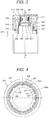
- Fig. 7 is an enlarged view of a part B shown in Fig. 6 .
- the rotor core 252 has magnetic gaps 257 at the outer side of the magnetic pole of the permanent magnet 254 (orthogonal to the magnetization direction). Such gap is formed to reduce the cogging torque and torque pulsation upon current application.
- the thickness of the magnetic gap 257 in the radial direction is smaller than the thickness of the permanent magnet 254 in the radial direction so that the rotor core at the inner periphery of the magnetic gap 257 regulates movement of the permanent magnet 254 in the circumferential direction.
- a core 256 between the magnetic insertion hole 253 into which the permanent magnet 254 is inserted and the outer periphery of the rotor core 252 is configured to have the smallest width W1 of a pole tip bridge 258 in the radial dimension.
- the magnet insertion hole 253 has clearance parts 263 as shown in Fig. 7 at both peripheral ends of the permanent magnet 254 at the inner periphery of the rotor core 252 so as not to be in contact with corners of the magnet 254.
- the clearance parts 263 are symmetrically formed with respect to a d-axis 300 shown in Fig. 6 , through which the magnetic flux passes the magnet center.
- the clearance part 263 has a facing surface 266 which faces the surface of the permanent magnet 254 inserted into the magnet insertion hole 253 via the gap at the axial center of the rotor cover 252.
- the facing surface 266 is formed by machining the rotor core 252 so as to be contiguous with the magnet insertion hole 253.
- the facing surface 266 of the clearance part 263 includes four inflection points so that two facing surfaces contiguous with the inflection points form the obtuse angle.
- Fig. 7 is a sectional view taken along line A-A of Fig. 3 , that is, the cross section formed by cutting the plane defined by circumferential and radial lines of the rotor core 252.
- Fig. 7 shows the four inflection points designated with 264a to 264d.
- the inflection part will be expressed by the inflection points, and, of the facing surface 266, the facing surface formed by connecting the adjacent inflection points is linearly expressed.
- the respective lines derived from connecting the four inflection points 264a to 264d form the obtuse angles. That is, the line for connecting the inflection points 264a and 264b, and the line for connecting the inflection points 264b and 264c form an obtuse angle 267a.
- the line for connecting the inflection points 264b and 264c, and the line for connecting the inflection points 264c and 264d also form an obtuse angle 267b.
- the clearance part is formed into a trapezoidal shape having a boundary 265 between the permanent magnet 254 and the magnet insertion hole 253 for regulating the side of the rotor core 252 in the circumferential direction as the lower base, and a side 266a (line connecting the inflection points 264b and 264c) of the clearance part 263 close to the inner periphery of the rotor core as the upper side. Therefore, the side 266a is formed parallel to the surface of the permanent magnet 254 at the counter side.
- the inflection points 264a to 264d cannot be cornered because of the rotor core manufacturing, each of which has a corner R equal to or smaller than R1.
- the corner R is included by the inflection point.
- This embodiment uses the line formed by connecting the inflection points of the clearance part 263. It is also possible to use the boundary line with large radius of curvature.
- the aforementioned structure allows stress dispersion to the respective angled parts defined by the inflection points 264a to 264d of the clearance part 263. As a result, stress to the clearance part 263 may be reduced by avoiding the stress concentration to the specific angled part, thus allowing high speed rotation of the rotor 250.
- the clearance part 263 having the inflection points and each obtuse angle formed by two lines contiguous with the points ensures suppression of the stress concentration.
- the obtuse angle formed by the two lines contiguous with the inflection points, and the line (the facing surface of the clearance part 263) parallel to the surface of the permanent magnet 254 such as the side 266a shown in Fig. 7 allow the clearance part 263 to be shaped parallel to the direction of the vector of the stress. This makes it possible to further improve the stress concentration suppression effect.
- inflection part Four or more inflection points (inflection part) are sufficient to allow the two lines contiguous with the inflection points to form the obtuse angle easily. Therefore, the more the number of the inflection points becomes, the higher the stress concentration suppression effect is improved.
- the stress concentration suppression effect is less effective than the case of four or more inflection points.
- the stress concentration suppression effect is still expected so long as the two lines contiguous with the inflection points form the obtuse angle.
- an air layer is formed inside the clearance part 263 for dispersing the stress concentration. Therefore, it is difficult for the magnetic flux generated by the permanent magnet 254 to pass through such space than the inside of the rotor core 252.
- a large number of the clearance parts 263, for example, provided in the magnetization direction may be a little inferior in the efficient use of magnetic force of the magnet.
- those at the outer peripheral side of the rotor core 252 have no clearance parts. However, it is possible to form the clearance part at those at the outer peripheral side.
- the inside of the clearance part 263 is not necessarily formed as the air layer, but may be filled with the non-magnetic body which hardly passes the magnetic flux, for example the adhesive and resin, or the magnetic body which allows easy passage of the magnetic flux so long as such material has lower Young's modulus than that of the rotor core 252.
- the resultant stress reducing effect is similar to the one derived from the air layer inside the clearance part.
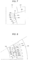
- Fig. 8 is an enlarged sectional view (taken along line A-A of Fig. 3 ) of the rotary electrical machine according to a second embodiment of the present invention.
- the permanent magnet 254 (and magnet insertion hole) for the single magnetic pole is divided into a pair of permanent magnets 254aa and 254ab in the circumferential direction in order to improve mechanical strength of the rotor core 252 against centrifugal force during rotation.
- An inter-magnet bridge portion 260 is provided between those permanent magnets so as to mechanically connect the rotor cores at the outer and inner peripheral sides of the permanent magnets.
- the second embodiment is configured to provide clearance parts at four facing corners of the paired permanent magnets 254aa, 254ab having the inter-magnet bridge portion 260 interposed between those magnets so as to reduce the stress concentration generated in the inter-magnet bridge portion 260.
- ten clearance parts 263a to 263j are formed for the paired permanent magnets 254aa, 254ab, respectively.
- the clearance parts 263 at the side of the inter-magnet bridge portion 260 include those formed at the radial side (263b, 263e, 263g, 263j), and the circumferential side (263c, 263d, 263h, 263i). However, they may be formed only either at the radial side or at the circumferential side.
- the paired permanent magnets 254aa, 254ab for the single magnetic pole are linearly arranged. They may be arranged in the manner other than linearly, which may still provide the advantageous effects of the present invention.
- the second embodiment is configured to provide the rotor having the permanent magnet for the single magnetic pole divided into a pair of permanent magnets to ensure reduction in the stress to the clearance part by suppressing the stress concentration to the respective corners of the permanent magnets. This makes it possible to realize high-speed rotation of the rotor.
- the inter-magnet bridge portion 260 disposed between the divided permanent magnets in pairs, resulting in high strength.
- Fig. 9 is an enlarged sectional view (taken along line A-A) of the rotary electrical machine according to a third embodiment of the present invention.
- the third embodiment is configured to have the permanent magnet 254 (and magnet insertion hole) constituted by three (or more) divided sections for the single magnetic pole.
- the inter-magnet bridge portions 260 are provided between the divided permanent magnets, respectively, and the clearance parts 263 are also formed at the corners of the facing permanent magnets 254 having the inter-magnet bridge portion 260 interposed therebetween as described referring to Fig. 7 .
- the rotor has three or more divided permanent magnets for the single magnetic pole to reduce the stress to the clearance part by suppressing the stress concentration to the respective corners of the permanent magnets. This makes it possible to realize high-speed rotation of the rotor.
- the inter-magnet bridge portions 260 are interposed between the divided permanent magnets, resulting in high strength.
- Fig. 10 is an enlarged sectional view (taken along line A-A of Fig. 3 ) of the rotary electrical machine according to a fourth embodiment of the present invention.
- the fourth embodiment is configured to arrange two divided permanent magnets 254 (and magnet insertion holes) in pairs for the single magnetic pole so as to form a V-like cross section having the inter-magnet bridge portion 260 interposed therebetween without being linearly arranged as shown in Fig. 8 .
- the clearance parts 263 are formed at the respective corners of the permanent magnets.
- the rotor is configured to divide the permanent magnet for the single magnetic pole into two sections, which are arranged to form the V-like cross section shape.
- This structure ensures reduction in the stress to the clearance part by suppressing the stress concentration to the respective corners of the permanent magnet, resulting in high rotation of the rotor.
- the inter-magnet bridge portion 260 is disposed between the divided paired permanent magnets, resulting in high strength.
- the divided paired permanent magnets are arranged to form the V-like cross section so as to allow easy passage of the magnetic flux, resulting in large reluctance torque.
- the present invention is not limited to the embodiments as described above, and may include various modifications.
- the embodiments have been described in detail for better understanding of the present invention, and are not necessarily restricted to the one provided with all the structures of the description.
- the structure of any one of the embodiments may be partially replaced with that of another embodiment.
Abstract
Description
- The present invention relates to a rotor for a rotary electrical machine.
- The rotary electrical machine for driving the vehicle has been demanded to be operated at higher rotation speed compared with the generally employed rotary electrical machine. In order to achieve the high-speed rotation, it is necessary to improve mechanical strength of the rotor against centrifugal force. For example,
Patent Literature 1 discloses a structure of the rotary electrical machine of permanent magnet type, which is configured to establish both high output and high mechanical rotation. - Patent Literature 1: Japanese Unexamined Patent
Application Publication No.2011-101504 - The rotary electrical machine disclosed in
Patent Literature 1 is configured to establish both high output and high mechanical rotation. However, the mechanical strength of the rotor against centrifugal force still has to be improved for higher speed rotation. - The present invention provides a rotor for rotary electrical machine provided with a stator, and a rotor which is disposed with a gap from the stator, including a magnet insertion hole formed in a rotor core and a permanent magnet inserted into the magnet insertion hole. A clearance part is formed at a position of the magnet insertion hole corresponding to a corner of the permanent magnet, which has a facing surface and inflection points so that an obtuse angle is formed by two facing surfaces contiguous with the inflection points.
- The present invention provides the rotor for the rotary electrical machine, which improves mechanical strength of the rotor against centrifugal force by alleviating stress concentration exerted to the clearance part of the magnet insertion hole of the rotor core.
- The technical problem, structure and advantageous effect other than those described above will be clarified by explanations of embodiments as described below.
-
-
Fig. 1 is a schematic view showing a structure of a hybrid type electric car mounted with a rotary electrical machine according to an embodiment of the present invention. -
Fig. 2 is a circuit diagram of apower converter 600 according to the embodiment of the present invention. -
Fig. 3 is a sectional view of the rotary electrical machine according to the embodiment of the present invention. -
Fig. 4 is a sectional view of astator 230 and arotor 250 according to the embodiment of the present invention, taken along line A-A ofFig. 3 . -
Fig. 5 is an explanatory view of a reluctance torque in the rotor for the rotary electrical machine. -
Fig. 6 is an enlarged sectional view of thestator 230 and therotor 250 according to a first embodiment of the present invention for a single magnetic pole. -
Fig. 7 is an enlarged view of a part B of aclearance part 263 shown inFig. 6 according to the first embodiment of the present invention. -
Fig. 8 is an enlarged sectional view of thestator 230 and therotor 250 for the single magnetic pole according to a second embodiment of the present invention. -
Fig. 9 is an enlarged sectional view of thestator 230 and therotor 250 for the single magnetic pole according to a third embodiment of the present invention. -
Fig. 10 is an enlarged sectional view of thestator 230 and therotor 250 for the single magnetic pole according to a fourth embodiment of the present invention. - Embodiments of the present invention will be described referring to the drawings.
- The embodiment is configured to ensure high rotation by reducing the stress which occurs in the clearance part of the magnet insertion hole of the rotor core as described below. This embodiment is suitably applicable to the drive motor for an electric car. The rotary electrical machine according to the present invention is applicable to a genuine electric car which is driven only by the rotary electrical machine, and a hybrid type electric car which is driven by both the engine and the rotary electrical machine. The following description will be made by taking the hybrid type electric car as an example.
-
Fig. 1 is a schematic view showing a structure of the hybrid type electric car mounted with the rotary electrical machine according to an embodiment of the present invention. Avehicle 100 is mounted with an engine 120, a first rotaryelectrical machine 200, a second rotaryelectrical machine 202, and abattery 180. Thebattery 180 supplies DC power to the rotaryelectrical machines electrical machines battery 180 and the rotaryelectrical machines power converter 600. The vehicle is also mounted with a not shown battery for supplying the low voltage power (for example, 14-volt power) so as to supply DC power to a control circuit to be described below. - The running torque generated by the engine 120 and the rotary
electrical machines front wheels 110 via a transmission 130 and adifferential gear 160. The transmission 130 is controlled by atransmission control device 134, and the engine 120 is controlled by anengine control device 124. Thebattery 180 is controlled by abattery control device 184. Thetransmission control device 134, theengine control device 124, thepower converter 600, thebattery control device 184, and an integratedcontrol device 170 are connected via acommunication line 174. - The integrated
control device 170 as a host control device of thetransmission control device 134, theengine control device 124, thepower converter 600, and thebattery control device 184 is configured to receive information with respect to each state of thetransmission control device 134, theengine control device 124, thepower converter 600, and thebattery control device 184, respectively via thecommunication line 174. Based on the received information, the integratedcontrol device 170 computes each command for controlling the respective control devices. The computed control commands will be transmitted to the corresponding control devices via thecommunication line 174. - The high-
voltage battery 180 constituted by a secondary battery such as a lithium ion battery and a nickel-hydrogen battery outputs high-voltage DC power ranging from 250 to 600 volts or higher. Thebattery control device 184 outputs the charge-discharge state of thebattery 180, and each state of the unit cell batteries that constitute thebattery 180 to the integratedcontrol device 170 via thecommunication line 174. - The integrated
control device 170 commands thepower converter 600 to be in the mode of generating operation upon determination that thebattery 180 needs to be charged based on the information from thebattery control device 184. The integratedcontrol device 170 mainly involves management of output torque generated by the engine 120, and the rotaryelectrical machines electrical machines transmission control device 134, theengine control device 124, and thepower converter 600. Based on the torque command from theintegrated control device 170, thepower converter 600 controls the rotaryelectrical machines - The
power converter 600 is provided with power semiconductors which constitute the inverter for operating the rotaryelectrical machines integrated control device 170, thepower converter 600 controls switching operations of the power semiconductor. The switching operation of the power semiconductor allows each of the rotaryelectrical machines - Upon operation of the rotary
electrical machines voltage battery 180 is supplied to the DC terminal of the inverter of thepower converter 600. Thepower converter 600 converts the DC power supplied by controlling the switching operation of the power semiconductor into three-phase AC power so as to be supplied to the rotaryelectrical machines electrical machines electrical machines electrical machines power converter 600, which will be supplied to the high-voltage battery 180 so as to be charged. -
Fig. 2 is a circuit diagram of thepower converter 600 shown inFig. 1 . Thepower converter 600 includes a first inverter unit for the rotaryelectrical machine 200, and a second inverter unit for the rotaryelectrical machine 202. The first inverter unit includes apower module 610, afirst drive circuit 652 for controlling switching operations of therespective power semiconductors 21 of thepower module 610, and acurrent sensor 660 for detecting the current of the rotaryelectrical machine 200. Thedrive circuit 652 is mounted on adrive circuit substrate 650. - Meanwhile, the second inverter unit includes a
power module 620, asecond drive circuit 656 for controlling switching operations of therespective power semiconductors 21 of thepower module 620, and acurrent sensor 662 for detecting the current of the rotaryelectrical machine 202. Thedrive circuit 656 is mounted on adrive circuit substrate 654. Acontrol circuit 648 mounted on acontrol circuit substrate 646, acapacitor module 630, and a transmission-reception circuit 644 mounted on aconnector substrate 642 are shared by the first and the second inverter units. - The
power modules drive circuits power modules battery 180 into the three-phase AC power so as to be supplied to the stator windings as armature windings of the corresponding rotaryelectrical machines power modules electrical machines voltage battery 180. - Referring to
Fig. 2 , each of thepower modules battery 180. Each of the series circuits includes thepower semiconductors 21 constituting an upper arm, and thepower semiconductors 21 constituting a lower arm. Thosepower semiconductors 21 are connected in series. Each circuit structure of thepower modules Fig. 2 . In the following explanation, the description will be made by taking thepower module 610 as the representative example. - In this embodiment, an IGBT (Insulated Gate type Bipolar Transistor) 21 is employed for the switching power semiconductor element. The
IGBT 21 includes three electrodes of a collector electrode, an emitter electrode, and a gate electrode. Adiode 38 is electrically coupled between the collector electrode and the emitter electrode of theIGBT 21. Thediode 38 includes two electrodes of a cathode electrode and an anode electrode. The cathode electrode is electrically coupled with the collector electrode of theIGBT 21, and the anode electrode is electrically coupled with the emitter electrode of theIGBT 21 so as to have the electrodes arranged in a forward direction from the emitter electrode to the collector electrode of theIGBT 21. - A MOSFET (Metal Oxide Semiconductor Field Effect Transistor) may also be employed for the switching power semiconductor element. The MOSFET includes three electrodes of a drain electrode, a source electrode and a gate electrode. The MOSFET includes a parasitic diode between the source electrode and the drain electrode so as to have the electrodes arranged in a forward direction from the drain electrode to the source electrode. Accordingly, the
diode 38 as shown inFig. 2 does not have to be provided. - Each arm of the respective phases is formed by electrically coupling the emitter electrode and the collector electrode of the
IGBT 21 in series. The drawing according to this embodiment only shows the single IGBT for the respective upper and lower arms of the phases. Actually, because of large current capacity to be controlled, a plurality of IGBTs are electrically coupled in parallel. The description will be made with respect to the single power semiconductor for simple explanation. - In the example as shown in
Fig. 2 , three IGBTs are employed for constituting each of the upper and lower arms at each phase. Each collector electrode of theIGBTs 21 for the upper arms of the respective phases is electrically coupled with the positive electrode side of thebattery 180, and each emitter electrode of theIGBTs 21 for the lower arms of the respective phases is electrically coupled with the negative electrode side of thebattery 180. The middle point (the connection point between the emitter electrode of the IGBT at the upper arm side and the collector electrode of the IGBT at the lower arm side) of each arm at the respective phases is electrically coupled with the armature winding (stator winding) of the corresponding phase of the subject rotaryelectrical machines - The
drive circuits power modules 610, 620) so that the drive signal is generated for driving theIGBT 21 based on the control signal output from thecontrol circuit 648. The drive signals generated by therespective drive circuits corresponding power modules drive circuits - The
control circuit 648 constitutes a control section of the respective inverter units (power modules 610, 620), which is configured as a microcomputer to compute the control signal (control value) for operating (ON-OFF) a plurality of switching power semiconductor elements. Thecontrol circuit 648 receives inputs of a torque command signal (torque command value) from the host control device, sensor outputs from thecurrent sensors resolver 224 to be described later) mounted on the rotaryelectrical machines control circuit 648 computes the control value based on those input signals, and outputs the control signal to thedrive circuits - The transmission-
reception circuit 644 mounted on theconnector substrate 642 is intended to electrically couple thepower converter 600 with the external control device for communication of the information with another device via thecommunication line 174 shown inFig. 1 . Thecapacitor module 630 constitutes a smoothing circuit for suppressing fluctuation in the DC voltage caused by the switching operation of theIGBT 21. It is electrically coupled in parallel with terminals at the DC sides of thefirst power module 610 and thesecond power module 620. -
Fig. 3 is a sectional view of the rotary electrical machine shown inFig. 1 . The rotaryelectrical machine 200 has substantially the same structure as that of the rotaryelectrical machine 202. The description with respect to the structure of the rotaryelectrical machine 200 will be made as a representative example hereinafter. The structure to be described below does not have to be employed for both the rotaryelectrical machines - The
stator 230 is held inside ahousing 212. Thestator 230 includes astator core 232 and a stator winding 238. Arotor 250 is rotatably supported at an inner periphery of thestator core 232 via a gap. Therotor 250 includes arotor core 252 fixed to ashaft 218, apermanent magnet 254, and anon-magnetic backing plate 226. Thehousing 212 includes a pair ofend brackets 214 provided withbearings 216. Theshaft 218 is rotatably held by thosebearings 216. - The
shaft 218 is provided with aresolver 224 for detecting the pole position, and rotation speed of therotor 250. The output from theresolver 224 is incorporated into thecontrol circuit 648 as shown inFig. 2 . Thecontrol circuit 648 outputs the control signal to thedrive circuit 652 based on the incorporated output. Thedrive circuit 652 outputs the drive signal based on the control signal to thepower module 610. Thepower module 610 performs the switching operation based on the control signal to convert the DC power supplied from thebattery 180 into the three-phase AC power. The three-phase AC power is supplied to the stator winding 238 as shown inFig. 3 to generate the rotating magnetic field in thestator 230. The frequency of the three-phase AC is controlled based on the output value of theresolver 224, and the phase of the three-phase AC to therotor 250 is controlled based on the output value of theresolver 224 as well. -
Fig. 4 is a sectional view of thestator 230 and therotor 250, taken along line A-A ofFig. 3. Fig. 4 omits thehousing 212, theshaft 218, and the stator winding 238. A large number ofslots 237 andteeth 236 are provided on the inner full circumference of thestator core 232 at equal intervals. Referring toFig. 4 , instead of numbering all the slots and teeth, only some of them are numbered as the representative example. A slot insulating material (not shown) is provided inside theslot 237, to which a plurality of phase windings including U-phase, V-phase, and W-phase constituting the stator winding 238 shown inFig. 3 are formed. In this embodiment, 72slots 237 are formed at equal intervals. - In a region around the outer circumference of the
rotor core 252, a plurality of magnet insertion holes 253, that is, 12 holes are formed along the circumferential direction so that rectangular magnets are inserted. The respective magnet insertion holes 253 are formed along the axial direction of therotor core 252, in which the permanent magnets 254 (254a, 254b) are embedded and fixed with adhesive, respectively. The width of themagnet insertion hole 253 in the circumferential direction is set to be larger than the width of thepermanent magnet 254 in the circumferential direction. The hole formed outside the magnetic pole of the permanent magnet 254 (end portions in the circumferential direction) functions asmagnetic gaps 257. Themagnetic gap 257 may be filled with the adhesive, or fixed integrally with thepermanent magnet 254 using the molding resin. In this embodiment, thepermanent magnets 254 serve as field poles of therotor 250, constituting the 12-pole structure. - The magnetization direction of the
permanent magnet 254 is radially directed, which is reversed for each field pole. Specifically, in the state where the stator side surface of thepermanent magnet 254a is at an N-pole, and the axial side surface is at an S-pole, the stator side surface of thepermanent magnet 254b is at the S-pole, and the axial side surface is at the N-pole. The aforementionedpermanent magnets - The
permanent magnet 254 may be magnetized, and then inserted into themagnet insertion hole 253. Alternatively, it may be inserted into themagnet insertion hole 253 of therotor core 252, and then magnetized through application of strong magnetic field. As the magnetizedpermanent magnet 254 becomes the strong magnet, magnetization of thepermanent magnet 254 before fixation to therotor 250 will generate high suction force between the magnet and therotor core 252 upon fixation of thepermanent magnet 254, resulting in interference with the assembling work. The high suction force of thepermanent magnet 254 may attract the dust, for example, iron powder. In view of productivity of the rotary electrical machine, it is preferable to magnetize thepermanent magnet 254 after it is inserted into therotor core 252. - The neodymium based, or samarium based sintered magnet, ferrite magnet, neodymium based bond magnet may be used for the
permanent magnet 254. The residual magnetic flux density of thepermanent magnet 254 is in the range from approximately 0.4 to 1.3 T. - As the three-phase AC is applied to the stator winding 238, the rotating magnetic field is generated in the
stator 230. The rotating magnetic field acts on thepermanent magnets rotor 250 to generate torque. This torque is expressed as a product of the component of the magnetic flux from thepermanent magnet 254, which is interlinked with the respective phase windings, and the component orthogonal to the interlinkage magnetic flux of the AC flowing through the respective phase windings. Assuming that the AC waveform is sinusoidal, the product of the fundamental wave component of the interlinkage magnetic flux and the fundamental wave component of the AC represents the time average component of the torque, and the product of the harmonic component of the interlinkage magnetic flux and the fundamental wave component of the AC represents the torque ripple as the harmonic component of the torque. That is, the torque ripple may be reduced by decreasing the harmonic component of the interlinkage magnetic flux. In other words, as the induced voltage is expressed as the product of the interlinkage magnetic flux and the angular acceleration of the rotating rotor, reduction in the harmonic component of the interlinkage magnetic flux is substantially the same as reduction in the harmonic component of the induced voltage. -
Fig. 5 is an explanatory view of the reluctance torque. Generally, the axis through which the magnetic flux passes the center of the magnet is referred to as a d-axis, and the axis through which the magnetic flux flows between inter-pole sections is referred to as a q axis. The core part at the inter-pole center of the magnet is referred to as an auxiliarysalient pole 259. Thepermanent magnet 254 provided in therotor 250 exhibits permeability which is substantially the same as that of air. When seen from the stator side, the d-axis part is magnetically concave, and the q-axis part is magnetically convex. The core part of the q-axis is called the salient pole. Therefore, the reluctance torque is caused by the difference in passability of the magnetic flux through the axis between the d-axis and q-axis, that is, salient pole ratio. -
Figs. 6 and7 show a structure of the first embodiment according to the present invention.Fig. 6 is an enlarged sectional view of the single magnetic pole shown inFig. 4 .Fig. 7 is an enlarged view of a part B shown inFig. 6 . Referring toFig. 6 , therotor core 252 hasmagnetic gaps 257 at the outer side of the magnetic pole of the permanent magnet 254 (orthogonal to the magnetization direction). Such gap is formed to reduce the cogging torque and torque pulsation upon current application. Furthermore, the thickness of themagnetic gap 257 in the radial direction is smaller than the thickness of thepermanent magnet 254 in the radial direction so that the rotor core at the inner periphery of themagnetic gap 257 regulates movement of thepermanent magnet 254 in the circumferential direction. A core 256 between themagnetic insertion hole 253 into which thepermanent magnet 254 is inserted and the outer periphery of therotor core 252 is configured to have the smallest width W1 of apole tip bridge 258 in the radial dimension. - The
magnet insertion hole 253 hasclearance parts 263 as shown inFig. 7 at both peripheral ends of thepermanent magnet 254 at the inner periphery of therotor core 252 so as not to be in contact with corners of themagnet 254. Theclearance parts 263 are symmetrically formed with respect to a d-axis 300 shown inFig. 6 , through which the magnetic flux passes the magnet center. - The
clearance part 263 has a facingsurface 266 which faces the surface of thepermanent magnet 254 inserted into themagnet insertion hole 253 via the gap at the axial center of therotor cover 252. The facingsurface 266 is formed by machining therotor core 252 so as to be contiguous with themagnet insertion hole 253. - The facing
surface 266 of theclearance part 263 includes four inflection points so that two facing surfaces contiguous with the inflection points form the obtuse angle. -
Fig. 7 is a sectional view taken along line A-A ofFig. 3 , that is, the cross section formed by cutting the plane defined by circumferential and radial lines of therotor core 252.Fig. 7 shows the four inflection points designated with 264a to 264d. In the following description, the inflection part will be expressed by the inflection points, and, of the facingsurface 266, the facing surface formed by connecting the adjacent inflection points is linearly expressed. - The respective lines derived from connecting the four
inflection points 264a to 264d form the obtuse angles. That is, the line for connecting theinflection points inflection points obtuse angle 267a. The line for connecting theinflection points inflection points obtuse angle 267b. - In this embodiment, the clearance part is formed into a trapezoidal shape having a
boundary 265 between thepermanent magnet 254 and themagnet insertion hole 253 for regulating the side of therotor core 252 in the circumferential direction as the lower base, and aside 266a (line connecting theinflection points clearance part 263 close to the inner periphery of the rotor core as the upper side. Therefore, theside 266a is formed parallel to the surface of thepermanent magnet 254 at the counter side. - The
inflection points 264a to 264d cannot be cornered because of the rotor core manufacturing, each of which has a corner R equal to or smaller than R1. The corner R is included by the inflection point. This embodiment uses the line formed by connecting the inflection points of theclearance part 263. It is also possible to use the boundary line with large radius of curvature. - The aforementioned structure allows stress dispersion to the respective angled parts defined by the
inflection points 264a to 264d of theclearance part 263. As a result, stress to theclearance part 263 may be reduced by avoiding the stress concentration to the specific angled part, thus allowing high speed rotation of therotor 250. - In other words, the
clearance part 263 having the inflection points and each obtuse angle formed by two lines contiguous with the points ensures suppression of the stress concentration. - The obtuse angle formed by the two lines contiguous with the inflection points, and the line (the facing surface of the clearance part 263) parallel to the surface of the
permanent magnet 254 such as theside 266a shown inFig. 7 allow theclearance part 263 to be shaped parallel to the direction of the vector of the stress. This makes it possible to further improve the stress concentration suppression effect. - Four or more inflection points (inflection part) are sufficient to allow the two lines contiguous with the inflection points to form the obtuse angle easily. Therefore, the more the number of the inflection points becomes, the higher the stress concentration suppression effect is improved.
- In the case of three inflection points, the stress concentration suppression effect is less effective than the case of four or more inflection points. However, the stress concentration suppression effect is still expected so long as the two lines contiguous with the inflection points form the obtuse angle.
- In this embodiment, an air layer is formed inside the
clearance part 263 for dispersing the stress concentration. Therefore, it is difficult for the magnetic flux generated by thepermanent magnet 254 to pass through such space than the inside of therotor core 252. A large number of theclearance parts 263, for example, provided in the magnetization direction may be a little inferior in the efficient use of magnetic force of the magnet. - Referring to the embodiment shown in
Fig. 6 , among four corners of thepermanent magnet 254, those at the outer peripheral side of therotor core 252 have no clearance parts. However, it is possible to form the clearance part at those at the outer peripheral side. - The inside of the
clearance part 263 is not necessarily formed as the air layer, but may be filled with the non-magnetic body which hardly passes the magnetic flux, for example the adhesive and resin, or the magnetic body which allows easy passage of the magnetic flux so long as such material has lower Young's modulus than that of therotor core 252. The resultant stress reducing effect is similar to the one derived from the air layer inside the clearance part. -
Fig. 8 is an enlarged sectional view (taken along line A-A ofFig. 3 ) of the rotary electrical machine according to a second embodiment of the present invention. In the second embodiment, the permanent magnet 254 (and magnet insertion hole) for the single magnetic pole is divided into a pair of permanent magnets 254aa and 254ab in the circumferential direction in order to improve mechanical strength of therotor core 252 against centrifugal force during rotation. Aninter-magnet bridge portion 260 is provided between those permanent magnets so as to mechanically connect the rotor cores at the outer and inner peripheral sides of the permanent magnets. - The second embodiment is configured to provide clearance parts at four facing corners of the paired permanent magnets 254aa, 254ab having the
inter-magnet bridge portion 260 interposed between those magnets so as to reduce the stress concentration generated in theinter-magnet bridge portion 260. - Specifically, ten
clearance parts 263a to 263j, each of which is similar to theclearance part 263 described referring toFig. 7 , are formed for the paired permanent magnets 254aa, 254ab, respectively. - The
clearance parts 263 at the side of theinter-magnet bridge portion 260 include those formed at the radial side (263b, 263e, 263g, 263j), and the circumferential side (263c, 263d, 263h, 263i). However, they may be formed only either at the radial side or at the circumferential side. The paired permanent magnets 254aa, 254ab for the single magnetic pole are linearly arranged. They may be arranged in the manner other than linearly, which may still provide the advantageous effects of the present invention. - As described above, the second embodiment is configured to provide the rotor having the permanent magnet for the single magnetic pole divided into a pair of permanent magnets to ensure reduction in the stress to the clearance part by suppressing the stress concentration to the respective corners of the permanent magnets. This makes it possible to realize high-speed rotation of the rotor. The
inter-magnet bridge portion 260 disposed between the divided permanent magnets in pairs, resulting in high strength. -
Fig. 9 is an enlarged sectional view (taken along line A-A) of the rotary electrical machine according to a third embodiment of the present invention. The third embodiment is configured to have the permanent magnet 254 (and magnet insertion hole) constituted by three (or more) divided sections for the single magnetic pole. Theinter-magnet bridge portions 260 are provided between the divided permanent magnets, respectively, and theclearance parts 263 are also formed at the corners of the facingpermanent magnets 254 having theinter-magnet bridge portion 260 interposed therebetween as described referring toFig. 7 . - According to the third embodiment, the rotor has three or more divided permanent magnets for the single magnetic pole to reduce the stress to the clearance part by suppressing the stress concentration to the respective corners of the permanent magnets. This makes it possible to realize high-speed rotation of the rotor. The
inter-magnet bridge portions 260 are interposed between the divided permanent magnets, resulting in high strength. -
Fig. 10 is an enlarged sectional view (taken along line A-A ofFig. 3 ) of the rotary electrical machine according to a fourth embodiment of the present invention. The fourth embodiment is configured to arrange two divided permanent magnets 254 (and magnet insertion holes) in pairs for the single magnetic pole so as to form a V-like cross section having theinter-magnet bridge portion 260 interposed therebetween without being linearly arranged as shown inFig. 8 . Like theclearance parts 263a to 263j as shown inFig. 8 , theclearance parts 263 are formed at the respective corners of the permanent magnets. - According to the fourth embodiment, the rotor is configured to divide the permanent magnet for the single magnetic pole into two sections, which are arranged to form the V-like cross section shape. This structure ensures reduction in the stress to the clearance part by suppressing the stress concentration to the respective corners of the permanent magnet, resulting in high rotation of the rotor. The
inter-magnet bridge portion 260 is disposed between the divided paired permanent magnets, resulting in high strength. The divided paired permanent magnets are arranged to form the V-like cross section so as to allow easy passage of the magnetic flux, resulting in large reluctance torque. - The present invention is not limited to the embodiments as described above, and may include various modifications. The embodiments have been described in detail for better understanding of the present invention, and are not necessarily restricted to the one provided with all the structures of the description. The structure of any one of the embodiments may be partially replaced with that of another embodiment. Alternatively, it is possible to add the structure of any one of the embodiment to that of another embodiment. It is also possible to have the part of the structure of the respective embodiments added to, removed from and replaced with another structure.
-
- 100
- vehicle
- 230
- stator
- 250
- rotor
- 252
- rotor core
- 254, 254a, 254b, 254aa, 254ab
- permanent magnet
- 257
- magnetic gap
- 258
- pole tip bridge
- 260
- inter-magnet bridge portion
- 263, 263a to 263j
- clearance part
- 264a to 264d
- inflection point
- 265
- boundary
- 266
- facing surface
- 266a
- side
Claims (7)
- A rotor for rotary electrical machine provided with a stator, and a rotor disposed with a gap from the stator, and having a rotor core including a plurality of magnetic poles, each magnetic pole of the rotor having a magnet insertion hole formed in the rotor core, and a permanent magnet inserted into the magnet insertion hole,
wherein a clearance part is formed at a position of the magnet insertion hole corresponding to a corner of the inserted permanent magnet, which has a facing surface that is formed to face a surface of the permanent magnet via a gap; and
the facing surface of the clearance part has inflection points so that an obtuse angle is formed by the two facing surfaces contiguous with the inflection points. - The rotor for rotary electrical machine according to claim 1, wherein the clearance part includes four or more inflection points.
- The rotor for rotary electrical machine according to claim 1 or 2, wherein the facing surface of the clearance part has a facing surface parallel to the surface of the permanent magnet counter to the facing surface of the clearance part.
- The rotor for rotary electrical machine according to any one of claims 1 to 3, wherein a trapezoidal or a substantially trapezoidal cross section is formed by cutting a region defined by the facing surface of the clearance part with the inflection points and the surface of the permanent magnet counter to the facing surface of the clearance part along a plane defined by circumferential and radial lines of the rotor core.
- The rotor for rotary electrical machine according to any one of claims 1 to 4,
wherein the rotor includes a plurality of divided permanent magnets for a single magnetic pole, and a plurality of magnet insertion holes through which the permanent magnets are respectively inserted, and
the clearance part is provided at each position of the magnet insertion holes corresponding to the corners of the divided permanent magnets. - The rotor for rotary electrical machine according to claim 5, wherein the divided permanent magnets are a pair of permanent magnets, which are arranged to form a V-like cross section shape formed by cutting the pair of permanent magnets along a plane defined by circumferential and radial lines of the rotor core.
- A rotary electrical machine comprising the rotor according to any one of claims 1 to 6.
Applications Claiming Priority (2)
| Application Number | Priority Date | Filing Date | Title |
|---|---|---|---|
| JP2013096159 | 2013-05-01 | ||
| PCT/JP2014/055902 WO2014178227A1 (en) | 2013-05-01 | 2014-03-07 | Rotary electrical machine, and rotor for rotary electrical machine |
Publications (3)
| Publication Number | Publication Date |
|---|---|
| EP2993761A1 true EP2993761A1 (en) | 2016-03-09 |
| EP2993761A4 EP2993761A4 (en) | 2016-12-28 |
| EP2993761B1 EP2993761B1 (en) | 2018-06-06 |
Family
ID=51843363
Family Applications (1)
| Application Number | Title | Priority Date | Filing Date |
|---|---|---|---|
| EP14791950.0A Active EP2993761B1 (en) | 2013-05-01 | 2014-03-07 | Rotary electrical machine, and rotor for rotary electrical machine |
Country Status (5)
| Country | Link |
|---|---|
| US (1) | US10511198B2 (en) |
| EP (1) | EP2993761B1 (en) |
| JP (1) | JP6111327B2 (en) |
| CN (1) | CN105340155B (en) |
| WO (1) | WO2014178227A1 (en) |
Families Citing this family (9)
| Publication number | Priority date | Publication date | Assignee | Title |
|---|---|---|---|---|
| CN107431397B (en) * | 2015-03-16 | 2020-06-12 | 株式会社丰田自动织机 | Rotor of rotating electric machine |
| US10734856B2 (en) * | 2015-09-16 | 2020-08-04 | Mitsubishi Electric Corporation | Rotor for rotary electric machine and rotary electric machine |
| WO2017061244A1 (en) * | 2015-10-06 | 2017-04-13 | 三菱電機株式会社 | Rotating electric machine |
| CN105774512B (en) * | 2016-03-01 | 2018-09-14 | 至玥腾风科技投资集团有限公司 | A kind of extended-range electric passenger vehicle of engine behind front wheel |
| JP6702550B2 (en) * | 2016-08-31 | 2020-06-03 | 株式会社東芝 | Rotor and reluctance motor |
| CN110690775B (en) * | 2018-07-05 | 2021-11-19 | 爱信艾达株式会社 | Rotor and rotating electrical machine |
| DE102019104072A1 (en) * | 2019-02-19 | 2020-08-20 | Bayerische Motoren Werke Aktiengesellschaft | Cavity structure for permanently excited electrical machines with embedded magnets |
| JP2021122163A (en) * | 2020-01-31 | 2021-08-26 | 日立金属株式会社 | Rotary electric machine |
| US11916435B2 (en) * | 2020-05-22 | 2024-02-27 | Duxion Motors, Inc. | Split electric machine for retrofit hybrid propulsion systems |
Family Cites Families (18)
| Publication number | Priority date | Publication date | Assignee | Title |
|---|---|---|---|---|
| US4339874A (en) * | 1978-12-26 | 1982-07-20 | The Garrett Corporation | Method of making a wedge-shaped permanent magnet rotor assembly |
| JP3598887B2 (en) * | 1999-06-28 | 2004-12-08 | トヨタ自動車株式会社 | Rotor of permanent magnet type rotating machine |
| JP4867194B2 (en) * | 2005-04-28 | 2012-02-01 | トヨタ自動車株式会社 | Rotor |
| JP5349732B2 (en) * | 2005-12-06 | 2013-11-20 | パナソニック株式会社 | motor |
| JP2008211934A (en) * | 2007-02-27 | 2008-09-11 | Toyota Industries Corp | Rotating electrical machine and rotator therefor |
| JP5443778B2 (en) * | 2009-01-30 | 2014-03-19 | 東芝産業機器製造株式会社 | Rotor of permanent magnet type rotating electric machine and rotating electric machine thereof |
| DE102009026524A1 (en) * | 2009-05-28 | 2010-12-02 | Robert Bosch Gmbh | Electric machine |
| JP5723524B2 (en) | 2009-11-06 | 2015-05-27 | 日立オートモティブシステムズ株式会社 | Rotating electric machines and electric vehicles |
| DE102010043575A1 (en) * | 2009-12-18 | 2011-06-22 | Robert Bosch GmbH, 70469 | Rotor for an electric machine |
| JP2011182552A (en) | 2010-03-01 | 2011-09-15 | Toyota Motor Corp | Rotor core, and core for rotary electric machine |
| JP5418467B2 (en) * | 2010-11-02 | 2014-02-19 | 株式会社安川電機 | Rotating electric machine |
| JP5643127B2 (en) * | 2011-02-03 | 2014-12-17 | トヨタ自動車株式会社 | Rotating machine rotor |
| JP2012186889A (en) | 2011-03-03 | 2012-09-27 | Nippon Soken Inc | Rotary electric machine |
| CN202221930U (en) * | 2011-08-11 | 2012-05-16 | 中山大洋电机制造有限公司 | Motor permanent magnet rotor structure |
| EP2568578A3 (en) * | 2011-09-07 | 2017-12-06 | Samsung Electronics Co., Ltd. | Motor and washing machine having the same |
| JP5730736B2 (en) | 2011-10-04 | 2015-06-10 | 日立オートモティブシステムズ株式会社 | Permanent magnet type rotating electric machine and vehicle equipped with permanent magnet type rotating electric machine |
| EP2592718A2 (en) * | 2011-11-08 | 2013-05-15 | Kabushiki Kaisha Yaskawa Denki | Rotor core, rotor, and rotating electric machine |
| JP5858232B2 (en) * | 2012-02-17 | 2016-02-10 | 日本電産株式会社 | Rotor core, motor, and motor manufacturing method |
-
2014
- 2014-03-07 WO PCT/JP2014/055902 patent/WO2014178227A1/en active Application Filing
- 2014-03-07 EP EP14791950.0A patent/EP2993761B1/en active Active
- 2014-03-07 CN CN201480036532.9A patent/CN105340155B/en active Active
- 2014-03-07 JP JP2015514771A patent/JP6111327B2/en active Active
- 2014-03-07 US US14/888,659 patent/US10511198B2/en active Active
Also Published As
| Publication number | Publication date |
|---|---|
| WO2014178227A1 (en) | 2014-11-06 |
| EP2993761B1 (en) | 2018-06-06 |
| JP6111327B2 (en) | 2017-04-05 |
| EP2993761A4 (en) | 2016-12-28 |
| CN105340155A (en) | 2016-02-17 |
| JPWO2014178227A1 (en) | 2017-02-23 |
| CN105340155B (en) | 2018-07-06 |
| US20160141926A1 (en) | 2016-05-19 |
| US10511198B2 (en) | 2019-12-17 |
Similar Documents
| Publication | Publication Date | Title |
|---|---|---|
| EP2993761B1 (en) | Rotary electrical machine, and rotor for rotary electrical machine | |
| JP5730736B2 (en) | Permanent magnet type rotating electric machine and vehicle equipped with permanent magnet type rotating electric machine | |
| US10056794B2 (en) | Rotating electric machine and vehicle equipped with the rotating electric machine | |
| EP2498375B1 (en) | Dynamo-electric machine and automobile | |
| CN109327088B (en) | Rotating electrical machine and electric vehicle provided with same | |
| US20170353071A1 (en) | Rotary Electric Machine and Vehicle Provided with the Same | |
| JP7113003B2 (en) | Rotor of rotary electric machine and rotary electric machine provided with the same | |
| JP2020174529A (en) | Rotor of rotary electric machine, rotary electric machine, and vehicle | |
| US11735968B2 (en) | Rotary electric machine and vehicle provided with the same | |
| JP6670767B2 (en) | Rotating electric machine | |
| CN111264018B (en) | Rotor of rotating electric machine and rotating electric machine using the same | |
| JP2016158401A (en) | Rotor for rotary electric machine, and rotary electric machine with the same | |
| WO2023238312A1 (en) | Rotor of dynamo-electric machine, dynamo-electric machine, and electric-powered vehicle provided with dynamo-electric machine |
Legal Events
| Date | Code | Title | Description |
|---|---|---|---|
| PUAI | Public reference made under article 153(3) epc to a published international application that has entered the european phase |
Free format text: ORIGINAL CODE: 0009012 |
|
| 17P | Request for examination filed |
Effective date: 20151201 |
|
| AK | Designated contracting states |
Kind code of ref document: A1 Designated state(s): AL AT BE BG CH CY CZ DE DK EE ES FI FR GB GR HR HU IE IS IT LI LT LU LV MC MK MT NL NO PL PT RO RS SE SI SK SM TR |
|
| AX | Request for extension of the european patent |
Extension state: BA ME |
|
| DAX | Request for extension of the european patent (deleted) | ||
| A4 | Supplementary search report drawn up and despatched |
Effective date: 20161124 |
|
| RIC1 | Information provided on ipc code assigned before grant |
Ipc: H02K 1/27 20060101AFI20161118BHEP Ipc: H02K 1/22 20060101ALI20161118BHEP |
|
| REG | Reference to a national code |
Ref country code: DE Ref legal event code: R079 Ref document number: 602014026737 Country of ref document: DE Free format text: PREVIOUS MAIN CLASS: H02K0001270000 Ipc: B60L0011120000 |
|
| GRAP | Despatch of communication of intention to grant a patent |
Free format text: ORIGINAL CODE: EPIDOSNIGR1 |
|
| STAA | Information on the status of an ep patent application or granted ep patent |
Free format text: STATUS: GRANT OF PATENT IS INTENDED |
|
| RIC1 | Information provided on ipc code assigned before grant |
Ipc: H02K 1/27 20060101ALI20171113BHEP Ipc: B60L 15/00 20060101ALI20171113BHEP Ipc: B60L 11/14 20060101ALI20171113BHEP Ipc: B60L 15/20 20060101ALI20171113BHEP Ipc: B60L 11/12 20060101AFI20171113BHEP |
|
| INTG | Intention to grant announced |
Effective date: 20171211 |
|
| GRAS | Grant fee paid |
Free format text: ORIGINAL CODE: EPIDOSNIGR3 |
|
| GRAA | (expected) grant |
Free format text: ORIGINAL CODE: 0009210 |
|
| STAA | Information on the status of an ep patent application or granted ep patent |
Free format text: STATUS: THE PATENT HAS BEEN GRANTED |
|
| RIN1 | Information on inventor provided before grant (corrected) |
Inventor name: HAMANO, HIROSHI Inventor name: KOBAYASHI, RYOJI Inventor name: OSHIDA, MANABU Inventor name: SAITO, YASUYUKI Inventor name: UMESAKI, YOSUKE Inventor name: KANO, YUJI |
|
| AK | Designated contracting states |
Kind code of ref document: B1 Designated state(s): AL AT BE BG CH CY CZ DE DK EE ES FI FR GB GR HR HU IE IS IT LI LT LU LV MC MK MT NL NO PL PT RO RS SE SI SK SM TR |
|
| REG | Reference to a national code |
Ref country code: GB Ref legal event code: FG4D |
|
| REG | Reference to a national code |
Ref country code: CH Ref legal event code: EP Ref country code: AT Ref legal event code: REF Ref document number: 1005701 Country of ref document: AT Kind code of ref document: T Effective date: 20180615 |
|
| REG | Reference to a national code |
Ref country code: IE Ref legal event code: FG4D |
|
| REG | Reference to a national code |
Ref country code: DE Ref legal event code: R096 Ref document number: 602014026737 Country of ref document: DE |
|
| REG | Reference to a national code |
Ref country code: NL Ref legal event code: MP Effective date: 20180606 |
|
| REG | Reference to a national code |
Ref country code: LT Ref legal event code: MG4D |
|
| PG25 | Lapsed in a contracting state [announced via postgrant information from national office to epo] |
Ref country code: FI Free format text: LAPSE BECAUSE OF FAILURE TO SUBMIT A TRANSLATION OF THE DESCRIPTION OR TO PAY THE FEE WITHIN THE PRESCRIBED TIME-LIMIT Effective date: 20180606 Ref country code: NO Free format text: LAPSE BECAUSE OF FAILURE TO SUBMIT A TRANSLATION OF THE DESCRIPTION OR TO PAY THE FEE WITHIN THE PRESCRIBED TIME-LIMIT Effective date: 20180906 Ref country code: LT Free format text: LAPSE BECAUSE OF FAILURE TO SUBMIT A TRANSLATION OF THE DESCRIPTION OR TO PAY THE FEE WITHIN THE PRESCRIBED TIME-LIMIT Effective date: 20180606 Ref country code: ES Free format text: LAPSE BECAUSE OF FAILURE TO SUBMIT A TRANSLATION OF THE DESCRIPTION OR TO PAY THE FEE WITHIN THE PRESCRIBED TIME-LIMIT Effective date: 20180606 Ref country code: SE Free format text: LAPSE BECAUSE OF FAILURE TO SUBMIT A TRANSLATION OF THE DESCRIPTION OR TO PAY THE FEE WITHIN THE PRESCRIBED TIME-LIMIT Effective date: 20180606 Ref country code: CY Free format text: LAPSE BECAUSE OF FAILURE TO SUBMIT A TRANSLATION OF THE DESCRIPTION OR TO PAY THE FEE WITHIN THE PRESCRIBED TIME-LIMIT Effective date: 20180606 Ref country code: BG Free format text: LAPSE BECAUSE OF FAILURE TO SUBMIT A TRANSLATION OF THE DESCRIPTION OR TO PAY THE FEE WITHIN THE PRESCRIBED TIME-LIMIT Effective date: 20180906 |
|
| REG | Reference to a national code |
Ref country code: DE Ref legal event code: R079 Ref document number: 602014026737 Country of ref document: DE Free format text: PREVIOUS MAIN CLASS: B60L0011120000 Ipc: B60L0050150000 |
|
| PG25 | Lapsed in a contracting state [announced via postgrant information from national office to epo] |
Ref country code: LV Free format text: LAPSE BECAUSE OF FAILURE TO SUBMIT A TRANSLATION OF THE DESCRIPTION OR TO PAY THE FEE WITHIN THE PRESCRIBED TIME-LIMIT Effective date: 20180606 Ref country code: RS Free format text: LAPSE BECAUSE OF FAILURE TO SUBMIT A TRANSLATION OF THE DESCRIPTION OR TO PAY THE FEE WITHIN THE PRESCRIBED TIME-LIMIT Effective date: 20180606 Ref country code: GR Free format text: LAPSE BECAUSE OF FAILURE TO SUBMIT A TRANSLATION OF THE DESCRIPTION OR TO PAY THE FEE WITHIN THE PRESCRIBED TIME-LIMIT Effective date: 20180907 Ref country code: HR Free format text: LAPSE BECAUSE OF FAILURE TO SUBMIT A TRANSLATION OF THE DESCRIPTION OR TO PAY THE FEE WITHIN THE PRESCRIBED TIME-LIMIT Effective date: 20180606 |
|
| REG | Reference to a national code |
Ref country code: AT Ref legal event code: MK05 Ref document number: 1005701 Country of ref document: AT Kind code of ref document: T Effective date: 20180606 |
|
| PG25 | Lapsed in a contracting state [announced via postgrant information from national office to epo] |
Ref country code: NL Free format text: LAPSE BECAUSE OF FAILURE TO SUBMIT A TRANSLATION OF THE DESCRIPTION OR TO PAY THE FEE WITHIN THE PRESCRIBED TIME-LIMIT Effective date: 20180606 |
|
| PG25 | Lapsed in a contracting state [announced via postgrant information from national office to epo] |
Ref country code: PL Free format text: LAPSE BECAUSE OF FAILURE TO SUBMIT A TRANSLATION OF THE DESCRIPTION OR TO PAY THE FEE WITHIN THE PRESCRIBED TIME-LIMIT Effective date: 20180606 Ref country code: EE Free format text: LAPSE BECAUSE OF FAILURE TO SUBMIT A TRANSLATION OF THE DESCRIPTION OR TO PAY THE FEE WITHIN THE PRESCRIBED TIME-LIMIT Effective date: 20180606 Ref country code: AT Free format text: LAPSE BECAUSE OF FAILURE TO SUBMIT A TRANSLATION OF THE DESCRIPTION OR TO PAY THE FEE WITHIN THE PRESCRIBED TIME-LIMIT Effective date: 20180606 Ref country code: IS Free format text: LAPSE BECAUSE OF FAILURE TO SUBMIT A TRANSLATION OF THE DESCRIPTION OR TO PAY THE FEE WITHIN THE PRESCRIBED TIME-LIMIT Effective date: 20181006 Ref country code: SK Free format text: LAPSE BECAUSE OF FAILURE TO SUBMIT A TRANSLATION OF THE DESCRIPTION OR TO PAY THE FEE WITHIN THE PRESCRIBED TIME-LIMIT Effective date: 20180606 Ref country code: CZ Free format text: LAPSE BECAUSE OF FAILURE TO SUBMIT A TRANSLATION OF THE DESCRIPTION OR TO PAY THE FEE WITHIN THE PRESCRIBED TIME-LIMIT Effective date: 20180606 Ref country code: RO Free format text: LAPSE BECAUSE OF FAILURE TO SUBMIT A TRANSLATION OF THE DESCRIPTION OR TO PAY THE FEE WITHIN THE PRESCRIBED TIME-LIMIT Effective date: 20180606 |
|
| PG25 | Lapsed in a contracting state [announced via postgrant information from national office to epo] |
Ref country code: IT Free format text: LAPSE BECAUSE OF FAILURE TO SUBMIT A TRANSLATION OF THE DESCRIPTION OR TO PAY THE FEE WITHIN THE PRESCRIBED TIME-LIMIT Effective date: 20180606 Ref country code: SM Free format text: LAPSE BECAUSE OF FAILURE TO SUBMIT A TRANSLATION OF THE DESCRIPTION OR TO PAY THE FEE WITHIN THE PRESCRIBED TIME-LIMIT Effective date: 20180606 |
|
| REG | Reference to a national code |
Ref country code: DE Ref legal event code: R097 Ref document number: 602014026737 Country of ref document: DE |
|
| PLBE | No opposition filed within time limit |
Free format text: ORIGINAL CODE: 0009261 |
|
| STAA | Information on the status of an ep patent application or granted ep patent |
Free format text: STATUS: NO OPPOSITION FILED WITHIN TIME LIMIT |
|
| 26N | No opposition filed |
Effective date: 20190307 |
|
| PG25 | Lapsed in a contracting state [announced via postgrant information from national office to epo] |
Ref country code: DK Free format text: LAPSE BECAUSE OF FAILURE TO SUBMIT A TRANSLATION OF THE DESCRIPTION OR TO PAY THE FEE WITHIN THE PRESCRIBED TIME-LIMIT Effective date: 20180606 Ref country code: SI Free format text: LAPSE BECAUSE OF FAILURE TO SUBMIT A TRANSLATION OF THE DESCRIPTION OR TO PAY THE FEE WITHIN THE PRESCRIBED TIME-LIMIT Effective date: 20180606 |
|
| PG25 | Lapsed in a contracting state [announced via postgrant information from national office to epo] |
Ref country code: MC Free format text: LAPSE BECAUSE OF FAILURE TO SUBMIT A TRANSLATION OF THE DESCRIPTION OR TO PAY THE FEE WITHIN THE PRESCRIBED TIME-LIMIT Effective date: 20180606 |
|
| REG | Reference to a national code |
Ref country code: CH Ref legal event code: PL |
|
| GBPC | Gb: european patent ceased through non-payment of renewal fee |
Effective date: 20190307 |
|
| PG25 | Lapsed in a contracting state [announced via postgrant information from national office to epo] |
Ref country code: LU Free format text: LAPSE BECAUSE OF NON-PAYMENT OF DUE FEES Effective date: 20190307 Ref country code: AL Free format text: LAPSE BECAUSE OF FAILURE TO SUBMIT A TRANSLATION OF THE DESCRIPTION OR TO PAY THE FEE WITHIN THE PRESCRIBED TIME-LIMIT Effective date: 20180606 |
|
| REG | Reference to a national code |
Ref country code: BE Ref legal event code: MM Effective date: 20190331 |
|
| PG25 | Lapsed in a contracting state [announced via postgrant information from national office to epo] |
Ref country code: GB Free format text: LAPSE BECAUSE OF NON-PAYMENT OF DUE FEES Effective date: 20190307 Ref country code: LI Free format text: LAPSE BECAUSE OF NON-PAYMENT OF DUE FEES Effective date: 20190331 Ref country code: IE Free format text: LAPSE BECAUSE OF NON-PAYMENT OF DUE FEES Effective date: 20190307 Ref country code: CH Free format text: LAPSE BECAUSE OF NON-PAYMENT OF DUE FEES Effective date: 20190331 |
|
| PG25 | Lapsed in a contracting state [announced via postgrant information from national office to epo] |
Ref country code: FR Free format text: LAPSE BECAUSE OF NON-PAYMENT OF DUE FEES Effective date: 20190331 Ref country code: BE Free format text: LAPSE BECAUSE OF NON-PAYMENT OF DUE FEES Effective date: 20190331 |
|
| PG25 | Lapsed in a contracting state [announced via postgrant information from national office to epo] |
Ref country code: TR Free format text: LAPSE BECAUSE OF FAILURE TO SUBMIT A TRANSLATION OF THE DESCRIPTION OR TO PAY THE FEE WITHIN THE PRESCRIBED TIME-LIMIT Effective date: 20180606 |
|
| PG25 | Lapsed in a contracting state [announced via postgrant information from national office to epo] |
Ref country code: MT Free format text: LAPSE BECAUSE OF NON-PAYMENT OF DUE FEES Effective date: 20190307 Ref country code: PT Free format text: LAPSE BECAUSE OF FAILURE TO SUBMIT A TRANSLATION OF THE DESCRIPTION OR TO PAY THE FEE WITHIN THE PRESCRIBED TIME-LIMIT Effective date: 20181008 |
|
| REG | Reference to a national code |
Ref country code: DE Ref legal event code: R082 Ref document number: 602014026737 Country of ref document: DE Representative=s name: MERH-IP MATIAS ERNY REICHL HOFFMANN PATENTANWA, DE Ref country code: DE Ref legal event code: R081 Ref document number: 602014026737 Country of ref document: DE Owner name: HITACHI ASTEMO, LTD., HITACHINAKA-SHI, JP Free format text: FORMER OWNER: HITACHI AUTOMOTIVE SYSTEMS, LTD., HITACHINAKA-SHI, IBARAKI, JP |
|
| PG25 | Lapsed in a contracting state [announced via postgrant information from national office to epo] |
Ref country code: HU Free format text: LAPSE BECAUSE OF FAILURE TO SUBMIT A TRANSLATION OF THE DESCRIPTION OR TO PAY THE FEE WITHIN THE PRESCRIBED TIME-LIMIT; INVALID AB INITIO Effective date: 20140307 |
|
| PG25 | Lapsed in a contracting state [announced via postgrant information from national office to epo] |
Ref country code: MK Free format text: LAPSE BECAUSE OF FAILURE TO SUBMIT A TRANSLATION OF THE DESCRIPTION OR TO PAY THE FEE WITHIN THE PRESCRIBED TIME-LIMIT Effective date: 20180606 |
|
| PGFP | Annual fee paid to national office [announced via postgrant information from national office to epo] |
Ref country code: DE Payment date: 20230131 Year of fee payment: 10 |
|
| PGFP | Annual fee paid to national office [announced via postgrant information from national office to epo] |
Ref country code: DE Payment date: 20240130 Year of fee payment: 11 |