EP2993745A1 - Structure pour une installation électrique d'un véhicule ferroviaire et véhicule ferroviaire associé - Google Patents
Structure pour une installation électrique d'un véhicule ferroviaire et véhicule ferroviaire associé Download PDFInfo
- Publication number
- EP2993745A1 EP2993745A1 EP15182211.1A EP15182211A EP2993745A1 EP 2993745 A1 EP2993745 A1 EP 2993745A1 EP 15182211 A EP15182211 A EP 15182211A EP 2993745 A1 EP2993745 A1 EP 2993745A1
- Authority
- EP
- European Patent Office
- Prior art keywords
- profiled
- elements
- profiled elements
- bracket
- face
- Prior art date
- Legal status (The legal status is an assumption and is not a legal conclusion. Google has not performed a legal analysis and makes no representation as to the accuracy of the status listed.)
- Granted
Links
Images


Classifications
-
- B—PERFORMING OPERATIONS; TRANSPORTING
- B61—RAILWAYS
- B61C—LOCOMOTIVES; MOTOR RAILCARS
- B61C17/00—Arrangement or disposition of parts; Details or accessories not otherwise provided for; Use of control gear and control systems
-
- H—ELECTRICITY
- H02—GENERATION; CONVERSION OR DISTRIBUTION OF ELECTRIC POWER
- H02B—BOARDS, SUBSTATIONS OR SWITCHING ARRANGEMENTS FOR THE SUPPLY OR DISTRIBUTION OF ELECTRIC POWER
- H02B1/00—Frameworks, boards, panels, desks, casings; Details of substations or switching arrangements
- H02B1/01—Frameworks
- H02B1/013—Profiles for cabinet frames
-
- B—PERFORMING OPERATIONS; TRANSPORTING
- B61—RAILWAYS
- B61D—BODY DETAILS OR KINDS OF RAILWAY VEHICLES
- B61D37/00—Other furniture or furnishings
-
- F—MECHANICAL ENGINEERING; LIGHTING; HEATING; WEAPONS; BLASTING
- F16—ENGINEERING ELEMENTS AND UNITS; GENERAL MEASURES FOR PRODUCING AND MAINTAINING EFFECTIVE FUNCTIONING OF MACHINES OR INSTALLATIONS; THERMAL INSULATION IN GENERAL
- F16B—DEVICES FOR FASTENING OR SECURING CONSTRUCTIONAL ELEMENTS OR MACHINE PARTS TOGETHER, e.g. NAILS, BOLTS, CIRCLIPS, CLAMPS, CLIPS OR WEDGES; JOINTS OR JOINTING
- F16B7/00—Connections of rods or tubes, e.g. of non-circular section, mutually, including resilient connections
- F16B7/18—Connections of rods or tubes, e.g. of non-circular section, mutually, including resilient connections using screw-thread elements
-
- H—ELECTRICITY
- H02—GENERATION; CONVERSION OR DISTRIBUTION OF ELECTRIC POWER
- H02B—BOARDS, SUBSTATIONS OR SWITCHING ARRANGEMENTS FOR THE SUPPLY OR DISTRIBUTION OF ELECTRIC POWER
- H02B1/00—Frameworks, boards, panels, desks, casings; Details of substations or switching arrangements
- H02B1/01—Frameworks
- H02B1/012—Details of mechanical connections
-
- H—ELECTRICITY
- H02—GENERATION; CONVERSION OR DISTRIBUTION OF ELECTRIC POWER
- H02B—BOARDS, SUBSTATIONS OR SWITCHING ARRANGEMENTS FOR THE SUPPLY OR DISTRIBUTION OF ELECTRIC POWER
- H02B1/00—Frameworks, boards, panels, desks, casings; Details of substations or switching arrangements
- H02B1/01—Frameworks
- H02B1/014—Corner connections for frameworks
Definitions
- the present invention relates to a structure for an electrical installation of a railway vehicle, of the type comprising a plurality of profiled elements each extending along a longitudinal axis and forming a frame of the structure, and a plurality of elements assembling the profiled elements together.
- the invention applies in particular to structures intended to receive electrical installations on board a railway vehicle.
- EP 2,508,407 B1 describes a structure for electrical installations on board a railway vehicle.
- Such a structure comprises a plurality of profiled elements connected together by connecting elements.
- the profiled elements and the assembly elements are generally sheets folded along several axes to be assembled together to form a framework of the structure.
- An object of the invention is to provide a structure of the aforementioned type whose realization and installation are simpler, faster and less expensive.
- the subject of the invention is a structure for an electrical installation of a railway vehicle of the aforementioned type, in which the profiled elements are each one-piece having an outer wall coming from the same material, of closed radial section and keep on going.
- the subject of the invention is a railway vehicle comprising at least one structure as defined above for receiving at least one electrical installation.
- a structure 2 for an electrical installation of a railway vehicle according to the invention is represented on the figure 1 .
- the structure 2 comprises a plurality of profiled elements 4.
- the structure 2 further comprises a plurality of elements 6 for assembling the profiled elements 4 between them.
- the assembly elements 6 hold the profiled elements 4 by means of rivets 8.
- the profiled elements 4 are assembled together to form a first base 10, a second base 12, and a body 14 of the structure 2 connecting the two bases 10, 12 between them.
- Each profiled element 4 comprises an outer wall 16 and two end zones 18 each opening on one end 19 of the profiled element 4.
- the profiled elements 4 and the assembly elements 6 are made of an electrically conductive material, preferably a metal, for example aluminum.
- profiled elements 4 and assembly 6 made of aluminum, the profiled elements 4 and the assembly elements 6 firstly receive an antioxidant surface treatment.
- Each profiled element 4 extends along a proper longitudinal axis.
- each profiled element 4 is made in one piece, for example made by extrusion.
- Each profiled element 4 is monobloc.
- the outer wall 16 of each profiled element 4 is from the same material, of closed and continuous radial section.
- each profiled element 4 is of square or rectangular section, as it appears on the figures 1 , 2 and 3 .
- the outer wall 16 of each profiled element 4 defines four faces 24 extending along the longitudinal axis of the profiled element 4.
- the assembly elements 6 comprise plates 26, brackets 28 and gussets 30. Only these three models of assembly elements are used in the structure 2.
- Each assembly element 6 has at least two through openings 31 opening on each of the faces of the assembly element 6. Each through opening 31 receives a rivet 8 for fixing the assembly element 6 to the profiled element 4.
- each assembly element 6 is made in one piece.
- the bracket 28 and the gusset 30 are made by folding a sheet.
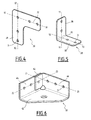
- Each plate 26, illustrated by the figure 4 is a flat part in L.
- the plate 26 has a first branch 32 and a second branch 34.
- the first branch 32 and the second branch 34 each extend along a longitudinal axis, respectively X1-X1 and X2-X2.
- the longitudinal axes X1-X1 and X2-X2 are orthogonal to each other.
- Each square 28, illustrated by the figure 5 comprises a first flat blade 36 and a second flat blade 38.
- the blades 36, 38 of the bracket 28 are joined in an edge 40.
- Each blade 36, 38 of the bracket 28 extends in a plane along a longitudinal axis, respectively Y1-Y1 and Y2-Y2.
- the Y1-Y1 and Y2-Y2 axes are orthogonal between them.
- the planes respectively associated with each of the blades 36, 38 of the bracket 28 are orthogonal.
- Each gusset 30, illustrated by figure 6 comprises a support base 42, a first attachment plate 44 and a second attachment plate 46.
- the base 42 and each plate 44, 46 are flat and each extend in a corresponding plane.
- the planes associated with the base 42 and with each plate 44, 46 are two orthogonal pairs.
- the fixing plates 44, 46 project, relative to the support base 42, on the same side with respect to the plane associated with the support base 42.
- the first attachment plate 44 and the second attachment plate 46 each extend along a longitudinal axis, respectively Z1-Z1 and Z2-Z2.
- the longitudinal axes Z1-Z1 and Z2-Z2 are orthogonal to each other.
- the first fixing plate 44 comprises a tongue 48 protruding at right angles to the plane of the first fixing plate 44 to extend facing the second fixing plate 46, in contact with the face of the second plate 46 which is oriented towards the first fixing plate 44.
- the tongue 48 has a through opening 31 disposed opposite a corresponding through opening 31 of the second fixing plate 46 to accommodate a rivet 8 adapted to pass through the tongue 48 and the second fixing plate 46.
- the face of the base 42 which is opposite to the faces facing each other is called “support surface”.
- the transverse extent of the branches 32, 34 of the plate 26, the blades 36, 38 of the bracket 28 and the fixing plates 44, 46 of the gusset is less than or equal to the width of the faces 24 of the profiled elements 4.
- a first profiled element 4A and a second profiled element 4B of the base 10 and a profiled element 4C of the body 14 of the structure 2 form a wedge 52 of the structure 2.
- first profiled element 4A and the second profiled element 4B of the base comprise two faces 24 oriented towards each other and which define a reception surface 54.
- first profiled element 4A of the base 10 and the profiled element 4C of the body 14 comprise two respective coplanar faces facing outwardly of the structure 2, defining a first external surface 56A of the structure 2.
- the second profiled element 4B of the base and the profiled element 4C of the body 14 comprise two respective faces coplanar and oriented towards the outside of the structure 2, defining a second external surface 56B of the structure 2.
- the profiled elements 4A, 4B, 4C are interconnected by a first bracket 28A, a second bracket 28B, a first plate 26A, a second plate 26 and a gusset 30.
- the first bracket 28A is fixed to the profiled elements 4A and 4C.
- the faces of the blades 36, 38 of the first bracket 28A which are opposite to the faces facing each other are in contact with the wall 16 of the profiled elements 4A, 4C.
- first blade 36 of the first bracket 28A is in contact with the first face 24A of the profiled element 4C of the body 14.
- the second blade 38 of the first bracket 28A is in contact with the face 24 of the first profiled element 4A which is oriented towards the first face 24A of the profiled element 4C.
- the first bracket 28A is applied in abutment against each of said faces 24, 24A.
- the second bracket 28B is fixed to the profiled elements 4B and 4C, similarly to the first bracket 28A.
- first blade 36 of the second bracket 28B is in contact with the second face 24B of the profiled element 4C.
- the second blade 38 of the second bracket 28B is applied in contact with the face 24 of the second profiled element 4B which is oriented towards the second face 24B of the profiled element 4C.
- the second bracket 28B is applied in abutment against each of said faces 24, 24B.
- Each bracket 28 is fixed to the corresponding profiled elements 4 by means of the rivets 8, engaged in the through openings 31 and in corresponding through-openings of the profiled elements 4A, 4B, 4C.
- Each bracket 28 is arranged so that it does not protrude transversely with respect to the corresponding faces 24 of the profiled elements 4.
- One of the faces of the first plate 26A is facing the first outer surface 56A, in contact with the first outer surface 56A.
- the first plate 26A is fixed to the faces 24 of the profiled elements 4A and 4C which define the first external surface 56A. More specifically, the first branch 32 of the first plate 26A is attached to the profiled element 4C. In addition, the second branch 34 of the plate 26A is fixed to the profiled element 4A.
- the second plate 26 is attached to the second outer surface 56B as described above for the first plate 26A.
- one of the faces of the second plate 26B is facing the second outer surface 56B, in contact with the second outer surface 56B.
- the first branch 32 of the second plate 26 is fixed to the profiled element 4B.
- the second branch 34 of the second plate 26 is fixed to the profiled element 4C.
- Each plate 26 is arranged so that it does not protrude transversely with respect to the corresponding faces 24 of the profiled elements 4.
- the gusset 30 is fixed to the profiled elements 4A and 4B.
- the faces of the fixing plates 44, 46 of the gusset 30 which are opposite the faces facing each other are in contact with the receiving surface 54.
- the first plate 44 is facing the face 24 of the profiled element 4A defining the receiving surface 54, in contact with said face 24.
- the second plate 46 is opposite the face 24 of the profiled element 4B defining the receiving surface 54, in contact with said face 24.
- the fixing plates 44, 46 of the gusset 30 are applied in contact with the receiving surface 54, abutting against each of the faces 24 forming the receiving surface 54.
- the gusset 30 is arranged so that the fixing plates 44 46 do not protrude transversely with respect to the faces 24 forming the receiving surface 54.
- the gusset 30 is also arranged so that its support surface is oriented towards the outside of the structure 2.
- the gusset 30 is arranged so that the support base 42 of the gusset 30 does not protrude outwards from the structure 2 with respect to the profiled elements forming the base 10 of the structure 2.
- Each fixing plate 44, 46 is fixed to the corresponding profiled element 4 by means of the rivets 8 engaged in the through openings 31 and in corresponding through-openings of the profiled elements 4A, 4B.
- Each corner 52 is adapted to ensure the attachment of the structure 2 to a carrier part of a railway vehicle, through the support bases 42 of the gussets 30.
- the support surface of the gusset 30 is adapted to be applied in contact with a bearing surface of a railway vehicle, the gusset 30 then being fixed to the bearing surface, for example fixed by rivets.
- a profiled element 4 forms a cross member 58 of the structure 2 between a first profiled element 4M and a second profiled element 4N of the body 14.
- the two profiled elements 4M, 4N of the body 14 extend parallel to each other. Faces 24M, 24N of the profiled elements 4M, 4N, respectively, are facing one another, at a distance from one another. The faces 24M, 24N are parallel to each other.
- the cross member 58 extends orthogonally to the profiled elements 4M, 4N of the body 14.
- the cross member 58 is fixed by each of its end zones 18 to a profiled element 4M, 4N of the body 14. More specifically, the one of the ends 19 of the crossmember 58 is in contact with the face 24M of the profiled element 4M of the body 14. In addition, the other of the ends 19 of the crossmember 58 is in contact with the face 24N of the profiled element 4N of the body 14.
- the three coplanar and outwardly facing faces of the structure 2 of the profiled elements 4M, 4N and the cross member 58 define a surface 56M.
- the profiled elements 4 and the cross member 58 are interconnected by means of two plates 26M, 26N, a third bracket 28M and a fourth bracket 28N.
- the third bracket 28M is fixed to the profiled element 4M and to the crossmember 58. More specifically, the third bracket 28M is fixed to the face 24M of the profiled element 4M of the body 14 and to the face 24 of the crossmember 58 which is oriented towards the face 24M of the profiled element 4M of the body 14, similarly to the brackets 28A, 28B. The bracket 28M is applied in abutment against each of said faces 24, 24M.
- the fourth bracket 28N is fixed to the profiled element 4N and the crossbar 58. More specifically, the fourth bracket 28N is fixed to the face 24N of the profiled element 4N of the body 14 and to the face 24 of the crossbar 58 which is oriented towards the face 24N of the profiled element 4N of the body 14. Preferably, the fourth bracket 28N is disposed, relative to the cross member 58, on the same side as the third bracket 28M. The fourth bracket 28N is applied in abutment against each of said faces 24, 24N.
- Each bracket 28 is arranged so that it does not protrude transversely relative to the corresponding faces 24 of the profiled elements 4 and the crossbar 58.
- the plates 26M, 26N are fixed to the profiled elements 4M, 4N of the body 14 and to the cross member 58 at an external surface 56M of the structure 2.
- the plates 26M, 26N are fixed to the profiled elements 4M, 4N and the cross member 58 in a similar manner to the plates 26 of the corners 52.
- Each plate 26 and each bracket 28 is fixed to the corresponding profiled elements 4 and to crosspiece 58 via rivets 8, engaged in through openings 31 and in corresponding through-openings of profiled elements 4 and crossbar 58.
- the monobloc profiled elements 4 the outer wall 16 of which comes from the same material, of closed and continuous radial section, have higher quadratic moments than the profile elements made by sheet metal bending of the state of the art. gives the structure 2 greater rigidity.
- the profiled elements 4 of the invention have a lesser mass, which leads to structures 2 lighter and less expensive.
- the surface treatment of the profiled elements 4 and the assembly elements 6 ensures electrical continuity between the profiled elements 4 and the assembly elements 6 when they are brought into contact.
Landscapes
- Engineering & Computer Science (AREA)
- Power Engineering (AREA)
- Mechanical Engineering (AREA)
- Automation & Control Theory (AREA)
- Transportation (AREA)
- Connection Of Plates (AREA)
- Body Structure For Vehicles (AREA)
Abstract
Description
- La présente invention concerne une structure pour une installation électrique d'un véhicule ferroviaire, du type comprenant une pluralité d'éléments profilés s'étendant chacun le long d'un axe longitudinal et formant une charpente de la structure, et une pluralité d'éléments d'assemblage des éléments profilés entre eux.
- L'invention s'applique notamment aux structures destinées à recevoir des installations électriques à bord d'un véhicule ferroviaire.
-
EP 2 508 407 B1 décrit une structure pour des installations électriques embarquées à bord d'un véhicule ferroviaire. Une telle structure comprend une pluralité d'éléments profilés reliés entre eux par des éléments d'assemblage. Les éléments profilés et les éléments d'assemblage sont généralement des tôles pliées selon plusieurs axes pour pouvoir être assemblés entre eux afin de former une charpente de la structure. - Toutefois, une telle structure ne donne pas entière satisfaction.
- En effet, une telle structure met en oeuvre des éléments complexes qui en rendent la réalisation et l'installation difficiles, longues et coûteuses.
- Un but de l'invention est de proposer une structure du type précité dont la réalisation et l'installation sont plus simples, plus rapides et moins coûteuses.
- A cet effet, l'invention a pour objet une structure pour une installation électrique d'un véhicule ferroviaire du type précité, dans lequel les éléments profilés sont chacun monobloc en comportant une paroi externe venue d'une même matière, de section radiale fermée et continue.
- En effet, le recours à de tels éléments profilés permet une réalisation rapide, simple et peu coûteuse d'une installation électrique, tout en lui conférant une grande solidité.
- Suivant d'autres aspects avantageux de l'invention, la structure comporte une ou plusieurs des caractéristiques suivantes, prise(s) isolément ou suivant toute combinaison techniquement possible :
- les éléments profilés sont réalisés par extrusion ;
- les éléments profilés sont de section radiale rectangulaire ou carrée ;
- les éléments d'assemblage sont reliés aux éléments profilés par des rivets ;
- chaque élément d'assemblage est fixé à une zone d'extrémité d'un premier élément profilé et à la paroi externe d'un deuxième élément profilé, en contact avec ladite zone d'extrémité et avec ladite paroi externe ;
- au moins un élément d'assemblage est réalisé par pliage d'une tôle plane ;
- trois éléments profilés sont reliés entre eux au niveau de leur zone d'extrémité pour former un coin de la structure, les éléments profilés étant reliés deux à deux entre eux par au moins un élément d'assemblage, au moins l'un des éléments d'assemblage comportant une embase propre à être fixée à une surface porteuse d'un véhicule ferroviaire ;
- les éléments profilés et les éléments d'assemblage sont réalisés dans un matériau conducteur d'électricité, de préférence un métal, notamment de l'aluminium ;
- la pluralité d'éléments d'assemblage est constituée de seulement trois modèles d'éléments d'assemblage distincts, et la structure ne comporte pas d'autres éléments d'assemblage que ces trois modèles ;
- les éléments profilés et les éléments d'assemblage sont traités par un traitement de surface antioxydant.
- En outre, l'invention a pour objet un véhicule ferroviaire comportant au moins une structure telle que définie ci-dessus pour recevoir au moins une installation électrique.
- L'invention sera mieux comprise à l'aide de la description qui va suivre, donnée uniquement à titre d'exemple non limitatif et faite en se référant aux dessins annexés sur lesquels :
- la
figure 1 est une vue en perspective de trois-quarts face d'une structure selon l'invention ; - la
figure 2 est un détail d'un angle de la structure de lafigure 1 ; - la
figure 3 est un détail d'une partie de la structure de lafigure 1 ; - la
figure 4 est une vue en perspective de trois-quarts face d'un premier élément d'assemblage de la structure de lafigure 1 ; - la
figure 5 est une vue en perspective de trois-quarts face d'un deuxième élément d'assemblage de la structure de lafigure 1 ; et - la
figure 6 est une vue en perspective de trois-quarts face d'un troisième élément d'assemblage de la structure de lafigure 1 . - Une structure 2 pour une installation électrique d'un véhicule ferroviaire selon l'invention est représentée sur la
figure 1 . - La structure 2 comporte une pluralité d'éléments profilés 4. La structure 2 comporte en outre une pluralité d'éléments 6 d'assemblage des éléments profilés 4 entre eux. Les éléments d'assemblage 6 maintiennent les éléments profilés 4 par l'intermédiaire de rivets 8. Les éléments profilés 4 sont assemblés entre eux pour former une première base 10, une deuxième base 12, et un corps 14 de la structure 2 reliant les deux bases 10, 12 entre elles.
- Chaque élément profilé 4 comporte une paroi externe 16 et deux zones d'extrémité 18 débouchant chacune sur une extrémité 19 de l'élément profilé 4.
- Avantageusement, les éléments profilés 4 et les éléments d'assemblage 6 sont réalisés dans un matériau conducteur d'électricité, de préférence un métal, par exemple de l'aluminium.
- Dans le cas d'éléments profilés 4 et d'assemblage 6 en aluminium, les éléments profilés 4 et les éléments d'assemblage 6 reçoivent au préalable un traitement de surface antioxydant.
- Chaque élément profilé 4 s'étend le long d'un axe longitudinal propre.
- De préférence, chaque élément profilé 4 est réalisé d'un seul tenant, par exemple réalisé par extrusion. Chaque élément profilé 4 est monobloc. En outre, la paroi externe 16 de chaque élément profilé 4 est venue d'une même matière, de section radiale fermée et continue.
- De préférence, chaque élément profilé 4 est de section carrée ou rectangulaire, comme cela apparaît sur la
figures 1 ,2 et3 . La paroi externe 16 de chaque élément profilé 4 définit quatre faces 24 s'étendant le long de l'axe longitudinal de l'élément profilé 4. - Comme cela apparaît sur ces mêmes figures, les éléments d'assemblage 6 comprennent des plaques 26, des équerres 28 et des goussets 30. Seuls ces trois modèles d'éléments d'assemblage sont utilisés dans la structure 2.
- Chaque élément d'assemblage 6 présente au moins deux ouvertures traversantes 31 débouchant sur chaque des faces de l'élément d'assemblage 6. Chaque ouverture traversante 31 reçoit un rivet 8 de fixation de l'élément d'assemblage 6 à l'élément profilé 4.
- De préférence, chaque élément d'assemblage 6 est réalisé d'un seul tenant. Par exemple, l'équerre 28 et le gousset 30 sont réalisés par pliage d'une tôle.
- Chaque plaque 26, illustrée par la
figure 4 , est une pièce plane en L. - La plaque 26 comporte une première branche 32 et une deuxième branche 34. La première branche 32 et la deuxième branche 34 s'étendent chacune le long d'un axe longitudinal, respectivement X1-X1 et X2-X2. Les axes longitudinaux X1-X1 et X2-X2 sont orthogonaux entre eux.
- Chaque équerre 28, illustrée par la
figure 5 , comprend une première lame 36 plane et une deuxième lame 38 plane. Les lames 36, 38 de l'équerre 28 sont jointives en une arête 40. Chaque lame 36, 38 de l'équerre 28 s'étend dans un plan le long d'un axe longitudinal, respectivement Y1-Y1 et Y2-Y2. Les axes Y1-Y1 et Y2-Y2 sont orthogonaux entre eux. Les plans associés respectivement à chacune des lames 36, 38 de l'équerre 28 sont orthogonaux. - Chaque gousset 30, illustré par la
figure 6 , comporte une embase 42 de support, une première plaque de fixation 44 et une deuxième plaque de fixation 46. L'embase 42 et chaque plaque 44, 46 sont planes et s'étendent chacune dans un plan correspondant. Les plans associés à l'embase 42 et à chaque plaque 44, 46 sont deux à deux orthogonaux. Les plaques de fixation 44, 46 font saillie, par rapport à l'embase de support 42, d'un même côté par rapport au plan associé à l'embase de support 42. - La première plaque de fixation 44 et la deuxième plaque de fixation 46 s'étendent chacune le long d'un axe longitudinal, respectivement Z1-Z1 et Z2-Z2. Les axes longitudinaux Z1-Z1 et Z2-Z2 sont orthogonaux entre eux.
- La première plaque de fixation 44 comporte une languette 48 faisant saillie en équerre par rapport au plan de la première plaque de fixation 44 pour s'étendre en regard de la deuxième plaque de fixation 46, au contact de la face de la deuxième plaque 46 qui est orientée vers la première plaque de fixation 44.
- Avantageusement, la languette 48 comporte une ouverture traversante 31 disposée en regard d'une ouverture traversante 31 correspondante de la deuxième plaque de fixation 46 pour accueillir un rivet 8 propre à traverser la languette 48 et la deuxième plaque de fixation 46.
- La face de l'embase 42 qui est à l'opposé des faces orientées les unes vers les autres est dite « surface de support ».
- L'étendue transversale des branches 32, 34 de la plaque 26, des lames 36, 38 de l'équerre 28 et des plaques de fixation 44, 46 du gousset est inférieure ou égale à la largeur des faces 24 des éléments profilés 4.
- Comme cela apparaît sur la
figure 2 , un premier élément profilé 4A et un deuxième élément profilé 4B de la base 10 et un élément profilé 4C du corps 14 de la structure 2 forment un coin 52 de la structure 2. - En particulier, les deux éléments profilés 4A, 4B de la base 10 sont chacun au contact, par l'une de leurs extrémités 19, d'une même zone d'extrémité 18 de l'élément profilé 4C du corps 14 de la structure 2. Plus précisément :
- l'extrémité 19 du premier élément profilé 4A de la base 10 est au contact d'une première face 24A de l'élément profilé 4C du corps 14, au niveau de sa zone d'extrémité 18 ; et
- l'extrémité 19 du deuxième élément profilé 4B de la base 10 est au contact d'une deuxième face 24B de l'élément profilé 4C du corps 14, au niveau de sa zone d'extrémité 18, la deuxième face 24B étant adjacente à la première face 24A.
- En outre, le premier élément profilé 4A et le deuxième élément profilé 4B de la base comportent deux faces 24 orientées l'une vers l'autre et qui définissent une surface d'accueil 54.
- En outre, le premier élément profilé 4A de la base 10 et l'élément profilé 4C du corps 14 comportent deux faces respectives coplanaires et orientées vers l'extérieur de la structure 2, définissant une première surface externe 56A de la structure 2.
- En outre, le deuxième élément profilé 4B de la base et l'élément profilé 4C du corps 14 comportent deux faces respectives coplanaires et orientées vers l'extérieur de la structure 2, définissant une deuxième surface externe 56B de la structure 2.
- Les éléments profilés 4A, 4B, 4C sont reliés entre eux par une première équerre 28A, une deuxième équerre 28B, une première plaque 26A, une deuxième plaque 26 et un gousset 30.
- La première équerre 28A est fixée aux éléments profilés 4A et 4C. Les faces des lames 36, 38 de la première équerre 28A qui sont à l'opposé des faces orientées l'une vers l'autre sont en contact avec la paroi 16 des éléments profilés 4A, 4C.
- En particulier, la première lame 36 de la première équerre 28A est en contact avec la première face 24A de l'élément profilé 4C du corps 14. La deuxième lame 38 de la première équerre 28A est en contact avec la face 24 du premier élément profilé 4A qui est orientée vers la première face 24A de l'élément profilé 4C. La première équerre 28A est appliquée en butée contre chacune desdites faces 24, 24A.
- En outre, la deuxième équerre 28B est fixée aux éléments profilés 4B et 4C, de manière analogue à la première équerre 28A.
- En particulier, la première lame 36 de la deuxième équerre 28B est en contact avec la deuxième face 24B de l'élément profilé 4C. La deuxième lame 38 de la deuxième équerre 28B est appliquée au contact de la face 24 du deuxième élément profilé 4B qui est orientée vers la deuxième face 24B de l'élément profilé 4C. La deuxième équerre 28B est appliquée en butée contre chacune desdites faces 24, 24B.
- Chaque équerre 28 est fixée aux éléments profilés 4 correspondants par l'intermédiaire des rivets 8, engagés dans les ouvertures traversantes 31 et dans des ouvertures traversantes correspondantes des éléments profilés 4A, 4B, 4C.
- Chaque équerre 28 est disposée de sorte qu'elle ne fasse pas saillie transversalement par rapport aux faces 24 correspondantes des éléments profilés 4.
- L'une des faces de la première plaque 26A est en regard de la première surface externe 56A, en contact avec la première surface externe 56A. La première plaque 26A est fixée aux faces 24 des éléments profilés 4A et 4C qui définissent la première surface externe 56A. Plus précisément, la première branche 32 de la première plaque 26A est fixée à l'élément profilé 4C. En outre, la deuxième branche 34 de la plaque 26A est fixée à l'élément profilé 4A.
- La deuxième plaque 26 est fixée à la deuxième surface externe 56B, comme décrit ci-dessus pour la première plaque 26A. En particulier, l'une des faces de la deuxième plaque 26B est en regard de la deuxième surface externe 56B, en contact avec la deuxième surface externe 56B. La première branche 32 de la deuxième plaque 26 est fixée à l'élément profilé 4B. La deuxième branche 34 de la deuxième plaque 26 est fixée à l'élément profilé 4C.
- Chaque plaque 26 est disposée de sorte qu'elle ne fasse pas saillie transversalement par rapport aux faces 24 correspondantes des éléments profilés 4.
- Le gousset 30 est fixé aux éléments profilés 4A et 4B.
- Les faces des plaques de fixation 44, 46 du gousset 30 qui sont à l'opposé des faces orientées l'une vers l'autre sont en contact avec la surface d'accueil 54. En particulier, la première plaque 44 est en regard de la face 24 de l'élément profilé 4A définissant la surface d'accueil 54, en contact avec ladite face 24. La deuxième plaque 46 est en regard de la face 24 de l'élément profilé 4B définissant la surface d'accueil 54, en contact avec ladite face 24.
- Les plaques de fixation 44, 46 du gousset 30 sont appliquées au contact de la surface d'accueil 54, en butée contre chacune des faces 24 formant la surface d'accueil 54. Le gousset 30 est disposé de sorte que les plaques de fixation 44, 46 ne fassent pas saillies transversalement par rapport aux faces 24 formant la surface d'accueil 54.
- Le gousset 30 est également disposé de sorte que sa surface de support soit orientée vers l'extérieur de la structure 2.
- En outre, le gousset 30 est disposé de sorte que l'embase de support 42 du gousset 30 ne fasse pas saillie vers l'extérieur de la structure 2 par rapport aux éléments profilés formant la base 10 de la structure 2.
- Chaque plaque de fixation 44, 46 est fixée à l'élément profilé 4 correspondant par l'intermédiaire des rivets 8, engagés dans les ouvertures traversantes 31 et dans des ouvertures traversantes correspondantes des éléments profilés 4A, 4B.
- L'agencement décrit ci-dessus pour le coin 52 représenté sur la
figure 2 est répété pour tous les coins de la structure 2. - Chaque coin 52 est propre à assurer la fixation de la structure 2 à une partie porteuse d'un véhicule ferroviaire, par l'intermédiaire des embases de support 42 des goussets 30.
- Notamment, la surface de support du gousset 30 est propre à être appliquée au contact d'une surface porteuse d'un véhicule ferroviaire, le gousset 30 étant alors fixé à la surface porteuse, par exemple fixé par des rivets.
- Comme illustré sur la
figure 3 , un élément profilé 4 forme une traverse 58 de la structure 2 entre un premier élément profilé 4M et un deuxième élément profilé 4N du corps 14. - En particulier, les deux éléments profilés 4M, 4N du corps 14 s'étendent parallèlement l'un à l'autre. Des faces 24M, 24N des éléments profilés 4M, 4N, respectivement, sont en regard l'une de l'autre, à distance l'une de l'autre. Les faces 24M, 24N sont parallèles entre elles.
- La traverse 58 s'étend orthogonalement aux éléments profilés 4M, 4N du corps 14. En outre, la traverse 58 est fixée par chacune de ses zones d'extrémité 18 à un élément profilé 4M, 4N du corps 14. Plus précisément, l'une des extrémités 19 de la traverse 58 est au contact de la face 24M de l'élément profilé 4M du corps 14. En outre, l'autre des extrémités 19 de la traverse 58 est au contact de la face 24N de l'élément profilé 4N du corps 14.
- Les trois faces coplanaires et orientées vers l'extérieur de la structure 2 des éléments profilés 4M, 4N et de la traverse 58 définissent une surface 56M.
- Les éléments profilés 4 et la traverse 58 sont reliés entre eux par l'intermédiaire de de deux plaques 26M, 26N, d'une troisième équerre 28M et d'une quatrième équerre 28N.
- La troisième équerre 28M est fixée à l'élément profilé 4M et à la traverse 58. Plus précisément, la troisième équerre 28M est fixée à la face 24M de l'élément profilé 4M du corps 14 et à la face 24 de la traverse 58 qui est orientée vers la face 24M de l'élément profilé 4M du corps 14, de façon analogue aux équerres 28A, 28B. L'équerre 28M est appliquée en butée contre chacune desdites faces 24, 24M.
- La quatrième équerre 28N est fixée à l'élément profilé 4N et à la traverse 58. Plus précisément, la quatrième équerre 28N est fixée à la face 24N de l'élément profilé 4N du corps 14 et à la face 24 de la traverse 58 qui est orientée vers la face 24N de l'élément profilé 4N du corps 14. De préférence, la quatrième équerre 28N est disposée, par rapport à la traverse 58, du même côté que la troisième équerre 28M. La quatrième équerre 28N est appliquée en butée contre chacune desdites faces 24, 24N.
- Chaque équerre 28 est disposée de façon à ce qu'elle ne fasse pas saillie transversalement par rapport aux faces 24 correspondantes des éléments profilés 4 et de la traverse 58.
- Les plaques 26M, 26N sont fixées aux éléments profilés 4M, 4N du corps 14 et à la traverse 58 au niveau d'une surface externe 56M de la structure 2. Les plaques 26M, 26N sont fixées aux éléments profilés 4M, 4N et à la traverse 58 de manière analogue aux plaques 26 des coins 52.
- Chaque plaque 26 et chaque équerre 28 est fixée aux éléments profilés 4 correspondants et à la traverse 58 par l'intermédiaire des rivets 8, engagés dans les ouvertures traversantes 31 et dans des ouvertures traversantes correspondantes des éléments profilés 4 et de la traverse 58.
- Les éléments profilés 4 monoblocs dont la paroi externe 16 est venue d'une même matière, de section radiale fermée et continue, présentent des moments quadratiques plus élevés que les éléments profilés réalisés par pliage de tôle de l'état de la technique, ce qui confère une plus grande rigidité à la structure 2.
- Pour des moments quadratiques égaux à ceux des éléments profilés de l'état de la technique, les éléments profilés 4 de l'invention présentent une masse moindre, ce qui conduit à des structures 2 plus légères et moins coûteuses.
- En outre, le traitement de surface des éléments profilés 4 et des éléments d'assemblage 6 assure une continuité électrique entre les éléments profilés 4 et les éléments d'assemblage 6 lorsqu'ils sont mis en contact.
Claims (10)
- Structure (2) pour une installation électrique d'un véhicule ferroviaire, du type comprenant une pluralité d'éléments profilés (4) s'étendant chacun le long d'un axe longitudinal et formant une charpente de la structure (2), et une pluralité d'éléments (6) d'assemblage des éléments profilés (4) entre eux, les éléments profilés formant une première base (10), une deuxième base (12) et un corps (14) reliant les deux bases (10, 12) entre elles, la structure (2) étant caractérisée en ce que les éléments profilés (4) sont chacun monobloc en comportant une paroi externe (16) venue d'une même matière, de section radiale fermée et continue,
la structure comprenant au moins un élément profilé formant traverse (58) entre un premier élément profilé (4M) et un deuxième élément profilé (4N), les premier et deuxième éléments profilés (4M, 4N) appartenant au corps,
la pluralité d'éléments d'assemblage (6) étant constituée de seulement trois modèles d'éléments d'assemblage distincts, et la structure (2) ne comportant pas d'autres éléments d'assemblage (6) que ces trois modèles. - Structure (2) selon la revendication 1, caractérisée en ce que les éléments profilés (4) sont réalisés par extrusion.
- Structure (2) selon la revendication 1 ou 2, caractérisée en ce que les éléments profilés (4) sont de section radiale rectangulaire ou carrée.
- Structure (2) selon l'une quelconque des revendications précédentes, caractérisée en ce que les éléments d'assemblage (6) sont reliés aux éléments profilés (4) par des rivets (8).
- Structure (2) selon l'une quelconque des revendications précédentes, caractérisée en ce que chaque élément d'assemblage (6) est fixé à une zone d'extrémité (18) d'un premier élément profilé (4) et à la paroi externe (16) d'un deuxième élément profilé (4), en contact avec ladite zone d'extrémité (18) et avec ladite paroi externe (16).
- Structure (2) selon l'une quelconque des revendications précédentes, caractérisée en ce qu'au moins un élément d'assemblage (6) est réalisé par pliage d'une tôle plane.
- Structure (2) selon l'une quelconque des revendications précédentes, caractérisée en ce que trois éléments profilés (4) sont reliés entre eux au niveau de leur zone d'extrémité (18) pour former un coin (52) de la structure (2), les éléments profilés (4) étant reliés deux à deux entre eux par au moins un élément d'assemblage (6), au moins l'un des éléments d'assemblage (6) comportant une embase (42) propre à être fixée à une surface porteuse d'un véhicule ferroviaire.
- Structure (2) selon l'une quelconque des revendications précédentes, caractérisée en ce que les éléments profilés (4) et les éléments d'assemblage (6) sont réalisés dans un matériau conducteur d'électricité, de préférence un métal, notamment de l'aluminium.
- Structure (2) selon l'une quelconque des revendications précédentes, caractérisée en ce que les éléments profilés (4) et les éléments d'assemblage (6) sont traités par un traitement de surface antioxydant.
- Véhicule ferroviaire, caractérisé en ce qu'il comporte au moins une structure (2) selon l'une quelconque des revendications précédentes pour recevoir au moins une installation électrique.
Applications Claiming Priority (1)
| Application Number | Priority Date | Filing Date | Title |
|---|---|---|---|
| FR1458302A FR3025478B1 (fr) | 2014-09-04 | 2014-09-04 | Structure pour une installation electrique d'un vehicule ferroviaire et vehicule ferroviaire associe. |
Publications (2)
| Publication Number | Publication Date |
|---|---|
| EP2993745A1 true EP2993745A1 (fr) | 2016-03-09 |
| EP2993745B1 EP2993745B1 (fr) | 2020-11-11 |
Family
ID=51987312
Family Applications (1)
| Application Number | Title | Priority Date | Filing Date |
|---|---|---|---|
| EP15182211.1A Active EP2993745B1 (fr) | 2014-09-04 | 2015-08-24 | Structure pour une installation électrique d'un véhicule ferroviaire et véhicule ferroviaire associé |
Country Status (4)
| Country | Link |
|---|---|
| EP (1) | EP2993745B1 (fr) |
| CN (1) | CN105398456B (fr) |
| FR (1) | FR3025478B1 (fr) |
| RU (1) | RU2690836C2 (fr) |
Cited By (4)
| Publication number | Priority date | Publication date | Assignee | Title |
|---|---|---|---|---|
| GB2550920A (en) * | 2016-05-31 | 2017-12-06 | Bombardier Transp Gmbh | Cubicle and rail vehicle comprising a cubicle |
| CN108146842A (zh) * | 2017-12-07 | 2018-06-12 | 天津华迈燃气装备股份有限公司 | 一种用于加液设备的仪表框架装置 |
| KR20190001060U (ko) * | 2017-10-25 | 2019-05-07 | 선도전기주식회사 | 수배전반용 프레임 연결 브래킷 |
| CN111795041A (zh) * | 2019-04-04 | 2020-10-20 | 迪尔公司 | 用于矩形管拐角应力释放的通用铸件 |
Families Citing this family (3)
| Publication number | Priority date | Publication date | Assignee | Title |
|---|---|---|---|---|
| CN105909966A (zh) * | 2016-06-03 | 2016-08-31 | 广州途道信息科技有限公司 | 一种结构件 |
| CN106864599A (zh) * | 2017-04-02 | 2017-06-20 | 苏州安耐驰汽车科技有限公司 | 一种汽车模块化骨架组件 |
| CN114559975B (zh) * | 2022-03-08 | 2023-08-08 | 中车青岛四方机车车辆股份有限公司 | 一种模块化设备吊挂框架及磁浮车辆 |
Citations (3)
| Publication number | Priority date | Publication date | Assignee | Title |
|---|---|---|---|---|
| DE29712998U1 (de) * | 1997-07-22 | 1997-09-18 | Knürr-Mechanik für die Elektronik AG., 81829 München | Eckverbinder |
| US20040036389A1 (en) * | 2002-08-21 | 2004-02-26 | Chiang-Hai Tsai | Extruded aluminum computer case structure with connecting sheets |
| EP2508407A1 (fr) * | 2011-04-04 | 2012-10-10 | Bombardier Transportation GmbH | Structure, en particulier pour les installations électriques dans un véhicule sur rail, et procédé de fabrication de cette structure |
Family Cites Families (14)
| Publication number | Priority date | Publication date | Assignee | Title |
|---|---|---|---|---|
| DE2515569B2 (de) * | 1975-04-10 | 1978-02-16 | Veyhl-Produktion KG, 7261 Zwerenberg | Verbindung fuer drei rohrabschnitte |
| DE2654239A1 (de) * | 1976-11-30 | 1978-06-01 | Licentia Gmbh | Schaltschrank mit einem aus profilstaeben hergestellten geruest |
| DE9212031U1 (de) * | 1992-09-07 | 1994-01-13 | Skeppner, Hans, Brüssel | Schaltschrank |
| JP4129945B2 (ja) * | 2001-09-06 | 2008-08-06 | 日東工業株式会社 | 電気電子機器収納用キャビネットのフレーム結合構造 |
| CN1185432C (zh) * | 2002-04-09 | 2005-01-19 | 上海惠亚电子有限公司 | 一种装配式的机柜框架结构 |
| CN201118100Y (zh) * | 2006-11-28 | 2008-09-17 | 正泰电气股份有限公司 | 一种角部连接装置 |
| BRPI0701427A2 (pt) * | 2007-04-11 | 2008-11-25 | Melquisedec Francisquini | aperfeiÇoamento em painel elÉtrico |
| CN201623370U (zh) * | 2009-12-14 | 2010-11-03 | 赵红梅 | 一种低压动力配电柜的框架 |
| CN201750052U (zh) * | 2010-08-06 | 2011-02-16 | 上海一开电气集团有限公司 | 低压开关柜壳体装配的梁柱固定连接部件 |
| TR201007656A2 (tr) * | 2010-09-20 | 2012-04-24 | Kiraç Metal Ürünleri̇ San. Ve Ti̇c. Ltd. Şti̇ | Elektrik panosu yapılarında yenilik |
| CN201946878U (zh) * | 2010-12-30 | 2011-08-24 | 南京大全电气有限公司 | 落地配电箱框架连接件 |
| CN202405622U (zh) * | 2011-12-29 | 2012-08-29 | 湖南省西点电力设备有限责任公司 | 一种组合式配电柜柜架 |
| CN202474571U (zh) * | 2012-02-29 | 2012-10-03 | 宁波海越电器制造有限公司 | 一种低压开关框架 |
| RU133471U1 (ru) * | 2012-11-21 | 2013-10-20 | Общество с ограниченной ответственностью "Уральские локомотивы" | Блок аппаратов электровоза |
-
2014
- 2014-09-04 FR FR1458302A patent/FR3025478B1/fr not_active Expired - Fee Related
-
2015
- 2015-08-24 EP EP15182211.1A patent/EP2993745B1/fr active Active
- 2015-09-03 RU RU2015137700A patent/RU2690836C2/ru active
- 2015-09-06 CN CN201510559869.4A patent/CN105398456B/zh active Active
Patent Citations (4)
| Publication number | Priority date | Publication date | Assignee | Title |
|---|---|---|---|---|
| DE29712998U1 (de) * | 1997-07-22 | 1997-09-18 | Knürr-Mechanik für die Elektronik AG., 81829 München | Eckverbinder |
| US20040036389A1 (en) * | 2002-08-21 | 2004-02-26 | Chiang-Hai Tsai | Extruded aluminum computer case structure with connecting sheets |
| EP2508407A1 (fr) * | 2011-04-04 | 2012-10-10 | Bombardier Transportation GmbH | Structure, en particulier pour les installations électriques dans un véhicule sur rail, et procédé de fabrication de cette structure |
| EP2508407B1 (fr) | 2011-04-04 | 2013-04-24 | Bombardier Transportation GmbH | Structure, en particulier pour les installations électriques dans un véhicule sur rail, et procédé de fabrication de cette structure |
Cited By (6)
| Publication number | Priority date | Publication date | Assignee | Title |
|---|---|---|---|---|
| GB2550920A (en) * | 2016-05-31 | 2017-12-06 | Bombardier Transp Gmbh | Cubicle and rail vehicle comprising a cubicle |
| EP3252892B1 (fr) * | 2016-05-31 | 2021-07-28 | Bombardier Transportation GmbH | Véhicule ferroviaire équipé d'une armoire |
| KR20190001060U (ko) * | 2017-10-25 | 2019-05-07 | 선도전기주식회사 | 수배전반용 프레임 연결 브래킷 |
| CN108146842A (zh) * | 2017-12-07 | 2018-06-12 | 天津华迈燃气装备股份有限公司 | 一种用于加液设备的仪表框架装置 |
| CN111795041A (zh) * | 2019-04-04 | 2020-10-20 | 迪尔公司 | 用于矩形管拐角应力释放的通用铸件 |
| CN111795041B (zh) * | 2019-04-04 | 2024-03-22 | 迪尔公司 | 用于矩形管拐角应力释放的通用铸件 |
Also Published As
| Publication number | Publication date |
|---|---|
| RU2015137700A3 (fr) | 2019-04-03 |
| RU2015137700A (ru) | 2017-03-06 |
| FR3025478B1 (fr) | 2018-02-16 |
| RU2690836C2 (ru) | 2019-06-05 |
| CN105398456A (zh) | 2016-03-16 |
| EP2993745B1 (fr) | 2020-11-11 |
| FR3025478A1 (fr) | 2016-03-11 |
| CN105398456B (zh) | 2020-02-07 |
Similar Documents
| Publication | Publication Date | Title |
|---|---|---|
| EP2993745B1 (fr) | Structure pour une installation électrique d'un véhicule ferroviaire et véhicule ferroviaire associé | |
| EP3494315A1 (fr) | Agrafe de maintien de deux elements plans | |
| EP3096999B1 (fr) | Structure de caisse d'un véhicule automobile avec renforts de répartition des efforts liés à un amortisseur arrière du véhicule | |
| EP4015842A1 (fr) | Agrafe de maintien de deux elements plans, assemblage comprenant une telle agrafe | |
| FR3018960A1 (fr) | Element d'accouplement pour troncons de chemin de cables en treillis metallique, et troncon de chemin de cables en treillis metallique | |
| EP3995045A1 (fr) | Table à rallonge centrale | |
| EP3217025A1 (fr) | Ensemble de guidage et fixation comportant un système de fixation permanente d'un premier panneau à un deuxième panneau adjacent et une charnière, meuble comportant un tel ensemble et procédé de montage d'un tel meuble | |
| FR3025503A1 (fr) | Ensemble de construction pour pylone d’ascenseur et pylone d’ascenseur associe | |
| EP1283124B1 (fr) | Système pour la fixation d'un siège sur un plancher de véhicule | |
| FR3072109A1 (fr) | Systeme de cloture, comprenant au moins un panneau treillis et au moins une lame occultante | |
| FR3064508B1 (fr) | Dispositif de liaison entre deux toles metalliques | |
| EP0985834B1 (fr) | Dispositif de fixation d'au moins une pièce sur une autre pièce, en forme de plaque | |
| EP3319188A1 (fr) | Système d'assemblage d'armoires électriques d'un tableau électrique | |
| EP3483993A1 (fr) | Socle pour armoire electrique | |
| EP3115624B1 (fr) | Dispositif de liaison amovible d'au moins deux profiles croises | |
| EP3748097B1 (fr) | Ossature métallique pour panneaux de cloison sèche en préfabriqué | |
| FR3082273A1 (fr) | Cadre notamment destine a la fabrication d'un panneau et rehausse avec un tel cadre | |
| FR2970017A1 (fr) | Dispositif pour l'assemblage d'une marche sur un support | |
| EP0599743B1 (fr) | Dispositif de support pour appareillage électrique modulaire | |
| EP3074641B1 (fr) | Assemblage avec guidage d'une levre mince allongee dans une fente etroite allongee et application a l'assemblage d'un guide-air sur une buse | |
| FR3063100A1 (fr) | Systeme d'assemblage entre eux de deux profiles pour une menuiserie du type porte ou fenetre | |
| BE1018976A3 (fr) | Structure rigide tridimensionnelle modulaire. | |
| FR3018101A1 (fr) | Piece de jonction pour table pliante | |
| EP4008608A1 (fr) | Véhicule doté d'un châssis arrière destiné à soutenir un dispositif de chargement | |
| FR2959556A1 (fr) | Panneau solaire parallelepipedique avec support pour la pose sur une structure de reception |
Legal Events
| Date | Code | Title | Description |
|---|---|---|---|
| PUAI | Public reference made under article 153(3) epc to a published international application that has entered the european phase |
Free format text: ORIGINAL CODE: 0009012 |
|
| AK | Designated contracting states |
Kind code of ref document: A1 Designated state(s): AL AT BE BG CH CY CZ DE DK EE ES FI FR GB GR HR HU IE IS IT LI LT LU LV MC MK MT NL NO PL PT RO RS SE SI SK SM TR |
|
| AX | Request for extension of the european patent |
Extension state: BA ME |
|
| RAP1 | Party data changed (applicant data changed or rights of an application transferred) |
Owner name: ALSTOM TRANSPORT TECHNOLOGIES |
|
| 17P | Request for examination filed |
Effective date: 20160909 |
|
| RBV | Designated contracting states (corrected) |
Designated state(s): AL AT BE BG CH CY CZ DE DK EE ES FI FR GB GR HR HU IE IS IT LI LT LU LV MC MK MT NL NO PL PT RO RS SE SI SK SM TR |
|
| RIC1 | Information provided on ipc code assigned before grant |
Ipc: H02B 1/01 20060101AFI20180928BHEP |
|
| STAA | Information on the status of an ep patent application or granted ep patent |
Free format text: STATUS: EXAMINATION IS IN PROGRESS |
|
| 17Q | First examination report despatched |
Effective date: 20181121 |
|
| GRAP | Despatch of communication of intention to grant a patent |
Free format text: ORIGINAL CODE: EPIDOSNIGR1 |
|
| STAA | Information on the status of an ep patent application or granted ep patent |
Free format text: STATUS: GRANT OF PATENT IS INTENDED |
|
| RIC1 | Information provided on ipc code assigned before grant |
Ipc: F16B 7/18 20060101ALN20200511BHEP Ipc: H02B 1/01 20060101ALI20200511BHEP Ipc: F16B 7/04 20060101AFI20200511BHEP |
|
| RIC1 | Information provided on ipc code assigned before grant |
Ipc: F16B 7/04 20060101AFI20200518BHEP Ipc: F16B 7/18 20060101ALN20200518BHEP Ipc: H02B 1/01 20060101ALI20200518BHEP |
|
| INTG | Intention to grant announced |
Effective date: 20200616 |
|
| REG | Reference to a national code |
Ref country code: DE Ref legal event code: R079 Ref document number: 602015061788 Country of ref document: DE Free format text: PREVIOUS MAIN CLASS: H02B0001010000 Ipc: F16B0007040000 |
|
| GRAJ | Information related to disapproval of communication of intention to grant by the applicant or resumption of examination proceedings by the epo deleted |
Free format text: ORIGINAL CODE: EPIDOSDIGR1 |
|
| STAA | Information on the status of an ep patent application or granted ep patent |
Free format text: STATUS: EXAMINATION IS IN PROGRESS |
|
| GRAR | Information related to intention to grant a patent recorded |
Free format text: ORIGINAL CODE: EPIDOSNIGR71 |
|
| GRAS | Grant fee paid |
Free format text: ORIGINAL CODE: EPIDOSNIGR3 |
|
| STAA | Information on the status of an ep patent application or granted ep patent |
Free format text: STATUS: GRANT OF PATENT IS INTENDED |
|
| GRAA | (expected) grant |
Free format text: ORIGINAL CODE: 0009210 |
|
| STAA | Information on the status of an ep patent application or granted ep patent |
Free format text: STATUS: THE PATENT HAS BEEN GRANTED |
|
| INTC | Intention to grant announced (deleted) | ||
| RIC1 | Information provided on ipc code assigned before grant |
Ipc: F16B 7/04 20060101AFI20200924BHEP Ipc: F16B 7/18 20060101ALN20200924BHEP Ipc: H02B 1/01 20060101ALI20200924BHEP |
|
| AK | Designated contracting states |
Kind code of ref document: B1 Designated state(s): AL AT BE BG CH CY CZ DE DK EE ES FI FR GB GR HR HU IE IS IT LI LT LU LV MC MK MT NL NO PL PT RO RS SE SI SK SM TR |
|
| INTG | Intention to grant announced |
Effective date: 20201002 |
|
| REG | Reference to a national code |
Ref country code: GB Ref legal event code: FG4D Free format text: NOT ENGLISH |
|
| REG | Reference to a national code |
Ref country code: CH Ref legal event code: EP |
|
| REG | Reference to a national code |
Ref country code: AT Ref legal event code: REF Ref document number: 1333750 Country of ref document: AT Kind code of ref document: T Effective date: 20201115 |
|
| REG | Reference to a national code |
Ref country code: DE Ref legal event code: R096 Ref document number: 602015061788 Country of ref document: DE |
|
| REG | Reference to a national code |
Ref country code: IE Ref legal event code: FG4D Free format text: LANGUAGE OF EP DOCUMENT: FRENCH |
|
| REG | Reference to a national code |
Ref country code: DE Ref legal event code: R082 Ref document number: 602015061788 Country of ref document: DE Representative=s name: WR SERVICES GMBH, DE |
|
| REG | Reference to a national code |
Ref country code: NL Ref legal event code: MP Effective date: 20201111 |
|
| REG | Reference to a national code |
Ref country code: AT Ref legal event code: MK05 Ref document number: 1333750 Country of ref document: AT Kind code of ref document: T Effective date: 20201111 |
|
| PG25 | Lapsed in a contracting state [announced via postgrant information from national office to epo] |
Ref country code: RS Free format text: LAPSE BECAUSE OF FAILURE TO SUBMIT A TRANSLATION OF THE DESCRIPTION OR TO PAY THE FEE WITHIN THE PRESCRIBED TIME-LIMIT Effective date: 20201111 Ref country code: FI Free format text: LAPSE BECAUSE OF FAILURE TO SUBMIT A TRANSLATION OF THE DESCRIPTION OR TO PAY THE FEE WITHIN THE PRESCRIBED TIME-LIMIT Effective date: 20201111 Ref country code: NO Free format text: LAPSE BECAUSE OF FAILURE TO SUBMIT A TRANSLATION OF THE DESCRIPTION OR TO PAY THE FEE WITHIN THE PRESCRIBED TIME-LIMIT Effective date: 20210211 Ref country code: PT Free format text: LAPSE BECAUSE OF FAILURE TO SUBMIT A TRANSLATION OF THE DESCRIPTION OR TO PAY THE FEE WITHIN THE PRESCRIBED TIME-LIMIT Effective date: 20210311 Ref country code: GR Free format text: LAPSE BECAUSE OF FAILURE TO SUBMIT A TRANSLATION OF THE DESCRIPTION OR TO PAY THE FEE WITHIN THE PRESCRIBED TIME-LIMIT Effective date: 20210212 |
|
| PG25 | Lapsed in a contracting state [announced via postgrant information from national office to epo] |
Ref country code: LV Free format text: LAPSE BECAUSE OF FAILURE TO SUBMIT A TRANSLATION OF THE DESCRIPTION OR TO PAY THE FEE WITHIN THE PRESCRIBED TIME-LIMIT Effective date: 20201111 Ref country code: PL Free format text: LAPSE BECAUSE OF FAILURE TO SUBMIT A TRANSLATION OF THE DESCRIPTION OR TO PAY THE FEE WITHIN THE PRESCRIBED TIME-LIMIT Effective date: 20201111 Ref country code: IS Free format text: LAPSE BECAUSE OF FAILURE TO SUBMIT A TRANSLATION OF THE DESCRIPTION OR TO PAY THE FEE WITHIN THE PRESCRIBED TIME-LIMIT Effective date: 20210311 Ref country code: SE Free format text: LAPSE BECAUSE OF FAILURE TO SUBMIT A TRANSLATION OF THE DESCRIPTION OR TO PAY THE FEE WITHIN THE PRESCRIBED TIME-LIMIT Effective date: 20201111 Ref country code: BG Free format text: LAPSE BECAUSE OF FAILURE TO SUBMIT A TRANSLATION OF THE DESCRIPTION OR TO PAY THE FEE WITHIN THE PRESCRIBED TIME-LIMIT Effective date: 20210211 Ref country code: AT Free format text: LAPSE BECAUSE OF FAILURE TO SUBMIT A TRANSLATION OF THE DESCRIPTION OR TO PAY THE FEE WITHIN THE PRESCRIBED TIME-LIMIT Effective date: 20201111 |
|
| REG | Reference to a national code |
Ref country code: LT Ref legal event code: MG9D |
|
| PG25 | Lapsed in a contracting state [announced via postgrant information from national office to epo] |
Ref country code: HR Free format text: LAPSE BECAUSE OF FAILURE TO SUBMIT A TRANSLATION OF THE DESCRIPTION OR TO PAY THE FEE WITHIN THE PRESCRIBED TIME-LIMIT Effective date: 20201111 |
|
| PG25 | Lapsed in a contracting state [announced via postgrant information from national office to epo] |
Ref country code: SK Free format text: LAPSE BECAUSE OF FAILURE TO SUBMIT A TRANSLATION OF THE DESCRIPTION OR TO PAY THE FEE WITHIN THE PRESCRIBED TIME-LIMIT Effective date: 20201111 Ref country code: RO Free format text: LAPSE BECAUSE OF FAILURE TO SUBMIT A TRANSLATION OF THE DESCRIPTION OR TO PAY THE FEE WITHIN THE PRESCRIBED TIME-LIMIT Effective date: 20201111 Ref country code: LT Free format text: LAPSE BECAUSE OF FAILURE TO SUBMIT A TRANSLATION OF THE DESCRIPTION OR TO PAY THE FEE WITHIN THE PRESCRIBED TIME-LIMIT Effective date: 20201111 Ref country code: CZ Free format text: LAPSE BECAUSE OF FAILURE TO SUBMIT A TRANSLATION OF THE DESCRIPTION OR TO PAY THE FEE WITHIN THE PRESCRIBED TIME-LIMIT Effective date: 20201111 Ref country code: EE Free format text: LAPSE BECAUSE OF FAILURE TO SUBMIT A TRANSLATION OF THE DESCRIPTION OR TO PAY THE FEE WITHIN THE PRESCRIBED TIME-LIMIT Effective date: 20201111 Ref country code: SM Free format text: LAPSE BECAUSE OF FAILURE TO SUBMIT A TRANSLATION OF THE DESCRIPTION OR TO PAY THE FEE WITHIN THE PRESCRIBED TIME-LIMIT Effective date: 20201111 |
|
| REG | Reference to a national code |
Ref country code: DE Ref legal event code: R097 Ref document number: 602015061788 Country of ref document: DE |
|
| PG25 | Lapsed in a contracting state [announced via postgrant information from national office to epo] |
Ref country code: DK Free format text: LAPSE BECAUSE OF FAILURE TO SUBMIT A TRANSLATION OF THE DESCRIPTION OR TO PAY THE FEE WITHIN THE PRESCRIBED TIME-LIMIT Effective date: 20201111 |
|
| PLBE | No opposition filed within time limit |
Free format text: ORIGINAL CODE: 0009261 |
|
| STAA | Information on the status of an ep patent application or granted ep patent |
Free format text: STATUS: NO OPPOSITION FILED WITHIN TIME LIMIT |
|
| 26N | No opposition filed |
Effective date: 20210812 |
|
| PG25 | Lapsed in a contracting state [announced via postgrant information from national office to epo] |
Ref country code: NL Free format text: LAPSE BECAUSE OF FAILURE TO SUBMIT A TRANSLATION OF THE DESCRIPTION OR TO PAY THE FEE WITHIN THE PRESCRIBED TIME-LIMIT Effective date: 20201111 Ref country code: AL Free format text: LAPSE BECAUSE OF FAILURE TO SUBMIT A TRANSLATION OF THE DESCRIPTION OR TO PAY THE FEE WITHIN THE PRESCRIBED TIME-LIMIT Effective date: 20201111 Ref country code: IT Free format text: LAPSE BECAUSE OF FAILURE TO SUBMIT A TRANSLATION OF THE DESCRIPTION OR TO PAY THE FEE WITHIN THE PRESCRIBED TIME-LIMIT Effective date: 20201111 |
|
| PG25 | Lapsed in a contracting state [announced via postgrant information from national office to epo] |
Ref country code: ES Free format text: LAPSE BECAUSE OF FAILURE TO SUBMIT A TRANSLATION OF THE DESCRIPTION OR TO PAY THE FEE WITHIN THE PRESCRIBED TIME-LIMIT Effective date: 20201111 Ref country code: SI Free format text: LAPSE BECAUSE OF FAILURE TO SUBMIT A TRANSLATION OF THE DESCRIPTION OR TO PAY THE FEE WITHIN THE PRESCRIBED TIME-LIMIT Effective date: 20201111 |
|
| REG | Reference to a national code |
Ref country code: CH Ref legal event code: PL |
|
| PG25 | Lapsed in a contracting state [announced via postgrant information from national office to epo] |
Ref country code: MC Free format text: LAPSE BECAUSE OF FAILURE TO SUBMIT A TRANSLATION OF THE DESCRIPTION OR TO PAY THE FEE WITHIN THE PRESCRIBED TIME-LIMIT Effective date: 20201111 |
|
| REG | Reference to a national code |
Ref country code: BE Ref legal event code: MM Effective date: 20210831 |
|
| GBPC | Gb: european patent ceased through non-payment of renewal fee |
Effective date: 20210824 |
|
| PG25 | Lapsed in a contracting state [announced via postgrant information from national office to epo] |
Ref country code: LI Free format text: LAPSE BECAUSE OF NON-PAYMENT OF DUE FEES Effective date: 20210831 Ref country code: CH Free format text: LAPSE BECAUSE OF NON-PAYMENT OF DUE FEES Effective date: 20210831 |
|
| PG25 | Lapsed in a contracting state [announced via postgrant information from national office to epo] |
Ref country code: IS Free format text: LAPSE BECAUSE OF FAILURE TO SUBMIT A TRANSLATION OF THE DESCRIPTION OR TO PAY THE FEE WITHIN THE PRESCRIBED TIME-LIMIT Effective date: 20210311 Ref country code: LU Free format text: LAPSE BECAUSE OF NON-PAYMENT OF DUE FEES Effective date: 20210824 |
|
| PG25 | Lapsed in a contracting state [announced via postgrant information from national office to epo] |
Ref country code: IE Free format text: LAPSE BECAUSE OF NON-PAYMENT OF DUE FEES Effective date: 20210824 Ref country code: GB Free format text: LAPSE BECAUSE OF NON-PAYMENT OF DUE FEES Effective date: 20210824 Ref country code: BE Free format text: LAPSE BECAUSE OF NON-PAYMENT OF DUE FEES Effective date: 20210831 |
|
| PG25 | Lapsed in a contracting state [announced via postgrant information from national office to epo] |
Ref country code: HU Free format text: LAPSE BECAUSE OF FAILURE TO SUBMIT A TRANSLATION OF THE DESCRIPTION OR TO PAY THE FEE WITHIN THE PRESCRIBED TIME-LIMIT; INVALID AB INITIO Effective date: 20150824 |
|
| PG25 | Lapsed in a contracting state [announced via postgrant information from national office to epo] |
Ref country code: CY Free format text: LAPSE BECAUSE OF FAILURE TO SUBMIT A TRANSLATION OF THE DESCRIPTION OR TO PAY THE FEE WITHIN THE PRESCRIBED TIME-LIMIT Effective date: 20201111 |
|
| P01 | Opt-out of the competence of the unified patent court (upc) registered |
Effective date: 20230823 |
|
| PG25 | Lapsed in a contracting state [announced via postgrant information from national office to epo] |
Ref country code: MK Free format text: LAPSE BECAUSE OF FAILURE TO SUBMIT A TRANSLATION OF THE DESCRIPTION OR TO PAY THE FEE WITHIN THE PRESCRIBED TIME-LIMIT Effective date: 20201111 |
|
| PG25 | Lapsed in a contracting state [announced via postgrant information from national office to epo] |
Ref country code: MT Free format text: LAPSE BECAUSE OF FAILURE TO SUBMIT A TRANSLATION OF THE DESCRIPTION OR TO PAY THE FEE WITHIN THE PRESCRIBED TIME-LIMIT Effective date: 20201111 |
|
| PGFP | Annual fee paid to national office [announced via postgrant information from national office to epo] |
Ref country code: DE Payment date: 20250820 Year of fee payment: 11 |
|
| PGFP | Annual fee paid to national office [announced via postgrant information from national office to epo] |
Ref country code: TR Payment date: 20250818 Year of fee payment: 11 |
|
| PGFP | Annual fee paid to national office [announced via postgrant information from national office to epo] |
Ref country code: FR Payment date: 20250829 Year of fee payment: 11 |