EP2993470A1 - Ultrasonic inspection of composite parts - Google Patents
Ultrasonic inspection of composite parts Download PDFInfo
- Publication number
- EP2993470A1 EP2993470A1 EP14189245.5A EP14189245A EP2993470A1 EP 2993470 A1 EP2993470 A1 EP 2993470A1 EP 14189245 A EP14189245 A EP 14189245A EP 2993470 A1 EP2993470 A1 EP 2993470A1
- Authority
- EP
- European Patent Office
- Prior art keywords
- component
- probe array
- ultrasonic
- ultrasonic probe
- portions
- Prior art date
- Legal status (The legal status is an assumption and is not a legal conclusion. Google has not performed a legal analysis and makes no representation as to the accuracy of the status listed.)
- Granted
Links
Images



Classifications
-
- G—PHYSICS
- G01—MEASURING; TESTING
- G01M—TESTING STATIC OR DYNAMIC BALANCE OF MACHINES OR STRUCTURES; TESTING OF STRUCTURES OR APPARATUS, NOT OTHERWISE PROVIDED FOR
- G01M13/00—Testing of machine parts
-
- G—PHYSICS
- G01—MEASURING; TESTING
- G01N—INVESTIGATING OR ANALYSING MATERIALS BY DETERMINING THEIR CHEMICAL OR PHYSICAL PROPERTIES
- G01N29/00—Investigating or analysing materials by the use of ultrasonic, sonic or infrasonic waves; Visualisation of the interior of objects by transmitting ultrasonic or sonic waves through the object
- G01N29/04—Analysing solids
-
- G—PHYSICS
- G01—MEASURING; TESTING
- G01N—INVESTIGATING OR ANALYSING MATERIALS BY DETERMINING THEIR CHEMICAL OR PHYSICAL PROPERTIES
- G01N29/00—Investigating or analysing materials by the use of ultrasonic, sonic or infrasonic waves; Visualisation of the interior of objects by transmitting ultrasonic or sonic waves through the object
- G01N29/22—Details, e.g. general constructional or apparatus details
- G01N29/221—Arrangements for directing or focusing the acoustical waves
-
- G—PHYSICS
- G01—MEASURING; TESTING
- G01N—INVESTIGATING OR ANALYSING MATERIALS BY DETERMINING THEIR CHEMICAL OR PHYSICAL PROPERTIES
- G01N29/00—Investigating or analysing materials by the use of ultrasonic, sonic or infrasonic waves; Visualisation of the interior of objects by transmitting ultrasonic or sonic waves through the object
- G01N29/22—Details, e.g. general constructional or apparatus details
- G01N29/225—Supports, positioning or alignment in moving situation
-
- G—PHYSICS
- G01—MEASURING; TESTING
- G01N—INVESTIGATING OR ANALYSING MATERIALS BY DETERMINING THEIR CHEMICAL OR PHYSICAL PROPERTIES
- G01N29/00—Investigating or analysing materials by the use of ultrasonic, sonic or infrasonic waves; Visualisation of the interior of objects by transmitting ultrasonic or sonic waves through the object
- G01N29/22—Details, e.g. general constructional or apparatus details
- G01N29/24—Probes
-
- G—PHYSICS
- G01—MEASURING; TESTING
- G01N—INVESTIGATING OR ANALYSING MATERIALS BY DETERMINING THEIR CHEMICAL OR PHYSICAL PROPERTIES
- G01N29/00—Investigating or analysing materials by the use of ultrasonic, sonic or infrasonic waves; Visualisation of the interior of objects by transmitting ultrasonic or sonic waves through the object
- G01N29/34—Generating the ultrasonic, sonic or infrasonic waves, e.g. electronic circuits specially adapted therefor
- G01N29/341—Generating the ultrasonic, sonic or infrasonic waves, e.g. electronic circuits specially adapted therefor with time characteristics
-
- G—PHYSICS
- G01—MEASURING; TESTING
- G01N—INVESTIGATING OR ANALYSING MATERIALS BY DETERMINING THEIR CHEMICAL OR PHYSICAL PROPERTIES
- G01N2291/00—Indexing codes associated with group G01N29/00
- G01N2291/02—Indexing codes associated with the analysed material
- G01N2291/023—Solids
-
- G—PHYSICS
- G01—MEASURING; TESTING
- G01N—INVESTIGATING OR ANALYSING MATERIALS BY DETERMINING THEIR CHEMICAL OR PHYSICAL PROPERTIES
- G01N2291/00—Indexing codes associated with group G01N29/00
- G01N2291/02—Indexing codes associated with the analysed material
- G01N2291/023—Solids
- G01N2291/0231—Composite or layered materials
-
- G—PHYSICS
- G01—MEASURING; TESTING
- G01N—INVESTIGATING OR ANALYSING MATERIALS BY DETERMINING THEIR CHEMICAL OR PHYSICAL PROPERTIES
- G01N2291/00—Indexing codes associated with group G01N29/00
- G01N2291/02—Indexing codes associated with the analysed material
- G01N2291/028—Material parameters
- G01N2291/0289—Internal structure, e.g. defects, grain size, texture
-
- G—PHYSICS
- G01—MEASURING; TESTING
- G01N—INVESTIGATING OR ANALYSING MATERIALS BY DETERMINING THEIR CHEMICAL OR PHYSICAL PROPERTIES
- G01N2291/00—Indexing codes associated with group G01N29/00
- G01N2291/10—Number of transducers
- G01N2291/106—Number of transducers one or more transducer arrays
-
- G—PHYSICS
- G01—MEASURING; TESTING
- G01N—INVESTIGATING OR ANALYSING MATERIALS BY DETERMINING THEIR CHEMICAL OR PHYSICAL PROPERTIES
- G01N2291/00—Indexing codes associated with group G01N29/00
- G01N2291/26—Scanned objects
- G01N2291/263—Surfaces
- G01N2291/2638—Complex surfaces
-
- G—PHYSICS
- G01—MEASURING; TESTING
- G01N—INVESTIGATING OR ANALYSING MATERIALS BY DETERMINING THEIR CHEMICAL OR PHYSICAL PROPERTIES
- G01N2291/00—Indexing codes associated with group G01N29/00
- G01N2291/26—Scanned objects
- G01N2291/269—Various geometry objects
- G01N2291/2694—Wings or other aircraft parts
Definitions
- This disclosure relates to the ultrasonic inspection of parts, e.g., composite components for an aircraft.
- components are inspected for defects before installation.
- the components can be inspected using ultrasonic techniques.
- composite components for use in an aircraft can be inspected for defects using an ultrasonic probe.
- Some components are large or have multiple surfaces that can increase the amount of time needed for a thorough ultrasonic inspection.
- This disclosure describes technologies relating to inspecting components with ultrasonic techniques.
- the method includes traversing multiple ultrasonic probe array portions on respective multiple component surfaces of the composite component, wherein the multiple component surfaces are either separate from or at angles to each other.
- the method includes simultaneously passing an ultrasonic signal into the multiple component surfaces through the multiple ultrasonic probe array portions.
- the method also includes receiving a response to the ultrasonic signal through the multiple ultrasonic probe array portions.
- Simultaneously passing the ultrasonic signal into the multiple component surfaces through the multiple ultrasonic probe array portions can include dividing the ultrasonic signal into multiple ultrasonic signal portions and transmitting the ultrasonic signal portions to the multiple ultrasonic probe array portions.
- Receiving the response to the ultrasonic signal through the multiple ultrasonic probe array portions can include receiving multiple response signals to the respective multiple ultrasonic signal portions at the multiple component surfaces, each response signal received from a respective composite component surface in response to a respective ultrasonic signal portion.
- Receiving the response to the ultrasonic signal through the multiple ultrasonic probe array portions can also include aggregating the multiple response signals to form the response to the ultrasonic signal.
- Each ultrasonic probe array portion can include multiple ultrasonic probes.
- the multiple ultrasonic probes can be arranged in at least one row.
- a length of a row can be substantially equal to a dimension of a component surface on which the ultrasonic probe array portion is traversing.
- the method can include inspecting the composite component for at least one of porosity, voids, damage, delamination, or presence of foreign objects based, in part, on the received response.
- the composite component can be an I-beam including a cap including an upper cap surface and a lower cap surface, a flange including an upper flange surface and a lower flange surface, the flange being separate from the cap, and a web that connects the cap and the flange, the web including a left web surface and a right web surface, and wherein traversing multiple ultrasonic probe array portions on the respective multiple component surfaces includes simultaneously traversing a first ultrasonic probe array portion on the upper cap surface, a second ultrasonic probe array portion on the upper flange surface, and a third ultrasonic probe array portion on the right web surface.
- Traversing the multiple ultrasonic probe array portions on the respective multiple component surfaces can include aligning the multiple ultrasonic probe array portions on the respective multiple component surfaces such that ultrasonic signal portions passed through the multiple ultrasonic probe array portions do not interfere with each other.
- the method can include recording the response to the ultrasonic signal received through the multiple ultrasonic probe array portions and analyzing the recorded response signal to inspect the composite component.
- Traversing the multiple ultrasonic probe array portions on the respective multiple component surfaces includes attaching the multiple ultrasonic probe array portions to a retaining member that includes at least one spring to retain the multiple ultrasonic probe array portions against the respective multiple component surfaces.
- Certain aspects of the subject matter described here can be implemented as a method to inspect a composite component.
- the method includes simultaneously passing multiple ultrasonic signal portions through respective multiple component surfaces of the composite component, the multiple component surfaces being either separate from or at angles to each other.
- the method also includes receiving multiple response signals to the respective multiple ultrasonic signal portions from the multiple ultrasonic probe array portions and inspecting the composite component based, in part, on the multiple response signals.
- Passing an ultrasonic signal portion through each component surface can include positioning an ultrasonic probe array portion on each component surface and traversing the ultrasonic probe array portion on each component surface while passing an ultrasonic signal portion through each component surface.
- Each ultrasonic probe array portion can include multiple ultrasonic probes arranged in a row that spans a length of each component surface.
- the method can include dividing an ultrasonic signal into multiple ultrasonic signals and aggregating the multiple response signals into a response to the ultrasonic signal.
- the system includes an ultrasonic probe including multiple ultrasonic probe array portions to traverse respective multiple component surfaces of the composite component, wherein the multiple component surfaces are either separate from or at angles to each other.
- the system includes an ultrasonic signal generator to generate an ultrasonic signal to pass through the multiple ultrasonic probe array portions.
- the system also includes an ultrasonic signal receiver to receive multiple response signals to the ultrasonic signal from the multiple ultrasonic probe array portions.
- the system also includes an inspection unit to inspect the composite component based, in part, on the multiple response signals received by the ultrasonic signal receiver.
- the inspection unit can include an encoder to detect a position of an ultrasonic probe array portion on a component surface of the composite component.
- the composite component can be a rotorcraft I-beam.
- components are inspected for defects, e.g., prior to installation, during periodic maintenance, in response to failure or at other times.
- components made of a composite material can have defects that are not obvious or are internal to the component, such as voids or cracking.
- the component can be inspected using ultrasonic techniques that can detect internal or unobvious defects.
- the component can be inspected using an ultrasonic probe or ultrasonic probe array.
- Some components can be large or have multiple surfaces, and each component surface may need inspection.
- a composite stiffener or stringer used in an aircraft can have multiple surfaces at different angles to each other.
- Inspecting a component by inspecting each component surface sequentially using a single probe or probe array can take a long duration. Furthermore, using different probes to inspect the different component surfaces can be problematic if a different ultrasonic signal is provided to each of the different probes. For example, the use of multiple probes can require a separate ultrasonic signal generator and signal receiver for each probe.
- the inspection system can be used to inspect a component for defects such as porosity, voids, damage, cracks, corrosion, delamination, the presence of foreign objects, or other defects.
- the inspection system uses multiple portions of an ultrasonic probe array to inspect a component.
- a signal generator splits a single ultrasonic signal into multiple signal portions, and transmits each signal portion to a respective portion of the probe array.
- Each array portion is positioned at a separate surface of the component. Thus, multiple surfaces of the component are inspected simultaneously.
- the array portions can be traversed on each component surface while passing a respective ultrasonic signal portion through each component surface.
- the inspection system is traversed along the component, and in some cases, the component is passed through the inspection system.
- responses to the multiple signal portions are received, they are aggregated into a single response signal to the single ultrasonic signal.
- the inspection system can also reduce fatigue or risk of injury for an operator, as fewer inspection passes may be needed.
- the inspection data can be recorded and saved for further analysis. Analyzing recorded inspection data can reduce the risk of escapes and improve the probability of detection.
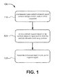
- FIG. 1 shows a flowchart of an example inspection process 100 for inspecting a component.
- FIG. 2 shows a schematic of an example inspection system 200 that can implement inspection process 100.
- the inspection system 200 uses ultrasonic signals to inspect an example component 300.
- the example component 300 is a composite I-Beam, e.g., one used in a rotorcraft.
- FIG. 3A shows a schematic diagram of a cross section of example component 300.
- the component 300 includes a cap 302, a flange 306, and a web 310.
- the cap 302, flange 306, and web 310 can be formed as one piece or be formed separately and attached together (e.g.
- a component like example component 300 can have component surfaces separate from or at angles to each other.
- the cap 302 includes an upper cap surface 304a and a lower cap surface 304b.
- the flange 306 includes an upper flange surface 308a and a lower flange surface 308b.
- the cap 302 and the flange 306 are connected by the web 310.
- the web 310 includes a left web surface 312a and a right web surface 312b.
- the array portions 204a-c can be positioned at one or more of these surfaces.
- FIG. 3B shows a schematic diagram of a component 350 having a J-beam shape.
- Component 350 includes a cap 352 with an upper cap surface 354a and a lower cap surface 354b.
- Component 350 also includes a web 360 with a left web surface 362a and right web surface 362b.
- Component 350 also includes a flange 356 with an upper flange surface 358a and a lower flange surface 358b.
- the array portions 204a-c can be positioned at these surfaces or on other surfaces of the component 350.
- Components 300 and 350 are examples; the inspection process 100 can inspect components having a shape other than an I-beam shape or a J-beam shape, such as a C-channel shape, a T-shape, a tubular shape, a flat shape, an irregular shape, or another shape.
- the component can be made of a composite material, a metallic material, a plastic material, or another material or combination of materials.
- the component can also be a composite pultrusion, an aluminum extrusion, made of roll-formed steel, or made of forged steel, or made by another manufacturing process.
- the inspection process 100 could be used to inspect components used in aircraft applications such as fixed-wing aircraft, tiltrotor aircraft, rotorcraft, or other aircraft.
- the inspection process 100 could also be used to inspect components used in other applications such as automotive systems (e.g. automobiles, ATVs, motorcycles, or other automotive systems), submersible systems, marine systems (e.g. personal watercraft, boats, or other marine systems), agricultural systems (e.g. tractors or other agricultural systems), power equipment (e.g. generators, lawn mowers, or other power equipment), construction equipment (e.g. industrial vehicles, heavy machinery, or other equipment), transportation vehicles (e.g., railcars, locomotives, or other vehicles), or other systems.
- automotive systems e.g. automobiles, ATVs, motorcycles, or other automotive systems
- submersible systems e.g. automobiles, ATVs, motorcycles, or other automotive systems
- marine systems e.g. personal watercraft, boats, or other marine systems
- agricultural systems e.g. tractors or other agricultural systems
- power equipment e.g. generators, lawn mowers, or other power equipment
- construction equipment e.g. industrial vehicles, heavy machinery, or other
- the inspection system 200 includes an ultrasonic probe array 204 including multiple transducer elements arranged in a row or rows.
- the transducer elements are devices that send ultrasonic energy into the component 300 and receive ultrasonic energy from the component 300.
- the transducer elements can be piezoelectric transducers or another type of transducer.
- the transducer elements receive ultrasonic energy transmitted through the component 200 as in a through-transmission technique.
- the transducer elements receive ultrasonic energy reflected from component surfaces or component defects as in a pulse-echo technique. In this manner, the transducer elements can be used to detect defects within the component 300.
- the transducer elements are in curved arrangements (e.g., concave, convex), in circular arrangements (e.g., an annular arrangement), in linear arrangements, in planar arrangements, or in arrangements of other shapes. Rigid or flexible transducer elements can be used.
- the ultrasonic probe array 204 is divided into multiple array portions, e.g., a first array portion 204a, a second array portion 204b, a third array portion 204c.
- the array portions 204a-c are shown in example inspection positions at surfaces on the component 300. Three array portions 204a-c are shown in FIG. 2 , though the array 204 can be divided into more or fewer array portions.
- the probe array 204 can be divided into multiple probe array portions.
- the ultrasonic probe array 204 of 64 transducer elements can be divided into three separate portions of 32 elements in the first array portion 204a, 18 elements in the second array portion 204b, and 14 elements in the third array portion 204c. This is one example; a probe array can be divided into more or fewer array portions with any suitable number of transducer elements apiece.
- the probe array 204 is configured as a phased array ultrasonic probe.
- An array portion can include a number of transducer elements such that the row of transducer elements spans a length substantially equal to or greater than a dimension of a surface of the component.
- the length of the row of first array portion 204a can approximately equal or exceed a width of the upper cap surface 304a of the component 300.
- a user can replace one array portion with another array portion of a different size.
- an array portion can be replaced by an array portion containing a larger number of transducer elements in order to inspect a wider component surface.
- the array portions 204a-c can be positioned at one or more of the surfaces on component 300.
- the first array portion 204a is positioned at the upper cap surface 304a to pass a first portion of the ultrasonic signal through the upper cap surface 304a
- the second array portion 204b is positioned at the upper flange surface 308a to pass a second portion of the ultrasonic signal through the upper flange surface 308a
- the third array portion 204c is positioned at the right web surface 312b to pass a third portion of the ultrasonic signal through the right web surface 312b.
- the array portions 204a-c can also be positioned on other component surfaces not shown or labeled.
- the ultrasonic probe array portions are attached to a retaining member (not shown) that includes at least one spring to retain the ultrasonic probe array portions against the respective component surfaces.
- the retaining member includes a mechanism such as an actuator, a scissoring mechanism, or another mechanism.
- the retaining member can maintain acoustic coupling between an array portion and a component surface.
- the retaining member can also maintain an array portion at a certain location as the array portion traverses the component. In this manner, a retaining member can improve inspection consistency and reduce operator fatigue.
- the user can reposition the array portions 204a-c to other surfaces or to different locations on the same surface.
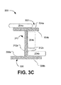
- FIG. 3C shows component 300 with array portions 204a-c positioned at different locations than shown in FIG. 3A .
- the user could reposition the first array portion 204a to a different location along the width of the upper cap surface 304a, as shown in FIG. 3C .
- the user could also, for example, reposition the third array portion 204c to the left web surface 312a or reposition the third array portion 204c to a different location on the right web surface 312b (as shown in FIG. 3C ).
- the second array portion 204b could be repositioned to the right side of the upper flange surface 308a, as shown in FIG. 3C .
- the third array portion 204c could be rotated 90° and shifted to reposition it at the lower cap surface 304b.
- one or more of the array portions 204a-c can be repositioned between inspection passes of the component 300.
- the ultrasonic probe array portions 204a-c can also be aligned or positioned on the respective component 300 surfaces such that the ultrasonic signal portions passed through the multiple ultrasonic probe array portions 204a-c do not interfere with each other.
- the first array portion 204a, the second array portion 204b, and the third array portion 204c are coupled to a signal generator 206.
- the signal generator 206 transmits an ultrasonic signal to the array portions 204a-c.
- the ultrasonic signal can be an analog signal, a digital signal, an amplified signal, an electronic signal, or other type of signal.
- the signal generator 206 can split a single ultrasonic signal into multiple ultrasonic signal portions and transmit the multiple ultrasonic signal portions to the array portions 204a-c.
- the array portions 204a-c pass the ultrasonic signal portions into the component surfaces.
- the signal generator 206 generates an electronic ultrasonic signal, and the array portions 204a-c pass portions of the ultrasonic signal into the component surfaces as an acoustic signal.
- the array portions 204a-c In response to the ultrasonic signals, the array portions 204a-c generate response signals.
- the response signals can be pulse-echo signals, through-transmission signals, or other types of ultrasonic signals.
- the multiple response signals are received, for example, by an ultrasonic signal receiver.
- the inspection system 200 includes an ultrasonic signal receiver 208 that is coupled to the array portions 204a-c and receives the response signals from the array portions 204a-c.
- the signal receiver 208 can aggregate the multiple signals from the array portions 204a-c into a single signal. As such, the signal receiver 208 receives a single response signal to the single ultrasonic signal generated by signal generator 206.
- the component is inspected based, in part, on the response signals.
- the component can be inspected using an inspection unit.
- the inspection system 200 includes an inspection unit 210 that is connected to the signal generator 206 and the signal receiver 206.
- the inspection unit 210 is used to inspect the component for defects based, in part, on the response signals from the array portions 204a-c.
- the inspection unit 210 can analyze the aggregated response signal from the signal receiver 208 to determine if the received response signals indicate a defect in the component.
- the inspection unit 210 is included as part of another system, such as a computer system or other data processing apparatus.
- the inspection unit 210 can include an encoder 212 that can detect the position of one or more of the array portions 204a-c on the surface of the component 300.
- the encoder 212 can detect the position of the array portions 204a-c as the array portions 204a-c are traversed along the surfaces of the component 300.
- the inspection system 200 records the response to the ultrasonic signal received through the ultrasonic probe array portions 204a-c.
- the data from the encoder 212 can be included with the recorded response. In this manner, data from the encoder 212 can be used to identify the location on the component 300 of defects or features detected by the inspection system 200. By identifying defect locations, further analysis of the defects could be performed. Recording the response signal can also allow the inspections of multiple components 300 to be compared. As such, manufacturing procedures, material compositions, etc. can be compared and improved based on the recorded signals.
- the inspection process 100 can be used to inspect parts for an aircraft. As an example, FIG. 4 shows a schematic diagram of an example rotorcraft 401.
- Rotorcraft 401 has a rotor system 403 with multiple rotor blades 405.
- Rotorcraft 401 can further include a fuselage 407, anti-torque system 409, and an empennage 411.
- the rotorcraft 401 can also include components 300 that can be inspected by inspection process 100.
- a component 300 is shown in an example location within the fuselage of the rotorcraft 401.
- FIG. 5 shows a schematic diagram of an example tiltrotor aircraft 501.
- Aircraft 501 includes a fuselage 507 with attached wings 505.
- Nacelles 503 are carried at the outboard ends of wings 505 and are rotatable between the helicopter-mode position shown and a forward-facing airplane-mode position (not shown).
- Nacelles 503 carry engines and transmissions for powering rotor systems 511 in rotation.
- An engine may be an internal combustion engine, an electrical power source and associated motor, or any other suitable technique for powering rotor system 511.
- the tiltrotor aircraft 501 can include components 200 that can be inspected by inspection process 100.
- a component 300 is shown in an example location within a wing of the tiltrotor aircraft 501.
Landscapes
- Physics & Mathematics (AREA)
- General Physics & Mathematics (AREA)
- Health & Medical Sciences (AREA)
- Life Sciences & Earth Sciences (AREA)
- Chemical & Material Sciences (AREA)
- Analytical Chemistry (AREA)
- Biochemistry (AREA)
- General Health & Medical Sciences (AREA)
- Immunology (AREA)
- Pathology (AREA)
- Acoustics & Sound (AREA)
- Investigating Or Analyzing Materials By The Use Of Ultrasonic Waves (AREA)
Abstract
Description
- This disclosure relates to the ultrasonic inspection of parts, e.g., composite components for an aircraft.
- In many industries, components are inspected for defects before installation. The components can be inspected using ultrasonic techniques. For example, composite components for use in an aircraft can be inspected for defects using an ultrasonic probe. Some components are large or have multiple surfaces that can increase the amount of time needed for a thorough ultrasonic inspection.
- This disclosure describes technologies relating to inspecting components with ultrasonic techniques.
- Certain aspects of the subject matter described here can be implemented as a method to inspect a composite component. The method includes traversing multiple ultrasonic probe array portions on respective multiple component surfaces of the composite component, wherein the multiple component surfaces are either separate from or at angles to each other. The method includes simultaneously passing an ultrasonic signal into the multiple component surfaces through the multiple ultrasonic probe array portions. The method also includes receiving a response to the ultrasonic signal through the multiple ultrasonic probe array portions.
- This, and other aspects, can include one or more of the following features. Simultaneously passing the ultrasonic signal into the multiple component surfaces through the multiple ultrasonic probe array portions can include dividing the ultrasonic signal into multiple ultrasonic signal portions and transmitting the ultrasonic signal portions to the multiple ultrasonic probe array portions. Receiving the response to the ultrasonic signal through the multiple ultrasonic probe array portions can include receiving multiple response signals to the respective multiple ultrasonic signal portions at the multiple component surfaces, each response signal received from a respective composite component surface in response to a respective ultrasonic signal portion. Receiving the response to the ultrasonic signal through the multiple ultrasonic probe array portions can also include aggregating the multiple response signals to form the response to the ultrasonic signal. Each ultrasonic probe array portion can include multiple ultrasonic probes. The multiple ultrasonic probes can be arranged in at least one row. A length of a row can be substantially equal to a dimension of a component surface on which the ultrasonic probe array portion is traversing. The method can include inspecting the composite component for at least one of porosity, voids, damage, delamination, or presence of foreign objects based, in part, on the received response. The composite component can be an I-beam including a cap including an upper cap surface and a lower cap surface, a flange including an upper flange surface and a lower flange surface, the flange being separate from the cap, and a web that connects the cap and the flange, the web including a left web surface and a right web surface, and wherein traversing multiple ultrasonic probe array portions on the respective multiple component surfaces includes simultaneously traversing a first ultrasonic probe array portion on the upper cap surface, a second ultrasonic probe array portion on the upper flange surface, and a third ultrasonic probe array portion on the right web surface. Traversing the multiple ultrasonic probe array portions on the respective multiple component surfaces can include aligning the multiple ultrasonic probe array portions on the respective multiple component surfaces such that ultrasonic signal portions passed through the multiple ultrasonic probe array portions do not interfere with each other. The method can include recording the response to the ultrasonic signal received through the multiple ultrasonic probe array portions and analyzing the recorded response signal to inspect the composite component. Traversing the multiple ultrasonic probe array portions on the respective multiple component surfaces includes attaching the multiple ultrasonic probe array portions to a retaining member that includes at least one spring to retain the multiple ultrasonic probe array portions against the respective multiple component surfaces.
- Certain aspects of the subject matter described here can be implemented as a method to inspect a composite component. The method includes simultaneously passing multiple ultrasonic signal portions through respective multiple component surfaces of the composite component, the multiple component surfaces being either separate from or at angles to each other. The method also includes receiving multiple response signals to the respective multiple ultrasonic signal portions from the multiple ultrasonic probe array portions and inspecting the composite component based, in part, on the multiple response signals.
- This, and other aspects, can include one or more of the following features. Passing an ultrasonic signal portion through each component surface can include positioning an ultrasonic probe array portion on each component surface and traversing the ultrasonic probe array portion on each component surface while passing an ultrasonic signal portion through each component surface. Each ultrasonic probe array portion can include multiple ultrasonic probes arranged in a row that spans a length of each component surface. The method can include dividing an ultrasonic signal into multiple ultrasonic signals and aggregating the multiple response signals into a response to the ultrasonic signal. The method can include recording the response and analyzing the response to inspect the composite component. Inspecting the composite component can include inspecting the composite component for at least one of porosity, voids, damage, delamination or presence of foreign objects based, in part, on the multiple response signals.
- Certain aspects of the subject matter described here can be implemented as a system for inspecting a composite component. The system includes an ultrasonic probe including multiple ultrasonic probe array portions to traverse respective multiple component surfaces of the composite component, wherein the multiple component surfaces are either separate from or at angles to each other. The system includes an ultrasonic signal generator to generate an ultrasonic signal to pass through the multiple ultrasonic probe array portions. The system also includes an ultrasonic signal receiver to receive multiple response signals to the ultrasonic signal from the multiple ultrasonic probe array portions. The system also includes an inspection unit to inspect the composite component based, in part, on the multiple response signals received by the ultrasonic signal receiver.
- This, and other aspects, can include one or more of the following features. The inspection unit can include an encoder to detect a position of an ultrasonic probe array portion on a component surface of the composite component. The composite component can be a rotorcraft I-beam.
- The details of one or more implementations of the subject matter described in this disclosure are set forth in the accompanying drawings and the description below. Other features, aspects, and advantages of the subject matter will become apparent from the description, the drawings, and the claims.
-
-
FIG. 1 shows a flowchart of an example inspection process for inspecting a component. -
FIG. 2 shows a schematic of an example inspection system that can implement the inspection process. -
FIGS. 3A-3C are schematic diagrams showing examples of components. -
FIG. 4 is a schematic diagram showing an example of a rotorcraft. -
FIG. 5 is a schematic diagram showing an example of a tiltrotor aircraft. - Like reference numbers and designations in the various drawings indicate like elements.
- This disclosure relates to the inspection of components using ultrasonic techniques. In some cases, components are inspected for defects, e.g., prior to installation, during periodic maintenance, in response to failure or at other times. For example, components made of a composite material can have defects that are not obvious or are internal to the component, such as voids or cracking. The component can be inspected using ultrasonic techniques that can detect internal or unobvious defects. For example, the component can be inspected using an ultrasonic probe or ultrasonic probe array. Some components can be large or have multiple surfaces, and each component surface may need inspection. For example, a composite stiffener or stringer used in an aircraft can have multiple surfaces at different angles to each other. Inspecting a component by inspecting each component surface sequentially using a single probe or probe array can take a long duration. Furthermore, using different probes to inspect the different component surfaces can be problematic if a different ultrasonic signal is provided to each of the different probes. For example, the use of multiple probes can require a separate ultrasonic signal generator and signal receiver for each probe.
- This disclosure describes a system for inspecting a component using an ultrasonic probe array. The inspection system can be used to inspect a component for defects such as porosity, voids, damage, cracks, corrosion, delamination, the presence of foreign objects, or other defects. The inspection system uses multiple portions of an ultrasonic probe array to inspect a component. A signal generator splits a single ultrasonic signal into multiple signal portions, and transmits each signal portion to a respective portion of the probe array. Each array portion is positioned at a separate surface of the component. Thus, multiple surfaces of the component are inspected simultaneously. The array portions can be traversed on each component surface while passing a respective ultrasonic signal portion through each component surface. In some cases, the inspection system is traversed along the component, and in some cases, the component is passed through the inspection system. When responses to the multiple signal portions are received, they are aggregated into a single response signal to the single ultrasonic signal. By inspecting multiple surfaces simultaneously, the process of inspecting the component is made more efficient, and the time to inspect a large part can be significantly reduced. The inspection system can also reduce fatigue or risk of injury for an operator, as fewer inspection passes may be needed. Furthermore, the inspection data can be recorded and saved for further analysis. Analyzing recorded inspection data can reduce the risk of escapes and improve the probability of detection.
-
FIG. 1 shows a flowchart of anexample inspection process 100 for inspecting a component. At 110, multiple ultrasonic signal portions are simultaneously passed through multiple surfaces of the component.FIG. 2 shows a schematic of anexample inspection system 200 that can implementinspection process 100. Theinspection system 200 uses ultrasonic signals to inspect anexample component 300. InFIG. 2 , theexample component 300 is a composite I-Beam, e.g., one used in a rotorcraft.FIG. 3A shows a schematic diagram of a cross section ofexample component 300. Thecomponent 300 includes acap 302, aflange 306, and aweb 310. Thecap 302,flange 306, andweb 310 can be formed as one piece or be formed separately and attached together (e.g. by bonding, adhesion, or another technique). A component likeexample component 300 can have component surfaces separate from or at angles to each other. For example thecap 302 includes anupper cap surface 304a and alower cap surface 304b. Theflange 306 includes anupper flange surface 308a and alower flange surface 308b. Thecap 302 and theflange 306 are connected by theweb 310. Theweb 310 includes aleft web surface 312a and aright web surface 312b. Thearray portions 204a-c can be positioned at one or more of these surfaces. - As another example component,
FIG. 3B shows a schematic diagram of acomponent 350 having a J-beam shape.Component 350 includes acap 352 with anupper cap surface 354a and alower cap surface 354b.Component 350 also includes aweb 360 with aleft web surface 362a andright web surface 362b.Component 350 also includes aflange 356 with anupper flange surface 358a and alower flange surface 358b. Thearray portions 204a-c can be positioned at these surfaces or on other surfaces of thecomponent 350. -
Components inspection process 100 can inspect components having a shape other than an I-beam shape or a J-beam shape, such as a C-channel shape, a T-shape, a tubular shape, a flat shape, an irregular shape, or another shape. Furthermore, the component can be made of a composite material, a metallic material, a plastic material, or another material or combination of materials. The component can also be a composite pultrusion, an aluminum extrusion, made of roll-formed steel, or made of forged steel, or made by another manufacturing process. Theinspection process 100 could be used to inspect components used in aircraft applications such as fixed-wing aircraft, tiltrotor aircraft, rotorcraft, or other aircraft. Theinspection process 100 could also be used to inspect components used in other applications such as automotive systems (e.g. automobiles, ATVs, motorcycles, or other automotive systems), submersible systems, marine systems (e.g. personal watercraft, boats, or other marine systems), agricultural systems (e.g. tractors or other agricultural systems), power equipment (e.g. generators, lawn mowers, or other power equipment), construction equipment (e.g. industrial vehicles, heavy machinery, or other equipment), transportation vehicles (e.g., railcars, locomotives, or other vehicles), or other systems. - The
inspection system 200 includes an ultrasonic probe array 204 including multiple transducer elements arranged in a row or rows. The transducer elements are devices that send ultrasonic energy into thecomponent 300 and receive ultrasonic energy from thecomponent 300. For example, the transducer elements can be piezoelectric transducers or another type of transducer. In some cases, the transducer elements receive ultrasonic energy transmitted through thecomponent 200 as in a through-transmission technique. In other cases, the transducer elements receive ultrasonic energy reflected from component surfaces or component defects as in a pulse-echo technique. In this manner, the transducer elements can be used to detect defects within thecomponent 300. In some implementations, the transducer elements are in curved arrangements (e.g., concave, convex), in circular arrangements (e.g., an annular arrangement), in linear arrangements, in planar arrangements, or in arrangements of other shapes. Rigid or flexible transducer elements can be used. - The ultrasonic probe array 204 is divided into multiple array portions, e.g., a
first array portion 204a, asecond array portion 204b, athird array portion 204c. Thearray portions 204a-c are shown in example inspection positions at surfaces on thecomponent 300. Threearray portions 204a-c are shown inFIG. 2 , though the array 204 can be divided into more or fewer array portions. The probe array 204 can be divided into multiple probe array portions. For example, the ultrasonic probe array 204 of 64 transducer elements can be divided into three separate portions of 32 elements in thefirst array portion 204a, 18 elements in thesecond array portion 204b, and 14 elements in thethird array portion 204c. This is one example; a probe array can be divided into more or fewer array portions with any suitable number of transducer elements apiece. In some implementations, the probe array 204 is configured as a phased array ultrasonic probe. - An array portion can include a number of transducer elements such that the row of transducer elements spans a length substantially equal to or greater than a dimension of a surface of the component. For example, the length of the row of
first array portion 204a can approximately equal or exceed a width of theupper cap surface 304a of thecomponent 300. In some implementations, a user can replace one array portion with another array portion of a different size. For example, an array portion can be replaced by an array portion containing a larger number of transducer elements in order to inspect a wider component surface. - The
array portions 204a-c can be positioned at one or more of the surfaces oncomponent 300. For example, referring toFIG. 3 , thefirst array portion 204a is positioned at theupper cap surface 304a to pass a first portion of the ultrasonic signal through theupper cap surface 304a, thesecond array portion 204b is positioned at theupper flange surface 308a to pass a second portion of the ultrasonic signal through theupper flange surface 308a, and thethird array portion 204c is positioned at theright web surface 312b to pass a third portion of the ultrasonic signal through theright web surface 312b. Thearray portions 204a-c can also be positioned on other component surfaces not shown or labeled. - In some implementations, the ultrasonic probe array portions are attached to a retaining member (not shown) that includes at least one spring to retain the ultrasonic probe array portions against the respective component surfaces. In some implementations, the retaining member includes a mechanism such as an actuator, a scissoring mechanism, or another mechanism. The retaining member can maintain acoustic coupling between an array portion and a component surface. The retaining member can also maintain an array portion at a certain location as the array portion traverses the component. In this manner, a retaining member can improve inspection consistency and reduce operator fatigue.
- In some cases, the user can reposition the
array portions 204a-c to other surfaces or to different locations on the same surface. As an example,FIG. 3C showscomponent 300 witharray portions 204a-c positioned at different locations than shown inFIG. 3A . After an inspection, the user could reposition thefirst array portion 204a to a different location along the width of theupper cap surface 304a, as shown inFIG. 3C . The user could also, for example, reposition thethird array portion 204c to theleft web surface 312a or reposition thethird array portion 204c to a different location on theright web surface 312b (as shown inFIG. 3C ). Additionally, thesecond array portion 204b could be repositioned to the right side of theupper flange surface 308a, as shown inFIG. 3C . As another example, thethird array portion 204c could be rotated 90° and shifted to reposition it at thelower cap surface 304b. In some implementations, one or more of thearray portions 204a-c can be repositioned between inspection passes of thecomponent 300. The ultrasonicprobe array portions 204a-c can also be aligned or positioned on therespective component 300 surfaces such that the ultrasonic signal portions passed through the multiple ultrasonicprobe array portions 204a-c do not interfere with each other. - The
first array portion 204a, thesecond array portion 204b, and thethird array portion 204c are coupled to asignal generator 206. Thesignal generator 206 transmits an ultrasonic signal to thearray portions 204a-c. For example, the ultrasonic signal can be an analog signal, a digital signal, an amplified signal, an electronic signal, or other type of signal. Thesignal generator 206 can split a single ultrasonic signal into multiple ultrasonic signal portions and transmit the multiple ultrasonic signal portions to thearray portions 204a-c. Thearray portions 204a-c pass the ultrasonic signal portions into the component surfaces. In some implementations, thesignal generator 206 generates an electronic ultrasonic signal, and thearray portions 204a-c pass portions of the ultrasonic signal into the component surfaces as an acoustic signal. - In response to the ultrasonic signals, the
array portions 204a-c generate response signals. The response signals can be pulse-echo signals, through-transmission signals, or other types of ultrasonic signals. At 120, the multiple response signals are received, for example, by an ultrasonic signal receiver. Theinspection system 200 includes anultrasonic signal receiver 208 that is coupled to thearray portions 204a-c and receives the response signals from thearray portions 204a-c. Thesignal receiver 208 can aggregate the multiple signals from thearray portions 204a-c into a single signal. As such, thesignal receiver 208 receives a single response signal to the single ultrasonic signal generated bysignal generator 206. - At 130, the component is inspected based, in part, on the response signals. For example, the component can be inspected using an inspection unit. The
inspection system 200 includes aninspection unit 210 that is connected to thesignal generator 206 and thesignal receiver 206. Theinspection unit 210 is used to inspect the component for defects based, in part, on the response signals from thearray portions 204a-c. For example, theinspection unit 210 can analyze the aggregated response signal from thesignal receiver 208 to determine if the received response signals indicate a defect in the component. In some implementations, theinspection unit 210 is included as part of another system, such as a computer system or other data processing apparatus. - The
inspection unit 210 can include anencoder 212 that can detect the position of one or more of thearray portions 204a-c on the surface of thecomponent 300. For example, theencoder 212 can detect the position of thearray portions 204a-c as thearray portions 204a-c are traversed along the surfaces of thecomponent 300. - In some implementations, the
inspection system 200 records the response to the ultrasonic signal received through the ultrasonicprobe array portions 204a-c. In some implementations, the data from theencoder 212 can be included with the recorded response. In this manner, data from theencoder 212 can be used to identify the location on thecomponent 300 of defects or features detected by theinspection system 200. By identifying defect locations, further analysis of the defects could be performed. Recording the response signal can also allow the inspections ofmultiple components 300 to be compared. As such, manufacturing procedures, material compositions, etc. can be compared and improved based on the recorded signals. Theinspection process 100 can be used to inspect parts for an aircraft. As an example,FIG. 4 shows a schematic diagram of anexample rotorcraft 401.Rotorcraft 401 has arotor system 403 withmultiple rotor blades 405.Rotorcraft 401 can further include afuselage 407,anti-torque system 409, and anempennage 411. Therotorcraft 401 can also includecomponents 300 that can be inspected byinspection process 100. Acomponent 300 is shown in an example location within the fuselage of therotorcraft 401. - As another example aircraft,
FIG. 5 shows a schematic diagram of anexample tiltrotor aircraft 501.Aircraft 501 includes afuselage 507 with attachedwings 505.Nacelles 503 are carried at the outboard ends ofwings 505 and are rotatable between the helicopter-mode position shown and a forward-facing airplane-mode position (not shown).Nacelles 503 carry engines and transmissions for poweringrotor systems 511 in rotation. An engine may be an internal combustion engine, an electrical power source and associated motor, or any other suitable technique for poweringrotor system 511. Thetiltrotor aircraft 501 can includecomponents 200 that can be inspected byinspection process 100. Acomponent 300 is shown in an example location within a wing of thetiltrotor aircraft 501. - Thus, particular implementations of the subject matter have been described. Other implementations are within the scope of the following claims. In some cases, the actions recited in the claims can be performed in a different order and still achieve desirable results. In addition, the processes depicted in the accompanying figures do not necessarily require the particular order shown, or sequential order, to achieve desirable results.
Claims (15)
- A method to inspect a composite component, the method comprising:traversing a plurality of ultrasonic probe array portions on a respective plurality of component surfaces of the composite component, wherein the plurality of component surfaces are either separate from or at angles to each other;simultaneously passing an ultrasonic signal into the plurality of component surfaces through the plurality of ultrasonic probe array portions;and receiving a response to the ultrasonic signal through the plurality of ultrasonic probe array portions.
- The method of claim 1, wherein simultaneously passing the ultrasonic signal into the plurality of component surfaces through the plurality of ultrasonic probe array portions comprises:dividing the ultrasonic signal into a plurality of ultrasonic signal portions; andtransmitting the ultrasonic signal portions to the plurality of ultrasonic probe array portions.
- The method of claim 2, receiving the response to the ultrasonic signal through the plurality of ultrasonic probe array portions comprises:receiving a plurality of response signals to the respective plurality of ultrasonic signal portions at the plurality of component surfaces, each response signal received from a respective composite component surface in response to a respective ultrasonic signal portion; andaggregating the plurality of response signals to form the response to the ultrasonic signal.
- The method of claim 1, wherein each ultrasonic probe array portion includes a plurality of ultrasonic probes and optionally,
wherein the plurality of ultrasonic probes are arranged in at least one row,
and optionally,
wherein a length of a row is substantially equal to a dimension of a component surface on which the ultrasonic probe array portion is traversing. - The method of claim 1, further comprising inspecting the composite component for at least one of porosity, voids, damage, delamination, or presence of foreign objects based, in part, on the received response.
- The method of claim 1, wherein the composite component is an I-beam comprising a cap including an upper cap surface and a lower cap surface, a flange including an upper flange surface and a lower flange surface, the flange being separate from the cap, and a web that connects the cap and the flange, the web including a left web surface and a right web surface, and wherein traversing a plurality of ultrasonic probe array portions on the respective plurality of component surfaces comprises simultaneously traversing a first ultrasonic probe array portion on the upper cap surface, a second ultrasonic probe array portion on the upper flange surface, and a third ultrasonic probe array portion on the right web surface.
- The method of claim 1, wherein traversing the plurality of ultrasonic probe array portions on the respective plurality of component surfaces comprises aligning the plurality of ultrasonic probe array portions on the respective plurality of component surfaces such that ultrasonic signal portions passed through the plurality of ultrasonic probe array portions do not interfere with each other.
- The method of claim 1, further comprising:recording the response to the ultrasonic signal received through the plurality of ultrasonic probe array portions; andanalyzing the recorded response signal to inspect the composite component.
- The method of claim 1, wherein traversing the plurality of ultrasonic probe array portions on the respective plurality of component surfaces comprises attaching the plurality of ultrasonic probe array portions to a retaining member that includes at least one spring to retain the plurality of ultrasonic probe array portions against the respective plurality of component surfaces.
- A method to inspect a composite component, the method comprising:simultaneously passing a plurality of ultrasonic signal portions through a respective plurality of component surfaces of the composite component, the plurality of component surfaces being either separate from or at angles to each other;receiving a plurality of response signals to the respective plurality of ultrasonic signal portions from the plurality of ultrasonic probe array portions; andinspecting the composite component based, in part, on the plurality of response signals.
- The method of claim 10, wherein passing an ultrasonic signal portion through each component surface comprises:positioning an ultrasonic probe array portion on each component surface; andtraversing the ultrasonic probe array portion on each component surface while passing an ultrasonic signal portion through each component surface, and optionally,wherein each ultrasonic probe array portion comprises a plurality of ultrasonic probes arranged in a row that spans a length of each component surface.
- The method of claim 10, further comprising:dividing an ultrasonic signal into the plurality of ultrasonic signals; andaggregating the plurality of response signals into a response to the ultrasonic signal, and optionally,further comprising:recording the response; andanalyzing the response to inspect the composite component.
- The method of claim 10, wherein inspecting the composite component comprises inspecting the composite component for at least one of porosity, voids, damage, delamination or presence of foreign objects based, in part, on the plurality of response signals.
- A system for inspecting a composite component, the system comprising:an ultrasonic probe comprising a plurality of ultrasonic probe array portions to traverse a respective plurality of component surfaces of the composite component, wherein the plurality of component surfaces are either separate from or at angles to each other;an ultrasonic signal generator to generate an ultrasonic signal to pass through the plurality of ultrasonic probe array portions;an ultrasonic signal receiver to receive a plurality of response signals to the ultrasonic signal from the plurality of ultrasonic probe array portions; andan inspection unit to inspect the composite component based, in part, on the plurality of response signals received by the ultrasonic signal receiver.
- The system of claim 14, wherein the inspection unit comprises an encoder to detect a position of an ultrasonic probe array portion on a component surface of the composite component or wherein the composite component is a rotorcraft I-beam.
Applications Claiming Priority (1)
| Application Number | Priority Date | Filing Date | Title |
|---|---|---|---|
| US14/476,091 US9891196B2 (en) | 2014-09-03 | 2014-09-03 | Ultrasonic inspection of composite parts |
Publications (2)
| Publication Number | Publication Date |
|---|---|
| EP2993470A1 true EP2993470A1 (en) | 2016-03-09 |
| EP2993470B1 EP2993470B1 (en) | 2018-07-11 |
Family
ID=51703104
Family Applications (1)
| Application Number | Title | Priority Date | Filing Date |
|---|---|---|---|
| EP14189245.5A Active EP2993470B1 (en) | 2014-09-03 | 2014-10-16 | Ultrasonic inspection of composite parts |
Country Status (3)
| Country | Link |
|---|---|
| US (1) | US9891196B2 (en) |
| EP (1) | EP2993470B1 (en) |
| CA (1) | CA2901854C (en) |
Families Citing this family (5)
| Publication number | Priority date | Publication date | Assignee | Title |
|---|---|---|---|---|
| US9939391B1 (en) | 2016-12-15 | 2018-04-10 | Bell Helicopter Textron Inc. | Inspection method using a film overlay |
| US10352906B2 (en) | 2016-12-15 | 2019-07-16 | Bell Helicopter Textron Inc. | Through-transmission ultrasonic testing apparatus |
| CN113063853B (en) * | 2021-03-26 | 2024-03-15 | 睿信汽车电器(荆州)有限公司 | An acoustic flaw detection system and detection method for the inner hole of a generator rotor |
| US12553862B2 (en) * | 2023-07-07 | 2026-02-17 | The Boeing Company | Method and apparatus for analyzing a composite structure |
| TWI893813B (en) * | 2024-05-20 | 2025-08-11 | 中國鋼鐵股份有限公司 | H-beam testing device |
Citations (6)
| Publication number | Priority date | Publication date | Assignee | Title |
|---|---|---|---|---|
| US4848159A (en) * | 1987-05-22 | 1989-07-18 | The Boeing Company | Ultrasonic inspection probe for laminated structures |
| US6167760B1 (en) * | 1993-07-01 | 2001-01-02 | The Boeing Company | Ultrasonic inspection system for laminated stiffeners |
| US20060162456A1 (en) * | 2005-01-24 | 2006-07-27 | Kennedy James C | Non-destructive stringer inspection apparatus and method |
| US20070044563A1 (en) * | 2005-08-26 | 2007-03-01 | The Boeing Company | Rapid prototype integrated linear ultrasonic transducer inspection apparatus, systems, and methods |
| US20130233082A1 (en) * | 2010-10-29 | 2013-09-12 | Airbus Operations Limited | Ultrasonic inspection tool |
| FR2997190A1 (en) * | 2012-10-19 | 2014-04-25 | Eads Europ Aeronautic Defence | ULTRASONIC CONTACT MEASURING PROBE OF AN OBJECT AND METHOD OF MANUFACTURING THE SAME |
Family Cites Families (5)
| Publication number | Priority date | Publication date | Assignee | Title |
|---|---|---|---|---|
| EP0709673A1 (en) * | 1994-10-25 | 1996-05-01 | Laboratoires D'electronique Philips | Apparatus for non-destructive testing of hollow tubular articles with ultrasound |
| US7430913B2 (en) * | 2005-08-26 | 2008-10-07 | The Boeing Company | Rapid prototype integrated matrix ultrasonic transducer array inspection apparatus, systems, and methods |
| US8225667B2 (en) * | 2008-04-28 | 2012-07-24 | Veracity Technology Solutions, Llc | Continuous autonomous tester |
| US7848894B2 (en) * | 2009-03-09 | 2010-12-07 | The Boeing Company | Non-destructive inspection apparatus |
| US9395339B2 (en) * | 2013-08-26 | 2016-07-19 | The Boeing Comapany | Apparatus for non-destructive inspection of stringers |
-
2014
- 2014-09-03 US US14/476,091 patent/US9891196B2/en active Active
- 2014-10-16 EP EP14189245.5A patent/EP2993470B1/en active Active
-
2015
- 2015-08-26 CA CA2901854A patent/CA2901854C/en active Active
Patent Citations (6)
| Publication number | Priority date | Publication date | Assignee | Title |
|---|---|---|---|---|
| US4848159A (en) * | 1987-05-22 | 1989-07-18 | The Boeing Company | Ultrasonic inspection probe for laminated structures |
| US6167760B1 (en) * | 1993-07-01 | 2001-01-02 | The Boeing Company | Ultrasonic inspection system for laminated stiffeners |
| US20060162456A1 (en) * | 2005-01-24 | 2006-07-27 | Kennedy James C | Non-destructive stringer inspection apparatus and method |
| US20070044563A1 (en) * | 2005-08-26 | 2007-03-01 | The Boeing Company | Rapid prototype integrated linear ultrasonic transducer inspection apparatus, systems, and methods |
| US20130233082A1 (en) * | 2010-10-29 | 2013-09-12 | Airbus Operations Limited | Ultrasonic inspection tool |
| FR2997190A1 (en) * | 2012-10-19 | 2014-04-25 | Eads Europ Aeronautic Defence | ULTRASONIC CONTACT MEASURING PROBE OF AN OBJECT AND METHOD OF MANUFACTURING THE SAME |
Also Published As
| Publication number | Publication date |
|---|---|
| CA2901854C (en) | 2021-05-11 |
| US9891196B2 (en) | 2018-02-13 |
| US20160061779A1 (en) | 2016-03-03 |
| CA2901854A1 (en) | 2016-03-03 |
| EP2993470B1 (en) | 2018-07-11 |
Similar Documents
| Publication | Publication Date | Title |
|---|---|---|
| CA2901854C (en) | Ultrasonic inspection of composite parts | |
| US7712369B2 (en) | Array-based system and method for inspecting a workpiece with backscattered ultrasonic signals | |
| US7367236B2 (en) | Non-destructive inspection system and associated method | |
| US7757558B2 (en) | Method and apparatus for inspecting a workpiece with angularly offset ultrasonic signals | |
| US7698949B2 (en) | Active washers for monitoring bolted joints | |
| EP2345881B1 (en) | Crawling automated scanner for non-destructive inspection of aerospace structural elements | |
| US10429351B2 (en) | Health monitoring of composite structures | |
| US7617730B2 (en) | Ultrasonic inspection and repair mode selection | |
| CN106796204A (en) | System for checking track with phased-array ultrasonic | |
| KR102168442B1 (en) | Apparatus for non-destructive inspection of stringers | |
| US8015877B2 (en) | Imaging an anomaly using backscattered waves | |
| US9964521B2 (en) | Detecting damage in a composite panel without removing overlying insulation | |
| JP2013501238A (en) | System and method for detecting anomalies in a hidden layer of a multilayer structure | |
| EP2827142B1 (en) | Ultrasonic inspection system for non-planar surfaces | |
| EP2984479B1 (en) | Ultrasonic inspection using incidence angles | |
| EP3001189B1 (en) | Implementing steep delta wave technique to inspect joints | |
| US9239315B1 (en) | Patch and methods for monitoring a structure including a patch | |
| Mandal et al. | A comprehensive review on recent technological advancements in ship hull health monitoring systems | |
| Hillger et al. | Advanced NDT techniques for damage detection in a honeycomb composite helicopter tailboom | |
| Bellan et al. | REVIEW OF NON DESTRUCTIVE TESTING TECHNIQUES FOR COMPOSITES MATERIALS AND NEW APPLICATIONS OF PIEZO-POLYMER INTERDIGITAL TRANSDUCERS | |
| JPH04201696A (en) | aircraft diagnostic system | |
| Szewieczek et al. | Ultrasonic impact detection techniques for an EC135 tailboom |
Legal Events
| Date | Code | Title | Description |
|---|---|---|---|
| PUAI | Public reference made under article 153(3) epc to a published international application that has entered the european phase |
Free format text: ORIGINAL CODE: 0009012 |
|
| 17P | Request for examination filed |
Effective date: 20141016 |
|
| AK | Designated contracting states |
Kind code of ref document: A1 Designated state(s): AL AT BE BG CH CY CZ DE DK EE ES FI FR GB GR HR HU IE IS IT LI LT LU LV MC MK MT NL NO PL PT RO RS SE SI SK SM TR |
|
| AX | Request for extension of the european patent |
Extension state: BA ME |
|
| RIC1 | Information provided on ipc code assigned before grant |
Ipc: G01N 29/34 20060101ALI20180305BHEP Ipc: G01N 29/22 20060101AFI20180305BHEP |
|
| GRAP | Despatch of communication of intention to grant a patent |
Free format text: ORIGINAL CODE: EPIDOSNIGR1 |
|
| INTG | Intention to grant announced |
Effective date: 20180420 |
|
| GRAS | Grant fee paid |
Free format text: ORIGINAL CODE: EPIDOSNIGR3 |
|
| GRAA | (expected) grant |
Free format text: ORIGINAL CODE: 0009210 |
|
| AK | Designated contracting states |
Kind code of ref document: B1 Designated state(s): AL AT BE BG CH CY CZ DE DK EE ES FI FR GB GR HR HU IE IS IT LI LT LU LV MC MK MT NL NO PL PT RO RS SE SI SK SM TR |
|
| REG | Reference to a national code |
Ref country code: GB Ref legal event code: FG4D |
|
| REG | Reference to a national code |
Ref country code: CH Ref legal event code: EP |
|
| REG | Reference to a national code |
Ref country code: AT Ref legal event code: REF Ref document number: 1017419 Country of ref document: AT Kind code of ref document: T Effective date: 20180715 |
|
| REG | Reference to a national code |
Ref country code: IE Ref legal event code: FG4D |
|
| REG | Reference to a national code |
Ref country code: DE Ref legal event code: R096 Ref document number: 602014028196 Country of ref document: DE |
|
| REG | Reference to a national code |
Ref country code: FR Ref legal event code: PLFP Year of fee payment: 5 |
|
| REG | Reference to a national code |
Ref country code: NL Ref legal event code: MP Effective date: 20180711 |
|
| REG | Reference to a national code |
Ref country code: LT Ref legal event code: MG4D |
|
| REG | Reference to a national code |
Ref country code: AT Ref legal event code: MK05 Ref document number: 1017419 Country of ref document: AT Kind code of ref document: T Effective date: 20180711 |
|
| PG25 | Lapsed in a contracting state [announced via postgrant information from national office to epo] |
Ref country code: NL Free format text: LAPSE BECAUSE OF FAILURE TO SUBMIT A TRANSLATION OF THE DESCRIPTION OR TO PAY THE FEE WITHIN THE PRESCRIBED TIME-LIMIT Effective date: 20180711 |
|
| PG25 | Lapsed in a contracting state [announced via postgrant information from national office to epo] |
Ref country code: RS Free format text: LAPSE BECAUSE OF FAILURE TO SUBMIT A TRANSLATION OF THE DESCRIPTION OR TO PAY THE FEE WITHIN THE PRESCRIBED TIME-LIMIT Effective date: 20180711 Ref country code: IS Free format text: LAPSE BECAUSE OF FAILURE TO SUBMIT A TRANSLATION OF THE DESCRIPTION OR TO PAY THE FEE WITHIN THE PRESCRIBED TIME-LIMIT Effective date: 20181111 Ref country code: PL Free format text: LAPSE BECAUSE OF FAILURE TO SUBMIT A TRANSLATION OF THE DESCRIPTION OR TO PAY THE FEE WITHIN THE PRESCRIBED TIME-LIMIT Effective date: 20180711 Ref country code: SE Free format text: LAPSE BECAUSE OF FAILURE TO SUBMIT A TRANSLATION OF THE DESCRIPTION OR TO PAY THE FEE WITHIN THE PRESCRIBED TIME-LIMIT Effective date: 20180711 Ref country code: AT Free format text: LAPSE BECAUSE OF FAILURE TO SUBMIT A TRANSLATION OF THE DESCRIPTION OR TO PAY THE FEE WITHIN THE PRESCRIBED TIME-LIMIT Effective date: 20180711 Ref country code: BG Free format text: LAPSE BECAUSE OF FAILURE TO SUBMIT A TRANSLATION OF THE DESCRIPTION OR TO PAY THE FEE WITHIN THE PRESCRIBED TIME-LIMIT Effective date: 20181011 Ref country code: LT Free format text: LAPSE BECAUSE OF FAILURE TO SUBMIT A TRANSLATION OF THE DESCRIPTION OR TO PAY THE FEE WITHIN THE PRESCRIBED TIME-LIMIT Effective date: 20180711 Ref country code: NO Free format text: LAPSE BECAUSE OF FAILURE TO SUBMIT A TRANSLATION OF THE DESCRIPTION OR TO PAY THE FEE WITHIN THE PRESCRIBED TIME-LIMIT Effective date: 20181011 Ref country code: GR Free format text: LAPSE BECAUSE OF FAILURE TO SUBMIT A TRANSLATION OF THE DESCRIPTION OR TO PAY THE FEE WITHIN THE PRESCRIBED TIME-LIMIT Effective date: 20181012 Ref country code: FI Free format text: LAPSE BECAUSE OF FAILURE TO SUBMIT A TRANSLATION OF THE DESCRIPTION OR TO PAY THE FEE WITHIN THE PRESCRIBED TIME-LIMIT Effective date: 20180711 |
|
| PG25 | Lapsed in a contracting state [announced via postgrant information from national office to epo] |
Ref country code: HR Free format text: LAPSE BECAUSE OF FAILURE TO SUBMIT A TRANSLATION OF THE DESCRIPTION OR TO PAY THE FEE WITHIN THE PRESCRIBED TIME-LIMIT Effective date: 20180711 Ref country code: ES Free format text: LAPSE BECAUSE OF FAILURE TO SUBMIT A TRANSLATION OF THE DESCRIPTION OR TO PAY THE FEE WITHIN THE PRESCRIBED TIME-LIMIT Effective date: 20180711 Ref country code: AL Free format text: LAPSE BECAUSE OF FAILURE TO SUBMIT A TRANSLATION OF THE DESCRIPTION OR TO PAY THE FEE WITHIN THE PRESCRIBED TIME-LIMIT Effective date: 20180711 Ref country code: LV Free format text: LAPSE BECAUSE OF FAILURE TO SUBMIT A TRANSLATION OF THE DESCRIPTION OR TO PAY THE FEE WITHIN THE PRESCRIBED TIME-LIMIT Effective date: 20180711 |
|
| REG | Reference to a national code |
Ref country code: DE Ref legal event code: R097 Ref document number: 602014028196 Country of ref document: DE |
|
| PG25 | Lapsed in a contracting state [announced via postgrant information from national office to epo] |
Ref country code: RO Free format text: LAPSE BECAUSE OF FAILURE TO SUBMIT A TRANSLATION OF THE DESCRIPTION OR TO PAY THE FEE WITHIN THE PRESCRIBED TIME-LIMIT Effective date: 20180711 Ref country code: CZ Free format text: LAPSE BECAUSE OF FAILURE TO SUBMIT A TRANSLATION OF THE DESCRIPTION OR TO PAY THE FEE WITHIN THE PRESCRIBED TIME-LIMIT Effective date: 20180711 Ref country code: EE Free format text: LAPSE BECAUSE OF FAILURE TO SUBMIT A TRANSLATION OF THE DESCRIPTION OR TO PAY THE FEE WITHIN THE PRESCRIBED TIME-LIMIT Effective date: 20180711 |
|
| PLBE | No opposition filed within time limit |
Free format text: ORIGINAL CODE: 0009261 |
|
| STAA | Information on the status of an ep patent application or granted ep patent |
Free format text: STATUS: NO OPPOSITION FILED WITHIN TIME LIMIT |
|
| PG25 | Lapsed in a contracting state [announced via postgrant information from national office to epo] |
Ref country code: SM Free format text: LAPSE BECAUSE OF FAILURE TO SUBMIT A TRANSLATION OF THE DESCRIPTION OR TO PAY THE FEE WITHIN THE PRESCRIBED TIME-LIMIT Effective date: 20180711 Ref country code: SK Free format text: LAPSE BECAUSE OF FAILURE TO SUBMIT A TRANSLATION OF THE DESCRIPTION OR TO PAY THE FEE WITHIN THE PRESCRIBED TIME-LIMIT Effective date: 20180711 Ref country code: DK Free format text: LAPSE BECAUSE OF FAILURE TO SUBMIT A TRANSLATION OF THE DESCRIPTION OR TO PAY THE FEE WITHIN THE PRESCRIBED TIME-LIMIT Effective date: 20180711 |
|
| REG | Reference to a national code |
Ref country code: CH Ref legal event code: PL |
|
| 26N | No opposition filed |
Effective date: 20190412 |
|
| REG | Reference to a national code |
Ref country code: BE Ref legal event code: MM Effective date: 20181031 |
|
| PG25 | Lapsed in a contracting state [announced via postgrant information from national office to epo] |
Ref country code: LU Free format text: LAPSE BECAUSE OF NON-PAYMENT OF DUE FEES Effective date: 20181016 Ref country code: MC Free format text: LAPSE BECAUSE OF FAILURE TO SUBMIT A TRANSLATION OF THE DESCRIPTION OR TO PAY THE FEE WITHIN THE PRESCRIBED TIME-LIMIT Effective date: 20180711 |
|
| REG | Reference to a national code |
Ref country code: IE Ref legal event code: MM4A |
|
| PG25 | Lapsed in a contracting state [announced via postgrant information from national office to epo] |
Ref country code: BE Free format text: LAPSE BECAUSE OF NON-PAYMENT OF DUE FEES Effective date: 20181031 Ref country code: SI Free format text: LAPSE BECAUSE OF FAILURE TO SUBMIT A TRANSLATION OF THE DESCRIPTION OR TO PAY THE FEE WITHIN THE PRESCRIBED TIME-LIMIT Effective date: 20180711 Ref country code: LI Free format text: LAPSE BECAUSE OF NON-PAYMENT OF DUE FEES Effective date: 20181031 Ref country code: CH Free format text: LAPSE BECAUSE OF NON-PAYMENT OF DUE FEES Effective date: 20181031 |
|
| PG25 | Lapsed in a contracting state [announced via postgrant information from national office to epo] |
Ref country code: IE Free format text: LAPSE BECAUSE OF NON-PAYMENT OF DUE FEES Effective date: 20181016 |
|
| PG25 | Lapsed in a contracting state [announced via postgrant information from national office to epo] |
Ref country code: MT Free format text: LAPSE BECAUSE OF NON-PAYMENT OF DUE FEES Effective date: 20181016 |
|
| PG25 | Lapsed in a contracting state [announced via postgrant information from national office to epo] |
Ref country code: TR Free format text: LAPSE BECAUSE OF FAILURE TO SUBMIT A TRANSLATION OF THE DESCRIPTION OR TO PAY THE FEE WITHIN THE PRESCRIBED TIME-LIMIT Effective date: 20180711 |
|
| PG25 | Lapsed in a contracting state [announced via postgrant information from national office to epo] |
Ref country code: PT Free format text: LAPSE BECAUSE OF FAILURE TO SUBMIT A TRANSLATION OF THE DESCRIPTION OR TO PAY THE FEE WITHIN THE PRESCRIBED TIME-LIMIT Effective date: 20180711 |
|
| PG25 | Lapsed in a contracting state [announced via postgrant information from national office to epo] |
Ref country code: HU Free format text: LAPSE BECAUSE OF FAILURE TO SUBMIT A TRANSLATION OF THE DESCRIPTION OR TO PAY THE FEE WITHIN THE PRESCRIBED TIME-LIMIT; INVALID AB INITIO Effective date: 20141016 Ref country code: MK Free format text: LAPSE BECAUSE OF NON-PAYMENT OF DUE FEES Effective date: 20180711 Ref country code: CY Free format text: LAPSE BECAUSE OF FAILURE TO SUBMIT A TRANSLATION OF THE DESCRIPTION OR TO PAY THE FEE WITHIN THE PRESCRIBED TIME-LIMIT Effective date: 20180711 |
|
| P01 | Opt-out of the competence of the unified patent court (upc) registered |
Effective date: 20230602 |
|
| PGFP | Annual fee paid to national office [announced via postgrant information from national office to epo] |
Ref country code: DE Payment date: 20251029 Year of fee payment: 12 |
|
| PGFP | Annual fee paid to national office [announced via postgrant information from national office to epo] |
Ref country code: GB Payment date: 20251027 Year of fee payment: 12 |
|
| PGFP | Annual fee paid to national office [announced via postgrant information from national office to epo] |
Ref country code: IT Payment date: 20251021 Year of fee payment: 12 |
|
| PGFP | Annual fee paid to national office [announced via postgrant information from national office to epo] |
Ref country code: FR Payment date: 20251027 Year of fee payment: 12 |