EP2993457A1 - Testing device and testing method for transportable cargo units - Google Patents
Testing device and testing method for transportable cargo units Download PDFInfo
- Publication number
- EP2993457A1 EP2993457A1 EP15179416.1A EP15179416A EP2993457A1 EP 2993457 A1 EP2993457 A1 EP 2993457A1 EP 15179416 A EP15179416 A EP 15179416A EP 2993457 A1 EP2993457 A1 EP 2993457A1
- Authority
- EP
- European Patent Office
- Prior art keywords
- test
- deflection
- carriage
- platform
- charge
- Prior art date
- Legal status (The legal status is an assumption and is not a legal conclusion. Google has not performed a legal analysis and makes no representation as to the accuracy of the status listed.)
- Granted
Links
Images
Classifications
-
- G—PHYSICS
- G01—MEASURING; TESTING
- G01M—TESTING STATIC OR DYNAMIC BALANCE OF MACHINES OR STRUCTURES; TESTING OF STRUCTURES OR APPARATUS, NOT OTHERWISE PROVIDED FOR
- G01M7/00—Vibration-testing of structures; Shock-testing of structures
- G01M7/08—Shock-testing
-
- G—PHYSICS
- G01—MEASURING; TESTING
- G01M—TESTING STATIC OR DYNAMIC BALANCE OF MACHINES OR STRUCTURES; TESTING OF STRUCTURES OR APPARATUS, NOT OTHERWISE PROVIDED FOR
- G01M17/00—Testing of vehicles
- G01M17/007—Wheeled or endless-tracked vehicles
- G01M17/0078—Shock-testing of vehicles
Definitions
- the invention relates to a test device for transportable load units with a displaceable on a test field in a first direction of movement test carriage having a charge platform and a guide device which supports the test carriage on the test field.
- Packaged or unpackaged transport goods can be put together to individual dimensionally stable or flexible or changeable shaping having charge units.
- the individual load units can in turn be arranged on pallets.
- the goods to be transported are stored for a transport process in a loading space of a means of transport.
- the Road Traffic Act requires that the cargo, including the devices used for securing cargo and charging devices, be stowed away and secured in such a way that they do not slip, fall over, roll back and forth, fall down or produce avoidable noise even during emergency braking or sudden evasive movement can.
- test methods and test devices have been developed. With a suitably carried out test can for individual charge units evidence of sufficient cargo safety.
- the individual test devices are structurally complex and the implementation of individual tests costly.
- carriages or carriages are known on which individual load units can be arranged.
- the carriages or carriages are moved horizontally over a flat test field, with horizontal acceleration forces acting on the charge units and the behavior of the charge units depending on the applied acceleration forces can be examined.
- carriages or carriages can only produce horizontally acting acceleration forces and no vertical shocks or vibrations that inevitably occur in actual charge transport and often have a very significant impact on cargo safety.
- Vibrating tables and vibration test stands are also known in which a unit of load can be subjected to predeterminable vibrations and shocks in order to investigate the behavior of the unit under these conditions.
- short-term force effects such as can be generated by vibrations or shocks, also do not allow reliable conclusions on the cargo security under realistic transport conditions.
- test drives can only be compared to a limited extent since the test results can depend, for example, on the ambient conditions prevailing during the test procedure and on individual test drivers and test drives.
- test devices of the aforementioned type in which a test carriage is horizontally displaceable on a flat test field, often offer the possibility of determining precise and reproducible test results.
- the horizontal acceleration forces generated during a movement of the test carriage on the test field can not simulate all the mechanical stresses to which the load units are exposed during transport with a means of transport. For example, it has been shown that a cargo unit that is exposed simultaneously to vibrations and shock-like vibrations, even with lower acceleration forces slip, as it would be without vibration and shocks.
- the charge platform is mounted perpendicular to the first direction of movement displaced on the guide means, and that on the charge platform, a first deflection member is arranged that cooperates with a fixed relative to the test field second deflection member to during a in the first movement direction displacement of the test carriage on the test field to effect a perpendicular to the first direction of movement taking place deflection of the charge platform.
- the first deflection part and the second deflection part form a deflection device which, during a usually horizontal displacement of the test carriage, brings about a vertical deflection of the charge platform, so that horizontal acceleration forces and vertical acceleration forces can simultaneously act on a charge unit located on the charge platform.
- the test carriage can be moved horizontally over long distances, so that realistic acceleration processes can be simulated during a test procedure.
- vibrations and vibrations in the vertical direction can be generated simultaneously, which is not or conventional test scales or test carriage only possible with a considerable design effort.
- the first direction of movement and thus the direction of the displacement of the test carriage on the test field horizontally and bring about a vertical and thus vertical deflection of the charge platform, so that often linguistically simplifying a horizontal displacement of the test carriage and a vertical deflection or displacement of the charge platform is described, without thereby limiting the invention to these orientations.
- the deflection of the charge platform does not necessarily have to be perpendicular to a first direction of movement of the test carriage, but merely to have a component directed perpendicular to the first direction of movement of the test carriage.
- the deflection of the charge platform could also take place in a predetermined constant angle or during the test procedure changing angle to the first direction of movement of the test carriage.
- the test carriage may be expedient, for example, to predetermine the first direction of movement inclined to the earth's surface, so that the test carriage automatically starts to move due to its own weight and the gravitational pull and slides into a deeper area of the test field.
- the inclination angle and the course of the first movement direction By specifying the inclination angle and the course of the first movement direction, the possibly changing acceleration of the test carriage during its displacement in the first direction of movement can be specified.
- the test field does not have a completely flat surface and the first direction of movement changes during the test procedure.
- the inclination angle of this trajectory relative to a horizontal reference line can be predetermined differently along a trajectory extending over the test field for the test carriage.
- the first deflection part has a roller with a circumferential surface profiled in the circumferential direction.
- the first deflection member may also be a wheel or disc having a non-circular peripheral contour.
- One surface of the test field may form the second deflection part on which the roller fixed on the loading platform rolls during a displacement of the test carriage.
- the roller may have regularly or irregularly arranged formations and depressions in the circumferential direction, so that the charge platform connected to the roller is raised and lowered during a displacement of the test carriage, for example horizontally in the first direction of movement, in a direction perpendicular thereto and thus, for example, vertically. In this way, a vertical displacement of the cargo platform during a horizontal movement can be enforced extremely cost.
- the circumferentially on the wheel or on the roller arranged protrusions and depressions may have a different shape, so that in each case different vertical acceleration forces are exerted on the cargo platform.
- the second deflection part can have a deflection contour extending in the first movement direction and formed in the vertical direction, which causes a deflection of the first deflection part during a displacement of the test carriage in the first direction of movement.
- the first deflection part can have a roller or a wheel with a circular peripheral contour, so that during a horizontal displacement, for example, of the test carriage, the first deflection part rolls on the deflection contour of the second deflection part.
- the first deflection part has an example cam-shaped sliding surface, which is guided along during a horizontal displacement of the test carriage on the Auslenkkontur and causes a corresponding vertical deflection of the charge platform.
- the deflection contour has a deflection surface over which the first deflection part is moved.
- shocks and vibrations directed away from the test field in particular perpendicular to the first direction of movement, can be generated.
- the loading platform is accelerated downwards again to the test field during a displacement of the test carriage via a horizontally oriented test field after each vertically upward deflection.
- the Auslenkkontur is formed by a Auslenkungsnut with which the first Auslenkteil is engaged.
- the first deflection part may, for example, have a laterally projecting and bearing in the deflection guide pin. The guide pin follows during a horizontal displacement of the course of the Auslenkungsnut and is thereby displaced alternately up and down according to the course of the Auslenkungsnut or accelerated.
- first deflection parts it is possible, and particularly in the case of large test carriages and in the case of load units with a large dead weight, for a plurality of first deflection parts to be distributed over an underside of the charge platform to the charge platform.
- the first deflection parts and the second deflection parts interacting with the first deflection parts can be synchronized and matched to one another, so that the charge platform is deflected uniformly vertically by the plurality of deflection parts.
- a plurality of deflection parts are arranged with a different, or not synchronized relative to each other shape spaced on the charge platform to each other, so that different vertical deflections are generated at different areas of the charge platform can. In this way, acceleration forces and moments acting on almost any direction on the charge platform can be generated.
- the charge platform is mounted on the guide device via air springs. Due to the use of air springs, only slight moments are transmitted to the charge platform when the charge platform is deflected relative to the guide device. Conversely, during the execution of a test procedure, no or only small moments are transmitted from the platform to the guide unit. As a result, the guide unit can be made significantly smaller and lighter than when using other storage facilities. Suitable guide elements can be used to ensure that the air springs are not unduly stressed during the acceleration forces acting horizontally on the test carriage.
- the guide device has at least one rail guide part which cooperates with a guide rail extending on the test field. It is fundamentally possible for the test carriage to have one or more lateral guide parts which protrude laterally and engage with a guide rail also extending laterally next to the intended horizontal direction of movement of the test carriage.
- two guide rails arranged parallel to one another are arranged on the test field, and that the test carriage on the underside of the loading platform arranged rail guide parts along the guide rails can be moved rolling or sliding.
- the Rail guide parts for example, engage around or engage behind a thickened rail head of the guide rails in order to enable a form-fitting mounting of the test carriage on the guide rails and its exact guidance over the test field.
- the rail guide parts may continue to have rollers or sliding surfaces in order to promote the lowest possible friction and smooth displacement of the test carriage on the guide rails.
- the test apparatus has a drive device which is connected to the test carriage.
- the test carriage is either pushed manually or stored on an inclined plane and due to its own weight with increasing speed, the inclined plane slides down or rolls down.
- the test carriage is connected to a controllable or controllable drive means and controlled by this drive means can be moved.
- the drive device has a cable drive device with a drive cable that is connected to the test carriage.
- the cable drive device may, for example, have a cable drum on which the drive cable connected to the test carriage can be wound up, the trolley being shortened by the loose and not yet wound end of the drive cable pulled and accelerated.
- the cable drive device comprises two drive cables, which are connected at opposite end sides with the test carriage and displaced in opposite directions, or can be rolled up. By synchronized actuation of the two drive cables, an acceleration and deceleration of the test carriage can be predetermined in the direction of displacement predetermined by the guide device. In this way, the test carriage can be displaced on the guide rails in both directions and accelerated or delayed as desired.
- the drive means comprise a double or two opposing hydraulic cylinder or two oppositely actuable hydraulic cylinders connected by a coupling means to an end surface of the test carriage.
- the drive device is connected in the vertical direction at a distance to a loading surface of the cargo platform with the test carriage.
- a holding device or a holding frame may be provided on an end face associated with the drive device, which protrudes in the vertical direction over the loading surface of the loading platform and on which the drive device can be coupled at a distance to the loading surface.
- the test carriage has at least one unbalance motor, with which a vibration deflection of the charge platform can be generated.
- a suitable unbalance motor can be arranged with sufficient power and at the same time small space requirement and dead weight on the test carriage, so that during operation of the unbalance motor, the charge platform is exposed to the vibrations and vibrations generated by the unbalance motor.
- the vibrations and vibrations generated by the unbalance motor can be exerted on the charge platform and thus on the charge units arranged thereon in addition to the vertical deflections forced by the deflection device.
- the invention also relates to the method for carrying out a test procedure for the load safety of transportable load units, wherein a test carriage is displaced on a test field in a first direction of movement.
- the transportable cargo units are arranged on a charge platform mounted on the test carriage and the charge platform is deflected during the conduct of the test process perpendicular to the first direction of movement of the test carriage to exert both horizontal and vertical acceleration forces on a charge platform located on the cargo platform during the conduct of the test process.
- a charge unit located on the charge platform is fixed with at least one load securing device on the charge platform during the execution of the test procedure.
- test device With the test device according to the invention can be carried out with simple design means and extremely inexpensive test methods in which the arranged on the charge platform charge units horizontal accelerations and simultaneously vertical vibrations and shocks can be exposed to the behavior of the cargo units on the back of the cargo platform to investigate realistic and to check.
- the test device offers the possibility of attaching various securing means such as lashing or lashing chains, barrier bars or networks, with which one or more load units on the test carriage or on the cargo platform can be additionally set and secured. Not only individual load units and their behavior, but also the different possibilities of additional load securing can be examined.
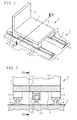
- test carriage 1 is mounted horizontally displaceable on two parallel aligned and arranged horizontally on a surface 2 of a test field 3 guide rails 4.
- the test carriage 1 has four rail guide parts 5 which are arranged at the four corners of the test carriage 1 and in each case engage in a positive engagement with the associated guide rail 4.
- formations of the rail guide parts 5 each encompass parallel to the surface 2 of the test field 3 projecting thickened rail heads of the guide rails. 4
- a cargo platform 6 with a flat loading surface 7 is mounted on the rail guide parts 5 via air spring devices 8 shown only schematically.
- the air spring devices 8 allow an almost torque-free displacement of the charge platform 6 in the vertical direction relative to the rail guide parts 5 and thus to the test field 3 and the guide rails 4 arranged thereon.
- an impeller 10 is arranged so that the impeller 10 unrolls on a displacement of the test carriage 1 in the horizontal direction along the guide rails 4 on the surface 2 of the test field 3.
- the impeller 10 has an irregular circumferential contour with differently configured and radially projecting protrusions 11.
- charge units On the loading surface 7 of the cargo platform 6 can in the Figures 1 and 2 Not shown, charge units arranged and fixed with the measures provided for the respective inspection charge securing means.
- charge units On the loading surface 7 of the charge platform 6 and on a vertically projecting rear wall 12 of the charge platform 6, numerous sensors, also not shown, can be arranged with which the forces exerted by the charge units on the charge platform 6 on the loading surface 7 and on the rear wall 12 during the forces Performing a test procedure can be measured and provided for a subsequent evaluation.
- the behavior of the charge units on the loading surface 7 of the charge platform 6 can be recorded during the performance of a test procedure.
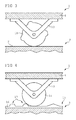
- FIG. 3 is the one in the Figures 1 and 2 shown test carriage 1 shown in an enlarged partial view in an area around the impeller 10.
- the impeller 10 is rotatably mounted on the charge platform 6 via a bow-shaped holding device 13 at a predetermined distance from the underside 9 of the charge platform 6.
- the impeller 10 forms, together with the holding device 13, the first deflection part.
- the flat surface 2 of the test field 3 forms the second deflection part, which cooperates with the first deflection part and forces a vertical displacement of the charge platform 6 during a horizontal displacement of the test carriage 1 over the surface 2 of the test field 3.
- the holding device 13 and the impeller 10 may be made, for example, from a light metal or from a sufficiently mechanically durable plastic, so that the weight of the test carriage 1 is not significantly increased by the attachment of the first deflection part on the loading platform 6.
- FIG. 4 is also schematically a different configuration of the first deflection part and the second deflection part of a in the Figures 1 and 2 shown testing device shown.
- the impeller 14 has a circular peripheral contour.
- On the surface 2 of the test field 3 is in the horizontal direction parallel to the Guide rails 4, a second deflection member 15 with an upwardly projecting from the surface 2 of the test field 3 deflection contour 16 set.
- the deflection contour 16 provided with irregularly shaped elevations 17 forces a vertical displacement of the impeller 10 rolling over the deflection contour 16 during a horizontal displacement of the test carriage 1 along the guide rails 4. In this way, an irregular vertical deflection of the charge platform 6 relative to the planar surface 2 can take place of the test field 3 are forced.
- the deflection contour 16 of the second deflection part 15 can extend over a complete diameter of the test field 3, so that irregular deflections over the entire length of the deflection contour 16 can be generated distributed and the irregular deflections are not limited to a circumference of the impeller 10.
- the second deflection part 15 extends over the entire travel path of the test carriage 1 on the guide rails 4. It is also possible for the second deflection part 15 to cover a sufficiently large area of the test field 3 in a line-shaped manner, but no significant vertical displacement of the charge platform 6 takes place at a distance from the second deflection part 15, while cooperation between the first deflection part arranged on the charge platform 6 and the first deflection part 6 a corresponding vertical deflection of the charge platform 6 is forced on the test field at least in an area in the vicinity of the guide rails 4 arranged second deflection part.
- the second deflection part 15 can either be arranged and fixed parallel to the guide rails 4 on the surface 2 of the test field 3 as a separate component. It is also possible that the second deflection part 15 is formed as part of a guide rail 4 or the two guide rails 4.
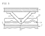
- FIG. 5 is merely an example of another embodiment of the deflection device of the test carriage 1 shown.
- a laterally projecting guide pin 18 is fixed on the holding device 13 which is fixed to the underside 9 of the loading platform 6, a laterally projecting guide pin 18 is fixed.
- the guide pin 18 is in engagement with a Auslenkungsnut 19 which is fixed in a rail-shaped second deflection member 20 parallel to the guide rails 4 on the surface 2 of the test field 3.
- the second deflection part 20 can also be a suitably designed section of a guide rail 4.
- the guide pin 18 may also be provided a rotatably mounted guide roller and are in engagement with the Auslenkungsnut 19.
Abstract
Eine Prüfvorrichtung für transportierbare Ladungseinheiten weist einen auf einem Prüffeld (3) horizontal verlagerbaren Prüfschlitten (1) auf, der eine Ladungsplattform (6) und eine Führungseinrichtung aufweist, die den Prüfschlitten (1) auf dem Prüffeld (3) abstützt. Die Ladungsplattform (6) ist vertikal verlagerbar an der Führungseinrichtung gelagert und an der Ladungsplattform (6) ist ein erstes Auslenkungsteil angeordnet, dass mit einem relativ zu dem Prüffeld (3) festgelegten zweiten Auslenkungsteil (15, 20) zusammenwirkt, um eine vertikale Auslenkung der Ladungsplattform (6) während einer horizontalen Verlagerung des Prüfschlittens (1) auf dem Prüffeld (3) zu bewirken. Das erste Auslenkungsteil kann eine Rolle mit einer in Umfangsrichtung profilierten Mantelfläche sein. Das zweite Auslenkungsteil (15) kann eine horizontal angeordnete Auslenkkontur (16) aufweisen, die eine Auslenkung des ersten Auslenkungsteils während einer horizontalen Verlagerung des Prüfschlittens (1) bewirkt. Die Auslenkkontur kann durch eine Auslenknut (19) gebildet sein, mit welcher das erste Auslenkungsteil in Eingriff steht. Die Ladungsplattform (6) ist über Luftfedereinrichtungen (8) an der Führungseinrichtung gelagert. Die Führungseinrichtung weist mindestens ein Schienenführungsteil (5) auf, welches mit einer auf dem Prüffeld (3) verlaufenden Führungsschiene (4) zusammenwirkt.A test device for transportable load units has a test carriage (1) which can be displaced horizontally on a test field (3), which has a loading platform (6) and a guide device which supports the test carriage (1) on the test field (3). The charge platform (6) is mounted vertically displaceably on the guide device and on the charge platform (6) a first deflection part is arranged, which interacts with a relative to the test field (3) fixed second deflection part (15, 20) to a vertical deflection of the Charge platform (6) during a horizontal displacement of the test carriage (1) on the test field (3) to effect. The first deflection part may be a roller with a circumferential surface profiled in the circumferential direction. The second deflection part (15) may have a horizontally arranged deflection contour (16), which causes a deflection of the first deflection part during a horizontal displacement of the test carriage (1). The Auslenkkontur can be formed by a Auslenknut (19), with which the first deflection part is engaged. The charge platform (6) is mounted on the guide device via air spring devices (8). The guide device has at least one rail guide part (5) which cooperates with a guide rail (4) extending on the test field (3).
Description
Die Erfindung betrifft eine Prüfvorrichtung für transportierbare Ladungseinheiten mit einem auf einem Prüffeld in einer ersten Bewegungsrichtung verlagerbaren Prüfschlitten, der eine Ladungsplattform und eine Führungseinrichtung aufweist, die den Prüfschlitten auf dem Prüffeld abstützt.The invention relates to a test device for transportable load units with a displaceable on a test field in a first direction of movement test carriage having a charge platform and a guide device which supports the test carriage on the test field.
Verpackte oder unverpackte Transportgüter können zu einzelnen formstabilen oder eine flexible bzw. veränderbare Formgebung aufweisende Ladungseinheiten zusammengestellt werden. Die einzelnen Ladungseinheiten können ihrerseits auf Paletten angeordnet sein. Die Transportgüter werden für einen Transportvorgang in einem Laderaum eines Transportmittels gelagert. Während eines Transports ist es zweckmäßig und oftmals notwendig, die Transportgüter in dem Laderaum zuverlässig zu fixieren und mit geeigneten Mitteln zu gewährleisten, dass die Transportgüter während des Transports nicht beschädigt werden und auch nicht das Transportmittel beschädigen. So wird beispielsweise in der Straßenverkehrsordnung gefordert, dass die Ladung einschließlich der verwendeten Geräte zur Ladungssicherung sowie Ladeeinrichtungen so zu verstauen und zu sichern sind, dass sie selbst bei Vollbremsung oder plötzlicher Ausweichbewegung nicht verrutschen, umfallen, hin- und herrollen, herabfallen oder vermeidbaren Lärm erzeugen können.Packaged or unpackaged transport goods can be put together to individual dimensionally stable or flexible or changeable shaping having charge units. The individual load units can in turn be arranged on pallets. The goods to be transported are stored for a transport process in a loading space of a means of transport. During transport, it is expedient and often necessary to reliably fix the transported goods in the hold and to ensure by suitable means that the transported goods are not damaged during transport and also do not damage the means of transport. Thus, for example, the Road Traffic Act requires that the cargo, including the devices used for securing cargo and charging devices, be stowed away and secured in such a way that they do not slip, fall over, roll back and forth, fall down or produce avoidable noise even during emergency braking or sudden evasive movement can.
Während eines Transports wirken üblicherweise zahlreiche Bewegungskräfte auf das Transportmittel und damit auf den Laderaum und die darin befindlichen Ladungseinheiten ein. Der Laderaum wird während des Transports in verschiedenen Richtungen beschleunigt und abgebremst. Zusätzlich wirken oftmals Vibrationen und Erschütterungen sowie Stöße auf den Laderaum und die Ladungseinheiten ein. Einzelne Ladungseinheiten können während des Transports unbeabsichtigt verlagert werden oder verrutschen. Im Falle einer plötzlichen Verlagerung können Kräfte und Momente auf das Transportmittel ausgeübt werden und die Transportsicherheit beeinträchtigt werden. Mit Hilfe von geeigneten Ladungssicherungsmitteln wie beispielsweise Spanngurten oder Zurrmitteln können Ladungseinheiten in dem Laderaum festgelegt und gegen ein unbeabsichtigtes Verrutschen gesichert werden.During transport, usually numerous movement forces act on the means of transport and thus on the hold and the charge units therein. The cargo space is accelerated and decelerated during transport in different directions. In addition, vibrations and shocks as well as impacts on the cargo hold and the cargo units often occur. Individual cargo units may be inadvertently displaced or slipped during transport. In the event of a sudden displacement, forces and moments can be exerted on the means of transport and transport safety can be impaired. With the help of suitable load securing means such as straps or lashing cargo units can be set in the hold and secured against accidental slipping.
Um die Verkehrssicherheit zu erhöhen wurden Normen und Vorschriften entwickelt, die für unterschiedliche Ladungseinheiten eine jeweils als notwendig erachtete und geeignete Ladungssicherungen während eines Transportvorgangs vorgeben. Ein Transporteur muss für die von ihm transportierten Ladungseinheiten eine ausreichende Ladungssicherung gewährleisten, was üblicherweise durch die Einhaltung der betreffenden Vorschriften erfüllt werden kann.In order to increase traffic safety, standards and regulations have been developed which specify for each load unit a suitable load securing device during transport. A transporter must ensure adequate cargo securing for the cargo units it transports, which can usually be achieved by complying with the relevant requirements.
Um zu ermitteln und zu überprüfen, welche Ladungssicherungen für welche Ladungseinheiten geeignet und notwendig sind, wurden verschiedene Prüfverfahren und Prüfvorrichtungen entwickelt. Mit einer in geeigneter Weise durchgeführten Prüfung kann für einzelne Ladungseinheiten der Nachweise einer ausreichenden Ladungssicherheit erbracht werden. Die einzelnen Prüfvorrichtungen sind konstruktiv aufwendig und die Durchführung einzelner Prüfungen kostenintensiv. Zudem bestehen für einige aus der Praxis bekannte Prüfverfahren erhebliche Zweifel daran, ob mit diesen Prüfverfahren ein zuverlässiger und aussagekräftiger Nachweis erbracht werden kann.In order to determine and check which load securing devices are suitable and necessary for which load units, various test methods and test devices have been developed. With a suitably carried out test can for individual charge units evidence of sufficient cargo safety. The individual test devices are structurally complex and the implementation of individual tests costly. In addition, for some of the test methods known from practice, there are considerable doubts as to whether a reliable and meaningful proof can be provided by these test methods.
Aus der Praxis sind beispielsweise Wagen oder Schlitten bekannt, auf denen einzelne Ladungseinheiten angeordnet werden können. Die Wagen oder Schlitten werden horizontal über ein ebenes Prüffeld verlagert, wobei horizontale Beschleunigungskräfte auf die Ladungseinheiten einwirken und das Verhalten der Ladungseinheiten in Abhängigkeit von den einwirkenden Beschleunigungskräften untersucht werden kann. Derartige Wagen oder Schlitten können jedoch ausschließlich horizontal einwirkende Beschleunigungskräfte und keine vertikalen Stöße oder Vibrationen erzeugen, die bei tatsächlichen Ladungstransporten unvermeidbar auftreten und oftmals einen ganz erheblichen Einfluss auf die Ladungssicherheit ausüben.From practice, for example, carriages or carriages are known on which individual load units can be arranged. The carriages or carriages are moved horizontally over a flat test field, with horizontal acceleration forces acting on the charge units and the behavior of the charge units depending on the applied acceleration forces can be examined. However, such carriages or carriages can only produce horizontally acting acceleration forces and no vertical shocks or vibrations that inevitably occur in actual charge transport and often have a very significant impact on cargo safety.
Es sind auch Rütteltische und Vibrationsprüfstände bekannt, bei denen eine Ladungseinheit vorgebbaren Vibrationen und Erschütterungen ausgesetzt werden kann, um das Verhalten der Ladungseinheit unter diesen Bedingungen zu untersuchen. Es hat sich jedoch gezeigt, dass kurzzeitige Krafteinwirkungen, wie sie durch Vibrationen oder Stöße erzeugt werden können, ebenfalls keine zuverlässigen Rückschlüsse auf die Ladungssicherheit bei realistischen Transportbedingungen ermöglichen.Vibrating tables and vibration test stands are also known in which a unit of load can be subjected to predeterminable vibrations and shocks in order to investigate the behavior of the unit under these conditions. However, it has been shown that short-term force effects, such as can be generated by vibrations or shocks, also do not allow reliable conclusions on the cargo security under realistic transport conditions.
Die im Straßenverkehr erforderliche und vorausgesetzte Ladungssicherheit wird deshalb in der Praxis oftmals durch realitätsnahe Fahrversuche ermittelt und überprüft, wobei ein mit Ladungseinheiten beladener Lastkraftwagen eine vorgegebene Streckenführung mit einer vorgegebenen Geschwindigkeit abfährt und das Verhalten der Ladungseinheiten in dem Laderaum untersucht wird, während die bei der Testfahrt erzeugten Beschleunigungskräfte und Erschütterungen auf den Laderaum einwirken. Die Durchführung solcher Testfahrten ist auch wegen der erforderlichen Messvorrichtungen mit erheblichen Kosten verbunden. Zudem lassen sich die verschiedenen Testfahrten nur bedingt vergleichen, da die Testergebnisse beispielsweise von den während des Testvorgangs herrschenden Umgebungsbedingungen und von einzelnen Testfahrern und Testfahrten abhängen können.Therefore, in practice, the required and required load safety on the road is often determined and checked by realistic driving tests, with a truck loaded with cargo units launches a predetermined route with a predetermined speed and the behavior of the cargo units is examined in the hold while the test drive acting acceleration forces and vibrations acting on the cargo space. Carrying out such test drives is also associated with considerable costs because of the required measuring devices. In addition, the various test drives can only be compared to a limited extent since the test results can depend, for example, on the ambient conditions prevailing during the test procedure and on individual test drivers and test drives.
Im Gegensatz dazu bieten Prüfvorrichtungen der eingangsgenannten Gattung, bei denen ein Prüfschlitten auf einem ebenen Prüffeld horizontal verlagerbar ist, oftmals die Möglichkeit, präzise und reproduzierbare Versuchsergebnisse zu ermitteln. Die während einer Bewegung des Prüfschlittens auf dem Prüffeld erzeugten horizontalen Beschleunigungskräfte können jedoch nicht alle mechanischen Beanspruchungen simulieren, denen die Ladungseinheiten während eines Transports mit einem Transportmittel ausgesetzt sind. So hat sich beispielsweise gezeigt, dass eine Ladungseinheit, die gleichzeitig auch Vibrationen und stoßartigen Erschütterungen ausgesetzt ist, bereits bei geringeren Beschleunigungskräften verrutscht, als es ohne Vibrationen und Erschütterungen der Fall wäre.In contrast, test devices of the aforementioned type, in which a test carriage is horizontally displaceable on a flat test field, often offer the possibility of determining precise and reproducible test results. However, the horizontal acceleration forces generated during a movement of the test carriage on the test field can not simulate all the mechanical stresses to which the load units are exposed during transport with a means of transport. For example, it has been shown that a cargo unit that is exposed simultaneously to vibrations and shock-like vibrations, even with lower acceleration forces slip, as it would be without vibration and shocks.
Es wird deshalb als eine Aufgabe der vorliegenden Erfindung angesehen, eine Prüfvorrichtung der eingangs genannten Gattung so auszugestalten, dass mit möglichst geringem Aufwand möglichst realitätsnahe und aussagekräftige Prüfungen zur Ladungssicherheit von Ladungseinheiten durchgeführt werden können.It is therefore regarded as an object of the present invention to design a test apparatus of the type mentioned in the introduction in such a way that the most realistic and meaningful tests possible for the cargo safety of cargo units can be carried out with as little effort as possible.
Diese Aufgabe wird erfindungsgemäß dadurch gelöst, dass die Ladungsplattform senkrecht zu der ersten Bewegungsrichtung verlagerbar an der Führungseinrichtung gelagert ist, und dass an der Ladungsplattform ein erstes Auslenkungsteil angeordnet ist, dass mit einem relativ zu dem Prüffeld festgelegten zweiten Auslenkungsteil zusammenwirkt, um während einer in der ersten Bewegungsrichtung erfolgenden Verlagerung des Prüfschlittens auf dem Prüffeld eine senkrecht zu der ersten Bewegungsrichtung erfolgende Auslenkung der Ladungsplattform zu bewirken. Das erste Auslenkungsteil und das zweite Auslenkungsteil bilden dabei eine Auslenkungseinrichtung, die während einer üblicherweise horizontalen Verlagerung des Prüfschlittens eine vertikale Auslenkung der Ladungsplattform herbeiführen, so dass gleichzeitig horizontale Beschleunigungskräfte und vertikale Beschleunigungskräfte auf eine auf der Ladungsplattform befindliche Ladungseinheit einwirken können. Im Vergleich zu herkömmlichen Rütteltischen kann der Prüfschlitten horizontal über weite Strecken verlagert werden, sodass realistische Beschleunigungsvorgänge während eines Prüfvorgangs simuliert werden können. Durch die Auslenkungseinrichtung können gleichzeitig Vibrationen und Erschütterungen in vertikaler Richtung erzeugt werden, was bei herkömmlichen Prüfwaagen oder Prüfschlitten nicht oder nur mit einem erheblichen konstruktiven Aufwand möglich ist.This object is achieved in that the charge platform is mounted perpendicular to the first direction of movement displaced on the guide means, and that on the charge platform, a first deflection member is arranged that cooperates with a fixed relative to the test field second deflection member to during a in the first movement direction displacement of the test carriage on the test field to effect a perpendicular to the first direction of movement taking place deflection of the charge platform. In this case, the first deflection part and the second deflection part form a deflection device which, during a usually horizontal displacement of the test carriage, brings about a vertical deflection of the charge platform, so that horizontal acceleration forces and vertical acceleration forces can simultaneously act on a charge unit located on the charge platform. Compared to conventional vibration tables, the test carriage can be moved horizontally over long distances, so that realistic acceleration processes can be simulated during a test procedure. By the deflection device vibrations and vibrations in the vertical direction can be generated simultaneously, which is not or conventional test scales or test carriage only possible with a considerable design effort.
Für viele Anwendungsfälle ist es zweckmäßig, die erste Bewegungsrichtung und damit die Richtung der Verlagerung des Prüfschlittens auf dem Prüffeld horizontal vorzugeben und eine senkrecht dazu und damit vertikale Auslenkung der Ladungsplattform herbeizuführen, so dass im Folgenden oftmals auch sprachlich vereinfachend eine horizontale Verlagerung des Prüfschlittens und eine vertikale Auslenkung bzw. Verlagerung der Ladungsplattform beschrieben wird, ohne dadurch die Erfindung auf diese Ausrichtungen beschränken zu wollen. Die Auslenkung der Ladungsplattform muss nicht notwendigerweise senkrecht zu einer ersten Bewegungsrichtung des Prüfschlittens erfolgen, sondern lediglich eine senkrecht zu der ersten Bewegungsrichtung des Prüfschlittens gerichtete Komponente aufweisen. So könnte die Auslenkung der Ladungsplattform auch in einem vorgegebenen konstanten oder sich während des Prüfvorgangs verändernden Winkel zur ersten Bewegungsrichtung des Prüfschlittens erfolgen.For many applications, it is expedient to specify the first direction of movement and thus the direction of the displacement of the test carriage on the test field horizontally and bring about a vertical and thus vertical deflection of the charge platform, so that often linguistically simplifying a horizontal displacement of the test carriage and a vertical deflection or displacement of the charge platform is described, without thereby limiting the invention to these orientations. The deflection of the charge platform does not necessarily have to be perpendicular to a first direction of movement of the test carriage, but merely to have a component directed perpendicular to the first direction of movement of the test carriage. Thus, the deflection of the charge platform could also take place in a predetermined constant angle or during the test procedure changing angle to the first direction of movement of the test carriage.
So kann es beispielsweise zweckmäßig sein, die erste Bewegungsrichtung geneigt zur Erdoberfläche vorzugeben, so dass sich der Prüfschlitten aufgrund des Eigengewichts und der Erdanziehung selbsttätig in Bewegung versetzt und in einen tiefer gelegenen Bereich des Prüffelds gleitet. Durch eine Vorgabe des Neigungswinkels und des Verlaufs der ersten Bewegungsrichtung kann die gegebenenfalls sich verändernde Beschleunigung des Prüfschlittens während seiner Verlagerung in der ersten Bewegungsrichtung vorgegeben werden.Thus, it may be expedient, for example, to predetermine the first direction of movement inclined to the earth's surface, so that the test carriage automatically starts to move due to its own weight and the gravitational pull and slides into a deeper area of the test field. By specifying the inclination angle and the course of the first movement direction, the possibly changing acceleration of the test carriage during its displacement in the first direction of movement can be specified.
Es ist ebenfalls möglich, dass das Prüffeld keine vollständig ebene Oberfläche aufweist und sich die erste Bewegungsrichtung während des Prüfvorgangs verändert. So kann beispielsweise entlang einer über das Prüffeld verlaufenden Trajektorie für den Prüfschlitten der Neigungswinkel dieser Trajektorie relativ zu einer horizontalen Referenzlinie unterschiedlich vorgegeben sein.It is also possible that the test field does not have a completely flat surface and the first direction of movement changes during the test procedure. For example, the inclination angle of this trajectory relative to a horizontal reference line can be predetermined differently along a trajectory extending over the test field for the test carriage.
Gemäß einer Ausgestaltung des Erfindungsgedankens ist vorgesehen, dass das erste Auslenkungsteil eine Rolle mit einer in Umfangsrichtung profilierten Mantelfläche aufweist. Das erste Auslenkungsteil kann auch ein Rad oder eine Scheibe mit einer nicht kreisförmigen Umfangskontur sein. Eine Oberfläche des Prüffelds kann das zweite Auslenkungsteil bilden, auf dem die an der Ladungsplattform festgelegte Rolle während einer Verlagerung des Prüfschlittens abrollt. Die Rolle kann in Umfangsrichtung regelmäßig oder auch unregelmäßig angeordnete Ausformungen und Vertiefungen aufweisen, sodass die mit der Rolle verbundene Ladungsplattform während einer in der ersten Bewegungsrichtung beispielsweise horizontal erfolgenden Verlagerung des Prüfschlittens in einer dazu senkrechten Richtung und damit beispielsweise vertikal angehoben und abgesenkt wird. Auf diese Weise kann äußerst kostengünstig eine vertikale Verlagerung der Ladungsplattform während einer horizontalen Bewegung erzwungen werden.According to one embodiment of the inventive concept, it is provided that the first deflection part has a roller with a circumferential surface profiled in the circumferential direction. The first deflection member may also be a wheel or disc having a non-circular peripheral contour. One surface of the test field may form the second deflection part on which the roller fixed on the loading platform rolls during a displacement of the test carriage. The roller may have regularly or irregularly arranged formations and depressions in the circumferential direction, so that the charge platform connected to the roller is raised and lowered during a displacement of the test carriage, for example horizontally in the first direction of movement, in a direction perpendicular thereto and thus, for example, vertically. In this way, a vertical displacement of the cargo platform during a horizontal movement can be enforced extremely cost.
Die in Umfangsrichtung an dem Rad oder an der Rolle angeordneten Ausformungen und Vertiefungen können eine unterschiedliche Formgebung aufweisen, sodass jeweils unterschiedliche vertikale Beschleunigungskräfte auf die Ladungsplattform ausgeübt werden.The circumferentially on the wheel or on the roller arranged protrusions and depressions may have a different shape, so that in each case different vertical acceleration forces are exerted on the cargo platform.
Es ist ebenfalls möglich, dass das zweite Auslenkungsteil eine sich in der ersten Bewegungsrichtung erstreckende und in vertikaler Richtung ausgebildete Auslenkkontur aufweist, die eine Auslenkung des ersten Auslenkteils während einer Verlagerung des Prüfschlittens in der ersten Bewegungsrichtung bewirkt. Das erste Auslenkteil kann eine Rolle oder ein Rad mit einer kreisförmigen Umfangskontur aufweisen, so dass während einer beispielsweise horizontalen Verlagerung des Prüfschlittens das erste Auslenkungsteil auf der Auslenkkontur des zweiten Auslenkungsteils abrollt. Es ist ebenfalls denkbar, dass das erste Auslenkungsteil eine beispielsweise nockenförmige Gleitfläche aufweist, die während einer horizontalen Verlagerung des Prüfschlittens auf der Auslenkkontur entlanggeführt wird und eine entsprechende vertikale Auslenkung der Ladungsplattform bewirkt. Zu diesem Zweck weist die Auslenkkontur eine Auslenkoberfläche auf, über die das erste Auslenkungsteil hinweg bewegt wird.It is likewise possible for the second deflection part to have a deflection contour extending in the first movement direction and formed in the vertical direction, which causes a deflection of the first deflection part during a displacement of the test carriage in the first direction of movement. The first deflection part can have a roller or a wheel with a circular peripheral contour, so that during a horizontal displacement, for example, of the test carriage, the first deflection part rolls on the deflection contour of the second deflection part. It is also conceivable that the first deflection part has an example cam-shaped sliding surface, which is guided along during a horizontal displacement of the test carriage on the Auslenkkontur and causes a corresponding vertical deflection of the charge platform. For this purpose, the deflection contour has a deflection surface over which the first deflection part is moved.
Bei einer derartigen Ausgestaltung der Auslenkungseinrichtung mit einer Auslenkoberfläche können vor allem senkrecht zu der ersten Bewegungsrichtung von dem Prüffeld weg gerichtete Stöße sowie Vibrationen erzeugt werden. Durch das Eigengewicht des Prüfschlittens sowie durch das Gewicht der auf der Ladungsplattform angeordneten Ladungseinheiten wird die Ladungsplattform bei einer Verlagerung des Prüfschlittens über ein horizontal ausgerichtetes Prüffeld nach jeder vertikal nach oben gerichteten Auslenkung wieder nach unten zu dem Prüffeld hin beschleunigt.In such an embodiment of the deflection device with a deflection surface, shocks and vibrations directed away from the test field, in particular perpendicular to the first direction of movement, can be generated. As a result of the weight of the test carriage and the weight of the charge units arranged on the charge platform, the loading platform is accelerated downwards again to the test field during a displacement of the test carriage via a horizontally oriented test field after each vertically upward deflection.
Um sowohl nach oben wie auch nach unten gerichtete vertikale Beschleunigungskräfte auf die Ladungsplattform ausüben zu können ist vorgesehen, dass die Auslenkkontur durch eine Auslenkungsnut gebildet wird, mit der das erste Auslenkteil in Eingriff steht. Das erste Auslenkungsteil kann beispielsweise einen seitlich vorspringenden und in die Auslenkung tragenden Führungszapfen aufweisen. Der Führungszapfen folgt während einer horizontalen Verlagerung dem Verlauf der Auslenkungsnut und wird dabei entsprechend dem Verlauf der Auslenkungsnut abwechselnd nach oben und nach unten verlagert bzw. beschleunigt.For both upward and downward vertical acceleration forces on the cargo platform to be able to exercise, it is provided that the Auslenkkontur is formed by a Auslenkungsnut with which the first Auslenkteil is engaged. The first deflection part may, for example, have a laterally projecting and bearing in the deflection guide pin. The guide pin follows during a horizontal displacement of the course of the Auslenkungsnut and is thereby displaced alternately up and down according to the course of the Auslenkungsnut or accelerated.
Es ist grundsätzlich möglich und insbesondere bei großen Prüfschlitten sowie bei Ladungseinheiten mit einem großen Eigengewicht zweckmäßig, dass mehrere erste Auslenkungsteile über eine Unterseite der Ladungsplattform verteilt an der Ladungsplattform angeordnet sind. Die ersten Auslenkungsteile und die mit den ersten Auslenkungsteilen zusammenwirkenden zweiten Auslenkungsteile können synchronisiert und aufeinander abgestimmt sein, sodass die Ladungsplattform durch die mehreren Auslenkungsteile gleichmäßig vertikal ausgelenkt wird. Es ist jedoch ebenso möglich und im Hinblick auf eine möglichst realistische Durchführung des Prüfvorgangs vorteilhaft, dass mehrere Auslenkungsteile mit einer unterschiedlichen, bzw. nicht relativ zueinander synchronisierten Formgebung an der Ladungsplattform beabstandet zueinander angeordnet sind, sodass an unterschiedlichen Bereichen der Ladungsplattform verschiedene vertikale Auslenkungen erzeugt werden können. Auf diese Weise können nahezu aus beliebiger Richtung auf die Ladungsplattform einwirkende Beschleunigungskräfte und Momente erzeugt werden.In principle, it is possible, and particularly in the case of large test carriages and in the case of load units with a large dead weight, for a plurality of first deflection parts to be distributed over an underside of the charge platform to the charge platform. The first deflection parts and the second deflection parts interacting with the first deflection parts can be synchronized and matched to one another, so that the charge platform is deflected uniformly vertically by the plurality of deflection parts. However, it is also possible and with regard to the most realistic possible implementation of the test procedure advantageous that a plurality of deflection parts are arranged with a different, or not synchronized relative to each other shape spaced on the charge platform to each other, so that different vertical deflections are generated at different areas of the charge platform can. In this way, acceleration forces and moments acting on almost any direction on the charge platform can be generated.
Es ist vorgesehen, dass die Ladungsplattform über Luftfedern an der Führungseinrichtung gelagert ist. Durch die Verwendung von Luftfedern werden bei einer Auslenkung der Ladungsplattform relativ zu der Führungseinrichtung lediglich geringe Momente auf die Ladungsplattform übertragen. Umgekehrt werden während der Durchführung eines Prüfvorgangs auch von der Plattform keine oder lediglich geringe Momente auf die Führungseinheit übertragen. Dadurch kann die Führungseinheit deutlich kleiner und leichter als bei Verwendung anderer Lagereinrichtungen ausgeführt werden. Durch geeignete Führungselemente kann gewährleistet werden, dass die Luftfedern bei den horizontal auf den Prüfschlitten einwirkenden Beschleunigungskräften nicht übermäßig beansprucht werden.It is envisaged that the charge platform is mounted on the guide device via air springs. Due to the use of air springs, only slight moments are transmitted to the charge platform when the charge platform is deflected relative to the guide device. Conversely, during the execution of a test procedure, no or only small moments are transmitted from the platform to the guide unit. As a result, the guide unit can be made significantly smaller and lighter than when using other storage facilities. Suitable guide elements can be used to ensure that the air springs are not unduly stressed during the acceleration forces acting horizontally on the test carriage.
Um die horizontale Verlagerung des Prüfschlittens möglichst präzise vorgeben zu können ist vorgesehen, dass die Führungseinrichtung mindestens ein Schienenführungsteil aufweist, welches mit einer auf dem Prüffeld verlaufenden Führungsschiene zusammenwirkt. Es ist grundsätzlich möglich, dass der Prüfschlitten ein oder mehrere Seitenführungsteile aufweist, die seitlich vorspringen und mit einer ebenfalls seitlich neben der vorgesehenen horizontalen Bewegungsrichtung des Prüfschlittens verlaufenden Führungsschiene in Eingriff stehen.In order to be able to specify the horizontal displacement of the test carriage as precisely as possible, it is provided that the guide device has at least one rail guide part which cooperates with a guide rail extending on the test field. It is fundamentally possible for the test carriage to have one or more lateral guide parts which protrude laterally and engage with a guide rail also extending laterally next to the intended horizontal direction of movement of the test carriage.
Gemäß einer äußerst vorteilhaften Ausgestaltung des Erfindungsgedankens ist vorgesehen, dass zwei parallel nebeneinander angeordnete Führungsschienen auf dem Prüffeld angeordnet sind, und dass der Prüfschlitten an der Unterseite der Ladungsplattform angeordnete Schienenführungsteile entlang den Führungsschienen rollend oder gleitend verlagert werden kann. Die Schienenführungsteile können beispielsweise einen verdickten Schienenkopf der Führungsschienen umgreifen oder hintergreifen, um eine formschlüssige Lagerung des Prüfschlittens auf den Führungsschienen und dessen exakte Führung über das Prüffeld zu ermöglichen. Die Schienenführungsteile können weiterhin Rollen oder Gleitflächen aufweisen, um eine möglichst reibungsarme und leichtgängige Verlagerung des Prüfschlittens über die Führungsschienen zu begünstigen.According to an extremely advantageous embodiment of the inventive concept, it is provided that two guide rails arranged parallel to one another are arranged on the test field, and that the test carriage on the underside of the loading platform arranged rail guide parts along the guide rails can be moved rolling or sliding. The Rail guide parts, for example, engage around or engage behind a thickened rail head of the guide rails in order to enable a form-fitting mounting of the test carriage on the guide rails and its exact guidance over the test field. The rail guide parts may continue to have rollers or sliding surfaces in order to promote the lowest possible friction and smooth displacement of the test carriage on the guide rails.
Zweckmäßigerweise ist vorgesehen, dass die Prüfvorrichtung eine Antriebseinrichtung aufweist, die mit dem Prüfschlitten verbunden ist. Für einfache Prüfvorgänge ist es grundsätzlich denkbar, dass der Prüfschlitten entweder manuell angeschoben oder aber auf eine schräge Ebene gelagert ist und auf Grund seines Eigengewichts mit zunehmender Geschwindigkeit die schräge Ebene hinab gleitet oder hinab rollt. Um möglichst reproduzierbare horizontale Verlagerungen des Prüfschlittens zu ermöglichen, bei denen die jeweils auftretenden horizontalen Beschleunigungskräfte präzise vorgegeben werden können, ist es vorteilhaft, dass der Prüfschlitten mit einer steuerbaren oder regelbaren Antriebseinrichtung verbunden ist und über diese Antriebseinrichtung kontrolliert verlagert werden kann.Appropriately, it is provided that the test apparatus has a drive device which is connected to the test carriage. For simple test procedures, it is conceivable in principle that the test carriage is either pushed manually or stored on an inclined plane and due to its own weight with increasing speed, the inclined plane slides down or rolls down. In order to enable the most reproducible horizontal displacements of the test carriage, in which the horizontal acceleration forces occurring in each case can be precisely specified, it is advantageous that the test carriage is connected to a controllable or controllable drive means and controlled by this drive means can be moved.
Erfindungsgemäß ist vorgesehen, dass die Antriebseinrichtung eine Seiltriebeinrichtung mit einem Antriebsseil aufweist, dass mit dem Prüfschlitten verbunden ist. Die Seiltriebeinrichtung kann beispielsweise eine Seiltrommel aufweisen, auf welche das mit dem Prüfschlitten verbundene Antriebsseil aufgewickelt werden kann, wobei durch die Verkürzung des losen und noch nicht aufgewickelten Endes des Antriebsseils der Prüfschlitten gezogen und beschleunigt wird. Zweckmäßigerweise ist vorgesehen, dass die Seiltriebeinrichtung zwei Antriebsseile aufweist, die an entgegengesetzten Stirnseiten mit dem Prüfschlitten verbunden sind und in entgegengesetzte Richtungen verlagert, bzw. aufgerollt werden können. Durch eine synchronisierte Betätigung der beiden Antriebsseile kann eine Beschleunigung und Verzögerung des Prüfschlittens in der durch die Führungseinrichtung vorgegebenen Verlagerungsrichtung vorgegeben werden. Auf diese Weise kann der Prüfschlitten auf den Führungsschienen in beide Richtungen verlagert und nach Belieben beschleunigt bzw. verzögert werden.According to the invention, it is provided that the drive device has a cable drive device with a drive cable that is connected to the test carriage. The cable drive device may, for example, have a cable drum on which the drive cable connected to the test carriage can be wound up, the trolley being shortened by the loose and not yet wound end of the drive cable pulled and accelerated. Appropriately, it is provided that the cable drive device comprises two drive cables, which are connected at opposite end sides with the test carriage and displaced in opposite directions, or can be rolled up. By synchronized actuation of the two drive cables, an acceleration and deceleration of the test carriage can be predetermined in the direction of displacement predetermined by the guide device. In this way, the test carriage can be displaced on the guide rails in both directions and accelerated or delayed as desired.
Es ist ebenfalls möglich und für verschiedene Prüfungsvorgänge zweckdienlich, dass die Antriebseinrichtung einen doppelt bzw. in zwei entgegengesetzte Richtungen wirkenden Hydraulikzylinder oder zwei in entgegengesetzte Richtungen betätigbare Hydraulikzylinder aufweist, die über eine Kopplungseinrichtung mit einer Stirnfläche des Prüfschlittens verbunden sind.It is also possible and useful for various testing procedures that the drive means comprise a double or two opposing hydraulic cylinder or two oppositely actuable hydraulic cylinders connected by a coupling means to an end surface of the test carriage.
Um zu vermeiden, dass über die Antriebseinrichtung unerwünschte Momente auf den Prüfschlitten übertragen werden, kann vorgesehen sein, dass die Antriebseinrichtung in vertikaler Richtung beabstandet zu einer Ladefläche der Ladungsplattform mit dem Prüfschlitten verbunden ist. So kann beispielsweise an einer der Antriebseinrichtung zugeordneten Stirnseite eine Halteeinrichtung oder ein Halterahmen vorgesehen sein, welcher in vertikaler Richtung über die Ladefläche der Ladungsplattform vorspringt und an dem die Antriebseinrichtung beabstandet zu der Ladefläche angekoppelt werden kann. Durch einen in geeigneter Weise vorgegebenen vertikalen Versatz der Wirkverbindung der Antriebseinrichtung zu der Ladungsplattform können bei einer Beschleunigung des Prüfschlittens absichtlich Momente erzeugt werden, um die aus den Trägheitskräften resultierenden Momente teilweise oder vollständig zu kompensieren.In order to avoid that unwanted moments are transmitted to the test carriage via the drive device, it can be provided that the drive device is connected in the vertical direction at a distance to a loading surface of the cargo platform with the test carriage. Thus, for example, a holding device or a holding frame may be provided on an end face associated with the drive device, which protrudes in the vertical direction over the loading surface of the loading platform and on which the drive device can be coupled at a distance to the loading surface. By a suitable way predetermined vertical offset of the operative connection of the drive means to the charge platform can be intentionally generated at an acceleration of the test carriage moments to partially or completely compensate for the moments resulting from the inertial forces.
Um kontinuierlich regelmäßige Vibrationen und Erschütterungen auf die Ladungseinheiten ausüben zu können ist erfindungsgemäß vorgesehen, dass der Prüfschlitten mindestens einen Unwuchtmotor aufweist, mit welchem eine Schwingungsauslenkung der Ladungsplattform erzeugt werden kann. Ein geeigneter Unwuchtmotor kann mit ausreichender Leistung und gleichzeitig geringem Raumbedarf und Eigengewicht an dem Prüfschlitten angeordnet sein, sodass bei einem Betrieb des Unwuchtmotors die Ladungsplattform den durch den Unwuchtmotor erzeugten Vibrationen und Erschütterungen ausgesetzt ist. Auf diese Weise kann kostengünstig und mit geringem Gewicht eine regelmäßige Vibration und Erschütterung der auf dem Prüfschlitten befindlichen Ladungseinheiten simuliert werden. Die durch den Unwuchtmotor erzeugten Vibrationen und Erschütterungen können zusätzlich zu den mit der Auslenkungseinrichtung erzwungenen vertikalen Auslenkungen auf die Ladungsplattform und damit auf die darauf angeordneten Ladungseinheiten ausgeübt werden.In order to be able to exert continuous regular vibrations and shocks on the load units is inventively provided that the test carriage has at least one unbalance motor, with which a vibration deflection of the charge platform can be generated. A suitable unbalance motor can be arranged with sufficient power and at the same time small space requirement and dead weight on the test carriage, so that during operation of the unbalance motor, the charge platform is exposed to the vibrations and vibrations generated by the unbalance motor. In this way, a regular vibration and vibration of the charge units located on the test carriage can be simulated inexpensively and with low weight. The vibrations and vibrations generated by the unbalance motor can be exerted on the charge platform and thus on the charge units arranged thereon in addition to the vertical deflections forced by the deflection device.
Die Erfindung betrifft auch das Verfahren zur Durchführung eines Prüfvorgangs zur Ladungssicherheit von transportierbaren Ladungseinheiten, wobei ein Prüfschlitten auf einem Prüffeld in einer ersten Bewegungsrichtung verlagert wird. Erfindungsgemäß und mit Verweis auf die vorausgegangenen Ausführungen ist vorgesehen, dass die transportierbaren Ladungseinheiten auf einer an dem Prüfschlitten gelagerten Ladungsplattform angeordnet werden und die Ladungsplattform während der Durchführung des Prüfvorgangs senkrecht zu der ersten Bewegungsrichtung des Prüfschlittens ausgelenkt wird, um während der Durchführung des Prüfvorgangs sowohl horizontale als auch vertikale Beschleunigungskräfte auf eine auf der Ladungsplattform befindliche Ladungseinheit auszuüben.The invention also relates to the method for carrying out a test procedure for the load safety of transportable load units, wherein a test carriage is displaced on a test field in a first direction of movement. According to the invention and with reference to the preceding statements, it is provided that the transportable cargo units are arranged on a charge platform mounted on the test carriage and the charge platform is deflected during the conduct of the test process perpendicular to the first direction of movement of the test carriage to exert both horizontal and vertical acceleration forces on a charge platform located on the cargo platform during the conduct of the test process.
Um auch einen Einfluss der Ladungssicherung auf die Ladungssicherheit zu erfassen ist vorgesehen, dass eine auf der Ladungsplattform befindliche Ladungseinheit während der Durchführung des Prüfvorgangs mit mindestens einem Gerät zur Ladungssicherung auf der Ladungsplattform festgelegt ist.In order to also detect an influence of the load securing on the load safety, it is provided that a charge unit located on the charge platform is fixed with at least one load securing device on the charge platform during the execution of the test procedure.
Mit der erfindungsgemäßen Prüfvorrichtung können mit einfachen konstruktiven Mitteln und äußerst kostengünstig Prüfverfahren durchgeführt werden, bei denen die auf der Ladungsplattform angeordneten Ladungseinheiten horizontalen Beschleunigungen und gleichzeitig vertikalen Vibrationen und Erschütterungen ausgesetzt werden kann, um das Verhalten der Ladungseinheiten auf der Ladefläche der Ladungsplattform realitätsnah zu untersuchen und zu überprüfen. Die Prüfvorrichtung bietet die Möglichkeit der Anbringung von verschiedenen Sicherungsmitteln wie beispielsweise Zurrgurte oder Zurrketten, Sperrbalken oder Netze, mit denen einzelne oder mehrere Ladungseinheiten auf dem Prüfschlitten bzw. auf der Ladungsplattform zusätzlich festgelegt und gesichert werden können. Damit können nicht nur einzelne Ladungseinheiten und deren Verhalten, sondern auch die verschiedenen Möglichkeiten einer zusätzlichen Ladungssicherung untersucht werden.With the test device according to the invention can be carried out with simple design means and extremely inexpensive test methods in which the arranged on the charge platform charge units horizontal accelerations and simultaneously vertical vibrations and shocks can be exposed to the behavior of the cargo units on the back of the cargo platform to investigate realistic and to check. The test device offers the possibility of attaching various securing means such as lashing or lashing chains, barrier bars or networks, with which one or more load units on the test carriage or on the cargo platform can be additionally set and secured. Not only individual load units and their behavior, but also the different possibilities of additional load securing can be examined.
Nachfolgend werden einige Ausführungsbeispiele des Erfindungsgedankens näher erläutert, die in der Zeichnung dargestellt sind. Es zeigt:
-
Figur 1 -
Figur 2Figur 1Figur 1 -
Figur 3Figur 2 -
Figur 4Figur 3 , wobei ein abweichend ausgestaltetes erstes Auslenkungsteil an der Ladungsplattform mit einem ebenfalls abweichend ausgestalteten zweiten Auslenkungsteil auf dem Prüffeld zusammenwirkt, und -
Figur 5den Figuren 3 und 4 einer wiederum abweichend ausgestalteten Auslenkungsanordnung mit einem an der Ladungsplattform festgelegten ersten Auslenkungsteil, das formschlüssig mit einer auf dem Prüffeld festgelegten und sich horizontal erstreckenden Auslenkungsnut in Eingriff steht.
-
FIG. 1 a schematic and perspective view of a test carriage, which is mounted horizontally displaceable on two guide rails, -
FIG. 2 a schematic sectional view taken along the line II-II inFIG. 1 of inFIG. 1 shown test carriage in an area around the guide rails, -
FIG. 3 a schematic sectional view of a portion of the test carriage along the line III-III inFIG. 2 in that a first deflection part is arranged on the loading platform of the test carriage and interacts with a second deflection part defined on the test field, -
FIG. 4 a schematic sectional view according toFIG. 3 , wherein a differently designed first deflection part on the charge platform interacts with a likewise deviating designed second deflection part on the test field, and -
FIG. 5 a schematic sectional view according to theFIGS. 3 and 4 an in turn deviating designed deflection arrangement with a fixed to the charge platform first deflection member which is positively connected to a defined on the test field and extending horizontally Auslenkungsnut engaged.
Ein in den
Eine Ladungsplattform 6 mit einer ebenen Ladefläche 7 ist über lediglich schematisch dargestellte Luftfedereinrichtungen 8 an den Schienenführungsteilen 5 gelagert. Die Luftfedereinrichtungen 8 erlauben eine nahezu momentenfreie Verlagerung der Ladungsplattform 6 in vertikaler Richtung relativ zu den Schienenführungsteilen 5 und damit zu dem Prüffeld 3 und den darauf angeordneten Führungsschienen 4.A
An einer Unterseite 9 der Ladungsplattform 6 ist ein Laufrad 10 so angeordnet, dass das Laufrad 10 bei einer Verlagerung des Prüfschlittens 1 in horizontaler Richtung entlang den Führungsschienen 4 auf der Oberfläche 2 des Prüffelds 3 abrollt. Das Laufrad 10 weist eine unregelmäßige Umfangskontur mit unterschiedlich ausgestalteten und radial vorspringenden Ausformungen 11 auf. Wenn bei einer Verlagerung des Prüfschlittens 1 längs der Führungsschienen 4 und einem entsprechenden Abrollvorgang des Laufrads 10 eine radial vorspringende Ausformung 11 des Laufrads 10 über die Oberfläche 2 des Prüffelds 3 bewegt wird, erzwingt diese Ausformung 11 eine vertikale Auslenkung der Ladungsplattform 6. In Abhängigkeit von der horizontalen Verlagerungsgeschwindigkeit des Prüfschlittens 1 führt die Ausformung 11 des Laufrads 10 während eines Abrollvorgangs zu einer stoßartigen vertikalen Auslenkung der Ladungsplattform 6.On an
Auf der Ladefläche 7 der Ladungsplattform 6 können in den
Zusätzlich kann beispielsweise mit Filmkameras oder mit Hochgeschwindigkeitskameras das Verhalten der Ladungseinheiten auf der Ladefläche 7 der Ladungsplattform 6 während der Durchführung eines Prüfvorgangs aufgezeichnet werden.In addition, for example, with film cameras or with high-speed cameras, the behavior of the charge units on the
Es ist ebenfalls möglich, nach dem Abschluss eines Prüfvorgangs die auf der Ladefläche 7 der Ladungsplattform 6 angeordneten Ladungseinheiten auf mechanische Beanspruchungen und gegebenenfalls auf eine Beschädigung hin zu untersuchen.It is likewise possible, after completion of a test procedure, to examine the charge units arranged on the
In
Die Haltereinrichtung 13 und das Laufrad 10 können beispielsweise aus einem Leichtmetall oder aus einem ausreichend mechanisch beanspruchbaren Kunststoff hergestellt sein, sodass sich das Eigengewicht des Prüfschlittens 1 durch die Befestigung des ersten Auslenkungsteils an der Ladungsplattform 6 nicht nennenswert vergrößert.The holding
In
Die Auslenkungskontur 16 des zweiten Auslenkungsteils 15 kann sich über einen vollständigen Durchmesser des Prüffelds 3 erstrecken, so dass unregelmäßige Auslenkungen über die gesamte Länge der Auslenkungskontur 16 verteilt erzeugt werden können und die unregelmäßigen Auslenkungen nicht auf einen Umfang des Laufrads 10 beschränkt sind.The
Zweckmäßigerweise ist vorgesehen, dass sich das zweite Auslenkungsteil 15 über den gesamten Verfahrweg des Prüfschlittens 1 auf den Führungsschienen 4 erstreckt. Es ist ebenfalls möglich, dass das zweite Auslenkungsteil 15 einen ausreichend großen Bereich des Prüffelds 3 linienförmig abdeckt, aber beabstandet zu dem zweiten Auslenkungsteil 15 keine nennenswerte vertikale Verlagerung der Ladungsplattform 6 erfolgt, während durch ein Zusammenwirken des an der Ladungsplattform 6 angeordneten ersten Auslenkungsteils und des auf dem Prüffeld zumindest in einem Bereich in der Nähe der Führungsschienen 4 angeordneten zweiten Auslenkungsteils eine entsprechende vertikale Auslenkung der Ladungsplattform 6 erzwungen wird. Das zweite Auslenkungsteil 15 kann entweder als separates Bauteil parallel zu den Führungsschienen 4 auf der Oberfläche 2 des Prüffelds 3 angeordnet und festgelegt sein. Es ist ebenfalls möglich, dass das zweite Auslenkungsteil 15 als Bestandteil einer Führungsschiene 4 oder der beiden Führungsschienen 4 ausgebildet ist.It is expediently provided that the
In
Claims (15)
Applications Claiming Priority (1)
| Application Number | Priority Date | Filing Date | Title |
|---|---|---|---|
| DE102014112847.8A DE102014112847A1 (en) | 2014-09-05 | 2014-09-05 | Test device and test method for transportable load units |
Publications (2)
| Publication Number | Publication Date |
|---|---|
| EP2993457A1 true EP2993457A1 (en) | 2016-03-09 |
| EP2993457B1 EP2993457B1 (en) | 2018-05-02 |
Family
ID=53871864
Family Applications (1)
| Application Number | Title | Priority Date | Filing Date |
|---|---|---|---|
| EP15179416.1A Not-in-force EP2993457B1 (en) | 2014-09-05 | 2015-07-31 | Testing device and testing method for transportable cargo units |
Country Status (2)
| Country | Link |
|---|---|
| EP (1) | EP2993457B1 (en) |
| DE (1) | DE102014112847A1 (en) |
Cited By (3)
| Publication number | Priority date | Publication date | Assignee | Title |
|---|---|---|---|---|
| CN107505145A (en) * | 2017-10-16 | 2017-12-22 | 济南大学 | A kind of crawler dozer load all-around test stand and its method |
| CN107843514A (en) * | 2017-12-13 | 2018-03-27 | 武汉红金龙印务股份有限公司 | Imitate the detection means and method of wrapping paper transport abrasion |
| CN109612853A (en) * | 2018-11-26 | 2019-04-12 | 深圳市华星光电技术有限公司 | Compression test device and its test method |
Families Citing this family (1)
| Publication number | Priority date | Publication date | Assignee | Title |
|---|---|---|---|---|
| AT524061B1 (en) * | 2021-05-25 | 2022-02-15 | Gerald Rieger Ing | Device for checking the behavior of load units exposed to dynamic driving forces |
Citations (4)
| Publication number | Priority date | Publication date | Assignee | Title |
|---|---|---|---|---|
| US3277697A (en) * | 1965-07-06 | 1966-10-11 | Bruno A Wittkuhns | Vibration testing machine with continuously adjustable amplitude and frequency |
| US3396947A (en) * | 1966-09-19 | 1968-08-13 | Biotec Aktiebolag | Vibration device |
| US3430481A (en) * | 1966-11-16 | 1969-03-04 | Bliss Co | Dynamic test machine |
| DE102011102443A1 (en) * | 2011-05-25 | 2012-11-29 | Rainer Gmbh | Shock testing stand for checking protection of loads during transportation, has horizontal rails connected with each other at distance by cross beams and secured together with cross beams to form transportable unit |
-
2014
- 2014-09-05 DE DE102014112847.8A patent/DE102014112847A1/en not_active Withdrawn
-
2015
- 2015-07-31 EP EP15179416.1A patent/EP2993457B1/en not_active Not-in-force
Patent Citations (4)
| Publication number | Priority date | Publication date | Assignee | Title |
|---|---|---|---|---|
| US3277697A (en) * | 1965-07-06 | 1966-10-11 | Bruno A Wittkuhns | Vibration testing machine with continuously adjustable amplitude and frequency |
| US3396947A (en) * | 1966-09-19 | 1968-08-13 | Biotec Aktiebolag | Vibration device |
| US3430481A (en) * | 1966-11-16 | 1969-03-04 | Bliss Co | Dynamic test machine |
| DE102011102443A1 (en) * | 2011-05-25 | 2012-11-29 | Rainer Gmbh | Shock testing stand for checking protection of loads during transportation, has horizontal rails connected with each other at distance by cross beams and secured together with cross beams to form transportable unit |
Cited By (5)
| Publication number | Priority date | Publication date | Assignee | Title |
|---|---|---|---|---|
| CN107505145A (en) * | 2017-10-16 | 2017-12-22 | 济南大学 | A kind of crawler dozer load all-around test stand and its method |
| CN107505145B (en) * | 2017-10-16 | 2023-08-25 | 济南大学 | Comprehensive load test platform and method for crawler dozer |
| CN107843514A (en) * | 2017-12-13 | 2018-03-27 | 武汉红金龙印务股份有限公司 | Imitate the detection means and method of wrapping paper transport abrasion |
| CN109612853A (en) * | 2018-11-26 | 2019-04-12 | 深圳市华星光电技术有限公司 | Compression test device and its test method |
| CN109612853B (en) * | 2018-11-26 | 2021-08-03 | Tcl华星光电技术有限公司 | Compression resistance testing device and testing method thereof |
Also Published As
| Publication number | Publication date |
|---|---|
| EP2993457B1 (en) | 2018-05-02 |
| DE102014112847A1 (en) | 2016-03-10 |
Similar Documents
| Publication | Publication Date | Title |
|---|---|---|
| DE3545087C2 (en) | ||
| EP2993457B1 (en) | Testing device and testing method for transportable cargo units | |
| DE102009002678A1 (en) | Test method for bogies as well as test and assembly stand | |
| DE112009000488B4 (en) | Test system with strut arrangement and method | |
| DE19529801C1 (en) | Vehicle crash simulation testing device | |
| DE19802590C2 (en) | Device for carrying out impact tests on test specimens | |
| DE102011011018B3 (en) | Pendulum drop system for impacting testing object, particularly motor vehicle component with testing load, comprises guide structure, which is arranged for guiding falling object during drop along guide structure | |
| DE102019115428A1 (en) | SAFETY BELT TEST DEVICE | |
| DE102015204020A1 (en) | Multi-configuration wind tunnel scale and method of retrofitting the wind tunnel scale | |
| DE60201883T2 (en) | EMERGENCY BRAKING DEVICE FOR A CABLE-TAKEN OR SUSPENSED VEHICLE AND VEHICLE WITH AN EMERGENCY BRAKING DEVICE | |
| DE102011102443A1 (en) | Shock testing stand for checking protection of loads during transportation, has horizontal rails connected with each other at distance by cross beams and secured together with cross beams to form transportable unit | |
| DE2401301B2 (en) | METHOD AND EQUIPMENT FOR VERIFYING THE FUNCTIONALITY OF VEHICLE-MOUNTED SHOCK ABSORBERS | |
| DE3941685A1 (en) | Vehicle restraining appts. for static stimulation test stand - has controlled mechanical restraining elements with force and measurement elements | |
| EP3298377B1 (en) | Test pendulum arrangement and method for operating a test pendulum arrangement | |
| DE102013216920A1 (en) | Drop test device and method for performing a drop test | |
| DE60133756T2 (en) | tire testing | |
| DE102019129721B3 (en) | Brake device system, test pendulum assembly for performing neck certifications, and method for operating a test pendulum assembly | |
| DE102012109936A1 (en) | Test system for conducting tests of motor vehicle, has rail that is coupled to driverless motor vehicle, and hitch of driverless motor vehicle is attached to adapter provided with corresponding acceleration device | |
| DE102013011366A1 (en) | Test stand i.e. roller test stand, for motor vehicle, has retaining device for accommodating vehicle wheel, and slider movable in direction and provided conveying vehicle wheel into retaining device and away from retaining device | |
| DE10159829B4 (en) | Vertical drop tower | |
| DE102017122237B4 (en) | Mobile safety test device for checking the proper functioning of a safety device of a cable-guided access system | |
| DE102015006507B4 (en) | Test pendulum arrangement for performing neck certifications and method for operating a test pendulum arrangement | |
| AT524061B1 (en) | Device for checking the behavior of load units exposed to dynamic driving forces | |
| DE102017209837A1 (en) | Crash plant with decoupled crash measuring wall | |
| DE10009708C1 (en) | Rotation damping characteristics measuring method for rail vehicle uses measurement of transverse forces as rail vehicle is fed along curved track section |
Legal Events
| Date | Code | Title | Description |
|---|---|---|---|
| PUAI | Public reference made under article 153(3) epc to a published international application that has entered the european phase |
Free format text: ORIGINAL CODE: 0009012 |
|
| AK | Designated contracting states |
Kind code of ref document: A1 Designated state(s): AL AT BE BG CH CY CZ DE DK EE ES FI FR GB GR HR HU IE IS IT LI LT LU LV MC MK MT NL NO PL PT RO RS SE SI SK SM TR |
|
| AX | Request for extension of the european patent |
Extension state: BA ME |
|
| 17P | Request for examination filed |
Effective date: 20160909 |
|
| RBV | Designated contracting states (corrected) |
Designated state(s): AL AT BE BG CH CY CZ DE DK EE ES FI FR GB GR HR HU IE IS IT LI LT LU LV MC MK MT NL NO PL PT RO RS SE SI SK SM TR |
|
| 17Q | First examination report despatched |
Effective date: 20170209 |
|
| GRAP | Despatch of communication of intention to grant a patent |
Free format text: ORIGINAL CODE: EPIDOSNIGR1 |
|
| INTG | Intention to grant announced |
Effective date: 20171121 |
|
| GRAS | Grant fee paid |
Free format text: ORIGINAL CODE: EPIDOSNIGR3 |
|
| GRAA | (expected) grant |
Free format text: ORIGINAL CODE: 0009210 |
|
| AK | Designated contracting states |
Kind code of ref document: B1 Designated state(s): AL AT BE BG CH CY CZ DE DK EE ES FI FR GB GR HR HU IE IS IT LI LT LU LV MC MK MT NL NO PL PT RO RS SE SI SK SM TR |
|
| REG | Reference to a national code |
Ref country code: GB Ref legal event code: FG4D Free format text: NOT ENGLISH |
|
| REG | Reference to a national code |
Ref country code: CH Ref legal event code: EP Ref country code: AT Ref legal event code: REF Ref document number: 995793 Country of ref document: AT Kind code of ref document: T Effective date: 20180515 |
|
| REG | Reference to a national code |
Ref country code: DE Ref legal event code: R096 Ref document number: 502015004097 Country of ref document: DE Ref country code: IE Ref legal event code: FG4D Free format text: LANGUAGE OF EP DOCUMENT: GERMAN |
|
| REG | Reference to a national code |
Ref country code: FR Ref legal event code: PLFP Year of fee payment: 4 |
|
| REG | Reference to a national code |
Ref country code: NL Ref legal event code: MP Effective date: 20180502 |
|
| REG | Reference to a national code |
Ref country code: LT Ref legal event code: MG4D |
|
| PG25 | Lapsed in a contracting state [announced via postgrant information from national office to epo] |
Ref country code: FI Free format text: LAPSE BECAUSE OF FAILURE TO SUBMIT A TRANSLATION OF THE DESCRIPTION OR TO PAY THE FEE WITHIN THE PRESCRIBED TIME-LIMIT Effective date: 20180502 Ref country code: NO Free format text: LAPSE BECAUSE OF FAILURE TO SUBMIT A TRANSLATION OF THE DESCRIPTION OR TO PAY THE FEE WITHIN THE PRESCRIBED TIME-LIMIT Effective date: 20180802 Ref country code: BG Free format text: LAPSE BECAUSE OF FAILURE TO SUBMIT A TRANSLATION OF THE DESCRIPTION OR TO PAY THE FEE WITHIN THE PRESCRIBED TIME-LIMIT Effective date: 20180802 Ref country code: LT Free format text: LAPSE BECAUSE OF FAILURE TO SUBMIT A TRANSLATION OF THE DESCRIPTION OR TO PAY THE FEE WITHIN THE PRESCRIBED TIME-LIMIT Effective date: 20180502 Ref country code: SE Free format text: LAPSE BECAUSE OF FAILURE TO SUBMIT A TRANSLATION OF THE DESCRIPTION OR TO PAY THE FEE WITHIN THE PRESCRIBED TIME-LIMIT Effective date: 20180502 Ref country code: ES Free format text: LAPSE BECAUSE OF FAILURE TO SUBMIT A TRANSLATION OF THE DESCRIPTION OR TO PAY THE FEE WITHIN THE PRESCRIBED TIME-LIMIT Effective date: 20180502 |
|
| PG25 | Lapsed in a contracting state [announced via postgrant information from national office to epo] |
Ref country code: LV Free format text: LAPSE BECAUSE OF FAILURE TO SUBMIT A TRANSLATION OF THE DESCRIPTION OR TO PAY THE FEE WITHIN THE PRESCRIBED TIME-LIMIT Effective date: 20180502 Ref country code: NL Free format text: LAPSE BECAUSE OF FAILURE TO SUBMIT A TRANSLATION OF THE DESCRIPTION OR TO PAY THE FEE WITHIN THE PRESCRIBED TIME-LIMIT Effective date: 20180502 Ref country code: RS Free format text: LAPSE BECAUSE OF FAILURE TO SUBMIT A TRANSLATION OF THE DESCRIPTION OR TO PAY THE FEE WITHIN THE PRESCRIBED TIME-LIMIT Effective date: 20180502 Ref country code: HR Free format text: LAPSE BECAUSE OF FAILURE TO SUBMIT A TRANSLATION OF THE DESCRIPTION OR TO PAY THE FEE WITHIN THE PRESCRIBED TIME-LIMIT Effective date: 20180502 Ref country code: GR Free format text: LAPSE BECAUSE OF FAILURE TO SUBMIT A TRANSLATION OF THE DESCRIPTION OR TO PAY THE FEE WITHIN THE PRESCRIBED TIME-LIMIT Effective date: 20180803 |
|
| PG25 | Lapsed in a contracting state [announced via postgrant information from national office to epo] |
Ref country code: EE Free format text: LAPSE BECAUSE OF FAILURE TO SUBMIT A TRANSLATION OF THE DESCRIPTION OR TO PAY THE FEE WITHIN THE PRESCRIBED TIME-LIMIT Effective date: 20180502 Ref country code: PL Free format text: LAPSE BECAUSE OF FAILURE TO SUBMIT A TRANSLATION OF THE DESCRIPTION OR TO PAY THE FEE WITHIN THE PRESCRIBED TIME-LIMIT Effective date: 20180502 Ref country code: SK Free format text: LAPSE BECAUSE OF FAILURE TO SUBMIT A TRANSLATION OF THE DESCRIPTION OR TO PAY THE FEE WITHIN THE PRESCRIBED TIME-LIMIT Effective date: 20180502 Ref country code: DK Free format text: LAPSE BECAUSE OF FAILURE TO SUBMIT A TRANSLATION OF THE DESCRIPTION OR TO PAY THE FEE WITHIN THE PRESCRIBED TIME-LIMIT Effective date: 20180502 Ref country code: CZ Free format text: LAPSE BECAUSE OF FAILURE TO SUBMIT A TRANSLATION OF THE DESCRIPTION OR TO PAY THE FEE WITHIN THE PRESCRIBED TIME-LIMIT Effective date: 20180502 Ref country code: RO Free format text: LAPSE BECAUSE OF FAILURE TO SUBMIT A TRANSLATION OF THE DESCRIPTION OR TO PAY THE FEE WITHIN THE PRESCRIBED TIME-LIMIT Effective date: 20180502 |
|
| REG | Reference to a national code |
Ref country code: DE Ref legal event code: R097 Ref document number: 502015004097 Country of ref document: DE |
|
| PG25 | Lapsed in a contracting state [announced via postgrant information from national office to epo] |
Ref country code: SM Free format text: LAPSE BECAUSE OF FAILURE TO SUBMIT A TRANSLATION OF THE DESCRIPTION OR TO PAY THE FEE WITHIN THE PRESCRIBED TIME-LIMIT Effective date: 20180502 Ref country code: IT Free format text: LAPSE BECAUSE OF FAILURE TO SUBMIT A TRANSLATION OF THE DESCRIPTION OR TO PAY THE FEE WITHIN THE PRESCRIBED TIME-LIMIT Effective date: 20180502 |
|
| REG | Reference to a national code |
Ref country code: CH Ref legal event code: PL |
|
| PLBE | No opposition filed within time limit |
Free format text: ORIGINAL CODE: 0009261 |
|
| STAA | Information on the status of an ep patent application or granted ep patent |
Free format text: STATUS: NO OPPOSITION FILED WITHIN TIME LIMIT |
|
| PG25 | Lapsed in a contracting state [announced via postgrant information from national office to epo] |
Ref country code: MC Free format text: LAPSE BECAUSE OF FAILURE TO SUBMIT A TRANSLATION OF THE DESCRIPTION OR TO PAY THE FEE WITHIN THE PRESCRIBED TIME-LIMIT Effective date: 20180502 Ref country code: LU Free format text: LAPSE BECAUSE OF NON-PAYMENT OF DUE FEES Effective date: 20180731 |
|
| 26N | No opposition filed |
Effective date: 20190205 |
|
| PG25 | Lapsed in a contracting state [announced via postgrant information from national office to epo] |
Ref country code: LI Free format text: LAPSE BECAUSE OF NON-PAYMENT OF DUE FEES Effective date: 20180731 Ref country code: CH Free format text: LAPSE BECAUSE OF NON-PAYMENT OF DUE FEES Effective date: 20180731 |
|
| REG | Reference to a national code |
Ref country code: IE Ref legal event code: MM4A |
|
| PG25 | Lapsed in a contracting state [announced via postgrant information from national office to epo] |
Ref country code: SI Free format text: LAPSE BECAUSE OF FAILURE TO SUBMIT A TRANSLATION OF THE DESCRIPTION OR TO PAY THE FEE WITHIN THE PRESCRIBED TIME-LIMIT Effective date: 20180502 |
|
| PG25 | Lapsed in a contracting state [announced via postgrant information from national office to epo] |
Ref country code: IE Free format text: LAPSE BECAUSE OF NON-PAYMENT OF DUE FEES Effective date: 20180731 |
|
| PG25 | Lapsed in a contracting state [announced via postgrant information from national office to epo] |
Ref country code: AL Free format text: LAPSE BECAUSE OF FAILURE TO SUBMIT A TRANSLATION OF THE DESCRIPTION OR TO PAY THE FEE WITHIN THE PRESCRIBED TIME-LIMIT Effective date: 20180502 |
|
| PG25 | Lapsed in a contracting state [announced via postgrant information from national office to epo] |
Ref country code: MT Free format text: LAPSE BECAUSE OF FAILURE TO SUBMIT A TRANSLATION OF THE DESCRIPTION OR TO PAY THE FEE WITHIN THE PRESCRIBED TIME-LIMIT Effective date: 20180502 |
|
| PG25 | Lapsed in a contracting state [announced via postgrant information from national office to epo] |
Ref country code: TR Free format text: LAPSE BECAUSE OF FAILURE TO SUBMIT A TRANSLATION OF THE DESCRIPTION OR TO PAY THE FEE WITHIN THE PRESCRIBED TIME-LIMIT Effective date: 20180502 |
|
| PG25 | Lapsed in a contracting state [announced via postgrant information from national office to epo] |
Ref country code: PT Free format text: LAPSE BECAUSE OF FAILURE TO SUBMIT A TRANSLATION OF THE DESCRIPTION OR TO PAY THE FEE WITHIN THE PRESCRIBED TIME-LIMIT Effective date: 20180502 |
|
| PG25 | Lapsed in a contracting state [announced via postgrant information from national office to epo] |
Ref country code: MK Free format text: LAPSE BECAUSE OF NON-PAYMENT OF DUE FEES Effective date: 20180502 Ref country code: CY Free format text: LAPSE BECAUSE OF FAILURE TO SUBMIT A TRANSLATION OF THE DESCRIPTION OR TO PAY THE FEE WITHIN THE PRESCRIBED TIME-LIMIT Effective date: 20180502 Ref country code: HU Free format text: LAPSE BECAUSE OF FAILURE TO SUBMIT A TRANSLATION OF THE DESCRIPTION OR TO PAY THE FEE WITHIN THE PRESCRIBED TIME-LIMIT; INVALID AB INITIO Effective date: 20150731 |
|
| PG25 | Lapsed in a contracting state [announced via postgrant information from national office to epo] |
Ref country code: IS Free format text: LAPSE BECAUSE OF FAILURE TO SUBMIT A TRANSLATION OF THE DESCRIPTION OR TO PAY THE FEE WITHIN THE PRESCRIBED TIME-LIMIT Effective date: 20180902 |
|
| REG | Reference to a national code |
Ref country code: AT Ref legal event code: MM01 Ref document number: 995793 Country of ref document: AT Kind code of ref document: T Effective date: 20200731 |
|
| PG25 | Lapsed in a contracting state [announced via postgrant information from national office to epo] |
Ref country code: AT Free format text: LAPSE BECAUSE OF NON-PAYMENT OF DUE FEES Effective date: 20200731 |
|
| PGFP | Annual fee paid to national office [announced via postgrant information from national office to epo] |
Ref country code: FR Payment date: 20210721 Year of fee payment: 7 |
|
| PGFP | Annual fee paid to national office [announced via postgrant information from national office to epo] |
Ref country code: DE Payment date: 20210721 Year of fee payment: 7 Ref country code: GB Payment date: 20210722 Year of fee payment: 7 Ref country code: BE Payment date: 20210721 Year of fee payment: 7 |
|
| REG | Reference to a national code |
Ref country code: DE Ref legal event code: R119 Ref document number: 502015004097 Country of ref document: DE |
|
| GBPC | Gb: european patent ceased through non-payment of renewal fee |
Effective date: 20220731 |
|
| REG | Reference to a national code |
Ref country code: BE Ref legal event code: MM Effective date: 20220731 |
|
| PG25 | Lapsed in a contracting state [announced via postgrant information from national office to epo] |
Ref country code: FR Free format text: LAPSE BECAUSE OF NON-PAYMENT OF DUE FEES Effective date: 20220731 |
|
| PG25 | Lapsed in a contracting state [announced via postgrant information from national office to epo] |
Ref country code: GB Free format text: LAPSE BECAUSE OF NON-PAYMENT OF DUE FEES Effective date: 20220731 Ref country code: DE Free format text: LAPSE BECAUSE OF NON-PAYMENT OF DUE FEES Effective date: 20230201 Ref country code: BE Free format text: LAPSE BECAUSE OF NON-PAYMENT OF DUE FEES Effective date: 20220731 |