EP2993407A1 - Household cooking appliance - Google Patents
Household cooking appliance Download PDFInfo
- Publication number
- EP2993407A1 EP2993407A1 EP15183106.2A EP15183106A EP2993407A1 EP 2993407 A1 EP2993407 A1 EP 2993407A1 EP 15183106 A EP15183106 A EP 15183106A EP 2993407 A1 EP2993407 A1 EP 2993407A1
- Authority
- EP
- European Patent Office
- Prior art keywords
- household appliance
- cooking
- oven
- cooking top
- heating element
- Prior art date
- Legal status (The legal status is an assumption and is not a legal conclusion. Google has not performed a legal analysis and makes no representation as to the accuracy of the status listed.)
- Withdrawn
Links
- 238000010411 cooking Methods 0.000 title claims abstract description 90
- 238000010438 heat treatment Methods 0.000 claims abstract description 28
- 230000011664 signaling Effects 0.000 claims description 7
- 230000014759 maintenance of location Effects 0.000 claims description 2
- 239000000463 material Substances 0.000 claims description 2
- 238000005303 weighing Methods 0.000 claims description 2
- 239000008236 heating water Substances 0.000 claims 1
- 239000007789 gas Substances 0.000 description 18
- 235000013305 food Nutrition 0.000 description 10
- 230000002829 reductive effect Effects 0.000 description 9
- 241000287828 Gallus gallus Species 0.000 description 7
- 230000008901 benefit Effects 0.000 description 6
- ATUOYWHBWRKTHZ-UHFFFAOYSA-N Propane Chemical compound CCC ATUOYWHBWRKTHZ-UHFFFAOYSA-N 0.000 description 4
- VNWKTOKETHGBQD-UHFFFAOYSA-N methane Chemical compound C VNWKTOKETHGBQD-UHFFFAOYSA-N 0.000 description 4
- 230000006698 induction Effects 0.000 description 2
- 238000009434 installation Methods 0.000 description 2
- 239000001294 propane Substances 0.000 description 2
- 238000009423 ventilation Methods 0.000 description 2
- 238000005406 washing Methods 0.000 description 2
- 206010067482 No adverse event Diseases 0.000 description 1
- 230000033228 biological regulation Effects 0.000 description 1
- 239000001273 butane Substances 0.000 description 1
- 238000004891 communication Methods 0.000 description 1
- 230000001276 controlling effect Effects 0.000 description 1
- 238000001816 cooling Methods 0.000 description 1
- 230000000694 effects Effects 0.000 description 1
- 238000005265 energy consumption Methods 0.000 description 1
- 238000001914 filtration Methods 0.000 description 1
- 239000000446 fuel Substances 0.000 description 1
- 239000003517 fume Substances 0.000 description 1
- 238000009413 insulation Methods 0.000 description 1
- 230000000670 limiting effect Effects 0.000 description 1
- 230000033001 locomotion Effects 0.000 description 1
- 238000000034 method Methods 0.000 description 1
- 239000011490 mineral wool Substances 0.000 description 1
- 239000000203 mixture Substances 0.000 description 1
- 238000012986 modification Methods 0.000 description 1
- 230000004048 modification Effects 0.000 description 1
- IJDNQMDRQITEOD-UHFFFAOYSA-N n-butane Chemical compound CCCC IJDNQMDRQITEOD-UHFFFAOYSA-N 0.000 description 1
- OFBQJSOFQDEBGM-UHFFFAOYSA-N n-pentane Natural products CCCCC OFBQJSOFQDEBGM-UHFFFAOYSA-N 0.000 description 1
- 230000003287 optical effect Effects 0.000 description 1
- 230000010355 oscillation Effects 0.000 description 1
- 239000007800 oxidant agent Substances 0.000 description 1
- 230000001590 oxidative effect Effects 0.000 description 1
- 230000036961 partial effect Effects 0.000 description 1
- 230000008569 process Effects 0.000 description 1
- 230000009467 reduction Effects 0.000 description 1
- 230000001105 regulatory effect Effects 0.000 description 1
- 230000000284 resting effect Effects 0.000 description 1
- 238000005096 rolling process Methods 0.000 description 1
- 231100000075 skin burn Toxicity 0.000 description 1
- 235000021081 unsaturated fats Nutrition 0.000 description 1
- 238000011144 upstream manufacturing Methods 0.000 description 1
- XLYOFNOQVPJJNP-UHFFFAOYSA-N water Substances O XLYOFNOQVPJJNP-UHFFFAOYSA-N 0.000 description 1
Images

Classifications
-
- F—MECHANICAL ENGINEERING; LIGHTING; HEATING; WEAPONS; BLASTING
- F24—HEATING; RANGES; VENTILATING
- F24C—DOMESTIC STOVES OR RANGES ; DETAILS OF DOMESTIC STOVES OR RANGES, OF GENERAL APPLICATION
- F24C1/00—Stoves or ranges in which the fuel or energy supply is not restricted to solid fuel or to a type covered by a single one of the following groups F24C3/00 - F24C9/00; Stoves or ranges in which the type of fuel or energy supply is not specified
-
- F—MECHANICAL ENGINEERING; LIGHTING; HEATING; WEAPONS; BLASTING
- F24—HEATING; RANGES; VENTILATING
- F24C—DOMESTIC STOVES OR RANGES ; DETAILS OF DOMESTIC STOVES OR RANGES, OF GENERAL APPLICATION
- F24C15/00—Details
- F24C15/006—Arrangements for circulation of cooling air
-
- F—MECHANICAL ENGINEERING; LIGHTING; HEATING; WEAPONS; BLASTING
- F24—HEATING; RANGES; VENTILATING
- F24C—DOMESTIC STOVES OR RANGES ; DETAILS OF DOMESTIC STOVES OR RANGES, OF GENERAL APPLICATION
- F24C7/00—Stoves or ranges heated by electric energy
- F24C7/04—Stoves or ranges heated by electric energy with heat radiated directly from the heating element
- F24C7/046—Ranges
Definitions
- the present invention relates to a household cooking appliance.
- the present invention aims at solving these and other problems by providing a household cooking appliance as set forth in the appended claim 1.
- the basic idea of the present invention is to reduce the height of the household appliance by positioning the cooking top supply means (e.g. Venturi tubes, gas flow control valves, current regulators, and the like) along one or more side walls and/or along the bottom wall of the household appliance, thereby reducing the height of the cooking top and increasing, the height of the household appliance being equal, the height of the cavity underneath the cooking top.
- the cooking top supply means e.g. Venturi tubes, gas flow control valves, current regulators, and the like
- any reference to "an embodiment” will indicate that a particular configuration, structure or feature described in regard to the implementation of the invention is comprised in at least one embodiment. Therefore, the phrase “in an embodiment” and other similar phrases, which may be present in different parts of this description, will not necessarily be all related to the same embodiment. Furthermore, any particular configuration, structure or feature may be combined in one or more embodiments in any way deemed appropriate. The references below are therefore used only for simplicity's sake, and do not limit the protection scope or extension of the various embodiments.
- a household appliance 1 is positioned on a kitchen cabinet 2, preferably of the type for embedded household appliances; said cabinet 2 comprises a top 21 supporting the household appliance 1, and doors 22 that can be used for hiding further household appliances, such as, for example, a dishwasher, a washing machine, a refrigerator, or the like.
- the height of the top 21 relative to the base of the cabinet 2 is preferably comprised between 61 and 100 cm, more preferably approx. 82 cm.
- the top 21 may comprise an aperture 211 that, as will be further explained in this description, allows the household appliance 1 to be installed into the cabinet 2 in such a way as to improve the utilization of the space available in the premises.
- the household appliance 1 comprises the following parts:
- the side walls 113,114 and the back wall 115 preferably have a height that allows a user to load and unload pots on/from the cooking top 12 when the base wall 111 of the household appliance 1 is resting on a top of a cabinet, preferably for embedded household appliances, under which a second household appliance can be placed, e.g. a dishwasher, a refrigerator, a washing machine, or the like.
- the cooking top 12 comprises retention means (e.g. railings preferably having a maximum height of 5 cm) that can prevent pots positioned on the cooking top 12 from falling onto the top 21.
- retention means e.g. railings preferably having a maximum height of 5 cm
- the vertical development of the side walls 113-115 i.e. the height of the household appliance 1, is preferably comprised between 15 and 30 cm, so that the cooking top will lie at a height between 76 and 130 cm, which is the optimal worktop height for people who are 138cm to 210cm tall, i.e. most adult people.
- the cooking top 12 may be of any type: gas (methane, propane or the like), electric (Joule effect and/or induction), or a combination of said one or more types.
- the oven 13 may be of any type: microwave, gas, electric, steam, or a combination or one or more of such types (e.g. electric/microwave, gas/electric or other combinations).
- the oven 13 comprises a muffle 131, inside of which food to be cooked can be placed; said muffle has, for example, a width of 50 cm, so that the whole household appliance 1 will preferably have a total width of 70 cm.
- the muffle may have a width of 70 cm, so that the whole household appliance 1 will preferably have a total width of 90 cm.
- the supply means 15 may comprise a Venturi tube and/or a gas flow/concentration control valve and/or an electric regulator capable of varying the voltage and/or current and/or frequency and/or another property of an electric current and/or the like; said supply means are positioned upstream of said heating element and, for a gas cooking top, they perform the task of regulating the flow of fuel (e.g. methane, propane, butane) before said mixture is mixed with an oxidant (e.g.
- fuel e.g. methane, propane, butane
- the supply means will vary some properties of an electric current (e.g. frequency, voltage, intensity), so that the heating element will output the correct thermal power. It must be pointed out that, in the electric case, the supply means may perform this thermal power regulation by interrupting the electric current by means of a switch (whether a manual or an automatic one), possibly taking also into account the temperature detected by a temperature sensor (e.g. a thermometer, a thermostat, an infrared sensor, or the like) positioned within or near the heating elements.
- a temperature sensor e.g. a thermometer, a thermostat, an infrared sensor, or the like
- the bottom of the muffle 131 may be suitably dished to allow accommodating said supply means without increasing the dimensions of the household appliance 1 on the top 21, so as to better exploit the space available in the premises where said household appliance 1 is positioned.
- one or more side walls 113-115 may comprise one or more apertures 118, preferably in proximity to the supply means 15, said apertures 118 being so shaped and sized as to allow air to flow through and, preferably, to prevent the user from coming into direct contact with said supply means 15.
- the positioning of the oven 13 inside the cavity 110 advantageously allows improving the utilization of the available space, because a fairly large oven can thus be arranged where it would otherwise be impossible to place an oven of any kind together with a cooking top positioned at a usable height.
- the household appliance 1 also comprises electric 116 and/or hydraulic 117 (for gas) supply fittings, which allow feeding the cooking top 12 and possibly also the oven 13 (with gas and/or electric current).
- electric 116 and/or hydraulic 117 (for gas) supply fittings which allow feeding the cooking top 12 and possibly also the oven 13 (with gas and/or electric current).
- said hydraulic fittings 117 can also protrude downwards from the wall 111, using the room offered by the aperture 211 in the top 21, so that gas pipes (not shown in the annexed drawings) can be positioned within the cabinet 2.
- the household appliance 1 and the cabinet 2 can be brought nearer to a wall of the premises where said household appliance 1 is to be positioned, so as to better exploit the available space than would be possible when using a gas cooking range according to the prior art; in fact, in such cooking ranges the gas pipes are arranged along the backside wall, because the bottom wall is usually too close to the floor or even directly laid thereon, and such an arrangement of the fittings reduces the room available for the oven and/or makes it impossible to draw said cooking range near to a wall.
- the electric supply fittings 116 can be positioned on the bottom wall 111, leading to the same advantages as described above.
- the fittings 116 and 117 may also be positioned on any side wall, for the purpose of increasing the number of possible installations. This will improve the utilization of the space occupied by the household appliance 1 in the premises where it is located. For example, this arrangement of the fittings allows installing the household appliance even in the absence of an aperture 211.
- the oven 13 comprises at least one heating element, e.g. a thermal resistor, which can advantageously be positioned as close as possible to the ceiling of the cooking chamber of the oven, i.e. as close as possible to the cooking top 12, thus increasing the usable space within the cooking chamber and improving the utilization of the space occupied by the household appliance 1 in the premises where it is located.
- a heating element e.g. a thermal resistor
- the positioning of the heating element in proximity to the ceiling of the cooking chamber, i.e. of the muffle 131, will produce no adverse effects on food cooking, since the reduced height of the side walls of the oven 13 will ensure that any food placed inside the cooking chamber will receive a sufficient amount of heat.
- the heating element thus arranged will also allow heating the cooking top 12, thereby reducing the quantity of energy consumed by the heating elements of the cooking top 12 for heating foods or pots placed thereon.
- the cooking top 12 may also comprise a cooking plate 121 (see Fig. 1 ).
- the cooking plate 121 e.g. a broiler
- the cooking plate 121 comprises a heating element of its own, preferably an electric one, positioned under it and allowing food to be cooked without adding unsaturated fats.
- the heating elements of the broiler can advantageously be less powerful than those of prior-art broilers, resulting in smaller dimensions and a larger volume of the cooking chamber - the volume of the household appliance being equal - thereby improving the utilization of the usable room in the premises where the household appliance 1 is located.
- the heating element of the oven 13 may also be positioned on the bottom of the muffle 131.
- the muffle 131 may also comprise a rotary plate (particularly useful when the oven 13 is a microwave oven) and/or ventilation means for improving air circulation within the muffle 131 during the food cooking process.
- the household appliance 1 may comprise a door 16 configured for closing the aperture of the muffle 131 of the oven 13; said door 16 may have either a vertical axis of rotation (as in the example shown in the annexed drawings) or a horizontal one.
- the space necessary for opening and closing the door i.e. the envelope of the door
- the space necessary for opening and closing a door with a vertical axis is smaller than the space necessary for opening and closing a door with a vertical axis, thus advantageously improving the utilization of the usable space in the premises where the household appliance 1 is located.
- the oven 12 comprises also an insulating layer (e.g. made of rock wool or the like) to improve the thermal insulation of the cooking chamber.
- This insulating layer may have a thickness preferably comprised between 0.5 cm and 3 cm, since the reduced height of the oven 13 reduces the area of heat exchange with the outside environment, and therefore - the volume of the cooking chamber being equal - the dimensions of the whole household appliance 1 can be reduced in order to improve the utilization of the usable space in the premises where the household appliance 1 is located.
- the insulating layer may be totally absent under at least one portion of the cooking top 12, thus further reducing the height of the cooking top 12 to advantage of the height of the cooking chamber of the oven 13. In addition to this, the removal of the insulating layer will increase the amount of heat yielded to the cooking top 12, thus improving the heating of pots and/or foods placed thereon.
- the cooking top 12 may also comprise signalling means (not shown in the annexed drawings) configured for signalling to the user when the cooking top 12 has reached a certain temperature, preferably a temperature that might cause skin burns to the user in case of contact with said cooking top 12.
- signalling means not shown in the annexed drawings
- the reduction of the thickness of the insulating layer under the cooking top 12 or its (partial) removal will produce an increased temperature of said cooking top 12 when the oven 13 is in operation.
- These signalling means may comprise grates 17 coated with a thermochromic material that changes color and/or opacity level and/or another optical property with temperature; such grates 17 can be positioned over the cooking top 12, so that pots can be laid thereon.
- a cover so shaped as to shield at least a part of the cooking top 12, preferably the hottest part thereof (e.g. the broiler), for improved user safety.
- the household appliance 1 also comprises one or more control panels 14a,14b, which allow controlling the cooking top 12 and/or the oven 13, i.e. the household appliance 1.
- These control panels 14a,14b preferably have a prevalently vertical development and are preferably so arranged as to partially close the aperture of the cavity 110 along one side of at least one of the side walls 113,114. In this manner, it is advantageously possible to increase the space available on the top wall 112 for the cooking top 12, thereby improving the utilization of the usable space in the premises where the household appliance 1 is located because - the dimensions of the cooking top 12 being equal - the household appliance 1 can be smaller.
- At least one or more of said control panels 14a,14b may be positioned on the cooking top 12, so as to increase the volume in the cavity 110 and allow, for example, positioning an oven 13 having a larger muffle 131.
- control panels 14a,14b may comprise control means (e.g. knobs, switches, push-buttons, LCD touchscreens, or the like) mechanically coupled to and/or in signal communication with the supply means 15; the actuation of such control means (e.g. by turning a knob) will affect the state of said supply means (e.g. by increasing the gas flow towards the burners), thus allowing the user to control the operation of said household appliance 1.
- control means e.g. knobs, switches, push-buttons, LCD touchscreens, or the like
- the cooking top comprises gas-type heating elements 122
- at least one of the control panels 14a,14b will comprise a knob 141 operating a valve capable of varying the gas flow towards the burner 122.
- the gas flow control valve is usually positioned underneath the cooking top, since the distance between said valve and the burner cannot be excessive (at most 10-15 cm) due to load losses.
- the valve 15 can be positioned along one of the side walls 113,114 and/or along the bottom wall 111, because the reduced height of the household appliance 1 allows positioning the knobs and the valves 15 in proximity to one of the side walls 113,114 and/or to the bottom wall 111, while also being close to the cooking top 12. In this manner, it is possible to reduce the thickness of the cooking top 12 to advantage of the height of the oven 13, thus better exploiting the available space in the premises where said household appliance 1 is located.
- the top 21 of the cabinet 2 may also comprise a horizontally-pivoted top (not shown in the annexed drawings), to which the bottom wall 111 of the household appliance 1 is secured.
- Horizontal pivoting systems are normally employed in kitchens for small boats (which are more subject to oscillations caused by sea waves) in order to keep cooking tops and ranges levelled even when the boat is subject to rolling and/or pitching motions.
- a first variant of the invention comprises a household appliance similar to the household appliance 1 just described, which comprises a coffee-making machine positioned in the cavity 110 in place of the oven 13.
- This variant offers the same advantages as the main variant, i.e. it provides better space utilization (one household appliance performing two tasks rather than just one) and higher energetic efficiency (a part of the heat produced for making coffee can be reused for preparing foods on the cooking top, and vice versa).
- a second variant of the invention comprises a household appliance similar to those described for the preceding embodiments, wherein said household appliance comprises a coffee-making machine positioned in the cavity 110 together with an oven similar to the oven 13.
- components can be shared between the coffee-making machine and the oven (e.g. a part of the heating element of the oven can also be used for heating the water used for making coffee), thus providing better space utilization and higher energetic efficiency of said household appliance.
- a third and last variant comprises a household appliance similar to those described for the preceding embodiments, wherein said household appliance comprises also a hood, preferably of the filtering type, positioned over the cooking top and secured, through support means (such as, for example, a hollow box-shaped housing or a panel), to the top wall 112 and/or to one or more of the side walls 113-115, weighing upon them, so that the rigidity of said walls is exploited for bearing the weight of said hood.
- support means such as, for example, a hollow box-shaped housing or a panel
- the hood is more effective than prior-art solutions, because said hood must be positioned at a shorter distance from the cooking top 12 due to the limited strength of the side walls 113-115, thus advantageously reducing the quantity of fumes and/or vapours not aspirated and/or treated by it.
Landscapes
- Engineering & Computer Science (AREA)
- Chemical & Material Sciences (AREA)
- Combustion & Propulsion (AREA)
- Mechanical Engineering (AREA)
- General Engineering & Computer Science (AREA)
- Cookers (AREA)
Abstract
Description
- The present invention relates to a household cooking appliance.
- As is known, when installing household appliances in particularly narrow spaces (such as, for example, small apartments, trucks, campers, caravans, boats, etc.) it is especially important to exploit the available space at best, so that all necessary appliances, such as ovens, cooking tops, refrigerators, dishwashers or the like, can be positioned properly. Thus, it will not be necessary to do without any of those conveniences that are available in a kitchen unit installed in a large room.
- To better exploit the available space, it is very often necessary to resort to the use of kitchen cabinets for embedded appliances, where housings can be created in which the required household appliances can be positioned, while at the same time creating compartments (e.g. cupboards, recesses or the like) where objects can be stored (e.g. dishes, flatware, cutlery, kitchen tools or the like) and/or working surfaces. The height of these working surfaces is often not optimal because it is the result of the arrangement of those appliances that normally are located in that part of the furniture which is closer to the floor (refrigerators, dishwashers or the like), thus making it often impossible to position a cooking appliance as known in the art, i.e. comprising a cooking top lying over a cavity in which an oven is typically arranged, since the cooking top would be too high to be correctly used by any user.
- This problem can be solved by reducing the total height of the household appliance. To do so, the solutions known in the art allow reducing the height of the household appliance by simply lowering the cavity, i.e. if an oven is included therein, the height of the cooking chamber, resulting in a reduced volume of said chamber. However, the height of the cooking chamber may then be excessively reduced, thus making it impossible to cook some kinds of food (e.g. a chicken, a stuffed turkey or the like).
- The present invention aims at solving these and other problems by providing a household cooking appliance as set forth in the appended
claim 1. - The basic idea of the present invention is to reduce the height of the household appliance by positioning the cooking top supply means (e.g. Venturi tubes, gas flow control valves, current regulators, and the like) along one or more side walls and/or along the bottom wall of the household appliance, thereby reducing the height of the cooking top and increasing, the height of the household appliance being equal, the height of the cavity underneath the cooking top.
- Further advantageous features of the present invention will be set out in the appended claims.
- These features as well as further advantages of the present invention will become more apparent from the following description of an embodiment thereof as shown in the annexed drawings, which are supplied by way of non-limiting example, wherein:
-
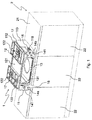
Fig. 1 is a perspective view of a household cooking appliance according to the invention, coupled to a top of a kitchen cabinet; -
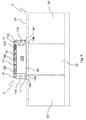
Fig. 2 is a front view of the household appliance ofFig. 1 , wherein the cooking top has a different configuration; -
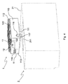
Figs. 3 and4 are front and rear views of the household appliance ofFig. 1 , separated from the top of the kitchen cabinet. - In this description, any reference to "an embodiment" will indicate that a particular configuration, structure or feature described in regard to the implementation of the invention is comprised in at least one embodiment. Therefore, the phrase "in an embodiment" and other similar phrases, which may be present in different parts of this description, will not necessarily be all related to the same embodiment. Furthermore, any particular configuration, structure or feature may be combined in one or more embodiments in any way deemed appropriate. The references below are therefore used only for simplicity's sake, and do not limit the protection scope or extension of the various embodiments.
- With reference to
Figs. 1-4 , ahousehold appliance 1 according to the invention is positioned on akitchen cabinet 2, preferably of the type for embedded household appliances; saidcabinet 2 comprises atop 21 supporting thehousehold appliance 1, anddoors 22 that can be used for hiding further household appliances, such as, for example, a dishwasher, a washing machine, a refrigerator, or the like. - The height of the
top 21 relative to the base of thecabinet 2 is preferably comprised between 61 and 100 cm, more preferably approx. 82 cm. - The top 21 may comprise an
aperture 211 that, as will be further explained in this description, allows thehousehold appliance 1 to be installed into thecabinet 2 in such a way as to improve the utilization of the space available in the premises. - The
household appliance 1 comprises the following parts: - a
hollow body 11 that comprises a base wall 111 (also referred to as bottom wall), atop wall 112, a pair of side walls 113,114 and aback wall 115, wherein said walls 111-115 define acavity 110 preferably accessible at the front through an aperture; - a
cooking top 12 positioned on thetop wall 112 of saidhollow body 11, wherein saidcooking top 12 comprises at least oneheating element 122; - supply means 15 configured for feeding said at least one heating means 122.
- The side walls 113,114 and the
back wall 115 preferably have a height that allows a user to load and unload pots on/from thecooking top 12 when thebase wall 111 of thehousehold appliance 1 is resting on a top of a cabinet, preferably for embedded household appliances, under which a second household appliance can be placed, e.g. a dishwasher, a refrigerator, a washing machine, or the like. - The
cooking top 12 comprises retention means (e.g. railings preferably having a maximum height of 5 cm) that can prevent pots positioned on thecooking top 12 from falling onto thetop 21. - It must be pointed out that the vertical development of the side walls 113-115, i.e. the height of the
household appliance 1, is preferably comprised between 15 and 30 cm, so that the cooking top will lie at a height between 76 and 130 cm, which is the optimal worktop height for people who are 138cm to 210cm tall, i.e. most adult people. - In the
cavity 110 one may preferably position anoven 13 or a coffee-making machine (not shown in the annexed drawings), or a combination of such household appliances. Thecooking top 12 may be of any type: gas (methane, propane or the like), electric (Joule effect and/or induction), or a combination of said one or more types. Theoven 13 may be of any type: microwave, gas, electric, steam, or a combination or one or more of such types (e.g. electric/microwave, gas/electric or other combinations). - The man skilled in the art may nevertheless use any other combination of cooking tops and ovens of any other type, without however departing from the teachings of the present invention.
- The
oven 13 comprises amuffle 131, inside of which food to be cooked can be placed; said muffle has, for example, a width of 50 cm, so that thewhole household appliance 1 will preferably have a total width of 70 cm. - According to a further alternative example, the muffle may have a width of 70 cm, so that the
whole household appliance 1 will preferably have a total width of 90 cm. Based on the type of cooking top in use, the supply means 15 may comprise a Venturi tube and/or a gas flow/concentration control valve and/or an electric regulator capable of varying the voltage and/or current and/or frequency and/or another property of an electric current and/or the like; said supply means are positioned upstream of said heating element and, for a gas cooking top, they perform the task of regulating the flow of fuel (e.g. methane, propane, butane) before said mixture is mixed with an oxidant (e.g. air) and burnt in the heating element (burner); instead, for an electric and/or induction cooking top, said supply means will vary some properties of an electric current (e.g. frequency, voltage, intensity), so that the heating element will output the correct thermal power. It must be pointed out that, in the electric case, the supply means may perform this thermal power regulation by interrupting the electric current by means of a switch (whether a manual or an automatic one), possibly taking also into account the temperature detected by a temperature sensor (e.g. a thermometer, a thermostat, an infrared sensor, or the like) positioned within or near the heating elements. These supply means are advantageously arranged along one or more side walls 113-115 and/or along thebottom wall 111, so that the thickness of thecooking top 12 will be reduced to advantage of the height of thecavity 110. - If the
cavity 110 houses anoven 13 and the supply means are arranged along thebottom wall 111, the bottom of themuffle 131 may be suitably dished to allow accommodating said supply means without increasing the dimensions of thehousehold appliance 1 on thetop 21, so as to better exploit the space available in the premises where saidhousehold appliance 1 is positioned. - For better ventilation (in the presence of the gas flow control valve) and/or cooling (in the presence of the electric regulator) of the supply means 15, one or more side walls 113-115 may comprise one or
more apertures 118, preferably in proximity to the supply means 15, saidapertures 118 being so shaped and sized as to allow air to flow through and, preferably, to prevent the user from coming into direct contact with said supply means 15. - The positioning of the
oven 13 inside thecavity 110 advantageously allows improving the utilization of the available space, because a fairly large oven can thus be arranged where it would otherwise be impossible to place an oven of any kind together with a cooking top positioned at a usable height. - The
household appliance 1 also comprises electric 116 and/or hydraulic 117 (for gas) supply fittings, which allow feeding thecooking top 12 and possibly also the oven 13 (with gas and/or electric current). - By combining an oven and a cooking top into a single household appliance it is possible to reduce the number of wires and/or gas pipes that need to be positioned in the premises, resulting in more space available therein. As can be seen in
Fig. 4 , by laying thecooking top 12 on anoven 13 having a reduced height it is advantageously possible to position thehydraulic supply fittings 117 on thebottom wall 111. - In this manner, said
hydraulic fittings 117 can also protrude downwards from thewall 111, using the room offered by theaperture 211 in thetop 21, so that gas pipes (not shown in the annexed drawings) can be positioned within thecabinet 2. - With the gas pipes so arranged, the
household appliance 1 and thecabinet 2 can be brought nearer to a wall of the premises where saidhousehold appliance 1 is to be positioned, so as to better exploit the available space than would be possible when using a gas cooking range according to the prior art; in fact, in such cooking ranges the gas pipes are arranged along the backside wall, because the bottom wall is usually too close to the floor or even directly laid thereon, and such an arrangement of the fittings reduces the room available for the oven and/or makes it impossible to draw said cooking range near to a wall. - Likewise, also the
electric supply fittings 116 can be positioned on thebottom wall 111, leading to the same advantages as described above. - As an alternative, the
fittings household appliance 1 in the premises where it is located. For example, this arrangement of the fittings allows installing the household appliance even in the absence of anaperture 211. - The
oven 13 comprises at least one heating element, e.g. a thermal resistor, which can advantageously be positioned as close as possible to the ceiling of the cooking chamber of the oven, i.e. as close as possible to thecooking top 12, thus increasing the usable space within the cooking chamber and improving the utilization of the space occupied by thehousehold appliance 1 in the premises where it is located. - In addition, the positioning of the heating element in proximity to the ceiling of the cooking chamber, i.e. of the
muffle 131, will produce no adverse effects on food cooking, since the reduced height of the side walls of theoven 13 will ensure that any food placed inside the cooking chamber will receive a sufficient amount of heat. Besides, the heating element thus arranged will also allow heating thecooking top 12, thereby reducing the quantity of energy consumed by the heating elements of thecooking top 12 for heating foods or pots placed thereon. - In particular, the
cooking top 12 may also comprise a cooking plate 121 (seeFig. 1 ). The cooking plate 121 (e.g. a broiler) comprises a heating element of its own, preferably an electric one, positioned under it and allowing food to be cooked without adding unsaturated fats. The arrangement of the heating element of theoven 13 underneath the broiler, also because of the reduced height of thecooking top 12, allows recovering part of the heat generated by the operation of the oven for cooking food placed on said broiler, thus reducing the energy consumption of thehousehold appliance 1. This means that the heating elements of the broiler can advantageously be less powerful than those of prior-art broilers, resulting in smaller dimensions and a larger volume of the cooking chamber - the volume of the household appliance being equal - thereby improving the utilization of the usable room in the premises where thehousehold appliance 1 is located. - In addition or as an alternative to the above, the heating element of the
oven 13 may also be positioned on the bottom of themuffle 131. - The
muffle 131 may also comprise a rotary plate (particularly useful when theoven 13 is a microwave oven) and/or ventilation means for improving air circulation within themuffle 131 during the food cooking process. - The
household appliance 1 may comprise adoor 16 configured for closing the aperture of themuffle 131 of theoven 13; saiddoor 16 may have either a vertical axis of rotation (as in the example shown in the annexed drawings) or a horizontal one. In this latter case, the space necessary for opening and closing the door (i.e. the envelope of the door) is smaller than the space necessary for opening and closing a door with a vertical axis, thus advantageously improving the utilization of the usable space in the premises where thehousehold appliance 1 is located. - The
oven 12 comprises also an insulating layer (e.g. made of rock wool or the like) to improve the thermal insulation of the cooking chamber. This insulating layer may have a thickness preferably comprised between 0.5 cm and 3 cm, since the reduced height of theoven 13 reduces the area of heat exchange with the outside environment, and therefore - the volume of the cooking chamber being equal - the dimensions of thewhole household appliance 1 can be reduced in order to improve the utilization of the usable space in the premises where thehousehold appliance 1 is located. - Also, the insulating layer may be totally absent under at least one portion of the
cooking top 12, thus further reducing the height of thecooking top 12 to advantage of the height of the cooking chamber of theoven 13. In addition to this, the removal of the insulating layer will increase the amount of heat yielded to thecooking top 12, thus improving the heating of pots and/or foods placed thereon. - In order to improve user safety, the
cooking top 12 may also comprise signalling means (not shown in the annexed drawings) configured for signalling to the user when thecooking top 12 has reached a certain temperature, preferably a temperature that might cause skin burns to the user in case of contact with saidcooking top 12. In fact, the reduction of the thickness of the insulating layer under thecooking top 12 or its (partial) removal will produce an increased temperature of saidcooking top 12 when theoven 13 is in operation. - These signalling means may comprise
grates 17 coated with a thermochromic material that changes color and/or opacity level and/or another optical property with temperature;such grates 17 can be positioned over thecooking top 12, so that pots can be laid thereon. - As an alternative to or in combination with the signalling means, it is also possible to use a cover so shaped as to shield at least a part of the
cooking top 12, preferably the hottest part thereof (e.g. the broiler), for improved user safety. - The
household appliance 1 also comprises one ormore control panels cooking top 12 and/or theoven 13, i.e. thehousehold appliance 1. Thesecontrol panels cavity 110 along one side of at least one of the side walls 113,114. In this manner, it is advantageously possible to increase the space available on thetop wall 112 for thecooking top 12, thereby improving the utilization of the usable space in the premises where thehousehold appliance 1 is located because - the dimensions of thecooking top 12 being equal - thehousehold appliance 1 can be smaller. - As an alternative to or in combination with such an arrangement of the
control panels control panels cooking top 12, so as to increase the volume in thecavity 110 and allow, for example, positioning anoven 13 having alarger muffle 131. - The
control panels household appliance 1. - If the cooking top comprises gas-
type heating elements 122, at least one of thecontrol panels knob 141 operating a valve capable of varying the gas flow towards theburner 122. It must be pointed out that in prior-art gas cooking ranges, the gas flow control valve is usually positioned underneath the cooking top, since the distance between said valve and the burner cannot be excessive (at most 10-15 cm) due to load losses. In thehousehold appliance 1 according to the invention, instead, thevalve 15 can be positioned along one of the side walls 113,114 and/or along thebottom wall 111, because the reduced height of thehousehold appliance 1 allows positioning the knobs and thevalves 15 in proximity to one of the side walls 113,114 and/or to thebottom wall 111, while also being close to thecooking top 12. In this manner, it is possible to reduce the thickness of thecooking top 12 to advantage of the height of theoven 13, thus better exploiting the available space in the premises where saidhousehold appliance 1 is located. - The top 21 of the
cabinet 2 may also comprise a horizontally-pivoted top (not shown in the annexed drawings), to which thebottom wall 111 of thehousehold appliance 1 is secured. Horizontal pivoting systems are normally employed in kitchens for small boats (which are more subject to oscillations caused by sea waves) in order to keep cooking tops and ranges levelled even when the boat is subject to rolling and/or pitching motions. By using a horizontally-pivoted top, it is possible to make most use of the space available in the premises where thehousehold appliance 1 has to be installed, since horizontally-pivoted cooking ranges according to the prior art need to have a greater vertical development than thehousehold appliance 1 according to the invention; this characteristic, in fact, makes it necessary to install said horizontally-pivoted ranges by means of rotary joints attached to the side walls of said ranges. This type of installation increases the volume occupied by the cooking range because the cabinet must be so configured as to form a pit or a recess where said cooking range can be accommodated, since such cooking ranges cannot be laid on a horizontally-pivoted top due the excessive height at which the cooking top would then be located. - Of course, the example described so far may be subject to many variations. For brevity, the following description will only highlight those parts which make this and the next variants different from the above-described main embodiment; for the same reason, wherever possible the same reference numerals, with the addition of one or more apostrophes, will be used for indicating structurally or functionally equivalent elements.
- A first variant of the invention comprises a household appliance similar to the
household appliance 1 just described, which comprises a coffee-making machine positioned in thecavity 110 in place of theoven 13. This variant offers the same advantages as the main variant, i.e. it provides better space utilization (one household appliance performing two tasks rather than just one) and higher energetic efficiency (a part of the heat produced for making coffee can be reused for preparing foods on the cooking top, and vice versa). - A second variant of the invention comprises a household appliance similar to those described for the preceding embodiments, wherein said household appliance comprises a coffee-making machine positioned in the
cavity 110 together with an oven similar to theoven 13. - In this variant of the household appliance, components can be shared between the coffee-making machine and the oven (e.g. a part of the heating element of the oven can also be used for heating the water used for making coffee), thus providing better space utilization and higher energetic efficiency of said household appliance.
- A third and last variant comprises a household appliance similar to those described for the preceding embodiments, wherein said household appliance comprises also a hood, preferably of the filtering type, positioned over the cooking top and secured, through support means (such as, for example, a hollow box-shaped housing or a panel), to the
top wall 112 and/or to one or more of the side walls 113-115, weighing upon them, so that the rigidity of said walls is exploited for bearing the weight of said hood. This improves the utilization of the space where the household appliance is located, because it is not necessary to use dedicated support means for supporting the hood. Furthermore, the hood is more effective than prior-art solutions, because said hood must be positioned at a shorter distance from thecooking top 12 due to the limited strength of the side walls 113-115, thus advantageously reducing the quantity of fumes and/or vapours not aspirated and/or treated by it. - The present description has tackled some of the possible variants, but it will be apparent to the man skilled in the art that other embodiments may also be implemented, wherein some elements may be replaced with other technically equivalent elements. The present invention is not therefore limited to the explanatory examples described herein, but may be subject to many modifications, improvements or replacements of equivalent parts and elements without departing from the basic inventive idea, as set out in the following claims.
Claims (15)
- Household cooking appliance (1), comprising- a hollow body (11) that comprises a bottom wall (111), a top wall (112), a pair of side walls (113,114) and a back wall (115), wherein said walls (111-115) define a cavity (110) accessible through an aperture,- a cooking top (12) positioned on the top wall (112) of said hollow body (11), wherein said cooking top (12) comprises at least one heating element (122),- supply means (15) configured for feeding said at least one heating means (122),characterized in that
said supply means (15) are positioned along one or more of the side walls (113-115) and/or along the bottom wall (111). - Household appliance (1) according to claim 1, wherein at least one of the side walls (113-115) comprises at least one aperture (118) allowing entry of air.
- Household appliance (1) according to claim 1 or 2, comprising supply fittings (116,117) positioned on the bottom wall (111).
- Household appliance (1) according to any one of claims 1 to 3, wherein the part lying under at least one portion of the cooking top (12) has no insulating layer.
- Household appliance (1) according to any one of claims 1 to 4, wherein the cooking top (12) comprises signalling means (17) configured for signalling when said cooking top has reached a certain temperature (12).
- Household appliance (1) according to claim 5, wherein the signalling means comprise grates (17) coated with a thermochromic material.
- Household appliance (1) according to any one of claims 1 to 6, comprising at least one control panel (14a,14b) that comprises at least one knob (141) and/or one push-button for controlling the supply means (15), and wherein said control panel (14a,14b) is arranged at the front near the side walls (113-114) or is positioned on the top wall (112).
- Household appliance (1) according to any one of claims 1 to 7, comprising an oven (13) positioned inside the cavity (110).
- Household appliance according to claim 8, comprising a coffee-making machine positioned in the cavity (110) together with the oven (13), wherein said oven (13) comprises a heating element, and wherein the coffee-making machine uses at least a part of said heating element for heating water.
- Household appliance (1) according to any one of claims 1 to 8, comprising a coffee-making machine positioned in the cavity (110).
- Household appliance according to any one of claims 1 to 10, comprising a hood positioned over said cooking top (12) and configured for weighing upon at least one of the side walls (113-115) .
- Household appliance (1) according to any one of the preceding claims, wherein the supply means comprise an air/gas mixer and/or a regulator valve (15), and wherein the heating element comprises a burner (122).
- Household appliance (1) according to any one of the preceding claims, wherein the supply means comprise an electric regulator, and wherein the heating element comprises an electric plate (121).
- Household appliance (1) according to any one of the preceding claims, wherein the cooking top (12) comprises retention means configured for preventing objects from falling from said cooking top (12).
- Cabinet (2) comprising a top (21) and a household appliance (1) according to any one of claims 1 to 14, wherein said top (21) comprises a horizontally-pivoted top, and wherein the bottom wall (111) of said household appliance (1) is secured on said horizontally-pivoted top.
Applications Claiming Priority (1)
| Application Number | Priority Date | Filing Date | Title |
|---|---|---|---|
| ITTO20140694 | 2014-09-04 |
Publications (1)
| Publication Number | Publication Date |
|---|---|
| EP2993407A1 true EP2993407A1 (en) | 2016-03-09 |
Family
ID=52000995
Family Applications (1)
| Application Number | Title | Priority Date | Filing Date |
|---|---|---|---|
| EP15183106.2A Withdrawn EP2993407A1 (en) | 2014-09-04 | 2015-08-31 | Household cooking appliance |
Country Status (1)
| Country | Link |
|---|---|
| EP (1) | EP2993407A1 (en) |
Cited By (3)
| Publication number | Priority date | Publication date | Assignee | Title |
|---|---|---|---|---|
| US20200363069A1 (en) * | 2019-05-13 | 2020-11-19 | Instant Brands Inc. | Control Panel and Electric Cooking Appliance |
| CN112393277A (en) * | 2020-10-13 | 2021-02-23 | 华帝股份有限公司 | Integrated cooker with refrigeration function and control method thereof |
| US20220099302A1 (en) * | 2020-09-28 | 2022-03-31 | Midea Group Co., Ltd. | Modulating oven burner control for gas cooking appliance |
Citations (6)
| Publication number | Priority date | Publication date | Assignee | Title |
|---|---|---|---|---|
| US3270183A (en) * | 1963-11-14 | 1966-08-30 | Gen Electric | Circuitry for electric oven |
| JP2001012742A (en) * | 1999-06-30 | 2001-01-19 | Harman Co Ltd | Gas cooker |
| US20030136395A1 (en) * | 2002-01-22 | 2003-07-24 | Alessandro Distaso | Gas burner valve assembly |
| JP2004060961A (en) * | 2002-07-26 | 2004-02-26 | Rinnai Corp | Gas range |
| JP2007298224A (en) * | 2006-04-28 | 2007-11-15 | Osaka Gas Co Ltd | Piping structure for built-in cooking stove, and built-in cooking stove |
| WO2011108016A1 (en) * | 2010-03-03 | 2011-09-09 | Sauro Bianchelli | Innovative domestic appliance with dual function |
-
2015
- 2015-08-31 EP EP15183106.2A patent/EP2993407A1/en not_active Withdrawn
Patent Citations (6)
| Publication number | Priority date | Publication date | Assignee | Title |
|---|---|---|---|---|
| US3270183A (en) * | 1963-11-14 | 1966-08-30 | Gen Electric | Circuitry for electric oven |
| JP2001012742A (en) * | 1999-06-30 | 2001-01-19 | Harman Co Ltd | Gas cooker |
| US20030136395A1 (en) * | 2002-01-22 | 2003-07-24 | Alessandro Distaso | Gas burner valve assembly |
| JP2004060961A (en) * | 2002-07-26 | 2004-02-26 | Rinnai Corp | Gas range |
| JP2007298224A (en) * | 2006-04-28 | 2007-11-15 | Osaka Gas Co Ltd | Piping structure for built-in cooking stove, and built-in cooking stove |
| WO2011108016A1 (en) * | 2010-03-03 | 2011-09-09 | Sauro Bianchelli | Innovative domestic appliance with dual function |
Cited By (5)
| Publication number | Priority date | Publication date | Assignee | Title |
|---|---|---|---|---|
| US20200363069A1 (en) * | 2019-05-13 | 2020-11-19 | Instant Brands Inc. | Control Panel and Electric Cooking Appliance |
| US12158272B2 (en) * | 2019-05-13 | 2024-12-03 | Ib Appliances Us Holdings Llc | Control panel and electric cooking appliance |
| US20220099302A1 (en) * | 2020-09-28 | 2022-03-31 | Midea Group Co., Ltd. | Modulating oven burner control for gas cooking appliance |
| US11754291B2 (en) * | 2020-09-28 | 2023-09-12 | Midea Group Co., Ltd. | Modulating oven burner control for gas cooking appliance |
| CN112393277A (en) * | 2020-10-13 | 2021-02-23 | 华帝股份有限公司 | Integrated cooker with refrigeration function and control method thereof |
Similar Documents
| Publication | Publication Date | Title |
|---|---|---|
| CA2508416C (en) | Gas range and method for using the same | |
| KR101531060B1 (en) | Oven range including air circulation means | |
| KR102297342B1 (en) | Heating device and cooking appliance | |
| US6729323B1 (en) | Air-inlet assembly for a gas cooking appliance | |
| AU2009282897B2 (en) | Hybrid broil system-electric broil element | |
| US10006639B2 (en) | Appliance side panel with air channel | |
| US2526476A (en) | Apartment range | |
| US20100282237A1 (en) | Front controls for gas cooking range | |
| JP6321467B2 (en) | Grill equipment | |
| KR200482959Y1 (en) | Open and wind-blocking appliance for cooking stove | |
| KR101358189B1 (en) | Hot water heater using waste heat of gas range | |
| WO2018219709A1 (en) | Cooker with vapor generator | |
| US20200217504A1 (en) | Method of operating an oven appliance based on fuel type | |
| EP3865042A1 (en) | Heat recovery oven with dishwasher | |
| KR20110063928A (en) | Cooker | |
| KR20220123973A (en) | cooking equipment | |
| CN104976670B (en) | A kind of embedded dual-purpose kitchen range | |
| CN203571812U (en) | Induction cooker | |
| KR100707426B1 (en) | Electric oven with vessel heating heater | |
| JP7780946B2 (en) | Cooking device, method and program for controlling cooking device | |
| KR102773562B1 (en) | remotely controllable induction compound cooking facility | |
| CN218178961U (en) | A kitchen integrated cooking appliance and its electrical cabinet | |
| AP470A (en) | Oven with electrical heating element. | |
| KR100985257B1 (en) | Heating cooker and its control method | |
| KR101531061B1 (en) | An oven range |
Legal Events
| Date | Code | Title | Description |
|---|---|---|---|
| PUAI | Public reference made under article 153(3) epc to a published international application that has entered the european phase |
Free format text: ORIGINAL CODE: 0009012 |
|
| AK | Designated contracting states |
Kind code of ref document: A1 Designated state(s): AL AT BE BG CH CY CZ DE DK EE ES FI FR GB GR HR HU IE IS IT LI LT LU LV MC MK MT NL NO PL PT RO RS SE SI SK SM TR |
|
| AX | Request for extension of the european patent |
Extension state: BA ME |
|
| 17P | Request for examination filed |
Effective date: 20160906 |
|
| RBV | Designated contracting states (corrected) |
Designated state(s): AL AT BE BG CH CY CZ DE DK EE ES FI FR GB GR HR HU IE IS IT LI LT LU LV MC MK MT NL NO PL PT RO RS SE SI SK SM TR |
|
| RAP1 | Party data changed (applicant data changed or rights of an application transferred) |
Owner name: WHIRLPOOL EMEA S.P.A |
|
| 17Q | First examination report despatched |
Effective date: 20170526 |
|
| STAA | Information on the status of an ep patent application or granted ep patent |
Free format text: STATUS: THE APPLICATION IS DEEMED TO BE WITHDRAWN |
|
| 18D | Application deemed to be withdrawn |
Effective date: 20171006 |