EP2993327A1 - Anomaly determination system and anomaly determination method - Google Patents
Anomaly determination system and anomaly determination method Download PDFInfo
- Publication number
- EP2993327A1 EP2993327A1 EP14819552.2A EP14819552A EP2993327A1 EP 2993327 A1 EP2993327 A1 EP 2993327A1 EP 14819552 A EP14819552 A EP 14819552A EP 2993327 A1 EP2993327 A1 EP 2993327A1
- Authority
- EP
- European Patent Office
- Prior art keywords
- pressure
- anomaly
- flow rate
- difference
- sensor
- Prior art date
- Legal status (The legal status is an assumption and is not a legal conclusion. Google has not performed a legal analysis and makes no representation as to the accuracy of the status listed.)
- Granted
Links
- 238000000034 method Methods 0.000 title claims description 39
- 239000012530 fluid Substances 0.000 claims abstract description 31
- 230000002547 anomalous effect Effects 0.000 claims description 36
- 230000008569 process Effects 0.000 description 21
- 238000002347 injection Methods 0.000 description 8
- 239000007924 injection Substances 0.000 description 8
- 238000011144 upstream manufacturing Methods 0.000 description 8
- 238000001816 cooling Methods 0.000 description 7
- 239000000446 fuel Substances 0.000 description 7
- 239000003054 catalyst Substances 0.000 description 6
- 239000007788 liquid Substances 0.000 description 4
- 238000005259 measurement Methods 0.000 description 4
- 239000003921 oil Substances 0.000 description 4
- 239000013618 particulate matter Substances 0.000 description 3
- 238000000746 purification Methods 0.000 description 3
- 239000000919 ceramic Substances 0.000 description 1
- 239000002826 coolant Substances 0.000 description 1
- 230000007423 decrease Effects 0.000 description 1
- 238000010586 diagram Methods 0.000 description 1
- 230000008717 functional decline Effects 0.000 description 1
- 239000002184 metal Substances 0.000 description 1
- 230000004048 modification Effects 0.000 description 1
- 238000012986 modification Methods 0.000 description 1
- 239000010705 motor oil Substances 0.000 description 1
- 230000003647 oxidation Effects 0.000 description 1
- 238000007254 oxidation reaction Methods 0.000 description 1
- 230000009467 reduction Effects 0.000 description 1
- 230000008929 regeneration Effects 0.000 description 1
- 238000011069 regeneration method Methods 0.000 description 1
Images


Classifications
-
- G—PHYSICS
- G01—MEASURING; TESTING
- G01L—MEASURING FORCE, STRESS, TORQUE, WORK, MECHANICAL POWER, MECHANICAL EFFICIENCY, OR FLUID PRESSURE
- G01L13/00—Devices or apparatus for measuring differences of two or more fluid pressure values
-
- F—MECHANICAL ENGINEERING; LIGHTING; HEATING; WEAPONS; BLASTING
- F02—COMBUSTION ENGINES; HOT-GAS OR COMBUSTION-PRODUCT ENGINE PLANTS
- F02D—CONTROLLING COMBUSTION ENGINES
- F02D41/00—Electrical control of supply of combustible mixture or its constituents
- F02D41/22—Safety or indicating devices for abnormal conditions
-
- F—MECHANICAL ENGINEERING; LIGHTING; HEATING; WEAPONS; BLASTING
- F02—COMBUSTION ENGINES; HOT-GAS OR COMBUSTION-PRODUCT ENGINE PLANTS
- F02B—INTERNAL-COMBUSTION PISTON ENGINES; COMBUSTION ENGINES IN GENERAL
- F02B29/00—Engines characterised by provision for charging or scavenging not provided for in groups F02B25/00, F02B27/00 or F02B33/00 - F02B39/00; Details thereof
- F02B29/04—Cooling of air intake supply
- F02B29/0493—Controlling the air charge temperature
-
- G—PHYSICS
- G01—MEASURING; TESTING
- G01M—TESTING STATIC OR DYNAMIC BALANCE OF MACHINES OR STRUCTURES; TESTING OF STRUCTURES OR APPARATUS, NOT OTHERWISE PROVIDED FOR
- G01M15/00—Testing of engines
- G01M15/14—Testing gas-turbine engines or jet-propulsion engines
-
- F—MECHANICAL ENGINEERING; LIGHTING; HEATING; WEAPONS; BLASTING
- F02—COMBUSTION ENGINES; HOT-GAS OR COMBUSTION-PRODUCT ENGINE PLANTS
- F02D—CONTROLLING COMBUSTION ENGINES
- F02D2200/00—Input parameters for engine control
- F02D2200/02—Input parameters for engine control the parameters being related to the engine
- F02D2200/04—Engine intake system parameters
- F02D2200/0406—Intake manifold pressure
-
- F—MECHANICAL ENGINEERING; LIGHTING; HEATING; WEAPONS; BLASTING
- F02—COMBUSTION ENGINES; HOT-GAS OR COMBUSTION-PRODUCT ENGINE PLANTS
- F02D—CONTROLLING COMBUSTION ENGINES
- F02D41/00—Electrical control of supply of combustible mixture or its constituents
- F02D41/02—Circuit arrangements for generating control signals
- F02D41/18—Circuit arrangements for generating control signals by measuring intake air flow
-
- Y—GENERAL TAGGING OF NEW TECHNOLOGICAL DEVELOPMENTS; GENERAL TAGGING OF CROSS-SECTIONAL TECHNOLOGIES SPANNING OVER SEVERAL SECTIONS OF THE IPC; TECHNICAL SUBJECTS COVERED BY FORMER USPC CROSS-REFERENCE ART COLLECTIONS [XRACs] AND DIGESTS
- Y02—TECHNOLOGIES OR APPLICATIONS FOR MITIGATION OR ADAPTATION AGAINST CLIMATE CHANGE
- Y02T—CLIMATE CHANGE MITIGATION TECHNOLOGIES RELATED TO TRANSPORTATION
- Y02T10/00—Road transport of goods or passengers
- Y02T10/10—Internal combustion engine [ICE] based vehicles
- Y02T10/12—Improving ICE efficiencies
-
- Y—GENERAL TAGGING OF NEW TECHNOLOGICAL DEVELOPMENTS; GENERAL TAGGING OF CROSS-SECTIONAL TECHNOLOGIES SPANNING OVER SEVERAL SECTIONS OF THE IPC; TECHNICAL SUBJECTS COVERED BY FORMER USPC CROSS-REFERENCE ART COLLECTIONS [XRACs] AND DIGESTS
- Y02—TECHNOLOGIES OR APPLICATIONS FOR MITIGATION OR ADAPTATION AGAINST CLIMATE CHANGE
- Y02T—CLIMATE CHANGE MITIGATION TECHNOLOGIES RELATED TO TRANSPORTATION
- Y02T10/00—Road transport of goods or passengers
- Y02T10/10—Internal combustion engine [ICE] based vehicles
- Y02T10/40—Engine management systems
Definitions
- the present invention relates to an anomaly determination system and an anomaly determination method, which determine an anomaly of a pressure loss portion arranged in a fluid passage of a vehicle.
- a pressure loss portion is arranged in an intake air passage or an exhaust gas passage of the engine, which is an example of a fluid passage.
- the pressure loss portion is arranged to cool intake air or purify exhaust gas while causing pressure loss by friction with fluid.
- An intercooler is one of such pressure loss portions and is arranged in a portion of the intake air passage that is located downstream of a supercharger, which supercharges intake air. The intercooler cools intake air of which the temperature has been increased by being pressurized.
- a device that estimates an anomaly of a turbocharger and an anomaly of an intercooler from their temperatures (for example, refer to Patent Document 1).
- a sensor of the device detects a discharged air temperature, which is the temperature of a portion that is located upstream of the intercooler and between the turbocharger and the intercooler, and a temperature of a portion that is located downstream of the intercooler.
- the device calculates cooling efficiency from these temperatures and compares the calculated cooling efficiency with a map showing the cooling efficiency of the intercooler in a normal state. When the cooling efficiency declines to a value less than the normal value, the device determines that the intercooler is anomalous.
- Patent Document 1 Japanese Laid-Open Patent Publication No. 2005-188479
- the aforementioned device estimates an anomaly of the intercooler on the assumption that all sensors are in normal states and does not anticipate a case in which an anomaly occurs in a sensor.
- the device may give an erroneous determination when an anomaly occurs in a sensor.
- Such a problem is not limited to the aforementioned device.
- a similar problem may also occur in a system having a pressure loss portion arranged in a fluid passage.
- An object of the present invention is to increase the reliability of an anomaly determination system and an anomaly determination method that determine an anomaly of a pressure loss portion.
- An anomaly determination system including an inlet pressure sensor, an outlet pressure sensor, an outside pressure sensor, and an anomaly determination section.
- the inlet pressure sensor detects an inlet pressure of a pressure loss portion that is arranged in a fluid passage of a vehicle and causes pressure loss of fluid.
- the outlet pressure sensor detects an outlet pressure of the pressure loss portion.
- the outside pressure sensor detects an outside pressure, which is a pressure outside the fluid passage.
- the anomaly determination section determines an anomaly of the pressure loss portion.
- the anomaly determination section is configured to store a first pressure loss range indicative of pressure loss of the pressure loss portion in an anomalous state, determine whether a flow rate in the fluid passage is greater than or equal to a minimum flow rate at which the anomaly in the pressure loss portion is detectable, and determine that the pressure loss portion is anomalous if the following two conditions are both met: a difference between the inlet pressure and the outlet pressure, a difference between the outlet pressure and the outside pressure, and a difference between the outside pressure and the inlet pressure which differences are detected when the flow rate is less than the minimum flow rate are all included in an allowable range; and a pressure difference between the inlet pressure and the outlet pressure when the flow rate is greater than or equal to the minimum flow rate is included in the first pressure loss range.
- the anomaly determination method includes detecting an inlet pressure of the pressure loss portion, an outlet pressure of the pressure loss portion, and an outside pressure, which is a pressure outside the fluid passage, determining whether a flow rate in the fluid passage is greater than or equal to a minimum flow rate at which the anomaly of the pressure loss portion is detectable, and determining that the pressure loss portion is anomalous if the following two conditions are both met: a difference between the inlet pressure and the outlet pressure, a difference between the outlet pressure and the atmospheric pressure, and a difference between the atmospheric pressure and the inlet pressure which differences are detected when the flow rate is less than the minimum flow rate are included in an allowable range; and a pressure difference between the inlet pressure and the outlet pressure when the flow rate is greater than or equal to the minimum flow rate is included in a first pressure loss range indicative of pressure loss in an anomalous state of the pressure loss
- an anomaly of the pressure loss portion is determined using the inlet and outlet pressures of the pressure loss portion and the outside pressure.
- the flow rate in the fluid passage is a low flow rate such that the flow rate is lower than the minimum flow rate
- the inlet pressure, the outlet pressure, and the outside pressure are substantially equal to one another.
- the flow rate is a high flow rate
- the pressure difference of the pressure loss portion is included in the first pressure loss range under a condition in which all the sensors are normal, the pressure loss portion is determined to be anomalous, and the anomaly is confirmed. This increases the reliability of the anomaly determination result in the pressure loss portion.
- the anomaly determination system is applied to the diesel engine of a vehicle provided with a supercharger.
- a cylinder head 12 of the engine 11 is coupled to an intake manifold 15, which communicates with the interior of cylinders 13, and an exhaust manifold 16.
- An exhaust gas recirculation (EGR) pipe 17 is coupled to the exhaust manifold 16, and some of the exhaust gas flows back to the intake manifold 15 through the EGR pipe 17.
- An EGR valve 18 is arranged in a portion of the EGR pipe 17 to adjust the amount of gas that flows back.
- An EGR cooler 19 is also arranged in the EGR pipe 17 to decrease the temperature of the exhaust gas that flows back.
- the turbine wheel of the turbine 22 is coupled to a compressor wheel via a rotor shaft (neither is shown).
- a compressor 23 is arranged in a portion of an intake air passage 25 that is located upstream of the intake manifold 15.
- An airflow meter 24 is also arranged in a portion of the intake air passage 25 that is located upstream of the compressor 23.
- the airflow meter 24 detects an intake air amount Ga, which is a mass flow rate.
- the intercooler 26 is, for example, an air-cooled cooling device and has a core for cooling intake air.
- the core has tubes, fins, and the like.
- the intake air passes through the tubes.
- the fins and the tubes are alternately stacked.
- the intercooler 26 cools intake air delivered from the compressor 23 to increase the density of the intake air. If any of the tubes are clogged, the cooling efficiency declines and pressure loss increases.
- An inlet pressure sensor 31 is arranged in a portion of the intake air passage 25 that is located upstream of the intercooler 26 and detects an inlet pressure P IN of the intercooler 26.
- An outlet pressure sensor 32 is arranged in a portion of the intake air passage 25 that is located downstream of the intercooler 26 and detects an outlet pressure P OUT of the intercooler 26.
- An atmospheric pressure sensor 33 is arranged at a location in the vehicle that enables the sensor to detect an atmospheric pressure Patm as an outside pressure.
- An anomaly determination system 10 is a system for determining the presence or absence of an anomaly in the intercooler 26 and sensors 31-33.
- the system includes the inlet pressure sensor 31, the outlet pressure sensor 32, the atmospheric pressure sensor 33, and an ECU 35, which functions as an anomaly determination device (an anomaly determination section).
- the ECU 35 includes a CPU, a RAM, a ROM, and the like.
- the ECU 35 receives a measurement signal of an intake air amount Ga from the airflow meter 24 and receives an accelerator position signal from an accelerator position sensor 34 to calculate a fuel injection amount.
- the ECU 35 further receives a measurement signal of the atmospheric pressure Patm from the atmospheric pressure sensor 33 as an outside pressure sensor.
- the ECU 35 receives a measurement signal of an inlet pressure P IN from the inlet pressure sensor 31 and receives a measurement signal of an outlet pressure P OUT from the outlet pressure sensor 32.
- a diesel particulate filter (DPF) 37 is arranged in a portion of the exhaust gas passage 20 that is located downstream of the turbine 22.
- the DPF 37 which is formed of ceramics and a metal porous body, captures particulate matter (PM), which is contained in exhaust gas.
- the captured particulate matter is combusted in various types of regeneration processes.
- the ECU 35 confirms an anomaly of the intercooler or an anomaly of any of the sensors, the occurrence of the anomaly is displayed on a display section 36, such as a display or an indicator provided in the vehicle, to inform the driver of the anomaly.
- a display section 36 such as a display or an indicator provided in the vehicle
- the anomaly determination process is performed when a start condition is met, for example, when the ignition switch is turned on.
- the ECU 35 when the anomaly determination process is started, the ECU 35 initializes various types of variables and various types of flags, which are temporarily stored in the RAM and the like and used in the anomaly determination (step S1). When the initialization is completed, the ECU 35 performs a primary anomaly determination (step S2). In the primary anomaly determination, the presence or absence of an anomaly is determined in the inlet pressure sensor 31, the outlet pressure sensor 32, and the atmospheric pressure sensor 33.
- the ECU 35 receives the inlet pressure P IN , the outlet pressure P OUT , and the atmospheric pressure Patm, which are output from the respective sensors 31-33 (step S11). The ECU 35 then determines whether the inlet pressure P IN , the outlet pressure P OUT , and the atmospheric pressure Patm are substantially equal to one another (step S12). In other words, since the compressor 23 is not driven in a state of no load at start of the engine, the inlet pressure P IN , the outlet pressure P OUT , and the atmospheric pressure Patm are supposed to be the same as one another if no anomaly is present in the sensors 31-33. However, in practice, fluctuation ranges exist due to various factors among the three detected values.
- the ECU 35 calculates the differences between any two pressures selected from the inlet pressure P IN , the outlet pressure P OUT , and the atmospheric pressure Patm and obtains the absolute values of the differences,
- the ECU 35 determines whether each of the absolute values is within a predetermined allowable width.
- the allowable width is fluctuation of the detected value in each of the sensors 31-33 in a normal state and defines an allowable range.
- step S12 determines that the absolute value of each difference is within the allowable width (YES at step S12)
- the ECU determines that each of the sensors 31-33 is normal in the primary anomaly determination (step S13).
- anomalous sensor identification is performed to identify a sensor in which an anomaly has occurred (step S14).
- the anomalous sensor identification will now be described with reference to Fig. 4 .
- the ECU 35 determines whether an excessively high value or an excessively low value is included in the detected values of the three sensors 31-33 as shown in a table T. In other words, when one of the three detected values is excessively high or low and the other two values are substantially the same, it is determined that an anomaly is occurring in the sensor that has output the excessively high or the excessively low value.
- the outlet pressure sensor 32 is determined to be anomalous when the outlet pressure P OUT is higher than the atmospheric pressure Patm and the inlet pressure P IN , the absolute values of the difference between the outlet pressure P out and the atmospheric pressure Patm and the difference between the outlet pressure P out and the inlet pressure P in exceed the allowable width, and the absolute value of the difference between the atmospheric pressure Patm and the inlet pressure P IN is within the allowable width.
- the detected value of the outlet pressure sensor 32 is excessively high and tends to be excessive.
- the outlet pressure sensor 32 is determined to be anomalous when the outlet pressure P OUT is lower than the atmospheric pressure Patm and the inlet pressure P IN , the absolute values of the difference between the outlet pressure P OUT and the atmospheric pressure Patm and the difference between the outlet pressure P OUT and the inlet pressure P IN exceed the allowable width, and the absolute value of the difference between the atmospheric pressure Patm and the inlet pressure P IN is within the allowable width.
- the detected value of the outlet pressure P OUT is excessively low and tends to be undervalued.
- the inlet pressure sensor 31 is determined to be anomalous.
- the atmospheric pressure Patm is excessively higher or lower than the inlet pressure P IN and the outlet pressure P OUT , the atmospheric pressure sensor 33 is determined to be anomalous. In a case other than these cases, it is determined that two or more of the sensors 31-33 are likely to be anomalous.
- the ECU 35 determines whether an anomaly is present (step S3).
- the ECU 35 informs the driver of the occurrence of an anomaly by using the display section 36 (step S6).
- step S6 When an anomaly of a sensor is confirmed in the primary anomaly determination, anomaly determination of the intercooler 26 cannot be performed. Thus, the anomaly determination is finished.
- step S4 the secondary anomaly determination is performed (step S4).
- the secondary anomaly determination is repeated unless a finishing condition of the anomaly determination is satisfied, or an anomaly determination is confirmed.
- the secondary anomaly determination is repeated at intervals of, for example, a few dozens of milliseconds to a few seconds.
- the ECU 35 receives the intake air amount Ga from the airflow meter 24 (step S21).
- the intake air amount Ga may be input on conditions that the variation of the engine speed is within a predetermined allowable width and the variation of the fuel injection amount is within a predetermined allowable width.
- the average of the intake air amount Ga within a predetermined period of time may be calculated.
- the ECU 35 determines whether the intake air amount Ga is less than or equal to a reference mass flow rate Gth, which is used as a guide of a low flow rate condition (step S22).
- the reference mass flow rate Gth is the minimum intake air amount which is sufficient to detect clogging based on pressure loss of the intercooler 26.
- An example of the case in which the intake air amount Ga is less than or equal to the reference mass flow rate Gth is when fuel is not injected on start of the engine, or when no load is placed upon stopping of the vehicle.
- step S22 When it is determined that the intake air amount Ga is less than or equal to the reference mass flow rate Gth (YES at step S22) on start of the engine, in a similar way to step S11 to step S12, the inlet pressure P IN , the outlet pressure P OUT , and the atmospheric pressure Patm are input (step S23), and it is determined whether those values are substantially the same as one another (step S24).
- the inlet pressure P IN , the outlet pressure P OUT , and the atmospheric pressure Patm are the same as one another in a normal state (YES at step S24).
- the ECU 35 determines whether an intercooler anomaly flag F1 is ON (step S25).
- the intercooler anomaly flag F1 is indicative of whether an anomaly is detected in pressure loss of the intercooler 26 on a high flow rate condition. When an anomaly is present in the pressure loss, the flag is set at ON. In the absence of an anomaly, the flag is set at OFF.
- the intercooler anomaly flag F1 is in an initialized state (NO at step S25). This indicates that all the sensors 31-33 and the intercooler 26 are normal, and the current secondary anomaly determination is finished.
- the ECU 35 determines whether an anomaly is determined in the secondary anomaly determination (step S5). When the absence of an anomaly is determined (NO at step S5), the secondary anomaly determination is repeated (step 4).
- step S30 the secondary anomaly determination is performed on the high flow rate condition.
- the ECU 35 receives the intake air amount Ga (step S31), as well as the inlet pressure P IN and the outlet pressure P OUT (step S32).
- the ECU 35 calculates the pressure difference ⁇ P by subtracting the outlet pressure P OUT from the inlet pressure P IN (step S33).
- the ECU 35 reads out an anomaly determination map 40 from the ROM or the like (step S34).
- the horizontal axis indicates the square value of the intake air amount Ga, which is a mass flow rate
- the vertical axis indicates the pressure difference ⁇ P, which is calculated at step S33.
- the straight line in which the pressure difference ⁇ P increases proportional to the square value of the intake air amount Ga has a normal pressure loss gradient L1 indicative of the pressure loss of the normal intercooler 26.
- the normal area Z is an area including a margin of variation relative to the normal pressure loss gradient L1.
- a sensor anomaly area Z2 is an area in which the pressure difference ⁇ P is less than that of the normal area Z1. This area includes a state in which the inlet pressure sensor 31 is anomalous and its detected value is excessively low, and a state in which the outlet pressure sensor 32 is anomalous and its detected value is excessively high.
- the pressure difference ⁇ P is higher than that of the normal area Z1 in a range in which the intake air amount Ga is greater than or equal to the reference mass flow rate Gth.
- the start point of the intake air amount in the intercooler anomaly area Z3 is the aforementioned reference mass flow rate Gth.
- a sensor anomaly area Z4 is an area in which the mass flow rate (the intake air amount Ga) is lower than the reference mass flow rate Gth and the pressure difference ⁇ P is higher than that of the normal area Z1.
- the sensor anomaly area Z4 is an area in which the mass flow rate (intake air amount Ga) is greater than or equal to the reference mass flow rate Gth and the pressure difference ⁇ P is higher than that of the intercooler anomaly area Z3.
- This area includes a state in which the inlet pressure sensor 31 is anomalous and its detected value is excessively high, and a state in which the outlet pressure sensor 32 is anomalous and its detected value is excessively low.
- the ECU 35 determines whether the pressure difference ⁇ P is included in the normal area Z1 based on the received intake air amount Ga and the pressure difference ⁇ P by using the anomaly determination map 40 (step S35).
- the ECU 35 determines whether the sensor anomaly flag F2 is in an ON state (step S36).
- the sensor anomaly flag F2 is indicative of whether a sensor anomaly is detected on the low flow rate condition. In the presence of a sensor anomaly, the sensor anomaly flag F2 is set at ON. In the absence of a sensor anomaly, the sensor anomaly flag F2 is set at OFF.
- step S36 When the ECU 35 determines at step S36 that the sensor anomaly flag F2 is OFF (NO at step S36), all the sensors 31-33 and the intercooler 26 are normal, and this round of the secondary anomaly determination is finished. The procedure moves to step S5.
- step S36 determines that the sensor anomaly flag F2 is ON (YES at step S36)
- the sensor is anomalous and the pressure difference ⁇ P is included in the normal area Z1.
- the ECU 35 determines that the inlet pressure sensor 31 and the outlet pressure sensor 32 are not anomalous and determines that the atmospheric pressure sensor 33 is anomalous (step S37).
- step S5 determines at step S5 the presence of an anomaly (YES at step S5) and informs the driver of occurrence of an anomaly in the atmospheric pressure sensor 33 (step S6).
- step S35 When it is determined at step S35 that the pressure difference ⁇ P is not included in the normal area Z1 (NO at step S35), the ECU 35 determines whether the pressure difference ⁇ P is included in the intercooler anomaly area Z3 (step S38). When determining that the pressure difference ⁇ P is included in the intercooler anomaly area Z3 (YES at step S38), the ECU 35 determines whether the sensor anomaly flag F2 is ON (step S39).
- step S39 When it is determined that the sensor anomaly flag F2 is set at OFF (NO at step S39), each of the sensors 31-33 is normal on the low flow rate condition, and the pressure loss in the intercooler 26 is included in the intercooler anomaly area Z3. Thus, since the pressure loss is correctly measured and an anomaly is detected, the presence of the anomaly in the intercooler 26 is confirmed (step S40). The procedure then moves to step S5. When it is determined that the sensor anomaly flag F2 is set at ON (YES at step S39) at step S39, a sensor anomaly may be present. Thus, the procedure returns to step S5 without confirming the intercooler anomaly, and the secondary anomaly determination is repeated.
- the ECU 35 determines that an anomaly is present at step S5 (YES at step S5) and informs the driver of the anomaly using the display section 36 (step S6).
- step S24 After start of the engine, if an anomaly occurs in the inlet pressure sensor 31 or the outlet pressure sensor 32, it is determined at step S24 that the inlet pressure P IN , the outlet pressure P OUT , the atmospheric pressure Patm are not the same as one another (NO at step S24). At this time, the ECU 35 sets the sensor anomaly flag F2 at ON (step S27).
- the pressure difference ⁇ P is not included in the normal area Z1 and the intercooler anomaly area Z3, but it is included in the sensor anomaly areas Z2 or Z4 (NO at step S35 and NO at step S38).
- the ECU 35 determines whether the sensor anomaly flag F2 is ON (step 41). In a case in which the sensor anomaly flag F2 has already been set at ON in the process on the low flow rate condition (YES at step S41), the anomalous sensor is identified in similar way to the primary anomaly determination at step S14 (step S42).
- step S41 In a case in which the sensor anomaly flag F2 is OFF (NO at step S41), the procedure moves to step S5, and the secondary anomaly determination is repeated. After the sensor anomaly flag F2 on the low flow rate condition is set at ON, an anomaly is confirmed in the inlet pressure sensor 31 and the outlet pressure sensor 32.
- step S5 when an anomaly is confirmed in the inlet pressure sensor 31 or the outlet pressure sensor 32, the procedure moves to step S5, and the driver is informed of the sensor anomaly and the identified sensor (step S6).
- step S6 When a sensor anomaly is detected on the low flow rate condition and a sensor anomaly is detected on the high flow rate condition, the sensor anomaly is confirmed. This increases the reliability of an anomaly determination result in the sensor anomaly.
- the anomaly determination system may use the table T as shown in Fig. 8 or a map in the anomaly determination process.
- the table T or the map associates the intake air amount Ga, the pressure loss of the intercooler 26, and the pressure values of the sensors 31-33 with an anomaly occurrence location.
- the anomaly determination system receives the intake air amount Ga, the pressure loss, and the pressure values of the sensors 31-33 at moment to moment. These values may be compared to the table T and the like so that the presence or absence of an anomaly and an anomaly occurrence location are determined.
- the condition may be changed according to a fuel injection amount. For example, when the fuel injection amount is greater than or equal to a reference injection amount, determination is performed based on pressure loss of the intercooler 26. When the fuel injection amount is less than the reference injection amount, it is determined whether the inlet pressure P IN , the outlet pressure P OUT , and the atmospheric pressure Patm are equal to one another.
- the anomaly determination process is configured not to move to the secondary anomaly determination when an anomaly is determined on the primary determination.
- the secondary anomaly determination may be performed in such a case.
- the ECU 35 is configured to have a function of calculating the fuel injection amount Qfin. However, the ECU 35 may function only as an anomaly determination section.
- an anomaly of the intercooler 26 and anomalies of the sensors 31-33 are determined. However, if at least an anomaly of the intercooler 26 is detectable, other determination may be omitted. Alternatively, it may be determined that an anomaly has occurred in any of the sensors 31-33 without identifying the anomalous sensor.
- the configuration of the engine 11 provided with the anomaly determination system 10 is not limited to a diesel engine.
- the engine 11 may be a gasoline engine.
- the engine may be an engine without an EGR system.
- the pressure loss portion may be a pressure loss portion other than the intercooler, which is arranged in a fluid passage of a vehicle.
- the pressure loss portion may be an EGR cooler 19.
- the anomaly determination system has pressure sensors arranged upstream and downstream of the EGR cooler 19 in the EGR pipe 17.
- the pressure loss portion may be the DPF 37 or exhaust gas purification catalyst, which is arranged upstream of the DPF 37.
- the exhaust gas purification catalyst are an oxidation catalyst (not shown) and a selective reduction catalyst.
- the anomaly determination system 10 has pressure sensors, which are arranged upstream and downstream of the catalyst, which is subject to anomaly determination in the exhaust gas passage 20.
- the fluid may be liquid.
- the fluid may be engine oil.
- the pressure loss portion may be an oil filter or an oil cooler, which is arranged in an oil circuit.
- the fluid may be coolant.
- the pressure loss portion may be a radiator.
- the "outside pressure" refers to the pressure of liquid outside the fluid passage, for example, the pressure of liquid in a tank or an oil pan.
Landscapes
- Engineering & Computer Science (AREA)
- Chemical & Material Sciences (AREA)
- Combustion & Propulsion (AREA)
- Physics & Mathematics (AREA)
- Mechanical Engineering (AREA)
- General Engineering & Computer Science (AREA)
- General Physics & Mathematics (AREA)
- Thermal Sciences (AREA)
- Combined Controls Of Internal Combustion Engines (AREA)
- Valves And Accessory Devices For Braking Systems (AREA)
Abstract
Description
- The present invention relates to an anomaly determination system and an anomaly determination method, which determine an anomaly of a pressure loss portion arranged in a fluid passage of a vehicle.
- A pressure loss portion is arranged in an intake air passage or an exhaust gas passage of the engine, which is an example of a fluid passage. The pressure loss portion is arranged to cool intake air or purify exhaust gas while causing pressure loss by friction with fluid. An intercooler is one of such pressure loss portions and is arranged in a portion of the intake air passage that is located downstream of a supercharger, which supercharges intake air. The intercooler cools intake air of which the temperature has been increased by being pressurized.
- If an anomaly such as clogging occurs in the pressure loss portion, the original function declines. Thus, devices and methods that detect an anomaly of the pressure loss portion have been proposed. As an example, a device is proposed that estimates an anomaly of a turbocharger and an anomaly of an intercooler from their temperatures (for example, refer to Patent Document 1). A sensor of the device detects a discharged air temperature, which is the temperature of a portion that is located upstream of the intercooler and between the turbocharger and the intercooler, and a temperature of a portion that is located downstream of the intercooler. Furthermore, the device calculates cooling efficiency from these temperatures and compares the calculated cooling efficiency with a map showing the cooling efficiency of the intercooler in a normal state. When the cooling efficiency declines to a value less than the normal value, the device determines that the intercooler is anomalous.
- Patent Document 1: Japanese Laid-Open Patent Publication No.
2005-188479 - However, the aforementioned device estimates an anomaly of the intercooler on the assumption that all sensors are in normal states and does not anticipate a case in which an anomaly occurs in a sensor. Thus, the device may give an erroneous determination when an anomaly occurs in a sensor. Such a problem is not limited to the aforementioned device. A similar problem may also occur in a system having a pressure loss portion arranged in a fluid passage.
- An object of the present invention is to increase the reliability of an anomaly determination system and an anomaly determination method that determine an anomaly of a pressure loss portion.
- One aspect of the present disclosure is an anomaly determination system including an inlet pressure sensor, an outlet pressure sensor, an outside pressure sensor, and an anomaly determination section. The inlet pressure sensor detects an inlet pressure of a pressure loss portion that is arranged in a fluid passage of a vehicle and causes pressure loss of fluid. The outlet pressure sensor detects an outlet pressure of the pressure loss portion. The outside pressure sensor detects an outside pressure, which is a pressure outside the fluid passage. The anomaly determination section determines an anomaly of the pressure loss portion. The anomaly determination section is configured to store a first pressure loss range indicative of pressure loss of the pressure loss portion in an anomalous state, determine whether a flow rate in the fluid passage is greater than or equal to a minimum flow rate at which the anomaly in the pressure loss portion is detectable, and determine that the pressure loss portion is anomalous if the following two conditions are both met: a difference between the inlet pressure and the outlet pressure, a difference between the outlet pressure and the outside pressure, and a difference between the outside pressure and the inlet pressure which differences are detected when the flow rate is less than the minimum flow rate are all included in an allowable range; and a pressure difference between the inlet pressure and the outlet pressure when the flow rate is greater than or equal to the minimum flow rate is included in the first pressure loss range.
- Another aspect of the present invention is an anomaly determination method for determining an anomaly of a pressure loss portion, which is arranged in a fluid passage of a vehicle and causes pressure loss of fluid. The anomaly determination method includes detecting an inlet pressure of the pressure loss portion, an outlet pressure of the pressure loss portion, and an outside pressure, which is a pressure outside the fluid passage, determining whether a flow rate in the fluid passage is greater than or equal to a minimum flow rate at which the anomaly of the pressure loss portion is detectable, and determining that the pressure loss portion is anomalous if the following two conditions are both met: a difference between the inlet pressure and the outlet pressure, a difference between the outlet pressure and the atmospheric pressure, and a difference between the atmospheric pressure and the inlet pressure which differences are detected when the flow rate is less than the minimum flow rate are included in an allowable range; and a pressure difference between the inlet pressure and the outlet pressure when the flow rate is greater than or equal to the minimum flow rate is included in a first pressure loss range indicative of pressure loss in an anomalous state of the pressure loss portion.
- According to the above aspects, an anomaly of the pressure loss portion is determined using the inlet and outlet pressures of the pressure loss portion and the outside pressure. When the flow rate in the fluid passage is a low flow rate such that the flow rate is lower than the minimum flow rate, the inlet pressure, the outlet pressure, and the outside pressure are substantially equal to one another. Thus, it is possible to determine whether all the sensors are normal based on pressure differences among the inlet pressure, the outlet pressure, and the outside pressure. When the flow rate is a high flow rate, if the pressure difference of the pressure loss portion is included in the first pressure loss range under a condition in which all the sensors are normal, the pressure loss portion is determined to be anomalous, and the anomaly is confirmed. This increases the reliability of the anomaly determination result in the pressure loss portion.
-
-
Fig. 1 is a schematic diagram of an anomaly determination system according to one embodiment; -
Fig. 2 is a flowchart of an anomaly determination process executed in the anomaly determination system ofFig. 1 ; -
Fig. 3 is a flowchart of a primary anomaly determination, which is included in the anomaly determination process ofFig. 2 . -
Fig. 4 is a table showing the relationship between anomalous parts and their pressures, which is used in the anomaly determination process ofFig. 2 ; -
Fig. 5 is an anomaly determination map used in the anomaly determination process ofFig. 2 ; -
Fig. 6 is a flowchart of a secondary anomaly determination included in the anomaly determination process ofFig. 2 ; -
Fig. 7 is a flowchart of the secondary anomaly determination on a high flow rate condition in the secondary anomaly determination ofFig. 6 , and included in the anomaly determination process ofFig. 2 ; and -
Fig. 8 is a table used in an anomaly determination process in a modification. - An anomaly determination system and an anomaly determination method according to one embodiment will now be described. In the present embodiment, the anomaly determination system is applied to the diesel engine of a vehicle provided with a supercharger.
- As shown in
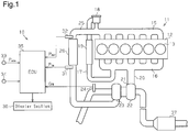
Fig. 1 , acylinder head 12 of theengine 11 is coupled to anintake manifold 15, which communicates with the interior ofcylinders 13, and anexhaust manifold 16. An exhaust gas recirculation (EGR)pipe 17 is coupled to theexhaust manifold 16, and some of the exhaust gas flows back to theintake manifold 15 through theEGR pipe 17. AnEGR valve 18 is arranged in a portion of theEGR pipe 17 to adjust the amount of gas that flows back. An EGRcooler 19 is also arranged in the EGRpipe 17 to decrease the temperature of the exhaust gas that flows back. - An
exhaust gas passage 20, which is located downstream of theexhaust manifold 16, is coupled to aturbine 22 of a turbocharger 21. The turbine wheel of theturbine 22 is coupled to a compressor wheel via a rotor shaft (neither is shown). - A
compressor 23 is arranged in a portion of anintake air passage 25 that is located upstream of theintake manifold 15. Anairflow meter 24 is also arranged in a portion of theintake air passage 25 that is located upstream of thecompressor 23. Theairflow meter 24 detects an intake air amount Ga, which is a mass flow rate. - An
intercooler 26, which is a pressure loss portion, is arranged in a portion of theintake air passage 25 that is located downstream of thecompressor 23. Theintercooler 26 is, for example, an air-cooled cooling device and has a core for cooling intake air. The core has tubes, fins, and the like. The intake air passes through the tubes. The fins and the tubes are alternately stacked. Theintercooler 26 cools intake air delivered from thecompressor 23 to increase the density of the intake air. If any of the tubes are clogged, the cooling efficiency declines and pressure loss increases. - An
inlet pressure sensor 31 is arranged in a portion of theintake air passage 25 that is located upstream of theintercooler 26 and detects an inlet pressure PIN of theintercooler 26. Anoutlet pressure sensor 32 is arranged in a portion of theintake air passage 25 that is located downstream of theintercooler 26 and detects an outlet pressure POUT of theintercooler 26. Anatmospheric pressure sensor 33 is arranged at a location in the vehicle that enables the sensor to detect an atmospheric pressure Patm as an outside pressure. - An
anomaly determination system 10 is a system for determining the presence or absence of an anomaly in theintercooler 26 and sensors 31-33. The system includes theinlet pressure sensor 31, theoutlet pressure sensor 32, theatmospheric pressure sensor 33, and anECU 35, which functions as an anomaly determination device (an anomaly determination section). TheECU 35 includes a CPU, a RAM, a ROM, and the like. TheECU 35 receives a measurement signal of an intake air amount Ga from theairflow meter 24 and receives an accelerator position signal from anaccelerator position sensor 34 to calculate a fuel injection amount. - The
ECU 35 further receives a measurement signal of the atmospheric pressure Patm from theatmospheric pressure sensor 33 as an outside pressure sensor. TheECU 35 receives a measurement signal of an inlet pressure PIN from theinlet pressure sensor 31 and receives a measurement signal of an outlet pressure POUT from theoutlet pressure sensor 32. - A diesel particulate filter (DPF) 37 is arranged in a portion of the
exhaust gas passage 20 that is located downstream of theturbine 22. The DPF 37, which is formed of ceramics and a metal porous body, captures particulate matter (PM), which is contained in exhaust gas. The captured particulate matter is combusted in various types of regeneration processes. - When the
ECU 35 confirms an anomaly of the intercooler or an anomaly of any of the sensors, the occurrence of the anomaly is displayed on adisplay section 36, such as a display or an indicator provided in the vehicle, to inform the driver of the anomaly. - Operation of the
anomaly determination system 10 will now be described. The anomaly determination process is performed when a start condition is met, for example, when the ignition switch is turned on. - As shown in
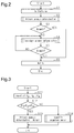
Fig. 2 , when the anomaly determination process is started, theECU 35 initializes various types of variables and various types of flags, which are temporarily stored in the RAM and the like and used in the anomaly determination (step S1). When the initialization is completed, theECU 35 performs a primary anomaly determination (step S2). In the primary anomaly determination, the presence or absence of an anomaly is determined in theinlet pressure sensor 31, theoutlet pressure sensor 32, and theatmospheric pressure sensor 33. - The primary anomaly determination will now be described with reference to
Fig. 3 . TheECU 35 receives the inlet pressure PIN, the outlet pressure POUT, and the atmospheric pressure Patm, which are output from the respective sensors 31-33 (step S11). TheECU 35 then determines whether the inlet pressure PIN, the outlet pressure POUT, and the atmospheric pressure Patm are substantially equal to one another (step S12). In other words, since thecompressor 23 is not driven in a state of no load at start of the engine, the inlet pressure PIN, the outlet pressure POUT, and the atmospheric pressure Patm are supposed to be the same as one another if no anomaly is present in the sensors 31-33. However, in practice, fluctuation ranges exist due to various factors among the three detected values. Thus, theECU 35 calculates the differences between any two pressures selected from the inlet pressure PIN, the outlet pressure POUT, and the atmospheric pressure Patm and obtains the absolute values of the differences, |PIN - POUT|, |POUT - Patm|, and |PIN - Patm|. TheECU 35 then determines whether each of the absolute values is within a predetermined allowable width. The allowable width is fluctuation of the detected value in each of the sensors 31-33 in a normal state and defines an allowable range. - When the
ECU 35 determines at step S12 that the absolute value of each difference is within the allowable width (YES at step S12), the ECU determines that each of the sensors 31-33 is normal in the primary anomaly determination (step S13). - When the
ECU 35 determines that the absolute value of each difference exceeds the allowable width, that is, the inlet pressure PIN, the outlet pressure POUT, and the atmospheric pressure Patm are not substantially the same as one another (NO at step S12), anomalous sensor identification is performed to identify a sensor in which an anomaly has occurred (step S14). - The anomalous sensor identification will now be described with reference to
Fig. 4 . TheECU 35 determines whether an excessively high value or an excessively low value is included in the detected values of the three sensors 31-33 as shown in a table T. In other words, when one of the three detected values is excessively high or low and the other two values are substantially the same, it is determined that an anomaly is occurring in the sensor that has output the excessively high or the excessively low value. - For example, the
outlet pressure sensor 32 is determined to be anomalous when the outlet pressure POUT is higher than the atmospheric pressure Patm and the inlet pressure PIN, the absolute values of the difference between the outlet pressure Pout and the atmospheric pressure Patm and the difference between the outlet pressure Pout and the inlet pressure Pin exceed the allowable width, and the absolute value of the difference between the atmospheric pressure Patm and the inlet pressure PIN is within the allowable width. In this case, the detected value of theoutlet pressure sensor 32 is excessively high and tends to be excessive. In contrast, theoutlet pressure sensor 32 is determined to be anomalous when the outlet pressure POUT is lower than the atmospheric pressure Patm and the inlet pressure PIN, the absolute values of the difference between the outlet pressure POUT and the atmospheric pressure Patm and the difference between the outlet pressure POUT and the inlet pressure PIN exceed the allowable width, and the absolute value of the difference between the atmospheric pressure Patm and the inlet pressure PIN is within the allowable width. In this case, the detected value of the outlet pressure POUT is excessively low and tends to be undervalued. - Similarly, when the inlet pressure PIN is excessively higher or lower than the outlet pressure POUT and the atmospheric pressure Patm, the
inlet pressure sensor 31 is determined to be anomalous. When the atmospheric pressure Patm is excessively higher or lower than the inlet pressure PIN and the outlet pressure POUT, theatmospheric pressure sensor 33 is determined to be anomalous. In a case other than these cases, it is determined that two or more of the sensors 31-33 are likely to be anomalous. - As shown in
Fig. 2 , when the normal determination and the anomalous sensor identification are finished in the primary anomaly determination, theECU 35 determines whether an anomaly is present (step S3). When the presence of an anomaly is determined (YES at step S3), theECU 35 informs the driver of the occurrence of an anomaly by using the display section 36 (step S6). When an anomaly of a sensor is confirmed in the primary anomaly determination, anomaly determination of theintercooler 26 cannot be performed. Thus, the anomaly determination is finished. When the absence of an anomaly is determined (NO at step S3), the secondary anomaly determination is performed (step S4). The secondary anomaly determination is repeated unless a finishing condition of the anomaly determination is satisfied, or an anomaly determination is confirmed. The secondary anomaly determination is repeated at intervals of, for example, a few dozens of milliseconds to a few seconds. - The procedure of the secondary anomaly determination will now be described with reference to
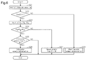
Fig. 6 . First, theECU 35 receives the intake air amount Ga from the airflow meter 24 (step S21). In consideration of fluctuation in the intake air amount Ga, the intake air amount Ga may be input on conditions that the variation of the engine speed is within a predetermined allowable width and the variation of the fuel injection amount is within a predetermined allowable width. Furthermore, the average of the intake air amount Ga within a predetermined period of time may be calculated. - The
ECU 35 determines whether the intake air amount Ga is less than or equal to a reference mass flow rate Gth, which is used as a guide of a low flow rate condition (step S22). The reference mass flow rate Gth is the minimum intake air amount which is sufficient to detect clogging based on pressure loss of theintercooler 26. An example of the case in which the intake air amount Ga is less than or equal to the reference mass flow rate Gth is when fuel is not injected on start of the engine, or when no load is placed upon stopping of the vehicle. - When it is determined that the intake air amount Ga is less than or equal to the reference mass flow rate Gth (YES at step S22) on start of the engine, in a similar way to step S11 to step S12, the inlet pressure PIN, the outlet pressure POUT, and the atmospheric pressure Patm are input (step S23), and it is determined whether those values are substantially the same as one another (step S24).
- Immediately after the process moves from the primary anomaly determination to the secondary anomaly determination, the inlet pressure PIN, the outlet pressure POUT, and the atmospheric pressure Patm are the same as one another in a normal state (YES at step S24). The
ECU 35 determines whether an intercooler anomaly flag F1 is ON (step S25). The intercooler anomaly flag F1 is indicative of whether an anomaly is detected in pressure loss of theintercooler 26 on a high flow rate condition. When an anomaly is present in the pressure loss, the flag is set at ON. In the absence of an anomaly, the flag is set at OFF. Immediately after the procedure moves from the primary anomaly determination to the secondary anomaly determination, the intercooler anomaly flag F1 is in an initialized state (NO at step S25). This indicates that all the sensors 31-33 and theintercooler 26 are normal, and the current secondary anomaly determination is finished. - As shown in
Fig. 2 , when finishing the first round of the secondary anomaly determination, theECU 35 determines whether an anomaly is determined in the secondary anomaly determination (step S5). When the absence of an anomaly is determined (NO at step S5), the secondary anomaly determination is repeated (step 4). - As shown in
Fig. 6 , when the intake air amount Ga exceeds the reference mass flow rate Gth during execution of the secondary anomaly determination (NO at step S22), the procedure moves to step S30. At step S30, the secondary anomaly determination is performed on the high flow rate condition. - The secondary anomaly determination on the high flow rate condition will now be described with reference to
Fig. 7 . TheECU 35 receives the intake air amount Ga (step S31), as well as the inlet pressure PIN and the outlet pressure POUT (step S32). TheECU 35 calculates the pressure difference ΔP by subtracting the outlet pressure POUT from the inlet pressure PIN (step S33). TheECU 35 reads out ananomaly determination map 40 from the ROM or the like (step S34). - In the
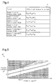
anomaly determination map 40 shown inFig. 5 , the horizontal axis indicates the square value of the intake air amount Ga, which is a mass flow rate, and the vertical axis indicates the pressure difference ΔP, which is calculated at step S33. In theanomaly determination map 40, the straight line in which the pressure difference ΔP increases proportional to the square value of the intake air amount Ga has a normal pressure loss gradient L1 indicative of the pressure loss of thenormal intercooler 26. The normal area Z is an area including a margin of variation relative to the normal pressure loss gradient L1. - A sensor anomaly area Z2 is an area in which the pressure difference ΔP is less than that of the normal area Z1. This area includes a state in which the
inlet pressure sensor 31 is anomalous and its detected value is excessively low, and a state in which theoutlet pressure sensor 32 is anomalous and its detected value is excessively high. In an intercooler anomaly area Z3, the pressure difference ΔP is higher than that of the normal area Z1 in a range in which the intake air amount Ga is greater than or equal to the reference mass flow rate Gth. The start point of the intake air amount in the intercooler anomaly area Z3 is the aforementioned reference mass flow rate Gth. Thus, an intercooler anomaly is determined only when the intake air amount Ga is greater than or equal to the reference mass flow rate Gth. - A sensor anomaly area Z4 is an area in which the mass flow rate (the intake air amount Ga) is lower than the reference mass flow rate Gth and the pressure difference ΔP is higher than that of the normal area Z1. In addition, the sensor anomaly area Z4 is an area in which the mass flow rate (intake air amount Ga) is greater than or equal to the reference mass flow rate Gth and the pressure difference ΔP is higher than that of the intercooler anomaly area Z3. This area includes a state in which the
inlet pressure sensor 31 is anomalous and its detected value is excessively high, and a state in which theoutlet pressure sensor 32 is anomalous and its detected value is excessively low. - As shown in
Fig. 7 , theECU 35 determines whether the pressure difference ΔP is included in the normal area Z1 based on the received intake air amount Ga and the pressure difference ΔP by using the anomaly determination map 40 (step S35). When it is determined that the pressure difference ΔP is included in the normal area Z1 (YES at step S35), theECU 35 determines whether the sensor anomaly flag F2 is in an ON state (step S36). The sensor anomaly flag F2 is indicative of whether a sensor anomaly is detected on the low flow rate condition. In the presence of a sensor anomaly, the sensor anomaly flag F2 is set at ON. In the absence of a sensor anomaly, the sensor anomaly flag F2 is set at OFF. - When the
ECU 35 determines at step S36 that the sensor anomaly flag F2 is OFF (NO at step S36), all the sensors 31-33 and theintercooler 26 are normal, and this round of the secondary anomaly determination is finished. The procedure moves to step S5. - When the
ECU 35 determines at step S36 that the sensor anomaly flag F2 is ON (YES at step S36), the sensor is anomalous and the pressure difference ΔP is included in the normal area Z1. Thus, theECU 35 determines that theinlet pressure sensor 31 and theoutlet pressure sensor 32 are not anomalous and determines that theatmospheric pressure sensor 33 is anomalous (step S37). In this way, when an anomaly of theatmospheric pressure sensor 33 is confirmed, the procedure moves to step S5. TheECU 35 determines at step S5 the presence of an anomaly (YES at step S5) and informs the driver of occurrence of an anomaly in the atmospheric pressure sensor 33 (step S6). - When it is determined at step S35 that the pressure difference ΔP is not included in the normal area Z1 (NO at step S35), the
ECU 35 determines whether the pressure difference ΔP is included in the intercooler anomaly area Z3 (step S38). When determining that the pressure difference ΔP is included in the intercooler anomaly area Z3 (YES at step S38), theECU 35 determines whether the sensor anomaly flag F2 is ON (step S39). - When it is determined that the sensor anomaly flag F2 is set at OFF (NO at step S39), each of the sensors 31-33 is normal on the low flow rate condition, and the pressure loss in the
intercooler 26 is included in the intercooler anomaly area Z3. Thus, since the pressure loss is correctly measured and an anomaly is detected, the presence of the anomaly in theintercooler 26 is confirmed (step S40). The procedure then moves to step S5. When it is determined that the sensor anomaly flag F2 is set at ON (YES at step S39) at step S39, a sensor anomaly may be present. Thus, the procedure returns to step S5 without confirming the intercooler anomaly, and the secondary anomaly determination is repeated. - As shown in
Fig. 2 , after an intercooler anomaly is confirmed, theECU 35 determines that an anomaly is present at step S5 (YES at step S5) and informs the driver of the anomaly using the display section 36 (step S6). - As shown in
Fig. 6 , after start of the engine, if an anomaly occurs in theinlet pressure sensor 31 or theoutlet pressure sensor 32, it is determined at step S24 that the inlet pressure PIN, the outlet pressure POUT, the atmospheric pressure Patm are not the same as one another (NO at step S24). At this time, theECU 35 sets the sensor anomaly flag F2 at ON (step S27). - As shown in
Fig. 7 , when an anomaly occurs in theinlet pressure sensor 31 or theoutlet pressure sensor 32, in the process on the high flow rate condition, the pressure difference ΔP is not included in the normal area Z1 and the intercooler anomaly area Z3, but it is included in the sensor anomaly areas Z2 or Z4 (NO at step S35 and NO at step S38). In this case, theECU 35 determines whether the sensor anomaly flag F2 is ON (step 41). In a case in which the sensor anomaly flag F2 has already been set at ON in the process on the low flow rate condition (YES at step S41), the anomalous sensor is identified in similar way to the primary anomaly determination at step S14 (step S42). In a case in which the sensor anomaly flag F2 is OFF (NO at step S41), the procedure moves to step S5, and the secondary anomaly determination is repeated. After the sensor anomaly flag F2 on the low flow rate condition is set at ON, an anomaly is confirmed in theinlet pressure sensor 31 and theoutlet pressure sensor 32. - In this way, when an anomaly is confirmed in the
inlet pressure sensor 31 or theoutlet pressure sensor 32, the procedure moves to step S5, and the driver is informed of the sensor anomaly and the identified sensor (step S6). When a sensor anomaly is detected on the low flow rate condition and a sensor anomaly is detected on the high flow rate condition, the sensor anomaly is confirmed. This increases the reliability of an anomaly determination result in the sensor anomaly. - According to the above-illustrated embodiment, the following advantages are achieved.
- (1) When the intake air amount Ga indicates a low flow rate in the
intake air passage 25, the pressure upstream of theintercooler 26 and the pressure downstream of theintercooler 26 are substantially the same as each other. Thus, it can be determined whether each of the sensors 31-33 is normal according to whether the absolute value of the pressure difference of each set of two pressures selected from the inlet pressure PIN, the outlet pressure POUT, and the atmospheric pressure Patm is included in the allowable width. Further, under a condition in which the intake air amount Ga is a high flow rate and the sensors 31-33 are normal, if the pressure difference ΔP in theintercooler 26 is included in the intercooler anomaly area Z3, which corresponds to a first pressure loss range, theintercooler 26 is determined to be anomalous, and the anomaly of theintercooler 26 is confirmed. This increases the reliability in the anomaly determination result of theintercooler 26. - (2) In the above-illustrated embodiment, the
inlet pressure sensor 31 or theoutlet pressure sensor 32 is determined to be anomalous when the following conditions are both met: on the low flow rate condition, the pressure difference of at least one of all sets of two pressures selected from the inlet pressure PIN, the outlet pressure POUT, and the atmospheric pressure Patm is not included in the allowable width, that is, the inlet pressure PIN, the outlet pressure POUT, and the atmospheric pressure Patm are not substantially equal to one another; and on the high flow rate condition, the pressure difference ΔP between the inlet pressure PIN and the outlet pressure POUT is included in the sensor anomaly areas Z2 and Z4, which corresponds to the second pressure loss area. Thus, the anomaly in theinlet pressure sensor 31 or theoutlet pressure sensor 32 can be determined in the same process as the process of determination of an anomaly in theintercooler 26. The sensor anomaly is confirmed when a sensor anomaly is detected on the low flow rate condition and a sensor anomaly is also detected on the high flow rate condition. This increases the reliability of an anomaly determination result in a sensor anomaly. - (3) In the above-illustrated embodiment, the
atmospheric pressure sensor 33 is determined to be anomalous when the following conditions are both met: on the low flow rate condition, the pressure difference of at least one of all sets of two pressures selected from the inlet pressure PIN, the outlet pressure POUT, and the atmospheric pressure Patm is not included in the allowable width; and on the high flow rate condition, the pressure difference ΔP between the inlet pressure PIN and the outlet pressure POUT is included in the normal area Z1, which corresponds to a normal pressure range. Thus, the anomaly of theatmospheric pressure sensor 33 can be determined in the same process as the process of determining an anomaly of theintercooler 26. The sensor anomaly is confirmed when a sensor anomaly is detected on the low flow rate condition and the normal pressure loss is detected on the high flow rate condition. This increases the reliability of the anomaly determination result in a sensor anomaly. - (4) In the above-illustrated embodiment, among the inlet pressure PIN, the outlet pressure POUT, and the atmospheric pressure Patm measured on the low flow rate condition, it is determined whether one of the pressures is excessively higher or lower than the other two pressure values. Thus, by comparing the inlet pressure, the outlet pressure, and the atmospheric pressure, the sensor with the excessively high or low detected pressure value is identified as a sensor in which an anomaly has occurred.
- The above-illustrated embodiment may be carried out in modified manners listed below.
- The anomaly determination system may use the table T as shown in
Fig. 8 or a map in the anomaly determination process. The table T or the map associates the intake air amount Ga, the pressure loss of theintercooler 26, and the pressure values of the sensors 31-33 with an anomaly occurrence location. The anomaly determination system receives the intake air amount Ga, the pressure loss, and the pressure values of the sensors 31-33 at moment to moment. These values may be compared to the table T and the like so that the presence or absence of an anomaly and an anomaly occurrence location are determined. - In the anomaly determination process, depending on a condition which is whether or not the intake air amount Ga is greater than or equal to the reference mass flow rate Gth, determination based on pressure loss is performed, or it is determined whether the inlet pressure PIN, the outlet pressure POUT, and the atmospheric pressure Patm are substantially equal to one another. However, the condition may be changed according to a fuel injection amount. For example, when the fuel injection amount is greater than or equal to a reference injection amount, determination is performed based on pressure loss of the
intercooler 26. When the fuel injection amount is less than the reference injection amount, it is determined whether the inlet pressure PIN, the outlet pressure POUT, and the atmospheric pressure Patm are equal to one another. - The anomaly determination process is configured not to move to the secondary anomaly determination when an anomaly is determined on the primary determination. However, the secondary anomaly determination may be performed in such a case.
- The
ECU 35 is configured to have a function of calculating the fuel injection amount Qfin. However, theECU 35 may function only as an anomaly determination section. - In the anomaly determination process according to the embodiment, an anomaly of the
intercooler 26 and anomalies of the sensors 31-33 are determined. However, if at least an anomaly of theintercooler 26 is detectable, other determination may be omitted. Alternatively, it may be determined that an anomaly has occurred in any of the sensors 31-33 without identifying the anomalous sensor. - The configuration of the
engine 11 provided with theanomaly determination system 10 is not limited to a diesel engine. Theengine 11 may be a gasoline engine. Moreover, the engine may be an engine without an EGR system. - The pressure loss portion may be a pressure loss portion other than the intercooler, which is arranged in a fluid passage of a vehicle. For example, the pressure loss portion may be an
EGR cooler 19. In this configuration, the anomaly determination system has pressure sensors arranged upstream and downstream of theEGR cooler 19 in theEGR pipe 17. The pressure loss portion may be the DPF 37 or exhaust gas purification catalyst, which is arranged upstream of the DPF 37. Examples of the exhaust gas purification catalyst are an oxidation catalyst (not shown) and a selective reduction catalyst. When the pressure loss portion is an exhaust gas purification catalyst, theanomaly determination system 10 has pressure sensors, which are arranged upstream and downstream of the catalyst, which is subject to anomaly determination in theexhaust gas passage 20. Not limited to gas, the fluid may be liquid. For example, the fluid may be engine oil. The pressure loss portion may be an oil filter or an oil cooler, which is arranged in an oil circuit. The fluid may be coolant. The pressure loss portion may be a radiator. When the fluid is liquid, the "outside pressure" refers to the pressure of liquid outside the fluid passage, for example, the pressure of liquid in a tank or an oil pan.
Claims (6)
- An anomaly determination system comprising:an inlet pressure sensor for detecting an inlet pressure of a pressure loss portion that is arranged in a fluid passage of a vehicle and causes pressure loss of fluid;an outlet pressure sensor for detecting an outlet pressure of the pressure loss portion;an outside pressure sensor for detecting an outside pressure, which is a pressure outside the fluid passage; andan anomaly determination section for determining an anomaly of the pressure loss portion, whereinthe anomaly determination section is configured to:store a first pressure loss range indicative of pressure loss of the pressure loss portion in an anomalous state;determine whether a flow rate in the fluid passage is greater than or equal to a minimum flow rate at which the anomaly in the pressure loss portion is detectable; anddetermine that the pressure loss portion is anomalous if the following two conditions are both met:a difference between the inlet pressure and the outlet pressure, a difference between the outlet pressure and the outside pressure, and a difference between the outside pressure and the inlet pressure which differences are detected when the flow rate is less than the minimum flow rate are all included in an allowable range, anda pressure difference between the inlet pressure and the outlet pressure when the flow rate is greater than or equal to the minimum flow rate is included in the first pressure loss range.
- The anomaly determination system according to claim 1, wherein the anomaly determination section is configured to:store a normal pressure range, the first pressure loss range, and a second pressure loss range in a sensor anomalous state; anddetermine that the inlet pressure sensor or the outlet pressure sensor is anomalous if the following two conditions are both met:at least one of the difference between the inlet pressure and the outlet pressure, the difference between the outlet pressure and the outside pressure, and the difference between the outside pressure and the inlet pressure which differences are detected when the flow rate is less than the minimum flow rate is not included in the allowable range, andthe pressure difference between the inlet pressure and the outlet pressure which pressure difference is detected when the flow rate is greater than or equal to the minimum flow rate is included in the second pressure loss range.
- The anomaly determination system according to claim 2, wherein the anomaly determination section is configured to determine that the outside pressure sensor is anomalous if the following two conditions are both met:at least one of the difference between the inlet pressure and the outlet pressure, the difference between the outlet pressure and the outside pressure, and the difference between the outside pressure and the inlet pressure which differences are detected when the flow rate is less than the minimum flow rate is not included in the allowable range, andthe pressure difference between the inlet pressure and the outlet pressure which pressure difference is detected when the flow rate is greater than or equal to the minimum flow rate is included in the normal pressure range.
- The anomaly determination system according to any one of claims 1 to 3, wherein the anomaly determination section is configured to:determine whether any one of the inlet pressure, the outlet pressure, and the outside pressure that are detected when the flow rate is less than the minimum flow rate has a pressure value that is excessive high or low in comparison to the other two pressure values; andidentify a sensor that has detected the excessive high or low pressure value as a sensor in which anomaly has occurred.
- The anomaly determination system according to any one of claims 1 to 4, wherein:the fluid passage is an intake air passage or an exhaust gas passage of the engine of the vehicle,the pressure loss portion, the inlet pressure sensor, and the outlet pressure sensor are arranged in the intake air passage or the exhaust gas passage, andthe anomaly determination section is configured to:store the first pressure loss range, a second pressure loss range in a sensor anomalous state, and a normal pressure loss range, wherein the ranges each change according to an intake air amount; anddetermine that the pressure loss portion is anomalous if the following two conditions are both met:the difference between the inlet pressure and the outlet pressure, the difference between the outlet pressure and the outside pressure, and the difference between the outside pressure and the inlet pressure which differences are detected when the intake air amount is less than the minimum flow rate are included in the allowable range, andthe pressure difference between the inlet pressure and the outlet pressure when the intake air amount is greater than or equal to the minimum flow rate is included in the first pressure loss range corresponding to an intake air amount that is the same amount as the intake air amount.
- An anomaly determination method for determining an anomaly of a pressure loss portion, which is arranged in a fluid passage of a vehicle and causes pressure loss of fluid, the anomaly determination method comprising:detecting an inlet pressure of the pressure loss portion, an outlet pressure of the pressure loss portion, and an atmospheric pressure, which is a pressure outside the fluid passage;determining whether a flow rate in the fluid passage is greater than or equal to a minimum flow rate at which an anomaly of the pressure loss portion is detectable; anddetermining that the pressure loss portion is anomalous if the following two conditions are both met:a difference between the inlet pressure and the outlet pressure, a difference between the outlet pressure and the atmospheric pressure, and a difference between the atmospheric pressure and the inlet pressure which differences are detected when the flow rate is less than the minimum flow rate are included in an allowable range, anda pressure difference between the inlet pressure and the outlet pressure when the flow rate is greater than or equal to the minimum flow rate is included in a first pressure loss range indicative of pressure loss in an anomalous state of the pressure loss portion.
Applications Claiming Priority (2)
| Application Number | Priority Date | Filing Date | Title |
|---|---|---|---|
| JP2013139650A JP6228763B2 (en) | 2013-07-03 | 2013-07-03 | Abnormality determination system and abnormality determination method |
| PCT/JP2014/066061 WO2015001955A1 (en) | 2013-07-03 | 2014-06-17 | Anomaly determination system and anomaly determination method |
Publications (3)
| Publication Number | Publication Date |
|---|---|
| EP2993327A1 true EP2993327A1 (en) | 2016-03-09 |
| EP2993327A4 EP2993327A4 (en) | 2016-12-21 |
| EP2993327B1 EP2993327B1 (en) | 2018-08-22 |
Family
ID=52143534
Family Applications (1)
| Application Number | Title | Priority Date | Filing Date |
|---|---|---|---|
| EP14819552.2A Not-in-force EP2993327B1 (en) | 2013-07-03 | 2014-06-17 | Anomaly determination system and anomaly determination method |
Country Status (5)
| Country | Link |
|---|---|
| US (1) | US9945745B2 (en) |
| EP (1) | EP2993327B1 (en) |
| JP (1) | JP6228763B2 (en) |
| CN (1) | CN105189969B (en) |
| WO (1) | WO2015001955A1 (en) |
Families Citing this family (19)
| Publication number | Priority date | Publication date | Assignee | Title |
|---|---|---|---|---|
| DE102014003276A1 (en) * | 2014-03-12 | 2015-09-17 | Man Truck & Bus Ag | Internal combustion engine, in particular gas engine, for a motor vehicle |
| JP6699301B2 (en) * | 2016-04-04 | 2020-05-27 | いすゞ自動車株式会社 | Abnormality detection device, abnormality detection method, and abnormality detection system |
| US9976474B2 (en) * | 2016-04-14 | 2018-05-22 | Caterpillar Inc. | Turbocharger speed anomaly detection |
| JP6455482B2 (en) * | 2016-05-12 | 2019-01-23 | トヨタ自動車株式会社 | Intake system abnormality diagnosis device for internal combustion engine |
| DE102016218820B4 (en) * | 2016-09-29 | 2019-01-10 | Audi Ag | Method for diagnosing a measurement of a pressure difference |
| US10400686B2 (en) * | 2016-10-13 | 2019-09-03 | GM Global Technology Operations LLC | Method of determining air charging system deficient state of health during part load operation |
| JP6680368B2 (en) | 2017-02-16 | 2020-04-15 | 富士電機株式会社 | Uninterruptible power system |
| JP6618494B2 (en) | 2017-03-01 | 2019-12-11 | 株式会社日立建機ティエラ | Construction machinery |
| GB2585569B (en) * | 2018-03-05 | 2022-07-27 | Cummins Emission Solutions Inc | Improved soot load estimation using dual differential pressure sensors |
| JP6559291B1 (en) * | 2018-04-25 | 2019-08-14 | 本田技研工業株式会社 | Abnormality detection system for intake air cooling system of internal combustion engine |
| JP7188275B2 (en) * | 2019-05-16 | 2022-12-13 | トヨタ自動車株式会社 | Abnormal diagnosis device for internal combustion engine in vehicle |
| CN110714846B (en) * | 2019-09-24 | 2022-07-15 | 潍柴动力股份有限公司 | Supercharger stuck detection method, detection device and engine |
| US11615660B2 (en) * | 2020-11-17 | 2023-03-28 | Caterpillar Inc. | Identifying a failed turbocharger of a plurality of turbochargers |
| CN112761757B (en) * | 2021-01-27 | 2022-03-15 | 东风商用车有限公司 | DPF initialization self-learning method and device |
| CN116429319B (en) * | 2022-01-04 | 2026-01-27 | 株洲中车时代电气股份有限公司 | Fault detection method and device for water pressure sensor, storage medium and traction system |
| CN114961994B (en) * | 2022-03-31 | 2024-05-17 | 潍柴动力股份有限公司 | Intercooler cleaning determination method and engine |
| CN115096596B (en) * | 2022-06-27 | 2024-09-13 | 中国第一汽车股份有限公司 | Diagnostic method, device, equipment and medium for low-pressure EGR (exhaust gas Recirculation) system of engine |
| CN115539231B (en) * | 2022-09-16 | 2024-10-22 | 潍柴动力股份有限公司 | Control method, device, equipment and storage medium for parking regeneration |
| CN116838471B (en) * | 2023-08-14 | 2026-04-24 | 上海新动力汽车科技股份有限公司 | A method for judging the suitability of the intercooling system of a generator set engine. |
Family Cites Families (22)
| Publication number | Priority date | Publication date | Assignee | Title |
|---|---|---|---|---|
| JP2001317415A (en) * | 2000-05-11 | 2001-11-16 | Toyota Motor Corp | Evaporative fuel collecting device for internal combustion engine |
| DE10242233B3 (en) * | 2002-09-12 | 2004-01-22 | Daimlerchrysler Ag | Method for determining an air cost change for an internal combustion engine |
| US7098779B2 (en) * | 2003-02-27 | 2006-08-29 | International Engine Intellectual Property Company, Llc | Method of providing notification of an air intake restriction |
| DE10320054A1 (en) * | 2003-05-06 | 2004-11-25 | Robert Bosch Gmbh | Method and device for operating an internal combustion engine |
| JP2005188479A (en) | 2003-12-26 | 2005-07-14 | Toyota Motor Corp | Engine system abnormality determination device |
| JP4238788B2 (en) * | 2004-06-21 | 2009-03-18 | トヨタ自動車株式会社 | Particulate filter abnormality judgment method |
| JP2006009598A (en) * | 2004-06-22 | 2006-01-12 | Denso Corp | Fuel injection device |
| DE102005004741A1 (en) * | 2005-02-02 | 2006-08-10 | Robert Bosch Gmbh | Method and device for diagnosing sensors of an air supply of an internal combustion engine |
| DE102005023382B4 (en) * | 2005-05-17 | 2018-10-18 | Bayerische Motoren Werke Aktiengesellschaft | Method and device for diagnosing a pressure sensor of an internal combustion engine control system |
| US7380448B2 (en) * | 2005-06-09 | 2008-06-03 | Denso Corporation | Malfunction detection apparatus for pressure sensor |
| JP2007137374A (en) | 2005-11-22 | 2007-06-07 | Toyota Motor Corp | ENGINE DEVICE, HYBRID VEHICLE HAVING THE SAME, AND METHOD FOR CONTROLLING ENGINE DEVICE |
| JP2008157200A (en) * | 2006-12-26 | 2008-07-10 | Mitsubishi Fuso Truck & Bus Corp | Abnormality detection device for exhaust purification system |
| US7441450B2 (en) * | 2007-01-31 | 2008-10-28 | Gm Global Technology Operations, Inc. | Intake air over-restriction monitoring |
| US20080234919A1 (en) | 2007-03-16 | 2008-09-25 | Curtis Paul Ritter | Performing application review validation testing for an engine as installed in an application |
| JP4668312B2 (en) * | 2008-09-30 | 2011-04-13 | 本田技研工業株式会社 | Exhaust pressure sensor failure diagnosis device |
| EP2402569A4 (en) * | 2009-02-24 | 2016-01-06 | Toyota Motor Co Ltd | ANOMALY DIAGNOSTIC SYSTEM AND METHOD FOR DIAGNOSING ANOMALIES IN A FILTER REGENERATION SYSTEM |
| US8327695B2 (en) * | 2010-02-11 | 2012-12-11 | GM Global Technology Operations LLC | Restricted filter diagnostic system and method |
| US8850811B2 (en) * | 2010-10-12 | 2014-10-07 | General Electric Company | System and method for determining compression device degradation |
| US8959910B2 (en) * | 2011-06-16 | 2015-02-24 | Ford Global Technologies, Llc | Method and system for determining conditions of an air filter |
| JP5643165B2 (en) * | 2011-08-08 | 2014-12-17 | 本田技研工業株式会社 | Air cleaner life estimation device |
| JP2013122182A (en) * | 2011-12-09 | 2013-06-20 | Yanmar Co Ltd | Engine |
| KR20150111266A (en) * | 2014-02-26 | 2015-10-05 | 가부시키가이샤 고마쓰 세이사쿠쇼 | Malfunction-determining device for exhaust gas purifying device and malfunction-determining method for exhaust gas purifying device |
-
2013
- 2013-07-03 JP JP2013139650A patent/JP6228763B2/en active Active
-
2014
- 2014-06-17 CN CN201480025308.XA patent/CN105189969B/en not_active Expired - Fee Related
- 2014-06-17 US US14/786,048 patent/US9945745B2/en not_active Expired - Fee Related
- 2014-06-17 WO PCT/JP2014/066061 patent/WO2015001955A1/en not_active Ceased
- 2014-06-17 EP EP14819552.2A patent/EP2993327B1/en not_active Not-in-force
Also Published As
| Publication number | Publication date |
|---|---|
| US20160103032A1 (en) | 2016-04-14 |
| JP2015014204A (en) | 2015-01-22 |
| CN105189969B (en) | 2017-12-26 |
| WO2015001955A1 (en) | 2015-01-08 |
| US9945745B2 (en) | 2018-04-17 |
| EP2993327B1 (en) | 2018-08-22 |
| JP6228763B2 (en) | 2017-11-08 |
| EP2993327A4 (en) | 2016-12-21 |
| CN105189969A (en) | 2015-12-23 |
Similar Documents
| Publication | Publication Date | Title |
|---|---|---|
| EP2993327B1 (en) | Anomaly determination system and anomaly determination method | |
| KR101251526B1 (en) | Low pressure egr system and examining method for efficeincy of low egr cooler | |
| US9109544B2 (en) | Device and method for compressor and charge air cooler protection in an internal combustion engine | |
| US8209962B2 (en) | Diesel particulate filter soot permeability virtual sensors | |
| EP2857664B1 (en) | Fault detection method | |
| EP3179087B1 (en) | Error determination unit | |
| EP2525056A1 (en) | Reproduction control device, reproduction control method, and reproduction support system for dpf | |
| CN103670594A (en) | Crankcase integrity breach detection | |
| WO2010068146A1 (en) | Diagnostic method and apparatus for an exhaust pressure regulator | |
| KR101836285B1 (en) | Apparatus and method for dignozing failure of sensor | |
| EP2562406B1 (en) | Abnormality detection device and abnormality detection method for egr system | |
| CN112211705B (en) | Method, apparatus and system for monitoring DPF removal | |
| JP6252337B2 (en) | Engine control device | |
| EP2781709A1 (en) | Dpf pm accumulation quantity estimation device | |
| US9394815B2 (en) | Method and device for metering the additive for regenerating a diesel particulate filter | |
| US20110153179A1 (en) | Method for operating a diesel engine system | |
| US20160084170A1 (en) | Failure diagnosis device for exhaust brake | |
| JP4760671B2 (en) | Fault detection system for differential pressure sensor | |
| JP5004036B2 (en) | Exhaust gas purification device for internal combustion engine | |
| KR102323409B1 (en) | Method and system for diagnosing boost pressure sensor | |
| JP4919056B2 (en) | Control device for internal combustion engine | |
| EP3064922A1 (en) | Diagnosis device and diagnosis method for turbocharger | |
| KR20120059685A (en) | DPF damage detecting apparatus and method thereof of LP EGR vehicle |
Legal Events
| Date | Code | Title | Description |
|---|---|---|---|
| PUAI | Public reference made under article 153(3) epc to a published international application that has entered the european phase |
Free format text: ORIGINAL CODE: 0009012 |
|
| 17P | Request for examination filed |
Effective date: 20151014 |
|
| AK | Designated contracting states |
Kind code of ref document: A1 Designated state(s): AL AT BE BG CH CY CZ DE DK EE ES FI FR GB GR HR HU IE IS IT LI LT LU LV MC MK MT NL NO PL PT RO RS SE SI SK SM TR |
|
| AX | Request for extension of the european patent |
Extension state: BA ME |
|
| DAX | Request for extension of the european patent (deleted) | ||
| A4 | Supplementary search report drawn up and despatched |
Effective date: 20161123 |
|
| RIC1 | Information provided on ipc code assigned before grant |
Ipc: G01L 1/00 20060101ALI20161117BHEP Ipc: F02D 45/00 20060101ALI20161117BHEP Ipc: F02D 41/22 20060101ALI20161117BHEP Ipc: F01N 3/023 20060101ALI20161117BHEP Ipc: F02B 29/04 20060101AFI20161117BHEP Ipc: F02D 41/18 20060101ALI20161117BHEP |
|
| GRAP | Despatch of communication of intention to grant a patent |
Free format text: ORIGINAL CODE: EPIDOSNIGR1 |
|
| STAA | Information on the status of an ep patent application or granted ep patent |
Free format text: STATUS: GRANT OF PATENT IS INTENDED |
|
| RIC1 | Information provided on ipc code assigned before grant |
Ipc: F02D 41/18 20060101ALI20180404BHEP Ipc: F02B 29/04 20060101AFI20180404BHEP Ipc: G01L 1/00 20060101ALI20180404BHEP Ipc: F01N 3/023 20060101ALI20180404BHEP Ipc: F02D 41/22 20060101ALI20180404BHEP Ipc: F02D 45/00 20060101ALI20180404BHEP |
|
| INTG | Intention to grant announced |
Effective date: 20180507 |
|
| GRAS | Grant fee paid |
Free format text: ORIGINAL CODE: EPIDOSNIGR3 |
|
| GRAA | (expected) grant |
Free format text: ORIGINAL CODE: 0009210 |
|
| STAA | Information on the status of an ep patent application or granted ep patent |
Free format text: STATUS: THE PATENT HAS BEEN GRANTED |
|
| AK | Designated contracting states |
Kind code of ref document: B1 Designated state(s): AL AT BE BG CH CY CZ DE DK EE ES FI FR GB GR HR HU IE IS IT LI LT LU LV MC MK MT NL NO PL PT RO RS SE SI SK SM TR |
|
| REG | Reference to a national code |
Ref country code: GB Ref legal event code: FG4D |
|
| REG | Reference to a national code |
Ref country code: CH Ref legal event code: EP |
|
| REG | Reference to a national code |
Ref country code: AT Ref legal event code: REF Ref document number: 1032794 Country of ref document: AT Kind code of ref document: T Effective date: 20180915 |
|
| REG | Reference to a national code |
Ref country code: IE Ref legal event code: FG4D |
|
| REG | Reference to a national code |
Ref country code: DE Ref legal event code: R096 Ref document number: 602014031018 Country of ref document: DE |
|
| REG | Reference to a national code |
Ref country code: NL Ref legal event code: MP Effective date: 20180822 |
|
| REG | Reference to a national code |
Ref country code: LT Ref legal event code: MG4D |
|
| PG25 | Lapsed in a contracting state [announced via postgrant information from national office to epo] |
Ref country code: GR Free format text: LAPSE BECAUSE OF FAILURE TO SUBMIT A TRANSLATION OF THE DESCRIPTION OR TO PAY THE FEE WITHIN THE PRESCRIBED TIME-LIMIT Effective date: 20181123 Ref country code: SE Free format text: LAPSE BECAUSE OF FAILURE TO SUBMIT A TRANSLATION OF THE DESCRIPTION OR TO PAY THE FEE WITHIN THE PRESCRIBED TIME-LIMIT Effective date: 20180822 Ref country code: LT Free format text: LAPSE BECAUSE OF FAILURE TO SUBMIT A TRANSLATION OF THE DESCRIPTION OR TO PAY THE FEE WITHIN THE PRESCRIBED TIME-LIMIT Effective date: 20180822 Ref country code: FI Free format text: LAPSE BECAUSE OF FAILURE TO SUBMIT A TRANSLATION OF THE DESCRIPTION OR TO PAY THE FEE WITHIN THE PRESCRIBED TIME-LIMIT Effective date: 20180822 Ref country code: NL Free format text: LAPSE BECAUSE OF FAILURE TO SUBMIT A TRANSLATION OF THE DESCRIPTION OR TO PAY THE FEE WITHIN THE PRESCRIBED TIME-LIMIT Effective date: 20180822 Ref country code: BG Free format text: LAPSE BECAUSE OF FAILURE TO SUBMIT A TRANSLATION OF THE DESCRIPTION OR TO PAY THE FEE WITHIN THE PRESCRIBED TIME-LIMIT Effective date: 20181122 Ref country code: RS Free format text: LAPSE BECAUSE OF FAILURE TO SUBMIT A TRANSLATION OF THE DESCRIPTION OR TO PAY THE FEE WITHIN THE PRESCRIBED TIME-LIMIT Effective date: 20180822 Ref country code: NO Free format text: LAPSE BECAUSE OF FAILURE TO SUBMIT A TRANSLATION OF THE DESCRIPTION OR TO PAY THE FEE WITHIN THE PRESCRIBED TIME-LIMIT Effective date: 20181122 Ref country code: IS Free format text: LAPSE BECAUSE OF FAILURE TO SUBMIT A TRANSLATION OF THE DESCRIPTION OR TO PAY THE FEE WITHIN THE PRESCRIBED TIME-LIMIT Effective date: 20181222 |
|
| REG | Reference to a national code |
Ref country code: AT Ref legal event code: MK05 Ref document number: 1032794 Country of ref document: AT Kind code of ref document: T Effective date: 20180822 |
|
| PG25 | Lapsed in a contracting state [announced via postgrant information from national office to epo] |
Ref country code: AL Free format text: LAPSE BECAUSE OF FAILURE TO SUBMIT A TRANSLATION OF THE DESCRIPTION OR TO PAY THE FEE WITHIN THE PRESCRIBED TIME-LIMIT Effective date: 20180822 Ref country code: HR Free format text: LAPSE BECAUSE OF FAILURE TO SUBMIT A TRANSLATION OF THE DESCRIPTION OR TO PAY THE FEE WITHIN THE PRESCRIBED TIME-LIMIT Effective date: 20180822 Ref country code: LV Free format text: LAPSE BECAUSE OF FAILURE TO SUBMIT A TRANSLATION OF THE DESCRIPTION OR TO PAY THE FEE WITHIN THE PRESCRIBED TIME-LIMIT Effective date: 20180822 |
|
| PG25 | Lapsed in a contracting state [announced via postgrant information from national office to epo] |
Ref country code: EE Free format text: LAPSE BECAUSE OF FAILURE TO SUBMIT A TRANSLATION OF THE DESCRIPTION OR TO PAY THE FEE WITHIN THE PRESCRIBED TIME-LIMIT Effective date: 20180822 Ref country code: PL Free format text: LAPSE BECAUSE OF FAILURE TO SUBMIT A TRANSLATION OF THE DESCRIPTION OR TO PAY THE FEE WITHIN THE PRESCRIBED TIME-LIMIT Effective date: 20180822 Ref country code: RO Free format text: LAPSE BECAUSE OF FAILURE TO SUBMIT A TRANSLATION OF THE DESCRIPTION OR TO PAY THE FEE WITHIN THE PRESCRIBED TIME-LIMIT Effective date: 20180822 Ref country code: IT Free format text: LAPSE BECAUSE OF FAILURE TO SUBMIT A TRANSLATION OF THE DESCRIPTION OR TO PAY THE FEE WITHIN THE PRESCRIBED TIME-LIMIT Effective date: 20180822 Ref country code: AT Free format text: LAPSE BECAUSE OF FAILURE TO SUBMIT A TRANSLATION OF THE DESCRIPTION OR TO PAY THE FEE WITHIN THE PRESCRIBED TIME-LIMIT Effective date: 20180822 Ref country code: CZ Free format text: LAPSE BECAUSE OF FAILURE TO SUBMIT A TRANSLATION OF THE DESCRIPTION OR TO PAY THE FEE WITHIN THE PRESCRIBED TIME-LIMIT Effective date: 20180822 Ref country code: ES Free format text: LAPSE BECAUSE OF FAILURE TO SUBMIT A TRANSLATION OF THE DESCRIPTION OR TO PAY THE FEE WITHIN THE PRESCRIBED TIME-LIMIT Effective date: 20180822 |
|
| REG | Reference to a national code |
Ref country code: DE Ref legal event code: R097 Ref document number: 602014031018 Country of ref document: DE |
|
| PG25 | Lapsed in a contracting state [announced via postgrant information from national office to epo] |
Ref country code: SK Free format text: LAPSE BECAUSE OF FAILURE TO SUBMIT A TRANSLATION OF THE DESCRIPTION OR TO PAY THE FEE WITHIN THE PRESCRIBED TIME-LIMIT Effective date: 20180822 Ref country code: DK Free format text: LAPSE BECAUSE OF FAILURE TO SUBMIT A TRANSLATION OF THE DESCRIPTION OR TO PAY THE FEE WITHIN THE PRESCRIBED TIME-LIMIT Effective date: 20180822 Ref country code: SM Free format text: LAPSE BECAUSE OF FAILURE TO SUBMIT A TRANSLATION OF THE DESCRIPTION OR TO PAY THE FEE WITHIN THE PRESCRIBED TIME-LIMIT Effective date: 20180822 |
|
| PLBE | No opposition filed within time limit |
Free format text: ORIGINAL CODE: 0009261 |
|
| STAA | Information on the status of an ep patent application or granted ep patent |
Free format text: STATUS: NO OPPOSITION FILED WITHIN TIME LIMIT |
|
| 26N | No opposition filed |
Effective date: 20190523 |
|
| PGFP | Annual fee paid to national office [announced via postgrant information from national office to epo] |
Ref country code: DE Payment date: 20190619 Year of fee payment: 6 |
|
| PG25 | Lapsed in a contracting state [announced via postgrant information from national office to epo] |
Ref country code: SI Free format text: LAPSE BECAUSE OF FAILURE TO SUBMIT A TRANSLATION OF THE DESCRIPTION OR TO PAY THE FEE WITHIN THE PRESCRIBED TIME-LIMIT Effective date: 20180822 |
|
| PGFP | Annual fee paid to national office [announced via postgrant information from national office to epo] |
Ref country code: GB Payment date: 20190624 Year of fee payment: 6 |
|
| PG25 | Lapsed in a contracting state [announced via postgrant information from national office to epo] |
Ref country code: MC Free format text: LAPSE BECAUSE OF FAILURE TO SUBMIT A TRANSLATION OF THE DESCRIPTION OR TO PAY THE FEE WITHIN THE PRESCRIBED TIME-LIMIT Effective date: 20180822 |
|
| REG | Reference to a national code |
Ref country code: CH Ref legal event code: PL |
|
| REG | Reference to a national code |
Ref country code: BE Ref legal event code: MM Effective date: 20190630 |
|
| PG25 | Lapsed in a contracting state [announced via postgrant information from national office to epo] |
Ref country code: TR Free format text: LAPSE BECAUSE OF FAILURE TO SUBMIT A TRANSLATION OF THE DESCRIPTION OR TO PAY THE FEE WITHIN THE PRESCRIBED TIME-LIMIT Effective date: 20180822 |
|
| PG25 | Lapsed in a contracting state [announced via postgrant information from national office to epo] |
Ref country code: IE Free format text: LAPSE BECAUSE OF NON-PAYMENT OF DUE FEES Effective date: 20190617 |
|
| PG25 | Lapsed in a contracting state [announced via postgrant information from national office to epo] |
Ref country code: LI Free format text: LAPSE BECAUSE OF NON-PAYMENT OF DUE FEES Effective date: 20190630 Ref country code: LU Free format text: LAPSE BECAUSE OF NON-PAYMENT OF DUE FEES Effective date: 20190617 Ref country code: CH Free format text: LAPSE BECAUSE OF NON-PAYMENT OF DUE FEES Effective date: 20190630 Ref country code: BE Free format text: LAPSE BECAUSE OF NON-PAYMENT OF DUE FEES Effective date: 20190630 |
|
| PG25 | Lapsed in a contracting state [announced via postgrant information from national office to epo] |
Ref country code: FR Free format text: LAPSE BECAUSE OF NON-PAYMENT OF DUE FEES Effective date: 20190630 Ref country code: PT Free format text: LAPSE BECAUSE OF FAILURE TO SUBMIT A TRANSLATION OF THE DESCRIPTION OR TO PAY THE FEE WITHIN THE PRESCRIBED TIME-LIMIT Effective date: 20181222 |
|
| REG | Reference to a national code |
Ref country code: DE Ref legal event code: R119 Ref document number: 602014031018 Country of ref document: DE |
|
| GBPC | Gb: european patent ceased through non-payment of renewal fee |
Effective date: 20200617 |
|
| PG25 | Lapsed in a contracting state [announced via postgrant information from national office to epo] |
Ref country code: GB Free format text: LAPSE BECAUSE OF NON-PAYMENT OF DUE FEES Effective date: 20200617 |
|
| PG25 | Lapsed in a contracting state [announced via postgrant information from national office to epo] |
Ref country code: CY Free format text: LAPSE BECAUSE OF FAILURE TO SUBMIT A TRANSLATION OF THE DESCRIPTION OR TO PAY THE FEE WITHIN THE PRESCRIBED TIME-LIMIT Effective date: 20180822 Ref country code: DE Free format text: LAPSE BECAUSE OF NON-PAYMENT OF DUE FEES Effective date: 20210101 |
|
| PG25 | Lapsed in a contracting state [announced via postgrant information from national office to epo] |
Ref country code: HU Free format text: LAPSE BECAUSE OF FAILURE TO SUBMIT A TRANSLATION OF THE DESCRIPTION OR TO PAY THE FEE WITHIN THE PRESCRIBED TIME-LIMIT; INVALID AB INITIO Effective date: 20140617 Ref country code: MT Free format text: LAPSE BECAUSE OF FAILURE TO SUBMIT A TRANSLATION OF THE DESCRIPTION OR TO PAY THE FEE WITHIN THE PRESCRIBED TIME-LIMIT Effective date: 20180822 |
|
| PG25 | Lapsed in a contracting state [announced via postgrant information from national office to epo] |
Ref country code: MK Free format text: LAPSE BECAUSE OF FAILURE TO SUBMIT A TRANSLATION OF THE DESCRIPTION OR TO PAY THE FEE WITHIN THE PRESCRIBED TIME-LIMIT Effective date: 20180822 |