EP2993302B1 - Schaufel mit versetzten übergangskanälen und zugehöriger gusskern - Google Patents
Schaufel mit versetzten übergangskanälen und zugehöriger gusskern Download PDFInfo
- Publication number
- EP2993302B1 EP2993302B1 EP15183628.5A EP15183628A EP2993302B1 EP 2993302 B1 EP2993302 B1 EP 2993302B1 EP 15183628 A EP15183628 A EP 15183628A EP 2993302 B1 EP2993302 B1 EP 2993302B1
- Authority
- EP
- European Patent Office
- Prior art keywords
- crossover passages
- airfoil
- crossover
- reference plane
- spanwise
- Prior art date
- Legal status (The legal status is an assumption and is not a legal conclusion. Google has not performed a legal analysis and makes no representation as to the accuracy of the status listed.)
- Active
Links
Images





Classifications
-
- F—MECHANICAL ENGINEERING; LIGHTING; HEATING; WEAPONS; BLASTING
- F01—MACHINES OR ENGINES IN GENERAL; ENGINE PLANTS IN GENERAL; STEAM ENGINES
- F01D—NON-POSITIVE DISPLACEMENT MACHINES OR ENGINES, e.g. STEAM TURBINES
- F01D5/00—Blades; Blade-carrying members; Heating, heat-insulating, cooling or antivibration means on the blades or the members
- F01D5/12—Blades
- F01D5/14—Form or construction
- F01D5/18—Hollow blades, i.e. blades with cooling or heating channels or cavities; Heating, heat-insulating or cooling means on blades
- F01D5/187—Convection cooling
-
- B—PERFORMING OPERATIONS; TRANSPORTING
- B22—CASTING; POWDER METALLURGY
- B22C—FOUNDRY MOULDING
- B22C9/00—Moulds or cores; Moulding processes
- B22C9/10—Cores; Manufacture or installation of cores
-
- F—MECHANICAL ENGINEERING; LIGHTING; HEATING; WEAPONS; BLASTING
- F01—MACHINES OR ENGINES IN GENERAL; ENGINE PLANTS IN GENERAL; STEAM ENGINES
- F01D—NON-POSITIVE DISPLACEMENT MACHINES OR ENGINES, e.g. STEAM TURBINES
- F01D25/00—Component parts, details, or accessories, not provided for in, or of interest apart from, other groups
- F01D25/08—Cooling; Heating; Heat-insulation
- F01D25/12—Cooling
-
- F—MECHANICAL ENGINEERING; LIGHTING; HEATING; WEAPONS; BLASTING
- F01—MACHINES OR ENGINES IN GENERAL; ENGINE PLANTS IN GENERAL; STEAM ENGINES
- F01D—NON-POSITIVE DISPLACEMENT MACHINES OR ENGINES, e.g. STEAM TURBINES
- F01D5/00—Blades; Blade-carrying members; Heating, heat-insulating, cooling or antivibration means on the blades or the members
- F01D5/12—Blades
- F01D5/14—Form or construction
- F01D5/147—Construction, i.e. structural features, e.g. of weight-saving hollow blades
-
- F—MECHANICAL ENGINEERING; LIGHTING; HEATING; WEAPONS; BLASTING
- F01—MACHINES OR ENGINES IN GENERAL; ENGINE PLANTS IN GENERAL; STEAM ENGINES
- F01D—NON-POSITIVE DISPLACEMENT MACHINES OR ENGINES, e.g. STEAM TURBINES
- F01D9/00—Stators
- F01D9/02—Nozzles; Nozzle boxes; Stator blades; Guide conduits, e.g. individual nozzles
- F01D9/04—Nozzles; Nozzle boxes; Stator blades; Guide conduits, e.g. individual nozzles forming ring or sector
- F01D9/041—Nozzles; Nozzle boxes; Stator blades; Guide conduits, e.g. individual nozzles forming ring or sector using blades
-
- F—MECHANICAL ENGINEERING; LIGHTING; HEATING; WEAPONS; BLASTING
- F05—INDEXING SCHEMES RELATING TO ENGINES OR PUMPS IN VARIOUS SUBCLASSES OF CLASSES F01-F04
- F05D—INDEXING SCHEME FOR ASPECTS RELATING TO NON-POSITIVE-DISPLACEMENT MACHINES OR ENGINES, GAS-TURBINES OR JET-PROPULSION PLANTS
- F05D2220/00—Application
- F05D2220/30—Application in turbines
- F05D2220/32—Application in turbines in gas turbines
-
- F—MECHANICAL ENGINEERING; LIGHTING; HEATING; WEAPONS; BLASTING
- F05—INDEXING SCHEMES RELATING TO ENGINES OR PUMPS IN VARIOUS SUBCLASSES OF CLASSES F01-F04
- F05D—INDEXING SCHEME FOR ASPECTS RELATING TO NON-POSITIVE-DISPLACEMENT MACHINES OR ENGINES, GAS-TURBINES OR JET-PROPULSION PLANTS
- F05D2230/00—Manufacture
- F05D2230/20—Manufacture essentially without removing material
- F05D2230/21—Manufacture essentially without removing material by casting
-
- F—MECHANICAL ENGINEERING; LIGHTING; HEATING; WEAPONS; BLASTING
- F05—INDEXING SCHEMES RELATING TO ENGINES OR PUMPS IN VARIOUS SUBCLASSES OF CLASSES F01-F04
- F05D—INDEXING SCHEME FOR ASPECTS RELATING TO NON-POSITIVE-DISPLACEMENT MACHINES OR ENGINES, GAS-TURBINES OR JET-PROPULSION PLANTS
- F05D2230/00—Manufacture
- F05D2230/20—Manufacture essentially without removing material
- F05D2230/21—Manufacture essentially without removing material by casting
- F05D2230/211—Manufacture essentially without removing material by casting by precision casting, e.g. microfusing or investment casting
-
- F—MECHANICAL ENGINEERING; LIGHTING; HEATING; WEAPONS; BLASTING
- F05—INDEXING SCHEMES RELATING TO ENGINES OR PUMPS IN VARIOUS SUBCLASSES OF CLASSES F01-F04
- F05D—INDEXING SCHEME FOR ASPECTS RELATING TO NON-POSITIVE-DISPLACEMENT MACHINES OR ENGINES, GAS-TURBINES OR JET-PROPULSION PLANTS
- F05D2250/00—Geometry
- F05D2250/30—Arrangement of components
- F05D2250/31—Arrangement of components according to the direction of their main axis or their axis of rotation
- F05D2250/314—Arrangement of components according to the direction of their main axis or their axis of rotation the axes being inclined in relation to each other
-
- F—MECHANICAL ENGINEERING; LIGHTING; HEATING; WEAPONS; BLASTING
- F05—INDEXING SCHEMES RELATING TO ENGINES OR PUMPS IN VARIOUS SUBCLASSES OF CLASSES F01-F04
- F05D—INDEXING SCHEME FOR ASPECTS RELATING TO NON-POSITIVE-DISPLACEMENT MACHINES OR ENGINES, GAS-TURBINES OR JET-PROPULSION PLANTS
- F05D2260/00—Function
- F05D2260/20—Heat transfer, e.g. cooling
- F05D2260/201—Heat transfer, e.g. cooling by impingement of a fluid
-
- F—MECHANICAL ENGINEERING; LIGHTING; HEATING; WEAPONS; BLASTING
- F05—INDEXING SCHEMES RELATING TO ENGINES OR PUMPS IN VARIOUS SUBCLASSES OF CLASSES F01-F04
- F05D—INDEXING SCHEME FOR ASPECTS RELATING TO NON-POSITIVE-DISPLACEMENT MACHINES OR ENGINES, GAS-TURBINES OR JET-PROPULSION PLANTS
- F05D2260/00—Function
- F05D2260/20—Heat transfer, e.g. cooling
- F05D2260/202—Heat transfer, e.g. cooling by film cooling
-
- Y—GENERAL TAGGING OF NEW TECHNOLOGICAL DEVELOPMENTS; GENERAL TAGGING OF CROSS-SECTIONAL TECHNOLOGIES SPANNING OVER SEVERAL SECTIONS OF THE IPC; TECHNICAL SUBJECTS COVERED BY FORMER USPC CROSS-REFERENCE ART COLLECTIONS [XRACs] AND DIGESTS
- Y02—TECHNOLOGIES OR APPLICATIONS FOR MITIGATION OR ADAPTATION AGAINST CLIMATE CHANGE
- Y02T—CLIMATE CHANGE MITIGATION TECHNOLOGIES RELATED TO TRANSPORTATION
- Y02T50/00—Aeronautics or air transport
- Y02T50/60—Efficient propulsion technologies, e.g. for aircraft
Definitions
- This disclosure relates to impingement cooling for a component of a gas turbine engine.
- Typical gas turbine engines include a fan delivering air into a bypass duct as propulsion air and to be utilized to cool components.
- the fan also delivers air into a core engine where it is compressed in a compressor.
- the compressed air is then delivered into a combustion section where it is mixed with fuel and ignited. Products of the combustion pass downstream over turbine rotors, driving them to rotate.
- static vanes are positioned adjacent to the turbine rotors to control the flow of the products of combustion.
- the turbine rotors carry blades.
- the blades and the static vanes have airfoils extending from platforms.
- the blades and vanes are subject to extreme heat, and thus cooling schemes are utilized for each.
- US 2011/171023 discloses an airfoil for use in a gas turbine engine.
- the airfoil has a structure that contains cooling passageways extending between a chamber and a series of apertures positioned along the trailing edge through which cooling fluid received from the chamber exits the airfoil.
- the structure has a variable thickness between the pressure and suction sidewalls of the airfoil as a function of position along the cooling passageways, such that each of a plurality of cooling passageways has a cross sectional flow area that decreases as a function of distance from the chamber.
- the present invention provides an airfoil as defined in claim 1.
- the passage axis of each of the plurality of crossover passages defines an acute angle relative to the spanwise axis.
- the first vertical angle extends radially inward relative to the spanwise axis
- the second vertical angle extends radially outward relative to the spanwise axis
- the first set of crossover passages and the second set of crossover passages are arranged such that a lateral projection of at least one of the first set of crossover passages onto the first reference plane intersects a lateral projection of at least one of the second set of crossover passages onto the first reference plane.
- the internal wall defines a second reference plane perpendicular to the first reference plane, and the first set of crossover passages and the second set of crossover passages are arranged such that a spanwise projection of at least one of the first set of crossover passages onto the second reference plane intersects a spanwise projection of at least one of the second set of crossover passages onto the second reference plane.
- the first set of crossover passages and the second set of crossover passages are spaced in the spanwise direction between an intermediate set of crossover passages, and a cross-sectional area of each of the intermediate set of crossover passages is different than a cross-sectional area of each of the first set of crossover passages and the second set of crossover passages.
- the cross-sectional area of the each of the intermediate set of crossover passages is less than the cross-sectional area of the each of the first set of crossover passages and the second set of crossover passages.
- the first cavity is configured to receive coolant from a second plurality of crossover passages.
- the internal wall defines a second reference plane perpendicular to the first reference plane
- the second plurality of crossover passages includes a third set of crossover passages and a fourth set of crossover passages arranged such that a spanwise projection of each of the third set of crossover passages onto the second reference plane intersects a spanwise projection of at least one of the fourth set of crossover passages onto the second reference plane.
- the airfoil section extends from a platform section, the platform section defining at least one of the plurality of crossover passages.
- At least two of the plurality of crossover passages are substantially aligned in the spanwise direction and are positioned on a common side of the first reference plane.
- the second cavity is bounded by the external wall.
- the present invention also provides a gas turbine engine as defined in claim 11.
- the present invention further provides a casting core for an airfoil as defined in claim 12.
- first portion and the second portion extend in a chordwise direction along a second reference plane perpendicular to the first reference plane, and the first set of connectors and the second set of connectors are arranged such that a spanwise projection of each of the first set of connectors onto the second reference plane intersects a spanwise projection of at least one of the second set of connectors onto the second reference plane.
- FIG. 1 schematically illustrates a gas turbine engine 20.
- the gas turbine engine 20 is disclosed herein as a two-spool turbofan that generally incorporates a fan section 22, a compressor section 24, a combustor section 26 and a turbine section 28.
- Alternative engines might include an augmentor section (not shown) among other systems or features.
- the fan section 22 drives air along a bypass flow path B in a bypass duct defined within a nacelle 15, while the compressor section 24 drives air along a core flow path C for compression and communication into the combustor section 26 then expansion through the turbine section 28.
- the exemplary engine 20 generally includes a low speed spool 30 and a high speed spool 32 mounted for rotation about an engine central longitudinal axis A relative to an engine static structure 36 via several bearing systems 38. It should be understood that various bearing systems 38 at various locations may alternatively or additionally be provided, and the location of bearing systems 38 may be varied as appropriate to the application.
- the low speed spool 30 generally includes an inner shaft 40 that interconnects a fan 42, a first (or low) pressure compressor 44 and a first (or low) pressure turbine 46.
- the inner shaft 40 is connected to the fan 42 through a speed change mechanism, which in exemplary gas turbine engine 20 is illustrated as a geared architecture 48 to drive the fan 42 at a lower speed than the low speed spool 30.
- the high speed spool 32 includes an outer shaft 50 that interconnects a second (or high) pressure compressor 52 and a second (or high) pressure turbine 54.
- a combustor 56 is arranged in exemplary gas turbine 20 between the high pressure compressor 52 and the high pressure turbine 54.
- a mid-turbine frame 57 of the engine static structure 36 is arranged generally between the high pressure turbine 54 and the low pressure turbine 46.
- the mid-turbine frame 57 further supports bearing systems 38 in the turbine section 28.
- the inner shaft 40 and the outer shaft 50 are concentric and rotate via bearing systems 38 about the engine central longitudinal axis A which is collinear with their longitudinal axes.
- the core airflow is compressed by the low pressure compressor 44 then the high pressure compressor 52, mixed and burned with fuel in the combustor 56, then expanded over the high pressure turbine 54 and low pressure turbine 46.
- the mid-turbine frame 57 includes airfoils 59 which are in the core airflow path C.
- the turbines 46, 54 rotationally drive the respective low speed spool 30 and high speed spool 32 in response to the expansion.
- gear system 48 may be located aft of combustor section 26 or even aft of turbine section 28, and fan section 22 may be positioned forward or aft of the location of gear system 48.
- the engine 20 in one example is a high-bypass geared aircraft engine.
- the engine 20 bypass ratio is greater than about six (6), with an example embodiment being greater than about ten (10)
- the geared architecture 48 is an epicyclic gear train, such as a planetary gear system or other gear system, with a gear reduction ratio of greater than about 2.3
- the low pressure turbine 46 has a pressure ratio that is greater than about five.
- the engine 20 bypass ratio is greater than about ten (10:1)
- the fan diameter is significantly larger than that of the low pressure compressor 44
- the low pressure turbine 46 has a pressure ratio that is greater than about five 5:1.
- Low pressure turbine 46 pressure ratio is pressure measured prior to inlet of low pressure turbine 46 as related to the pressure at the outlet of the low pressure turbine 46 prior to an exhaust nozzle.
- the geared architecture 48 may be an epicycle gear train, such as a planetary gear system or other gear system, with a gear reduction ratio of greater than about 2.3:1. It should be understood, however, that the above parameters are only exemplary of one embodiment of a geared architecture engine and that the present invention is applicable to other gas turbine engines including direct drive turbofans.
- the fan section 22 of the engine 20 is designed for a particular flight condition -- typically cruise at about 0.8 Mach and about 10668 meters (35,000 feet).
- "Low fan pressure ratio” is the pressure ratio across the fan blade alone, without a Fan Exit Guide Vane (“FEGV”) system.
- the low fan pressure ratio as disclosed herein according to one non-limiting embodiment is less than about 1.45.
- Low corrected fan tip speed is the actual fan tip speed in ft/sec divided by an industry standard temperature correction of [(Tram °R) / (518.7 °R)] 0.5 .
- the "Low corrected fan tip speed” as disclosed herein according to one non-limiting embodiment is less than about 350.5 m/second (1150 ft/second).
- FIG. 2 shows selected portions of the turbine section 28 including a rotor 60 carrying one or more airfoils 62 for rotation about the central axis A.
- like reference numerals designate like elements where appropriate and reference numerals with the addition of one-hundred or multiples thereof designate modified elements that are understood to incorporate the same features and benefits of the corresponding original elements.
- each airfoil 62 includes a platform 64 and an airfoil section 66 extending in a radial direction R from the platform 64 to a tip 65.
- the airfoil section 66 generally extends in a chordwise direction C between a leading edge 67 to a trailing edge 69.
- a root section 68 of the airfoil 62 is mounted to the rotor 60, for example.
- the airfoil 62 can alternatively be integrally formed with the rotor 60, which is sometimes referred to as an integrally bladed rotor (IBR).
- a blade outer air seal (BOAS) 70 is spaced radially outward from the tip 65 of the airfoil section 66.
- a vane 71 is positioned along the engine axis A and adjacent to the airfoil 62.
- the vane 71 includes an airfoil section 72 extending between an inner platform 75 and an outer platform 76 to define a portion of the core flow path C.
- the turbine section 28 includes multiple airfoils 62, vanes 71, and blade outer air seals 70 arranged circumferentially about the engine axis A.
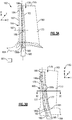
- FIGS 3A through 3C illustrate an exemplary cooling arrangement 178 for an airfoil 162.
- Airfoil 162 is illustrated as a turbine airfoil, such as airfoil 62, but the teachings herein can also be utilized for vane 71 or another portion of the engine 20.
- At least one radial cooling passage 180 (only one shown for illustrative purposes) is provided between pressure and suction sides 173, 174 in a thickness direction T which is generally perpendicular to a chordwise direction C.
- Each radial cooling passage 180 extends from a root section through the platform 164 and toward the tip 165 to communicate coolant to various portions of the airfoil 162.
- An exterior surface of the airfoil 162 may include multiple film cooling holes (not shown) in fluid communication with the radial cooling passages 180 to provide film cooling to various surfaces of the airfoil 162.
- Each radial passage 180 is configured to receive coolant from a coolant source 181 (shown schematically).
- the coolant source 181 is bleed air from an upstream stage of the compressor section 24 or bypass air.
- Other coolant sources are contemplated, such as a secondary cooling system aboard the aircraft.
- the cooling arrangement 178 includes a feeding cavity 182 (or one of a first cavity and a second cavity) and an impingement cavity 184 (or the other one of the first cavity and the second cavity) extending in a radial direction R.
- One of the radial passages 180 communicates coolant to the feeding cavity 182.
- the feeding cavity 182 defines a spanwise axis 185 extending generally in the radial direction R between lateral edges 177 of the feeding cavity 182. Rather, the spanwise axis 185 can have a curvilinear geometry as illustrated in Figure 3B .
- the reference plane extending through the spanwise axis 185 may include an axial twist about the spanwise axis 185 between platform 164 and the tip 165.
- One or more crossover passages 186 are located within an internal wall 190 (shown in Figure 3C ) spacing the feeding cavity 182 and the impingement cavity 184.
- the internal wall 190 defines a reference plane extending in the spanwise or radial direction R along the spanwise axis 185 and through a thickness of the internal wall 190.
- the crossover passages 186 extend in a chordwise direction C to connect the feeding cavity 182 and the impingement cavity 184.
- Each of the crossover passages 186 defines a passage axis 187 arranged such that the passage axis 187 intersects a surface of the impingement cavity 184 and/or the feeding cavity 182.
- Each passage axis 187 defines a vertical angle 189 relative to the spanwise axis 185.
- the arrangement of the crossover passages 186 are such that coolant provided to the feeding cavity 182 is thereafter communicated to the impingement cavity 184 via the crossover passages 186.
- the coolant is communicated to the impingement cavity 184 to selectively provide impingement cooling to one or more external walls 188 of the airfoil 162.
- the crossover passages 186 are staggered in the radial direction R about the spanwise axis 185, as shown in Figure 3B . Rather, the plurality of crossover passages 186 includes a first set of crossover passages 186a and a second set of crossover passages 186b positioned in a thickness direction T on opposite sides of a first reference plane extending through the spanwise axis 185 in the chordwise direction C.
- the crossover passages 186 are shown having a uniform distribution in the radial direction R.
- the airfoil 162 includes a non-uniform distribution of at least some of the crossover passages 186 in the radial direction R.
- the crossover passages 186 can be arranged in other locations of the airfoil 162, including at least one crossover passage 186b located radially below a radially outer surface 61 of the platform 164. In further examples, at least one crossover passage 186b is located radially below the platform 164 and within the root section 68.
- crossover passages 186 can be arranged along a reference plane extending through the spanwise axis 185 and along a reference axis 163 defined by at least one of the feeding cavity 182 and the impingement cavity 184, while other crossover passages 186 can be offset or staggered relative to the reference plane.
- each of the crossover passages 186 is staggered relative to the reference plane extending along the spanwise axis 185 and the reference axis 163.
- crossover passages 186 are described herein as being staggered relative to the reference plane extending through the spanwise axis 185 in the radial direction, it should be understood that the crossover passages described herein can be staggered any direction relative to an airfoil, such as in the chordwise direction and/or thickness direction, in any manner disclosed herein.
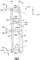
- Figure 4 illustrates a casting core 183 having various vertical arrangements corresponding to various cooling passages 186 of the cooling arrangement 178, for example.
- the casting core 183 includes a first portion 194 corresponding to the feeding cavity 182 and a second portion 196 corresponding to the impingement cavity 184, for example.
- the first portion 194 corresponds to the impingement cavity 184
- the second portion 196 corresponds to the feeding cavity 182.
- Spanwise axis 185 is defined by the first portion 194 corresponding to the feeding cavity 182.
- One or more crossover connectors 192 which correspond to the crossover passages 186, connect the first portion 194 and the second portion 196.
- the crossover connectors 192 cooperate with the first portion 194 and/or the second portion 196 to define an area of inertia generally along the spanwise axis 185.
- the first portion 194 and the second portion 196 are spaced apart in a direction of the axis X, or spanwise direction, to define a length 197 of the crossover connectors 192, which may vary between the first portion 194 and the second portion 196 in a direction of the axis Y, or chordwise direction.
- axis X corresponds to the chordwise direction C of the airfoil 162
- axis Y corresponds to the radial direction R of the airfoil 162
- first portion 194, second portion 196 and crossover connectors 192 corresponding to an airfoil are contemplated.
- Three crossover connectors 192a, 192b, 192c corresponding to three crossover passages 186 of the cooling arrangement 178 are shown for illustrative purposes, although fewer or more than three crossover connectors 192 are contemplated.
- Each of the crossover connectors 192 is arranged relative to the first portion 194 such that the passage axis 187 of the crossover connector 192 defines an angle 189 relative to the spanwise axis 185.
- Each of the crossover connectors 192 can define a different angle 189 relative to the spanwise axis 185.
- the vertical angle 189c of the crossover connector 192c extends radially inward relative to the spanwise axis 185
- the vertical angle 189a of the crossover connector 192a extends radially outward relative to the spanwise axis 185, such that each of the vertical angles 189a, 189c defines an acute angle relative to the spanwise axis 185.
- a difference between at least one of the vertical angles 189a, 189c and the spanwise axis 185 is between about 30° and about 150°.
- Crossover connector 192b is arranged such that the vertical angle 189b relative to the spanwise axis 185 is perpendicular or substantially perpendicular.
- any of the crossover passages 186 can be arranged to define a vertical angle 189 according to any of the crossover connectors 192a, 192b, 192c, and each of the crossover passages 186 can have the same or different vertical angles 189 relative to the spanwise axis 185.
- the crossover connectors 192 are arranged relative to a spanwise axis 185' defined by the second portion 196, and utilizing similar techniques as described herein.
- the vertical arrangement of the crossover connectors 192a, 192b, 192c can be utilized in combination with the staggering of the crossover passages 186 as illustrated in Figure 3B .
- the combination of staggering and the vertical arrangement generally increases the length 197 of each of the crossover connectors 192 corresponding to the crossover passages 186, thereby increasing the convective cooling provided to portions of the airfoil 162 adjacent the crossover passages 186.
- Crossover connectors 192d, 192e illustrate an arrangement corresponding to a pair of crossover passages 186 such that a lateral projection of the passage axis 187d of the first crossover connector 192d intersects a lateral projection of the passage axis 187e of the crossover connector 192e.
- the lateral projections of the passage axis 187d and 187e are relative to a reference plane extending along the X axis and the Y axis.
- the arrangement of the crossover connectors 192d, 192e can be utilized independent of, or in combination with, any of the arrangements illustrated by crossover connectors 192a, 192b and/or 192c, and with any of the crossover passages disclosed herein.
- Each of the crossover connectors 192 defines a cross-sectional width 179 extending through a cross-section of the crossover connector 192.
- the cross-sectional width 179 of each of the crossover connectors 192a, 192b, 192c is equal or substantially equal.
- the cross-sectional width 179 of at least one of the crossover connectors 192a, 192b, 192c is different from at least one of the other crossover connectors 192a, 192b, 192c. This arrangement permits different convective cooling characteristics to portions of the airfoil adjacent the crossover passages 186 due to different cross-sectional areas of the crossover connectors 192.
- FIG. 5A illustrates a cross-sectional top view of an embodiment 200 of an airfoil section 266 having various arrangements of crossover passages 286.
- airfoil section 266 includes at least one pair of crossover passages 286a, 286b configured to provide coolant from a feeding cavity 282a to an impingement cavity 284a located adjacent to a leading edge 267 of the airfoil section 266.
- the crossover passages 286a, 286b are arranged such that a spanwise projection of the passage axis 287a onto a second reference plane generally perpendicular to a first reference plane extending in the radial direction R (shown in Figure 5B ) intersects a spanwise projection of the passage axis 287b.
- the second reference plane generally extends in plane with the cross section of the airfoil section 266 shown in Figure 5A .
- the crossover passages 286a, 286b are staggered in the radial direction as illustrated in Figure 5B .
- Inlets 298a, 298b of the crossover passages 286a, 286b are spaced apart and staggered in the radial direction R, and outlets 299a, 299b of the crossover passages 286a, 286b are also staggered in the radial direction R. In other examples, either the inlets 298 or the outlets 299 are staggered in the radial direction R.
- This arrangement of the crossover passages 286a, 286b provides for an increased length of the crossover passages 286a, 286b compared to crossover passages arranged substantially perpendicular to the respective feeding cavity and/or impingement cavity, such as crossover passages 286c, 286d.
- the internal surface area of the crossover passages 286a, 286b is increased, thereby, permitting additional heat transfer between the surfaces of the crossover passages 286a, 286b and adjacent portions of the airfoil, such as a leading edge 267 of the airfoil section 266 which may experience relatively higher temperatures than a trailing edge 269 of the airfoil section 266.
- the rigidity of the arrangement of the crossover passages 286a, 286b may be different than the rigidity of the crossover connectors forming the crossover passages 286c, 286d.
- the airfoil section 266 can include multiple feeding cavities and impingement cavities to provide cooling to various portions of the airfoil section 266.
- the airfoil section 266 includes a mid-feed cavity 282c spaced from the external walls 288 to provide coolant to a pair of impingement cavities 284c, 284d arranged adjacent to pressure side 273 and suction side 274 of the airfoil section 266, respectively, with crossover passages 286c, 286d staggered in the radial direction R similar to the crossover passages 186 shown in Figure 3B .
- the airfoil section 266 can also include a series of feeding and impingement cavities arranged sequentially with respect to one another.
- a first feeding cavity 282e is arranged with respect to a downstream set of impingement cavities 284e, 284f, 284g, 284h, with impingement cavity 284h bounded by the trailing edge 269 of the airfoil section 266.
- a thermal barrier coating (TBC) 295 is disposed on a surface of the airfoil section 266 to reduce heat transfer between the core airflow path C and the airfoil section 266.
- the thermal barrier coating 295 can be disposed on a surface of the airfoil section 266 utilizing various techniques, such as air plasma spraying or chemical vapor deposition.
- the thermal barrier coating 295 can be made of various materials such as ceramics, alumina, or zirconia, although other materials or composites are also contemplated.
- the thermal barrier coating 295 can taper from the leading edge 267 to the trailing edge 269 of the airfoil section 266 to provide a desired aerodynamic profile.
- Impingement cavity 284h can be fed by crossover passages 286h, in which the spanwise projection of each passage axis 287h does not intersect the other passage axis 287h.
- This arrangement permits coolant to be communicated at a relatively lower temperature than the arrangement of crossover passages 286a, 286b having intersecting spanwise projections, for example.
- Figure 6 illustrates a front view of an exemplary embodiment 300 of a casting core 383 corresponding to a cooling arrangement.
- the casting core 383 includes a plurality of crossover connectors 392 which can correspond to arrangements of the crossover passages 186, 286.
- the casting core 383 includes a first set of crossover connectors 392a and a second set of crossover connectors 392c spaced in the radial direction R between an intermediate set of crossover connectors 392b.
- a cross-sectional width 379b of each of the intermediate set of crossover connectors 392b is different than a cross-sectional width of at least one of the first set of crossover connectors 392a and the second set of crossover connectors 392c.
- a cross-sectional area of each of the intermediate set of crossover connectors 392b is different than a cross-sectional area of at least one of the first set of crossover connectors 392a and the second set of crossover connectors 392c.
- the cross-sectional width 379b of the intermediate set of crossover connectors 392b is less than a cross-sectional width of each of the first set and second set of crossover connectors 392a, 392c.
- a cross-sectional area of at least one of the first set and second set of crossover connectors 392a, 392c to a cross-sectional area of the intermediate set of crossover connectors 392b is less than or equal to about 2:1.
- other cross-sectional arrangements are contemplated herein.
- the casting core 383 can include at least two or more crossover connectors 392d connected to the first portion 394b and a second portion 396c.
- the crossover connectors 392d are positioned on a common side of a reference plane extending through the spanwise axis 385 and at substantially the same radial position along the spanwise axis 385.
- one or more sets of crossover connectors such as crossover connectors 392e, can be substantially aligned on an opposite side of the reference plane relative to the spanwise axis 385 and the crossover connectors 392d. It should be appreciated that the various combinations of any of the crossover connectors 392 can be utilized in any of the cooling arrangements disclosed herein.
- the casting core 383 can include at least two first portions 394a, 394b and at least two second portions 396a, 396b extending in the radial direction R.
- first portion 394a and the second portion 396a share a first set of crossover connectors 392f
- first portion 394b and the second portion 396b share a second, different set of crossover connectors 392g.
- more than two first portions 394 and more than two second portions 396 can be utilized.
- the crossover connectors 392f are arranged such that a spanwise projection of each passage axis 387f intersects each other, similar to the arrangement of the crossover passages 286a, 286b of Figure 5A , whereas a spanwise projection of each passage axis of the crossover connectors 392b do not intersect.
- Figure 7 illustrates a front view of an exemplary embodiment 400 of a casting core 483 illustrating various geometries which can be utilized for any of the crossover passages disclosed herein.
- some of the crossover connectors such as crossover connectors 492a, can have an elliptical cross-sectional profile.
- the crossover connectors can have a racetrack-shaped geometry as illustrated by the crossover connector 492b.
- the crossover passages can also have a rectangular or quadrilateral geometry, such as that illustrated by crossover connector 492c.
- Any of the crossover connectors 492 can be staggered along a reference plane with respect to other crossover connectors in any manner disclosed herein.
- Figures 8A and 8B illustrate an exemplary embodiment 500 of a casting core 583 illustrating various geometries corresponding to crossover passages wherein chordwise projections of the crossover connectors 592 intersect each other.
- the casting core 583 includes at least one pair of crossover connectors 592a, 592b having different radial and lateral orientations relative to a spanwise axis 585.
- the crossover connectors 592a, 592b are arranged to extend between first ends 591a, 591b attached to the first portion 594 and second ends 593a, 593b attached to the second portion 596.
- the first ends 591a, 591b and the second ends 593a, 593b correspond to inlets and outlets of crossover passages disclosed herein.
- the first ends 591a, 591b are arranged at approximately the same radial position relative to the spanwise axis 585, and the second ends 593a, 593b are also arranged at approximately the same radial position such that a projection of passage axis 587a and 587b intersect each other when projected in the chordwise direction C.
- crossover passages corresponding to the crossover connectors 592a, 592b are in fluid communication with each other at the area of intersection.
- the crossover connectors 592a, 592b may have a curved geometry such that the crossover connectors 592a, 592 do not intersect each other.
- the casting core 583 includes at least one pair of crossover connectors 592c, 592d with first ends 591c, 591d staggered and second ends 593c, 593d at least substantially aligned in the radial direction R. In other examples, the casting core 583 includes at least one pair of crossover connectors 592e, 592f with first ends 591e, 591f at least substantially aligned and second ends 593e, 593f staggered in the radial direction R.
- the casting core 583 includes at least one pair of crossover connectors 592g, 592h having first ends 591g, 593h and second ends 593g, 593h staggered relative to the spanwise axis 585.
- the arrangement of the various crossover connectors 592 can further increase a length corresponding to the crossover connectors to provide additional surface area and enhanced heat transfer characteristics.
Landscapes
- Engineering & Computer Science (AREA)
- Mechanical Engineering (AREA)
- General Engineering & Computer Science (AREA)
- Architecture (AREA)
- Turbine Rotor Nozzle Sealing (AREA)
Claims (13)
- Schaufel, umfassend:einen Schaufelteil (266), der eine Außenwand (288) und eine Innenwand (290) aufweist, wobei die Innenwand eine erste Bezugsebene definiert, die sich in einer Spannweitenrichtung und durch eine Dicke der Innenwand erstreckt;einen ersten Hohlraum (282) und einen zweiten Hohlraum (284) die durch die Innenwand getrennt sind;eine Vielzahl von radial versetzten Übergangskanälen (286) innerhalb der Innenwand (290), die den ersten Hohlraum mit dem zweiten Hohlraum verbinden, wobei jeder der Vielzahl von Übergangskanälen eine Kanalachse definiert, wobei jeder der Vielzahl von Übergangskanälen in der Spannweitenrichtung verteilt und derart angeordnet ist, dass die Kanalachse von jedem der Vielzahl von Übergangskanälen eine Oberfläche des zweiten Hohlraums schneidet, undwobei die Vielzahl von Übergangskanälen einen ersten Satz von Übergangskanälen (286) und einen zweiten Satz von Übergangskanälen (286) beinhaltet, die auf gegenüberliegenden Seiten der ersten Bezugsebene positioniert sind, wobei die Kanalachse von jedem von dem ersten Satz von Übergangskanälen in einem ersten vertikalen Winkel bezogen auf eine Spannweitenachse angeordnet ist und die Kanalachse von jedem von dem zweiten Satz von Übergangskanälen in einem zweiten, verschiedenen vertikalen Winkel bezogen auf die Spannweitenachse angeordnet ist,wobei der erste Hohlraum (282c) von der Außenwand (288) beabstandet ist und der zweite Hohlraum (284c, 284d) ein Aufprallhohlraum benachbart zu einer Druckseite (273) oder einer Ansaugseite (274) des Schaufelteils (266) ist.
- Schaufel nach Anspruch 1, wobei die Kanalachse von jedem von der Vielzahl von Übergangskanälen (286) einen stumpfen Winkel bezogen aus die Spannweitenachse definiert.
- Schaufel nach Anspruch 1 oder 2, wobei sich der erste vertikale Winkel bezogen auf die Spannweitenachse radial nach innen erstreckt und sich der zweite vertikale Winkel bezogen auf die Spannweitenachse radial nach außen erstreckt.
- Schaufel nach Anspruch 3, wobei der erste Satz von Übergangskanälen (286) und der zweite Satz von Übergangskanälen (286) derart angeordnet sind, dass ein seitlicher Vorsprung von zumindest einem von dem ersten Satz von Übergangskanälen auf die erste Bezugsebene einen seitlichen Vorsprung von zumindest einem von dem zweiten Satz von Übergangskanälen auf die erste Bezugsebene schneidet.
- Schaufel nach einem der vorangehenden Ansprüche, wobei die Innenwand (290) eine zweite Bezugsebene senkrecht zu der ersten Bezugsebene definiert und der erste Satz von Übergangskanälen und der zweite Satz von Übergangskanälen derart angeordnet sind, das ein Spannweitenvorsprung von zumindest einem von dem ersten Satz von Übergangskanälen auf die zweite Bezugsebene einen Spannweitenvorsprung von zumindest einem von dem zweiten Satz von Übergangskanälen auf die zweite Bezugsebene schneidet.
- Schaufel nach einem der vorangehenden Ansprüche, wobei der erste Satz von Übergangskanälen (392a) und der zweite Satz von Übergangskanälen (392c) in der Spannweitenrichtung zwischen einem Zwischensatz von Übergangskanälen (392b) und einem Querschnittsbereich von jedem von dem Zwischensatz von Übergangskanälen (392b) beabstandet sind, sich von einem Querschnittsbereich von jedem von dem ersten Satz von Übergangskanälen (392a) und dem zweiten Satz von Übergangskanälen (392c) unterscheidet, wobei der Querschnittsbereich des jeden von dem Zwischensatz von Übergangskanälen gegebenenfalls kleiner als der Querschnittsbereich des jeden von dem ersten Satz von Übergangskanälen ist.
- Schaufel nach einem der vorangehenden Ansprüche, wobei der erste Hohlraum (282) konfiguriert ist, um ein Kühlmittel von einer zweiten Vielzahl von Übergangskanälen zu empfangen, wobei die Innenwand gegebenenfalls eine zweite Bezugsebene senkrecht zu der ersten Bezugsebene definiert und die zweite Vielzahl von Übergangskanälen einen dritten Satz von Übergangskanälen und einen vierten Satz von Übergangskanälen beinhaltet, die derart angeordnet sind, dass ein Spannweitenvorsprung von jedem von dem dritten Satz von Übergangskanälen auf die zweite Bezugsebene einen Spannweitenvorsprung von zumindest einem von dem vierten Satz von Übergangskanälen auf die zweite Bezugsebene schneidet.
- Schaufel nach einem der vorangehenden Ansprüche, wobei sich der Schaufelteil (266) von einem Plattenteil (164) erstreckt, wobei der Plattenteil zumindest einen der Vielzahl von Übergangskanälen definiert.
- Schaufel nach einem der vorangehenden Ansprüche, wobei zumindest zwei der Vielzahl von Übergangskanälen (286) im Wesentlichen in der Spannweitenrichtung ausgerichtet und auf einer gemeinsamen Seite der ersten Bezugsebene positioniert sind.
- Schaufel nach einem der vorangehenden Ansprüche, wobei der zweite Hohlraum (284) durch die Außenwand umgrenzt wird.
- Gasturbinentriebwerk, umfassend:einen Rotor und ein Schaufelblatt, das axial von dem Rotor beabstandet ist; undwobei zumindest eines von dem Rotor und dem Schaufelblatt eine Schaufel nach einem der vorangehenden Ansprüche beinhaltet.
- Gusskern (183; 383; 483; 583) für eine Schaufel, die einen Schaufelteil (266) aufweist, der eine Außenwand (288) und eine Innenwand (290) aufweist, wobei die Innenwand eine erste Bezugsebene definiert, die sich in einer Spannweitenrichtung und durch eine Dicke der Innenwand erstreckt, wobei der Gusskern Folgendes umfasst:einen ersten Abschnitt (194; 394; 494; 594), der einem ersten Hohlraum (282c) einer Schaufel entspricht, und einen zweiten Abschnitt (196; 396; 496; 596), der einem zweiten Hohlraum (284c, 284d) der Schaufel entspricht, wobei sich jeder von dem ersten Abschnitt und dem zweiten Abschnitt in einer Spannweitenrichtung entlang der ersten Bezugsebene erstreckt;eine Vielzahl von radial versetzten Verbindern (192; 392; 492; 592), die den ersten Abschnitt an den zweiten Abschnitt koppelt, wobei die Vielzahl von Verbindern einer Vielzahl von Übergangskanälen (286) der Schaufel entspricht, wobei jeder von der Vielzahl von Verbindern eine erste Achse definiert, wobei die Vielzahl von Verbindern in der Spannweitenrichtung verteilt sind; undwobei die Vielzahl von Verbindern einen ersten Satz von Verbindern und einen zweiten Satz von Verbindern beinhaltet, die auf gegenüberliegenden Seiten der ersten Bezugsebene positioniert sind, wobei die erste Achse von jedem von dem ersten Satz von Verbindern in einem ersten vertikalen Winkel bezogen auf die Spannweitenachse angeordnet ist und die erste Achse von jedem von dem zweiten Satz von Verbindern in einem zweiten, verschiedenen vertikalen Winkel bezogen auf die Spannweitenwachse angeordnet ist,wobei der erste Hohlraum (282c) von der Außenwand (288) beabstandet ist und der zweite Hohlraum (284c, 284d) ein Aufprallhohlraum benachbart zu einer Druckseite (273) oder einer Ansaugseite (274) des Schaufelteils (266) ist.
- Gusskern (183; 383; 483; 583) für eine Schaufel nach Anspruch 12, wobei sich der erste Abschnitt (194; 394; 494; 594) und der zweite Abschnitt (196; 396; 496; 596) in einer Sehnenrichtung entlang einer zweiten Bezugsebene senkrecht zu der ersten Bezugsebene erstrecken und der erste Satz von Verbindern (192; 392; 492; 592) und der zweite Satz von Verbindern (192; 392; 492; 592) derart angeordnet sind, dass ein Spannweitenvorsprung von jedem von dem ersten Satz von Verbindern auf die zweite Bezugsebene einen Spannweitenvorsprung von zumindest einem von dem zweiten Satz von Verbindern auf die zweite Bezugsebene schneidet.
Applications Claiming Priority (1)
| Application Number | Priority Date | Filing Date | Title |
|---|---|---|---|
| US201462045583P | 2014-09-04 | 2014-09-04 |
Publications (2)
| Publication Number | Publication Date |
|---|---|
| EP2993302A1 EP2993302A1 (de) | 2016-03-09 |
| EP2993302B1 true EP2993302B1 (de) | 2020-06-10 |
Family
ID=54062644
Family Applications (1)
| Application Number | Title | Priority Date | Filing Date |
|---|---|---|---|
| EP15183628.5A Active EP2993302B1 (de) | 2014-09-04 | 2015-09-03 | Schaufel mit versetzten übergangskanälen und zugehöriger gusskern |
Country Status (2)
| Country | Link |
|---|---|
| US (1) | US10145246B2 (de) |
| EP (1) | EP2993302B1 (de) |
Families Citing this family (13)
| Publication number | Priority date | Publication date | Assignee | Title |
|---|---|---|---|---|
| US10208603B2 (en) | 2014-11-18 | 2019-02-19 | United Technologies Corporation | Staggered crossovers for airfoils |
| US10190420B2 (en) * | 2015-02-10 | 2019-01-29 | United Technologies Corporation | Flared crossovers for airfoils |
| WO2017074404A1 (en) * | 2015-10-30 | 2017-05-04 | Siemens Aktiengesellschaft | Turbine airfoil with offset impingement cooling at leading edge |
| DE102015224259A1 (de) * | 2015-12-04 | 2017-06-08 | MTU Aero Engines AG | Auflauffläche für Leitschaufeldeck- und Laufschaufelgrundplatte |
| US10738700B2 (en) * | 2016-11-16 | 2020-08-11 | General Electric Company | Turbine assembly |
| US10830058B2 (en) * | 2016-11-30 | 2020-11-10 | Rolls-Royce Corporation | Turbine engine components with cooling features |
| US11021967B2 (en) * | 2017-04-03 | 2021-06-01 | General Electric Company | Turbine engine component with a core tie hole |
| DE102018203211A1 (de) * | 2018-03-05 | 2019-09-05 | MTU Aero Engines AG | Schaufel mit Hitzeschild und Strömungsmaschine |
| US10975710B2 (en) * | 2018-12-05 | 2021-04-13 | Raytheon Technologies Corporation | Cooling circuit for gas turbine engine component |
| US12215601B2 (en) * | 2023-02-17 | 2025-02-04 | Rtx Corporation | Air foil with staggered cooling hole configuration |
| US12442305B2 (en) | 2023-06-01 | 2025-10-14 | General Electric Company | Composite airfoil assembly for a turbine engine |
| US12392246B2 (en) | 2023-06-12 | 2025-08-19 | Rtx Corporation | Airfoil cooling circuit |
| US12012866B1 (en) * | 2023-06-12 | 2024-06-18 | Rtx Corporation | Non-circular stress reducing crossover |
Family Cites Families (15)
| Publication number | Priority date | Publication date | Assignee | Title |
|---|---|---|---|---|
| US4080095A (en) | 1976-09-02 | 1978-03-21 | Westinghouse Electric Corporation | Cooled turbine vane |
| GB2260166B (en) | 1985-10-18 | 1993-06-30 | Rolls Royce | Cooled aerofoil blade or vane for a gas turbine engine |
| US5246340A (en) | 1991-11-19 | 1993-09-21 | Allied-Signal Inc. | Internally cooled airfoil |
| US6206638B1 (en) | 1999-02-12 | 2001-03-27 | General Electric Company | Low cost airfoil cooling circuit with sidewall impingement cooling chambers |
| GB0127902D0 (en) | 2001-11-21 | 2002-01-16 | Rolls Royce Plc | Gas turbine engine aerofoil |
| GB2401915B (en) | 2003-05-23 | 2006-06-14 | Rolls Royce Plc | Turbine blade |
| DE10332563A1 (de) | 2003-07-11 | 2005-01-27 | Rolls-Royce Deutschland Ltd & Co Kg | Turbinenschaufel mit Prallkühlung |
| GB2420156B (en) | 2004-11-16 | 2007-01-24 | Rolls Royce Plc | A heat transfer arrangement |
| EP1847684A1 (de) | 2006-04-21 | 2007-10-24 | Siemens Aktiengesellschaft | Turbinenschaufel |
| US7722326B2 (en) | 2007-03-13 | 2010-05-25 | Siemens Energy, Inc. | Intensively cooled trailing edge of thin airfoils for turbine engines |
| GB0811391D0 (en) | 2008-06-23 | 2008-07-30 | Rolls Royce Plc | A rotor blade |
| CN102753787B (zh) * | 2009-10-20 | 2015-11-25 | 西门子能量股份有限公司 | 具有锥形冷却通路的翼型 |
| US8317474B1 (en) | 2010-01-19 | 2012-11-27 | Florida Turbine Technologies, Inc. | Turbine blade with near wall cooling |
| US8714926B2 (en) | 2010-09-17 | 2014-05-06 | Siemens Energy, Inc. | Turbine component cooling channel mesh with intersection chambers |
| US9376922B2 (en) | 2013-01-09 | 2016-06-28 | General Electric Company | Interior configuration for turbine rotor blade |
-
2015
- 2015-08-07 US US14/820,786 patent/US10145246B2/en active Active
- 2015-09-03 EP EP15183628.5A patent/EP2993302B1/de active Active
Non-Patent Citations (1)
| Title |
|---|
| None * |
Also Published As
| Publication number | Publication date |
|---|---|
| US20160160657A1 (en) | 2016-06-09 |
| US10145246B2 (en) | 2018-12-04 |
| EP2993302A1 (de) | 2016-03-09 |
Similar Documents
| Publication | Publication Date | Title |
|---|---|---|
| EP2993302A1 (de) | Schaufel mit versetzten übergangskanälen und zugehöriger gusskern | |
| US11148191B2 (en) | Core arrangement for turbine engine component | |
| EP3032035B1 (de) | Versetzte übergänge für tragflächen | |
| US10253635B2 (en) | Blade tip cooling arrangement | |
| US10041358B2 (en) | Gas turbine engine blade squealer pockets | |
| EP3444436B1 (de) | Direktionale kühlanordnung für turbinenschaufel | |
| US10677069B2 (en) | Component core with shaped edges | |
| EP3342982B1 (de) | Geneigte verbindungskanäle zwischen internen schaufelkammern | |
| US20180058224A1 (en) | Gas turbine blade with tip cooling | |
| US10982552B2 (en) | Gas turbine engine component with film cooling hole | |
| EP3034793B1 (de) | Gasturbinenmotorkomponente mit erhöhter kühlleistung | |
| US20160326898A1 (en) | Seal arrangement for turbine engine component | |
| US20160047251A1 (en) | Cooling hole having unique meter portion | |
| EP3078807B2 (de) | Kühlkanäle für eine gasturbinenmotorkomponente | |
| EP3511523B1 (de) | Prallkühlanordnung für schaufelprofile |
Legal Events
| Date | Code | Title | Description |
|---|---|---|---|
| PUAI | Public reference made under article 153(3) epc to a published international application that has entered the european phase |
Free format text: ORIGINAL CODE: 0009012 |
|
| AK | Designated contracting states |
Kind code of ref document: A1 Designated state(s): AL AT BE BG CH CY CZ DE DK EE ES FI FR GB GR HR HU IE IS IT LI LT LU LV MC MK MT NL NO PL PT RO RS SE SI SK SM TR |
|
| AX | Request for extension of the european patent |
Extension state: BA ME |
|
| RIN1 | Information on inventor provided before grant (corrected) |
Inventor name: LEWIS, SCOTT D. Inventor name: CORCORAN, CHRISTOPHER Inventor name: GIRMA, YAFET |
|
| 17P | Request for examination filed |
Effective date: 20160907 |
|
| RBV | Designated contracting states (corrected) |
Designated state(s): AL AT BE BG CH CY CZ DE DK EE ES FI FR GB GR HR HU IE IS IT LI LT LU LV MC MK MT NL NO PL PT RO RS SE SI SK SM TR |
|
| RAP1 | Party data changed (applicant data changed or rights of an application transferred) |
Owner name: UNITED TECHNOLOGIES CORPORATION |
|
| STAA | Information on the status of an ep patent application or granted ep patent |
Free format text: STATUS: EXAMINATION IS IN PROGRESS |
|
| 17Q | First examination report despatched |
Effective date: 20181210 |
|
| GRAP | Despatch of communication of intention to grant a patent |
Free format text: ORIGINAL CODE: EPIDOSNIGR1 |
|
| STAA | Information on the status of an ep patent application or granted ep patent |
Free format text: STATUS: GRANT OF PATENT IS INTENDED |
|
| INTG | Intention to grant announced |
Effective date: 20191218 |
|
| GRAS | Grant fee paid |
Free format text: ORIGINAL CODE: EPIDOSNIGR3 |
|
| GRAA | (expected) grant |
Free format text: ORIGINAL CODE: 0009210 |
|
| STAA | Information on the status of an ep patent application or granted ep patent |
Free format text: STATUS: THE PATENT HAS BEEN GRANTED |
|
| AK | Designated contracting states |
Kind code of ref document: B1 Designated state(s): AL AT BE BG CH CY CZ DE DK EE ES FI FR GB GR HR HU IE IS IT LI LT LU LV MC MK MT NL NO PL PT RO RS SE SI SK SM TR |
|
| REG | Reference to a national code |
Ref country code: GB Ref legal event code: FG4D |
|
| REG | Reference to a national code |
Ref country code: CH Ref legal event code: EP Ref country code: AT Ref legal event code: REF Ref document number: 1279347 Country of ref document: AT Kind code of ref document: T Effective date: 20200615 |
|
| REG | Reference to a national code |
Ref country code: DE Ref legal event code: R096 Ref document number: 602015054015 Country of ref document: DE |
|
| REG | Reference to a national code |
Ref country code: IE Ref legal event code: FG4D |
|
| REG | Reference to a national code |
Ref country code: LT Ref legal event code: MG4D |
|
| PG25 | Lapsed in a contracting state [announced via postgrant information from national office to epo] |
Ref country code: SE Free format text: LAPSE BECAUSE OF FAILURE TO SUBMIT A TRANSLATION OF THE DESCRIPTION OR TO PAY THE FEE WITHIN THE PRESCRIBED TIME-LIMIT Effective date: 20200610 Ref country code: LT Free format text: LAPSE BECAUSE OF FAILURE TO SUBMIT A TRANSLATION OF THE DESCRIPTION OR TO PAY THE FEE WITHIN THE PRESCRIBED TIME-LIMIT Effective date: 20200610 Ref country code: GR Free format text: LAPSE BECAUSE OF FAILURE TO SUBMIT A TRANSLATION OF THE DESCRIPTION OR TO PAY THE FEE WITHIN THE PRESCRIBED TIME-LIMIT Effective date: 20200911 Ref country code: NO Free format text: LAPSE BECAUSE OF FAILURE TO SUBMIT A TRANSLATION OF THE DESCRIPTION OR TO PAY THE FEE WITHIN THE PRESCRIBED TIME-LIMIT Effective date: 20200910 Ref country code: FI Free format text: LAPSE BECAUSE OF FAILURE TO SUBMIT A TRANSLATION OF THE DESCRIPTION OR TO PAY THE FEE WITHIN THE PRESCRIBED TIME-LIMIT Effective date: 20200610 |
|
| REG | Reference to a national code |
Ref country code: NL Ref legal event code: MP Effective date: 20200610 |
|
| PG25 | Lapsed in a contracting state [announced via postgrant information from national office to epo] |
Ref country code: LV Free format text: LAPSE BECAUSE OF FAILURE TO SUBMIT A TRANSLATION OF THE DESCRIPTION OR TO PAY THE FEE WITHIN THE PRESCRIBED TIME-LIMIT Effective date: 20200610 Ref country code: RS Free format text: LAPSE BECAUSE OF FAILURE TO SUBMIT A TRANSLATION OF THE DESCRIPTION OR TO PAY THE FEE WITHIN THE PRESCRIBED TIME-LIMIT Effective date: 20200610 Ref country code: HR Free format text: LAPSE BECAUSE OF FAILURE TO SUBMIT A TRANSLATION OF THE DESCRIPTION OR TO PAY THE FEE WITHIN THE PRESCRIBED TIME-LIMIT Effective date: 20200610 Ref country code: BG Free format text: LAPSE BECAUSE OF FAILURE TO SUBMIT A TRANSLATION OF THE DESCRIPTION OR TO PAY THE FEE WITHIN THE PRESCRIBED TIME-LIMIT Effective date: 20200910 |
|
| REG | Reference to a national code |
Ref country code: AT Ref legal event code: MK05 Ref document number: 1279347 Country of ref document: AT Kind code of ref document: T Effective date: 20200610 |
|
| PG25 | Lapsed in a contracting state [announced via postgrant information from national office to epo] |
Ref country code: NL Free format text: LAPSE BECAUSE OF FAILURE TO SUBMIT A TRANSLATION OF THE DESCRIPTION OR TO PAY THE FEE WITHIN THE PRESCRIBED TIME-LIMIT Effective date: 20200610 Ref country code: AL Free format text: LAPSE BECAUSE OF FAILURE TO SUBMIT A TRANSLATION OF THE DESCRIPTION OR TO PAY THE FEE WITHIN THE PRESCRIBED TIME-LIMIT Effective date: 20200610 |
|
| PG25 | Lapsed in a contracting state [announced via postgrant information from national office to epo] |
Ref country code: CZ Free format text: LAPSE BECAUSE OF FAILURE TO SUBMIT A TRANSLATION OF THE DESCRIPTION OR TO PAY THE FEE WITHIN THE PRESCRIBED TIME-LIMIT Effective date: 20200610 Ref country code: IT Free format text: LAPSE BECAUSE OF FAILURE TO SUBMIT A TRANSLATION OF THE DESCRIPTION OR TO PAY THE FEE WITHIN THE PRESCRIBED TIME-LIMIT Effective date: 20200610 Ref country code: PT Free format text: LAPSE BECAUSE OF FAILURE TO SUBMIT A TRANSLATION OF THE DESCRIPTION OR TO PAY THE FEE WITHIN THE PRESCRIBED TIME-LIMIT Effective date: 20201012 Ref country code: EE Free format text: LAPSE BECAUSE OF FAILURE TO SUBMIT A TRANSLATION OF THE DESCRIPTION OR TO PAY THE FEE WITHIN THE PRESCRIBED TIME-LIMIT Effective date: 20200610 Ref country code: ES Free format text: LAPSE BECAUSE OF FAILURE TO SUBMIT A TRANSLATION OF THE DESCRIPTION OR TO PAY THE FEE WITHIN THE PRESCRIBED TIME-LIMIT Effective date: 20200610 Ref country code: SM Free format text: LAPSE BECAUSE OF FAILURE TO SUBMIT A TRANSLATION OF THE DESCRIPTION OR TO PAY THE FEE WITHIN THE PRESCRIBED TIME-LIMIT Effective date: 20200610 Ref country code: RO Free format text: LAPSE BECAUSE OF FAILURE TO SUBMIT A TRANSLATION OF THE DESCRIPTION OR TO PAY THE FEE WITHIN THE PRESCRIBED TIME-LIMIT Effective date: 20200610 Ref country code: AT Free format text: LAPSE BECAUSE OF FAILURE TO SUBMIT A TRANSLATION OF THE DESCRIPTION OR TO PAY THE FEE WITHIN THE PRESCRIBED TIME-LIMIT Effective date: 20200610 |
|
| PG25 | Lapsed in a contracting state [announced via postgrant information from national office to epo] |
Ref country code: PL Free format text: LAPSE BECAUSE OF FAILURE TO SUBMIT A TRANSLATION OF THE DESCRIPTION OR TO PAY THE FEE WITHIN THE PRESCRIBED TIME-LIMIT Effective date: 20200610 Ref country code: SK Free format text: LAPSE BECAUSE OF FAILURE TO SUBMIT A TRANSLATION OF THE DESCRIPTION OR TO PAY THE FEE WITHIN THE PRESCRIBED TIME-LIMIT Effective date: 20200610 Ref country code: IS Free format text: LAPSE BECAUSE OF FAILURE TO SUBMIT A TRANSLATION OF THE DESCRIPTION OR TO PAY THE FEE WITHIN THE PRESCRIBED TIME-LIMIT Effective date: 20201010 |
|
| REG | Reference to a national code |
Ref country code: DE Ref legal event code: R097 Ref document number: 602015054015 Country of ref document: DE |
|
| RAP2 | Party data changed (patent owner data changed or rights of a patent transferred) |
Owner name: RAYTHEON TECHNOLOGIES CORPORATION |
|
| PLBE | No opposition filed within time limit |
Free format text: ORIGINAL CODE: 0009261 |
|
| STAA | Information on the status of an ep patent application or granted ep patent |
Free format text: STATUS: NO OPPOSITION FILED WITHIN TIME LIMIT |
|
| PG25 | Lapsed in a contracting state [announced via postgrant information from national office to epo] |
Ref country code: MC Free format text: LAPSE BECAUSE OF FAILURE TO SUBMIT A TRANSLATION OF THE DESCRIPTION OR TO PAY THE FEE WITHIN THE PRESCRIBED TIME-LIMIT Effective date: 20200610 Ref country code: DK Free format text: LAPSE BECAUSE OF FAILURE TO SUBMIT A TRANSLATION OF THE DESCRIPTION OR TO PAY THE FEE WITHIN THE PRESCRIBED TIME-LIMIT Effective date: 20200610 |
|
| REG | Reference to a national code |
Ref country code: CH Ref legal event code: PL |
|
| 26N | No opposition filed |
Effective date: 20210311 |
|
| PG25 | Lapsed in a contracting state [announced via postgrant information from national office to epo] |
Ref country code: SI Free format text: LAPSE BECAUSE OF FAILURE TO SUBMIT A TRANSLATION OF THE DESCRIPTION OR TO PAY THE FEE WITHIN THE PRESCRIBED TIME-LIMIT Effective date: 20200610 |
|
| REG | Reference to a national code |
Ref country code: BE Ref legal event code: MM Effective date: 20200930 |
|
| PG25 | Lapsed in a contracting state [announced via postgrant information from national office to epo] |
Ref country code: LU Free format text: LAPSE BECAUSE OF NON-PAYMENT OF DUE FEES Effective date: 20200903 |
|
| PG25 | Lapsed in a contracting state [announced via postgrant information from national office to epo] |
Ref country code: BE Free format text: LAPSE BECAUSE OF NON-PAYMENT OF DUE FEES Effective date: 20200930 Ref country code: CH Free format text: LAPSE BECAUSE OF NON-PAYMENT OF DUE FEES Effective date: 20200930 Ref country code: IE Free format text: LAPSE BECAUSE OF NON-PAYMENT OF DUE FEES Effective date: 20200903 Ref country code: LI Free format text: LAPSE BECAUSE OF NON-PAYMENT OF DUE FEES Effective date: 20200930 |
|
| PG25 | Lapsed in a contracting state [announced via postgrant information from national office to epo] |
Ref country code: TR Free format text: LAPSE BECAUSE OF FAILURE TO SUBMIT A TRANSLATION OF THE DESCRIPTION OR TO PAY THE FEE WITHIN THE PRESCRIBED TIME-LIMIT Effective date: 20200610 Ref country code: MT Free format text: LAPSE BECAUSE OF FAILURE TO SUBMIT A TRANSLATION OF THE DESCRIPTION OR TO PAY THE FEE WITHIN THE PRESCRIBED TIME-LIMIT Effective date: 20200610 Ref country code: CY Free format text: LAPSE BECAUSE OF FAILURE TO SUBMIT A TRANSLATION OF THE DESCRIPTION OR TO PAY THE FEE WITHIN THE PRESCRIBED TIME-LIMIT Effective date: 20200610 |
|
| PG25 | Lapsed in a contracting state [announced via postgrant information from national office to epo] |
Ref country code: MK Free format text: LAPSE BECAUSE OF FAILURE TO SUBMIT A TRANSLATION OF THE DESCRIPTION OR TO PAY THE FEE WITHIN THE PRESCRIBED TIME-LIMIT Effective date: 20200610 |
|
| P01 | Opt-out of the competence of the unified patent court (upc) registered |
Effective date: 20230520 |
|
| REG | Reference to a national code |
Ref country code: DE Ref legal event code: R081 Ref document number: 602015054015 Country of ref document: DE Owner name: RTX CORPORATION (N.D.GES.D. STAATES DELAWARE),, US Free format text: FORMER OWNER: UNITED TECHNOLOGIES CORP., FARMINGTON, CONN., US |
|
| PGFP | Annual fee paid to national office [announced via postgrant information from national office to epo] |
Ref country code: DE Payment date: 20250820 Year of fee payment: 11 |
|
| PGFP | Annual fee paid to national office [announced via postgrant information from national office to epo] |
Ref country code: GB Payment date: 20250820 Year of fee payment: 11 |
|
| PGFP | Annual fee paid to national office [announced via postgrant information from national office to epo] |
Ref country code: FR Payment date: 20250820 Year of fee payment: 11 |