EP2993293A1 - Concealed door operator - Google Patents
Concealed door operator Download PDFInfo
- Publication number
- EP2993293A1 EP2993293A1 EP14003054.5A EP14003054A EP2993293A1 EP 2993293 A1 EP2993293 A1 EP 2993293A1 EP 14003054 A EP14003054 A EP 14003054A EP 2993293 A1 EP2993293 A1 EP 2993293A1
- Authority
- EP
- European Patent Office
- Prior art keywords
- door operator
- housing
- concealed door
- face
- operating unit
- Prior art date
- Legal status (The legal status is an assumption and is not a legal conclusion. Google has not performed a legal analysis and makes no representation as to the accuracy of the status listed.)
- Withdrawn
Links
- 238000013016 damping Methods 0.000 claims description 8
- 230000001131 transforming effect Effects 0.000 claims description 4
- 229920003266 Leaf® Polymers 0.000 description 14
- 238000009434 installation Methods 0.000 description 5
- 238000004519 manufacturing process Methods 0.000 description 5
- XEEYBQQBJWHFJM-UHFFFAOYSA-N Iron Chemical compound [Fe] XEEYBQQBJWHFJM-UHFFFAOYSA-N 0.000 description 2
- 238000004512 die casting Methods 0.000 description 2
- 230000002708 enhancing effect Effects 0.000 description 2
- 238000011900 installation process Methods 0.000 description 2
- 239000000463 material Substances 0.000 description 2
- 238000000034 method Methods 0.000 description 2
- XAGFODPZIPBFFR-UHFFFAOYSA-N aluminium Chemical compound [Al] XAGFODPZIPBFFR-UHFFFAOYSA-N 0.000 description 1
- 229910052782 aluminium Inorganic materials 0.000 description 1
- 230000001419 dependent effect Effects 0.000 description 1
- 229910052742 iron Inorganic materials 0.000 description 1
- 238000012423 maintenance Methods 0.000 description 1
Images

Classifications
-
- E—FIXED CONSTRUCTIONS
- E05—LOCKS; KEYS; WINDOW OR DOOR FITTINGS; SAFES
- E05F—DEVICES FOR MOVING WINGS INTO OPEN OR CLOSED POSITION; CHECKS FOR WINGS; WING FITTINGS NOT OTHERWISE PROVIDED FOR, CONCERNED WITH THE FUNCTIONING OF THE WING
- E05F3/00—Closers or openers with braking devices, e.g. checks; Construction of pneumatic or liquid braking devices
- E05F3/04—Closers or openers with braking devices, e.g. checks; Construction of pneumatic or liquid braking devices with liquid piston brakes
- E05F3/10—Closers or openers with braking devices, e.g. checks; Construction of pneumatic or liquid braking devices with liquid piston brakes with a spring, other than a torsion spring, and a piston, the axes of which are the same or lie in the same direction
-
- E—FIXED CONSTRUCTIONS
- E05—LOCKS; KEYS; WINDOW OR DOOR FITTINGS; SAFES
- E05F—DEVICES FOR MOVING WINGS INTO OPEN OR CLOSED POSITION; CHECKS FOR WINGS; WING FITTINGS NOT OTHERWISE PROVIDED FOR, CONCERNED WITH THE FUNCTIONING OF THE WING
- E05F3/00—Closers or openers with braking devices, e.g. checks; Construction of pneumatic or liquid braking devices
- E05F3/04—Closers or openers with braking devices, e.g. checks; Construction of pneumatic or liquid braking devices with liquid piston brakes
- E05F3/10—Closers or openers with braking devices, e.g. checks; Construction of pneumatic or liquid braking devices with liquid piston brakes with a spring, other than a torsion spring, and a piston, the axes of which are the same or lie in the same direction
- E05F3/102—Closers or openers with braking devices, e.g. checks; Construction of pneumatic or liquid braking devices with liquid piston brakes with a spring, other than a torsion spring, and a piston, the axes of which are the same or lie in the same direction with rack-and-pinion transmission between driving shaft and piston within the closer housing
-
- E—FIXED CONSTRUCTIONS
- E05—LOCKS; KEYS; WINDOW OR DOOR FITTINGS; SAFES
- E05F—DEVICES FOR MOVING WINGS INTO OPEN OR CLOSED POSITION; CHECKS FOR WINGS; WING FITTINGS NOT OTHERWISE PROVIDED FOR, CONCERNED WITH THE FUNCTIONING OF THE WING
- E05F3/00—Closers or openers with braking devices, e.g. checks; Construction of pneumatic or liquid braking devices
- E05F3/04—Closers or openers with braking devices, e.g. checks; Construction of pneumatic or liquid braking devices with liquid piston brakes
- E05F3/10—Closers or openers with braking devices, e.g. checks; Construction of pneumatic or liquid braking devices with liquid piston brakes with a spring, other than a torsion spring, and a piston, the axes of which are the same or lie in the same direction
- E05F3/104—Closers or openers with braking devices, e.g. checks; Construction of pneumatic or liquid braking devices with liquid piston brakes with a spring, other than a torsion spring, and a piston, the axes of which are the same or lie in the same direction with cam-and-slide transmission between driving shaft and piston within the closer housing
-
- E—FIXED CONSTRUCTIONS
- E05—LOCKS; KEYS; WINDOW OR DOOR FITTINGS; SAFES
- E05F—DEVICES FOR MOVING WINGS INTO OPEN OR CLOSED POSITION; CHECKS FOR WINGS; WING FITTINGS NOT OTHERWISE PROVIDED FOR, CONCERNED WITH THE FUNCTIONING OF THE WING
- E05F3/00—Closers or openers with braking devices, e.g. checks; Construction of pneumatic or liquid braking devices
- E05F3/22—Additional arrangements for closers, e.g. for holding the wing in opened or other position
- E05F3/225—Additional arrangements for closers, e.g. for holding the wing in opened or other position mounted at the bottom of wings, e.g. details related to seals, covers, connections to the wings, embedding in the floor
-
- E—FIXED CONSTRUCTIONS
- E05—LOCKS; KEYS; WINDOW OR DOOR FITTINGS; SAFES
- E05Y—INDEXING SCHEME ASSOCIATED WITH SUBCLASSES E05D AND E05F, RELATING TO CONSTRUCTION ELEMENTS, ELECTRIC CONTROL, POWER SUPPLY, POWER SIGNAL OR TRANSMISSION, USER INTERFACES, MOUNTING OR COUPLING, DETAILS, ACCESSORIES, AUXILIARY OPERATIONS NOT OTHERWISE PROVIDED FOR, APPLICATION THEREOF
- E05Y2201/00—Constructional elements; Accessories therefor
- E05Y2201/10—Covers; Housings
-
- E—FIXED CONSTRUCTIONS
- E05—LOCKS; KEYS; WINDOW OR DOOR FITTINGS; SAFES
- E05Y—INDEXING SCHEME ASSOCIATED WITH SUBCLASSES E05D AND E05F, RELATING TO CONSTRUCTION ELEMENTS, ELECTRIC CONTROL, POWER SUPPLY, POWER SIGNAL OR TRANSMISSION, USER INTERFACES, MOUNTING OR COUPLING, DETAILS, ACCESSORIES, AUXILIARY OPERATIONS NOT OTHERWISE PROVIDED FOR, APPLICATION THEREOF
- E05Y2600/00—Mounting or coupling arrangements for elements provided for in this subclass
- E05Y2600/40—Mounting location; Visibility of the elements
- E05Y2600/41—Concealed
-
- E—FIXED CONSTRUCTIONS
- E05—LOCKS; KEYS; WINDOW OR DOOR FITTINGS; SAFES
- E05Y—INDEXING SCHEME ASSOCIATED WITH SUBCLASSES E05D AND E05F, RELATING TO CONSTRUCTION ELEMENTS, ELECTRIC CONTROL, POWER SUPPLY, POWER SIGNAL OR TRANSMISSION, USER INTERFACES, MOUNTING OR COUPLING, DETAILS, ACCESSORIES, AUXILIARY OPERATIONS NOT OTHERWISE PROVIDED FOR, APPLICATION THEREOF
- E05Y2600/00—Mounting or coupling arrangements for elements provided for in this subclass
- E05Y2600/40—Mounting location; Visibility of the elements
- E05Y2600/46—Mounting location; Visibility of the elements in or on the wing
Definitions
- the present invention regards concealed door operators. Such door operators are used for providing an opening or closing force to a door.
- concealed door operators are well-known from the prior art. Concealed door operators are hidden within a door leaf or a floor or a wall, such that no visible unit needs to be provided on the door. In case of installation within a cavity of a door leaf, the width of the cavity is limited by the thickness of the door leaf. For maximum residual strength, of the door, the width of the cavity should be just wide enough to accommodate the door closer. This leaves very little clearance between the outer wall of the concealed door operator and the inner wall of the door cavity. The installer has to take extra care to align the housing to the cavity. If the clearance is tight, additional effort is required to press the closer into position within the cavity.
- a concealed door operator comprising an operating unit and a housing.
- the housing comprises a top face and an opposing bottom face. Further, the housing comprises at least one side face between the bottom face and the top face.
- the operating unit comprises a square pinion protruding from the top face and allowing transmittal of torque from or to the operation unit. Further, the operating unit is provided within the housing. In a preferred embodiment, the whole operating unit is provided within the housing with the square pinion being the only part of the operating unit which is accessible from outside the housing. At least one side face is inclined such that the bottom face is smaller than the top face.
- said at least one side face is angulated inward such that an angle between a vertical plate and the side face remains.
- the inclination is preferably selected between 0.2 and 1.5 degrees, in particular between 0.5 and 1.0 degrees. Due to the inclination of said side face, the maximum dimensions of the bottom face are smaller than the dimensions of the top face. However, the bottom face could be smaller than caused by the inclination by providing a step in said side face.
- Such a design provides the best capability of installing the concealed door operator. Since the concealed door operator has to be provided within a cavity of a door leaf, a floor or a wall, the inclination of the side face provides a lead-in to the cavity.
- the concealed door operator comprises at least two opposing side faces, wherein the two opposing side faces are inclined in an opposite manner.
- the opposing side faces are both inclined inward.
- the dimensions of the bottom face have to be smaller than the dimensions of the top face due to the inclination.
- the inclined side faces are symmetrically.
- the concealed door operator is preferably characterized in that the housing is a cast housing.
- the cast housing can be provided with stiffening means or enhanced wall sections. Further, any cast housing is simple to manufacture and low in cost. Nevertheless, the cast housing is designed to provide maximum durability during the lifecycle of the concealed door operator. Due to the inclination of the side face, there is a draft angle to facilitate the ejection of the raw housing from the mold during production, for example by the pressure die casting process.
- the top face comprises mounting features for mounting the concealed door operator within a door leaf or a floor or a wall.
- the mounting features can be flanges or boreholes for mounting the concealed door operator.
- the mounting features are integrally mounted with the housing.
- the housing has a prismatic shape, wherein the flanges are provided on base faces of the prism.
- Such a design minimizes the room required for mounting the concealed door operator.
- the concealed door operator can therefore be installed into door leafs having a very narrow width.
- the housing preferably has a prismatic shape, while the inclined side face is a face other than the base faces. With both faces inclined, the above mentioned advantages regarding lead-in and ejection from the mold are further enhanced.
- the concealed door operator further preferably comprises a cover plate.
- the housing preferably comprises a cavity resulting in a cutout of the top face.
- the cavity is covered by said cover plate, wherein the cover plate is fixed only to the housing.
- the cover plate is smaller than the top face such that the top face functions as frame for the cover plate.
- the operating unit is a door closing unit. Therefore, the door can be opened manually and is closed by the concealed door operator. Since the door operator is concealed, there is no visible unit provided on the door such that an esthetic appeal is maintained.
- the operating unit comprises an operating piston and a damping piston. Both, the operating piston and the damping piston are engaged with a pinion cam for transforming the longitudinal movement of the pistons into a rotational movement of the pinion cam.
- the concealed door operator can be installed in any door independent from the opening direction of the door.
- the pinion cam can be rotated clockwise or counterclockwise while in both cases load is provided to the operating unit.
- the operating unit also comprises an operating piston and a damping piston.
- the operating piston and the damping piston are connected to a rack with a pinion engaged with the rack for transforming the longitudinal movement of the pistons and the rack into a rotational movement of the pinion.
- This design allows an installation of the concealed door operator only in doors having a predetermined opening direction. Therefore, the concealed door operator is preferably provided in two versions, in the one version the pinion needs to be rotated clockwise for providing load to the operating unit, in the other version the pinion needs to be rotated counterclockwise for providing load to the operating unit.
- the housing particularly comprises an opening for removing and/or inserting at least parts of the operating unit.
- the opening is preferably covered by an end cap.
- the end cap is designed to withstand loads applied by the operating unit when moving the door.
- the housing comprises a reinforced wall section around the opening. This is to enhance the durability of the housing to withstand the pressure loads applied to the end cap. This optimal design with selective stiffness enhancing integrally incorporated to the housing minimizes part and material usage while enhancing the stability and durability of the concealed door operator.
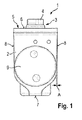
- Figure 1 shows a concealed door operator according to an exemplary embodiment of the present invention.
- the concealed door operator 1 comprises a housing 2, in which an operating unit 3 is provided.
- the operating unit 3 is adapted to operate a door equipped with the concealed door operator 1.
- the concealed door operator 1 can be provided within a cavity 13 of a door leaf 12.
- the operating unit 3 For operating the door, i.e. for opening or closing the door, the operating unit 3 comprises a square pinion 4, which is the only part of the operating unit 3 being accessible from outside the housing 2.
- the square pinion 4 can be connected to a level arm which is supported on a wall.
- the square pinion 4 When opening or closing the door, the square pinion 4 is rotated and a load is applied to the operating unit 3.
- This energy is stored within the operating unit 3 and can be used for operating the door.
- energy is stored within the operating unit 3 when opening the door such that the concealed door closer 1 can use the stored energy for closing the door.
- the housing 2 of the concealed door operator 1 comprises a top face 6, an opposing bottom face 7, and side faces 8.
- mounting features 5 are provided on the top face 6, mounting features 5 are provided.
- the mounting features 5 comprise flanges and through holes for mounting the concealed door operator 1 on a door leaf 12 or a wall or a floor.
- the concealed door operator 1 is installed within a cavity 13 of the door leaf 12, while the flanges of the mounting features 5 are disposed on surfaces outside the cavity 13. Mounting screws can be used for fixing the flanges via the through holes of the mounting features 5.
- the housing 2 is preferably a single cast piece, which can be made from aluminum or iron.
- the housing 2 is very simple to manufacture. Since the mounting features 5 are integrally formed with the housing 2, only a single cast piece has to be manufactured.
- the housing 2 has a generally prismatic shape.
- the mounting features 5, in particular the flanges, are provided on base faces of the prism. This results in a narrow mounting space required for installation of the concealed door operator 1.
- the housing comprises an opening for inserting at least parts of the operating unit 3.
- the opening is covered by an end cap 9 which also serves as support for the operating unit 3.
- the operating unit 3 is adapted to store energy when moving the door equipped with the concealed door operator 1 in one direction and is adapted to drive the door in the other direction from the stored energy. At the same time, any movement of the door is damped.
- the operating unit 3 applies pressure to the end cap 9. Therefore, the end cap is designed to withstand the pressure.
- the side faces 8 of the housing 2 are inclined.
- the side faces 8 are inclined inward such that the bottom face 7 needs to be smaller than the top face 6. Therefore, a draft angle A is present between a vertical plane and the side faces 8.
- the draft angle A is selected between 0.5 and 1.0 degree.
- the side faces 8 are inclined for two reasons: First, the draft angle A facilitates the ejection of the raw housing from the mold during production, especially in case the housing2 is produced by the pressure die casting process. Second, the inclined side faces 8 of the housing 2 function as lead-in to the cavity during installation of the concealed door operator 1. With this feature, the installer need not align accurately to insert the concealed door operator 1 into the cavity 13. The lead-in also caters for a snug fit at the top face when the concealed door operator 1 is completely installed to the door leaf 12.
- Figures 2 and 3 show two steps of installing the concealed door operator 1 into the cavity 13 of the door leaf 12.
- a first step is shown in figure 2 . It is apparent that the draft angle A functions as lead-in to the cavity 13, since the narrower dimension at the bottom face 7 provides clearance 10 for the initial engagement. After initial engagement, the concealed door closer 1 slides into the cavity 13, preferably guided by the draft.
- Figure 3 shows a second step of installing the concealed door operator 1.
- the state shown in figure 3 is when the concealed door operator 1 is completely inserted into the cavity 13.
- the dimension of the top face 6 is substantially equal to the dimension of the cavity such that an appearance of tight fit 11 is given.
- the inclined side faces 8 of the housing 2 provide both, a clearance 10 at the beginning of the installation process and a tight fit 11 at the end of the installation process.
- the concealed door operator 1 is low in cost and simple to install.
Landscapes
- Power-Operated Mechanisms For Wings (AREA)
- Securing Of Glass Panes Or The Like (AREA)
Abstract
Description
- The present invention regards concealed door operators. Such door operators are used for providing an opening or closing force to a door.
- In general, concealed door operators are well-known from the prior art. Concealed door operators are hidden within a door leaf or a floor or a wall, such that no visible unit needs to be provided on the door. In case of installation within a cavity of a door leaf, the width of the cavity is limited by the thickness of the door leaf. For maximum residual strength, of the door, the width of the cavity should be just wide enough to accommodate the door closer. This leaves very little clearance between the outer wall of the concealed door operator and the inner wall of the door cavity. The installer has to take extra care to align the housing to the cavity. If the clearance is tight, additional effort is required to press the closer into position within the cavity.
- It is an object underlying the present invention to provide a low-maintenance concealed door operator which is simple to manufacture and install.
- The solution of this object is achieved by the features of
claim 1. Therefore, the object is solved by a concealed door operator comprising an operating unit and a housing. The housing comprises a top face and an opposing bottom face. Further, the housing comprises at least one side face between the bottom face and the top face. The operating unit comprises a square pinion protruding from the top face and allowing transmittal of torque from or to the operation unit. Further, the operating unit is provided within the housing. In a preferred embodiment, the whole operating unit is provided within the housing with the square pinion being the only part of the operating unit which is accessible from outside the housing. At least one side face is inclined such that the bottom face is smaller than the top face. In particular, said at least one side face is angulated inward such that an angle between a vertical plate and the side face remains. The inclination is preferably selected between 0.2 and 1.5 degrees, in particular between 0.5 and 1.0 degrees. Due to the inclination of said side face, the maximum dimensions of the bottom face are smaller than the dimensions of the top face. However, the bottom face could be smaller than caused by the inclination by providing a step in said side face. Such a design provides the best capability of installing the concealed door operator. Since the concealed door operator has to be provided within a cavity of a door leaf, a floor or a wall, the inclination of the side face provides a lead-in to the cavity. - The dependent claims comprise advantageous embodiments of the present invention.
- In a preferred embodiment, the concealed door operator comprises at least two opposing side faces, wherein the two opposing side faces are inclined in an opposite manner. In particular, the opposing side faces are both inclined inward. As described before, the dimensions of the bottom face have to be smaller than the dimensions of the top face due to the inclination. Preferably, the inclined side faces are symmetrically.
- The concealed door operator is preferably characterized in that the housing is a cast housing. The cast housing can be provided with stiffening means or enhanced wall sections. Further, any cast housing is simple to manufacture and low in cost. Nevertheless, the cast housing is designed to provide maximum durability during the lifecycle of the concealed door operator. Due to the inclination of the side face, there is a draft angle to facilitate the ejection of the raw housing from the mold during production, for example by the pressure die casting process.
- In another preferred embodiment, the top face comprises mounting features for mounting the concealed door operator within a door leaf or a floor or a wall. The mounting features can be flanges or boreholes for mounting the concealed door operator. In particular, the mounting features are integrally mounted with the housing.
- In particular, the housing has a prismatic shape, wherein the flanges are provided on base faces of the prism. Such a design minimizes the room required for mounting the concealed door operator. The concealed door operator can therefore be installed into door leafs having a very narrow width.
- The housing preferably has a prismatic shape, while the inclined side face is a face other than the base faces. With both faces inclined, the above mentioned advantages regarding lead-in and ejection from the mold are further enhanced.
- The concealed door operator further preferably comprises a cover plate. In order to save material, the housing preferably comprises a cavity resulting in a cutout of the top face. The cavity is covered by said cover plate, wherein the cover plate is fixed only to the housing. In particular, the cover plate is smaller than the top face such that the top face functions as frame for the cover plate.
- In a preferred embodiment of the concealed door operator, the operating unit is a door closing unit. Therefore, the door can be opened manually and is closed by the concealed door operator. Since the door operator is concealed, there is no visible unit provided on the door such that an esthetic appeal is maintained.
- Preferably, the operating unit comprises an operating piston and a damping piston. Both, the operating piston and the damping piston are engaged with a pinion cam for transforming the longitudinal movement of the pistons into a rotational movement of the pinion cam. With such a design, the concealed door operator can be installed in any door independent from the opening direction of the door. The pinion cam can be rotated clockwise or counterclockwise while in both cases load is provided to the operating unit.
- In another preferred embodiment, the operating unit also comprises an operating piston and a damping piston. The operating piston and the damping piston are connected to a rack with a pinion engaged with the rack for transforming the longitudinal movement of the pistons and the rack into a rotational movement of the pinion. This design allows an installation of the concealed door operator only in doors having a predetermined opening direction. Therefore, the concealed door operator is preferably provided in two versions, in the one version the pinion needs to be rotated clockwise for providing load to the operating unit, in the other version the pinion needs to be rotated counterclockwise for providing load to the operating unit.
- The housing particularly comprises an opening for removing and/or inserting at least parts of the operating unit. The opening is preferably covered by an end cap. The end cap is designed to withstand loads applied by the operating unit when moving the door. Further, the housing comprises a reinforced wall section around the opening. This is to enhance the durability of the housing to withstand the pressure loads applied to the end cap. This optimal design with selective stiffness enhancing integrally incorporated to the housing minimizes part and material usage while enhancing the stability and durability of the concealed door operator.
- In the following, preferred exemplary embodiments of the invention are explained with reference to the drawings. In the drawings:
- Fig. 1
- is a schematic drawing showing an exemplary embodiment of the concealed door operator according to the invention.
- Fig. 2
- is a schematic drawing showing a first step of installing the concealed door operator of
figure 1 within a door leaf. - Fig. 3
- is a schematic drawing showing a second step of installing the concealed door operator of
figure 2 within a door leaf. -
Figure 1 shows a concealed door operator according to an exemplary embodiment of the present invention. - The
concealed door operator 1 comprises ahousing 2, in which an operating unit 3 is provided. The operating unit 3 is adapted to operate a door equipped with theconcealed door operator 1. In particular, theconcealed door operator 1 can be provided within acavity 13 of adoor leaf 12. - For operating the door, i.e. for opening or closing the door, the operating unit 3 comprises a square pinion 4, which is the only part of the operating unit 3 being accessible from outside the
housing 2. The square pinion 4 can be connected to a level arm which is supported on a wall. When opening or closing the door, the square pinion 4 is rotated and a load is applied to the operating unit 3. This energy is stored within the operating unit 3 and can be used for operating the door. For example, energy is stored within the operating unit 3 when opening the door such that theconcealed door closer 1 can use the stored energy for closing the door. - The
housing 2 of theconcealed door operator 1 comprises atop face 6, an opposingbottom face 7, and side faces 8. On thetop face 6, mountingfeatures 5 are provided. The mounting features 5 comprise flanges and through holes for mounting theconcealed door operator 1 on adoor leaf 12 or a wall or a floor. In one embodiment, theconcealed door operator 1 is installed within acavity 13 of thedoor leaf 12, while the flanges of the mounting features 5 are disposed on surfaces outside thecavity 13. Mounting screws can be used for fixing the flanges via the through holes of the mounting features 5. Thehousing 2 is preferably a single cast piece, which can be made from aluminum or iron. - It can be seen from the figures and the above explanation that the
housing 2 is very simple to manufacture. Since the mounting features 5 are integrally formed with thehousing 2, only a single cast piece has to be manufactured. - The
housing 2 according to the exemplary embodiment has a generally prismatic shape. The mounting features 5, in particular the flanges, are provided on base faces of the prism. This results in a narrow mounting space required for installation of theconcealed door operator 1. - Further, the housing comprises an opening for inserting at least parts of the operating unit 3. The opening is covered by an
end cap 9 which also serves as support for the operating unit 3. The operating unit 3 is adapted to store energy when moving the door equipped with theconcealed door operator 1 in one direction and is adapted to drive the door in the other direction from the stored energy. At the same time, any movement of the door is damped. During operation, the operating unit 3 applies pressure to theend cap 9. Therefore, the end cap is designed to withstand the pressure. - The side faces 8 of the
housing 2 are inclined. In particularly, the side faces 8 are inclined inward such that thebottom face 7 needs to be smaller than thetop face 6. Therefore, a draft angle A is present between a vertical plane and the side faces 8. The draft angle A is selected between 0.5 and 1.0 degree. - The side faces 8 are inclined for two reasons: First, the draft angle A facilitates the ejection of the raw housing from the mold during production, especially in case the housing2 is produced by the pressure die casting process. Second, the inclined side faces 8 of the
housing 2 function as lead-in to the cavity during installation of theconcealed door operator 1. With this feature, the installer need not align accurately to insert theconcealed door operator 1 into thecavity 13. The lead-in also caters for a snug fit at the top face when theconcealed door operator 1 is completely installed to thedoor leaf 12. -
Figures 2 and 3 show two steps of installing theconcealed door operator 1 into thecavity 13 of thedoor leaf 12. A first step is shown infigure 2 . It is apparent that the draft angle A functions as lead-in to thecavity 13, since the narrower dimension at thebottom face 7 providesclearance 10 for the initial engagement. After initial engagement, theconcealed door closer 1 slides into thecavity 13, preferably guided by the draft. -
Figure 3 shows a second step of installing theconcealed door operator 1. The state shown infigure 3 is when theconcealed door operator 1 is completely inserted into thecavity 13. The dimension of thetop face 6 is substantially equal to the dimension of the cavity such that an appearance oftight fit 11 is given. Hence, the inclined side faces 8 of thehousing 2 provide both, aclearance 10 at the beginning of the installation process and atight fit 11 at the end of the installation process. - It can be seen from the above that the exemplary embodiments of the
concealed door operator 1 that the invention provides several advantages during installation. Therefore, theconcealed door operator 1 is low in cost and simple to install. -
- 1
- concealed door operator
- 2
- housing
- 3
- operating unit
- 4
- square pinion
- 5
- mounting feature
- 6
- top face
- 7
- bottom face
- 8
- side face
- 9
- end cap
- 10
- clearance
- 11
- snug fit
- 12
- door leaf
- 13
- cavity
- A
- draft angle
Claims (10)
- Concealed door operator (1), comprising- an operating unit (3) having a square pinion (4) allowing transmittal of forces to or from the operating unit (3), and- a housing (2), having a top face (6), an opposing bottom face (7), and at least one side face (8) between the top face (6) and the bottom face (7),- wherein operating unit (3) is provided within the housing (2),- wherein said square pinion (4) protrudes from the top face (6), and- wherein at least one side face (8) is inclined such that the bottom face (7) is smaller than the top face (6).
- Concealed door operator (1) according to claim 1, characterized by at least two opposing side faces (8), wherein the two opposing side faces (8) are inclined in an opposite manner.
- Concealed door operator (1) according to claim 1 or 2, characterized in that the housing (2) is a cast housing.
- Concealed door operator (1) according to one of claims 1 to 3, characterized in that the top face (6) comprises mounting features (5) for mounting the concealed door operator (1) within a door leaf (12) or a floor or a wall.
- Concealed door operator (1) according to claim 4, characterized in that the housing (2) has a prismatic shape and the mounting features (5) are provided on base faces of the prism.
- Concealed door operator (1) according to one of claims 1 to 5, characterized in that the housing (2) has a prismatic shape and the inclined side face (8) is a face other than the base faces.
- Concealed door operator (1) according to one of the claims 1 to 6, characterized by a cover plate, wherein the cover plate is fixed only to the housing (2).
- Concealed door operator (1) according to one of the claims 1 to 7, characterized in that the operating unit (3) is a door closing unit.
- Concealed door operator (1) according to one of the claims 1 to 8, characterized in that the operating unit (3) comprises an operating piston and a damping piston, wherein the operating piston and the damping piston are engaged with a pinion cam for transforming the longitudinal movement of the pistons into a rotational movement of the pinion cam.
- Concealed door operator (1) according to one of the claims 1 to 9, characterized in that the operating unit (3) comprises an operating piston and a damping piston, wherein the operating piston and the damping piston are connected to a rack with a pinion engaged with the rack for transforming the longitudinal movement of the pistons and the rack into a rotational movement of the pinion.
Priority Applications (3)
| Application Number | Priority Date | Filing Date | Title |
|---|---|---|---|
| EP14003054.5A EP2993293A1 (en) | 2014-09-04 | 2014-09-04 | Concealed door operator |
| CN201420688678.9U CN204677035U (en) | 2014-09-04 | 2014-10-14 | Hidden door controller |
| CN201410654486.0A CN105421927A (en) | 2014-09-04 | 2014-10-14 | Concealed door operator |
Applications Claiming Priority (1)
| Application Number | Priority Date | Filing Date | Title |
|---|---|---|---|
| EP14003054.5A EP2993293A1 (en) | 2014-09-04 | 2014-09-04 | Concealed door operator |
Publications (1)
| Publication Number | Publication Date |
|---|---|
| EP2993293A1 true EP2993293A1 (en) | 2016-03-09 |
Family
ID=52100967
Family Applications (1)
| Application Number | Title | Priority Date | Filing Date |
|---|---|---|---|
| EP14003054.5A Withdrawn EP2993293A1 (en) | 2014-09-04 | 2014-09-04 | Concealed door operator |
Country Status (2)
| Country | Link |
|---|---|
| EP (1) | EP2993293A1 (en) |
| CN (2) | CN204677035U (en) |
Citations (3)
| Publication number | Priority date | Publication date | Assignee | Title |
|---|---|---|---|---|
| US799342A (en) * | 1904-08-06 | 1905-09-12 | Yale & Towne Mfg Co | Combined floor-hinge, door check and closer. |
| EP1431497A2 (en) * | 2002-12-19 | 2004-06-23 | GEZE GmbH | Free running device for a wing control of a door or window |
| EP2345788A2 (en) * | 2010-01-19 | 2011-07-20 | Taiwan Daedalus Door Control, Co., Ltd. | Door closer kit for double swing door |
-
2014
- 2014-09-04 EP EP14003054.5A patent/EP2993293A1/en not_active Withdrawn
- 2014-10-14 CN CN201420688678.9U patent/CN204677035U/en not_active Expired - Lifetime
- 2014-10-14 CN CN201410654486.0A patent/CN105421927A/en active Pending
Patent Citations (3)
| Publication number | Priority date | Publication date | Assignee | Title |
|---|---|---|---|---|
| US799342A (en) * | 1904-08-06 | 1905-09-12 | Yale & Towne Mfg Co | Combined floor-hinge, door check and closer. |
| EP1431497A2 (en) * | 2002-12-19 | 2004-06-23 | GEZE GmbH | Free running device for a wing control of a door or window |
| EP2345788A2 (en) * | 2010-01-19 | 2011-07-20 | Taiwan Daedalus Door Control, Co., Ltd. | Door closer kit for double swing door |
Also Published As
| Publication number | Publication date |
|---|---|
| CN105421927A (en) | 2016-03-23 |
| CN204677035U (en) | 2015-09-30 |
Similar Documents
| Publication | Publication Date | Title |
|---|---|---|
| US7669285B2 (en) | Damping device for furniture hinges | |
| JP4084330B2 (en) | Braking damping adapter | |
| KR20140027271A (en) | Fastening assembly for a built-in refrigerator on a side wall of a furniture body | |
| US20130219813A1 (en) | Hinge reinforced frame assembly | |
| KR102055903B1 (en) | Motor vehicle door lock | |
| EP4135492A1 (en) | Electronic device and method of assembling the same | |
| EP2278104A1 (en) | Snap hinge with damper and fixing plate for snap hinge | |
| JP2016089546A (en) | Sliding door for locking device | |
| KR101415378B1 (en) | Door hinge for automobile | |
| US9725931B2 (en) | Actuating unit for a motor vehicle lock and corresponding method of production | |
| US9109388B2 (en) | Door coordinator accessory mounting bracket | |
| EP3153800A1 (en) | Refrigerator | |
| EP2993294A1 (en) | Concealed door operator | |
| EP2993292A1 (en) | Concealed door operator | |
| EP2993295A1 (en) | Concealed door operator | |
| CN204677035U (en) | Hidden door controller | |
| US9650820B2 (en) | Structural arrangement in pneumatic floor spring | |
| JP7297297B2 (en) | Upper guide for sliding door and sliding door structure | |
| KR100770425B1 (en) | Damping device for furniture hinge | |
| JP2010065479A (en) | Door mounting structure for mirror cabinet | |
| JP6956441B2 (en) | Vehicle backdoor structure | |
| CN105082951A (en) | Frame part consisting of vehicle door window, system of composite part, and composite part | |
| US12392173B2 (en) | Lock comprising a slider flush relative to a sole plate provided with a recess for receiving a translation stop preventing the slider from translating | |
| JP2005118125A (en) | Locking apparatus for game machine | |
| US20070186376A1 (en) | Floor spring |
Legal Events
| Date | Code | Title | Description |
|---|---|---|---|
| PUAI | Public reference made under article 153(3) epc to a published international application that has entered the european phase |
Free format text: ORIGINAL CODE: 0009012 |
|
| AK | Designated contracting states |
Kind code of ref document: A1 Designated state(s): AL AT BE BG CH CY CZ DE DK EE ES FI FR GB GR HR HU IE IS IT LI LT LU LV MC MK MT NL NO PL PT RO RS SE SI SK SM TR |
|
| AX | Request for extension of the european patent |
Extension state: BA ME |
|
| 17P | Request for examination filed |
Effective date: 20160909 |
|
| RBV | Designated contracting states (corrected) |
Designated state(s): AL AT BE BG CH CY CZ DE DK EE ES FI FR GB GR HR HU IE IS IT LI LT LU LV MC MK MT NL NO PL PT RO RS SE SI SK SM TR |
|
| STAA | Information on the status of an ep patent application or granted ep patent |
Free format text: STATUS: REQUEST FOR EXAMINATION WAS MADE |
|
| STAA | Information on the status of an ep patent application or granted ep patent |
Free format text: STATUS: THE APPLICATION IS DEEMED TO BE WITHDRAWN |
|
| 18D | Application deemed to be withdrawn |
Effective date: 20160910 |