EP2993120A1 - Ship propulsion arrangement - Google Patents
Ship propulsion arrangement Download PDFInfo
- Publication number
- EP2993120A1 EP2993120A1 EP14183406.9A EP14183406A EP2993120A1 EP 2993120 A1 EP2993120 A1 EP 2993120A1 EP 14183406 A EP14183406 A EP 14183406A EP 2993120 A1 EP2993120 A1 EP 2993120A1
- Authority
- EP
- European Patent Office
- Prior art keywords
- blade
- blades
- propulsion arrangement
- flanges
- ship propulsion
- Prior art date
- Legal status (The legal status is an assumption and is not a legal conclusion. Google has not performed a legal analysis and makes no representation as to the accuracy of the status listed.)
- Withdrawn
Links
- 238000005266 casting Methods 0.000 claims description 2
- 230000003247 decreasing effect Effects 0.000 description 1
- 230000001419 dependent effect Effects 0.000 description 1
Images
Classifications
-
- B—PERFORMING OPERATIONS; TRANSPORTING
- B63—SHIPS OR OTHER WATERBORNE VESSELS; RELATED EQUIPMENT
- B63H—MARINE PROPULSION OR STEERING
- B63H1/00—Propulsive elements directly acting on water
- B63H1/02—Propulsive elements directly acting on water of rotary type
- B63H1/12—Propulsive elements directly acting on water of rotary type with rotation axis substantially in propulsive direction
- B63H1/14—Propellers
- B63H1/20—Hubs; Blade connections
Definitions
- the present invention relates to a ship propulsion arrangement.
- Propellers of certain ships such as ice-going vessels, need to withstand very high loads whereby the blades are typically very thick.
- propulsion drive train including, e.g., propeller shaft, bearings and housing, needs to withstand a breakage load of one propeller blade.
- One option to reduce blade breakage load is to increase the number of blades, which results narrower and possibly thinner individual blades.
- blades Often it is desired, or required by flag authorities, that the blades shall be replaceable.
- the blades are attached to a propeller hub by means of a so called blade flange.
- the attachment of a greater number of blade flanges to a propeller hub to meet the replaceability and reduction of blade thickness requirements is strength-wise often not possible.
- An object of the present invention is to provide a propulsion arrangement so as to alleviate the above disadvantages.
- the object of the invention is achieved with a propulsion arrangement which is defined in the independent claim.
- a ship propulsion arrangement comprising a propeller hub, and to the propeller hub detachably attachable blade flanges each carrying an integral blade. At least one of the blade flanges carries at least two, to the blade flange, integrally formed blades.
- number of blade flanges is two, three or four, preferably two or three, whereby each blade flange covers a great portion of the hub circumference.
- each blade flange carries two blades.
- the propulsion arrangement comprises three blade flanges, whereby the number of blades is six. In another embodiment, the number of blade flanges is four.
- the blades of the same blade flange are arranged overlappingly when seen from an end of the propeller hub. In this way the efficiency or the strength of the propeller hub may be increased.
- the propeller is attached to an azimuthing propulsion unit.
- the propeller is attached to an azimuthing podded propulsion unit.
- the propeller is attached to a pulling propulsion unit.
- the embodiments relate to a propeller arrangement of a ship.
- the ship is an ice-going vessel such as an ice-breaker.
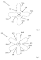
- Figure 1 shows a prior art propeller arrangement seen from the end that is along the rotation axis of the propeller. In the middle of the propeller arrangement there is a hub 102 to which the blade flanges are attached to.
- each blade flange in Figure 1 there are four blade flanges 104 to 110 each carrying a respective blade 104A to 110A.
- the blades are integrally formed to the blade flange by casting so that they form an integral inseparable blade flange unit.
- each flange covers about 90 degrees of a circumference of the hub.
- the problem with using more flanges, eg. six flanges each covering about 60 degrees of the circumference, would be that the flanges cannot adequately and sufficiently be attached to the hub, for example, with bolts, to withstand the high loads caused by, for example, ice blocks hitting the blades.
- FIG. 2 shows an embodiment of the invention.
- the blade flange 204 carries two blades 204A, 204B.
- the blade flanges can be attached to the hub very well. That is, there is sufficiently space on the blade flange to receive a plurality of bolts for fastening the flange to the hub. Also the share of the blade flange of the circumference of the hub is so great that the bolt openings can be distributed over the flange area to obtain maximal fastening of the flange to the hub.
- the number of blades can be increased compared to prior solutions, whereby their dimensions, for example blade root section thickness and chord length, can also be reduced and therefore the blade breakage load is decreased. This can lead to lower dimensioning load of the whole propulsion drive train and therefore possible more cost and/or efficiency optimised propulsion.
- the replaceability requirements of blades are met also by this solution of the invention.
- those blades that share same flange may be manufactured to overlap each other, when looking from behind of the propeller and/or from the blade root sections.
- the blades are at the same position along the rotation axis of the propeller unit. That is, the blades are in the same plane with each other. The blades may then be arranged non-overlappingly to each other.
- Figure 2 shows one embodiment of the invention, where the propeller has altogether six blades in three blade flanges. Other embodiments are also possible. There may, for instance, be eight blades in four flanges or four blades in two flanges. The number of blades in flanges can also vary, such that there may be five blades in three flanges where the flanges are of equal size. In a still further embodiment, at least one of the blade flanges may carry three blades.
Landscapes
- Chemical & Material Sciences (AREA)
- Engineering & Computer Science (AREA)
- Combustion & Propulsion (AREA)
- Mechanical Engineering (AREA)
- Ocean & Marine Engineering (AREA)
- Structures Of Non-Positive Displacement Pumps (AREA)
Abstract
A ship propulsion arrangement, comprising a propeller hub (202), and to the propeller hub detachably attachable blade flanges (204, 206, 208) each carrying an integral blade. At least one of the blade flanges carries at least two, to the blade flange, integrally formed blades (204A, 204B).
Description
- The present invention relates to a ship propulsion arrangement.
- Propellers of certain ships, such as ice-going vessels, need to withstand very high loads whereby the blades are typically very thick. Often it is required by flag authorities, for example, by the means of ship classification rules for ice-going vessels, that propulsion drive train including, e.g., propeller shaft, bearings and housing, needs to withstand a breakage load of one propeller blade. One option to reduce blade breakage load is to increase the number of blades, which results narrower and possibly thinner individual blades.
- Often it is desired, or required by flag authorities, that the blades shall be replaceable. The blades are attached to a propeller hub by means of a so called blade flange. The attachment of a greater number of blade flanges to a propeller hub to meet the replaceability and reduction of blade thickness requirements is strength-wise often not possible.
- An improved solution is thus called for.
- An object of the present invention is to provide a propulsion arrangement so as to alleviate the above disadvantages. The object of the invention is achieved with a propulsion arrangement which is defined in the independent claim. Some embodiments are disclosed in the dependent claims.
- In an aspect there is provided a ship propulsion arrangement, comprising a propeller hub, and to the propeller hub detachably attachable blade flanges each carrying an integral blade. At least one of the blade flanges carries at least two, to the blade flange, integrally formed blades. When the number of blades on a blade flange and the propeller is increased, the dimensions and blade breakage load of each single blade are reduced, without compromising the fastening of blade flanges to a propeller hub.
- In the embodiments, number of blade flanges is two, three or four, preferably two or three, whereby each blade flange covers a great portion of the hub circumference.
- In an embodiment, each blade flange carries two blades. In an embodiment, the propulsion arrangement comprises three blade flanges, whereby the number of blades is six. In another embodiment, the number of blade flanges is four.
- In an embodiment, the blades of the same blade flange are arranged overlappingly when seen from an end of the propeller hub. In this way the efficiency or the strength of the propeller hub may be increased.
- In an embodiment, the propeller is attached to an azimuthing propulsion unit.
- In an embodiment, the propeller is attached to an azimuthing podded propulsion unit.
- In an embodiment, the propeller is attached to a pulling propulsion unit.
- In the following, the invention will be described in greater detail by means of some embodiments with reference to the accompanying drawings, in which
-
Figure 1 shows a prior art propeller; -
Figure 2 shows an embodiment of a propeller according to the invention. - The embodiments relate to a propeller arrangement of a ship. In some embodiments, the ship is an ice-going vessel such as an ice-breaker.
-
Figure 1 shows a prior art propeller arrangement seen from the end that is along the rotation axis of the propeller. In the middle of the propeller arrangement there is ahub 102 to which the blade flanges are attached to. - In
Figure 1 there are fourblade flanges 104 to 110 each carrying arespective blade 104A to 110A. The blades are integrally formed to the blade flange by casting so that they form an integral inseparable blade flange unit. As there are four blade flanges, each flange covers about 90 degrees of a circumference of the hub. The problem with using more flanges, eg. six flanges each covering about 60 degrees of the circumference, would be that the flanges cannot adequately and sufficiently be attached to the hub, for example, with bolts, to withstand the high loads caused by, for example, ice blocks hitting the blades. -
Figure 2 shows an embodiment of the invention. In this embodiment, there are only threeblade flanges 204 to 208, and each of the flanges carries two blades. For example, theblade flange 204 carries twoblades - In this way, multiple goals are achieved. The blade flanges can be attached to the hub very well. That is, there is sufficiently space on the blade flange to receive a plurality of bolts for fastening the flange to the hub. Also the share of the blade flange of the circumference of the hub is so great that the bolt openings can be distributed over the flange area to obtain maximal fastening of the flange to the hub. The number of blades can be increased compared to prior solutions, whereby their dimensions, for example blade root section thickness and chord length, can also be reduced and therefore the blade breakage load is decreased. This can lead to lower dimensioning load of the whole propulsion drive train and therefore possible more cost and/or efficiency optimised propulsion. The replaceability requirements of blades are met also by this solution of the invention.
- If desired, for example, from the efficiency or strength point of view in such case that the power density of the propeller is high and thus large blade area ratio is required, those blades that share same flange may be manufactured to overlap each other, when looking from behind of the propeller and/or from the blade root sections.
- In another embodiment, the blades are at the same position along the rotation axis of the propeller unit. That is, the blades are in the same plane with each other. The blades may then be arranged non-overlappingly to each other.
-
Figure 2 shows one embodiment of the invention, where the propeller has altogether six blades in three blade flanges. Other embodiments are also possible. There may, for instance, be eight blades in four flanges or four blades in two flanges. The number of blades in flanges can also vary, such that there may be five blades in three flanges where the flanges are of equal size. In a still further embodiment, at least one of the blade flanges may carry three blades. - The most optimal solution is, however, the one shown in
Figure 2 , because six blades in three flanges optimises the strength requirements of fastening the flanges to the hub. The number of blades being six is also sufficient for it being possible to reduce the size of the blades still meeting the strength requirements of the blades. - It will be obvious to a person skilled in the art that, as the technology advances, the inventive concept can be implemented in various ways. The invention and its embodiments are not limited to the examples described above but may vary within the scope of the claims.
Claims (11)
1. A ship propulsion arrangement, comprising a propeller hub (202), and to the propeller hub detachably attachable blade flanges (204, 206, 208) each carrying an integral blade, characterized in that at least one of the blade flanges (204) carries at least two, to the blade flange, integrally formed blades (204A, 204B).
2. A ship propulsion arrangement according to claim 1, character-i z e d in that the ship is an ice-going vessel.
3. A ship propulsion arrangement according to any preceding claim, characterized in that each of the blade flanges (204, 206, 208) carries two integral blades (204A, 204B, 206A, 206B, 208A, 208B).
4. A ship propulsion arrangement according to any preceding claim, characterized in that the blades (204A, 204B) are formed integrally to the blade flange (204) by casting.
5. A ship propulsion arrangement according to any preceding claim, characterized in that the propulsion arrangement comprises three blade flanges (204, 206, 208).
6. A ship propulsion arrangement according to any preceding claim, characterized in that the propulsion arrangement comprises four blade flanges.
7. A ship propulsion arrangement according to any preceding claim, characterized in that the blade flanges (204, 206, 208) are attachable to the propeller hub (202) by bolting.
8. A ship propulsion arrangement according to any preceding claim, characterized in that the blades of the same blade flange are arranged overlappingly when seen from an end of the propeller hub.
10. A ship propulsion arrangement according to any preceding claim, characterized in that the propeller hub (202) is attached to an azimuthing propulsion unit.
11. A ship propulsion arrangement according to any preceding claim, characterized in that the propeller hub (202) is attached to an azimuthing podded propulsion unit.
12. A ship propulsion arrangement according to any preceding claim, characterized in that the propeller hub (202) is attached to a pulling propulsion unit.
Priority Applications (1)
| Application Number | Priority Date | Filing Date | Title |
|---|---|---|---|
| EP14183406.9A EP2993120A1 (en) | 2014-09-03 | 2014-09-03 | Ship propulsion arrangement |
Applications Claiming Priority (1)
| Application Number | Priority Date | Filing Date | Title |
|---|---|---|---|
| EP14183406.9A EP2993120A1 (en) | 2014-09-03 | 2014-09-03 | Ship propulsion arrangement |
Publications (1)
| Publication Number | Publication Date |
|---|---|
| EP2993120A1 true EP2993120A1 (en) | 2016-03-09 |
Family
ID=51483265
Family Applications (1)
| Application Number | Title | Priority Date | Filing Date |
|---|---|---|---|
| EP14183406.9A Withdrawn EP2993120A1 (en) | 2014-09-03 | 2014-09-03 | Ship propulsion arrangement |
Country Status (1)
| Country | Link |
|---|---|
| EP (1) | EP2993120A1 (en) |
Cited By (1)
| Publication number | Priority date | Publication date | Assignee | Title |
|---|---|---|---|---|
| RU2708696C1 (en) * | 2019-04-01 | 2019-12-11 | Общество С Ограниченной Ответственностью "Прикладной Инженерный И Учебный Центр "Сапфир" | Screw propeller of screw-steering column of water vessel and screw-steering column with said screw propeller |
Citations (4)
| Publication number | Priority date | Publication date | Assignee | Title |
|---|---|---|---|---|
| US3575530A (en) * | 1968-09-05 | 1971-04-20 | Clifton W Hall | Variable pitch propeller |
| US4566855A (en) * | 1981-08-28 | 1986-01-28 | Costabile John J | Shock absorbing clutch assembly for marine propeller |
| WO2012008901A1 (en) * | 2010-07-12 | 2012-01-19 | Rolls-Royce Aktiebolag | A propulsion unit for a marine vessel and a marine vessel having a propulsion unit |
| EP2497709A1 (en) * | 2009-11-05 | 2012-09-12 | Pablo Alfonso Gonzalez Abal | Vessel propulsion device |
-
2014
- 2014-09-03 EP EP14183406.9A patent/EP2993120A1/en not_active Withdrawn
Patent Citations (4)
| Publication number | Priority date | Publication date | Assignee | Title |
|---|---|---|---|---|
| US3575530A (en) * | 1968-09-05 | 1971-04-20 | Clifton W Hall | Variable pitch propeller |
| US4566855A (en) * | 1981-08-28 | 1986-01-28 | Costabile John J | Shock absorbing clutch assembly for marine propeller |
| EP2497709A1 (en) * | 2009-11-05 | 2012-09-12 | Pablo Alfonso Gonzalez Abal | Vessel propulsion device |
| WO2012008901A1 (en) * | 2010-07-12 | 2012-01-19 | Rolls-Royce Aktiebolag | A propulsion unit for a marine vessel and a marine vessel having a propulsion unit |
Cited By (2)
| Publication number | Priority date | Publication date | Assignee | Title |
|---|---|---|---|---|
| RU2708696C1 (en) * | 2019-04-01 | 2019-12-11 | Общество С Ограниченной Ответственностью "Прикладной Инженерный И Учебный Центр "Сапфир" | Screw propeller of screw-steering column of water vessel and screw-steering column with said screw propeller |
| EP3718874A1 (en) | 2019-04-01 | 2020-10-07 | Aetc Sapphire | Screw propeller of a pod drive of a vessel and pod drive comprising said screw propeller |
Similar Documents
| Publication | Publication Date | Title |
|---|---|---|
| KR101359828B1 (en) | Ship comprising magnus rotors | |
| EP2858893B2 (en) | Ship propeller | |
| EP2338783B1 (en) | Twin skeg ship | |
| US9816556B2 (en) | Rolling bearing, notably for ship's propeller or for wind turbine | |
| US7025642B1 (en) | Boat propeller | |
| US20190193825A1 (en) | Segmented rigid sail | |
| Atlar et al. | A multi-purpose marine science and technology research vessel for full-scale observations and measurements | |
| ES2616088T3 (en) | Boat with opening for the withdrawal of a power supply system | |
| US9021970B2 (en) | Propulsion device and ship using the same | |
| EP0867361A2 (en) | Nautical propulsor with ducted rotor propeller | |
| US10569851B1 (en) | Dual blade assembly propeller | |
| US2306840A (en) | Propeller system | |
| US10677318B2 (en) | Gearbox for a dredging vessel | |
| US33459A (en) | Improved marine propeller | |
| CN115416830A (en) | Propeller device for icebreaking ship | |
| WO2015135079A1 (en) | Shallow draft propeller nozzle | |
| FI130447B (en) | Marine propeller | |
| RU183212U1 (en) | Rotary ship | |
| JP2008149746A (en) | Contra-rotating propeller device for ship | |
| US1304287A (en) | Best available copy | |
| KR20110083423A (en) | Propellers and ships containing them | |
| EP2708462A1 (en) | Propulsion device for a floating vessel | |
| KR20150035640A (en) | Propulsion apparatus for vessel | |
| RU31766U1 (en) | ROW SCREW HYDROTURBINE | |
| Altosole et al. | Performance analysis of a motor-sailing propulsion system for control design purposes |
Legal Events
| Date | Code | Title | Description |
|---|---|---|---|
| PUAI | Public reference made under article 153(3) epc to a published international application that has entered the european phase |
Free format text: ORIGINAL CODE: 0009012 |
|
| AK | Designated contracting states |
Kind code of ref document: A1 Designated state(s): AL AT BE BG CH CY CZ DE DK EE ES FI FR GB GR HR HU IE IS IT LI LT LU LV MC MK MT NL NO PL PT RO RS SE SI SK SM TR |
|
| AX | Request for extension of the european patent |
Extension state: BA ME |
|
| STAA | Information on the status of an ep patent application or granted ep patent |
Free format text: STATUS: THE APPLICATION IS DEEMED TO BE WITHDRAWN |
|
| 18D | Application deemed to be withdrawn |
Effective date: 20160910 |