EP2993098A1 - Work vehicle, and work vehicle control method - Google Patents
Work vehicle, and work vehicle control method Download PDFInfo
- Publication number
- EP2993098A1 EP2993098A1 EP14878674.2A EP14878674A EP2993098A1 EP 2993098 A1 EP2993098 A1 EP 2993098A1 EP 14878674 A EP14878674 A EP 14878674A EP 2993098 A1 EP2993098 A1 EP 2993098A1
- Authority
- EP
- European Patent Office
- Prior art keywords
- power
- work implement
- engine
- transmission
- torque
- Prior art date
- Legal status (The legal status is an assumption and is not a legal conclusion. Google has not performed a legal analysis and makes no representation as to the accuracy of the status listed.)
- Granted
Links
- 238000000034 method Methods 0.000 title claims abstract description 22
- 230000005540 biological transmission Effects 0.000 claims abstract description 351
- 239000012530 fluid Substances 0.000 claims description 24
- 230000004044 response Effects 0.000 claims description 16
- 230000007246 mechanism Effects 0.000 description 41
- 239000003990 capacitor Substances 0.000 description 27
- 238000001514 detection method Methods 0.000 description 18
- 238000010586 diagram Methods 0.000 description 10
- 238000010521 absorption reaction Methods 0.000 description 8
- 230000006870 function Effects 0.000 description 8
- 238000006073 displacement reaction Methods 0.000 description 7
- 230000033228 biological regulation Effects 0.000 description 6
- 239000000446 fuel Substances 0.000 description 6
- 101100260051 Caenorhabditis elegans cct-1 gene Proteins 0.000 description 4
- 101100152619 Drosophila melanogaster CCT1 gene Proteins 0.000 description 4
- 230000008859 change Effects 0.000 description 4
- 238000002347 injection Methods 0.000 description 4
- 239000007924 injection Substances 0.000 description 4
- ATJFFYVFTNAWJD-UHFFFAOYSA-N Tin Chemical compound [Sn] ATJFFYVFTNAWJD-UHFFFAOYSA-N 0.000 description 3
- 230000008602 contraction Effects 0.000 description 3
- 238000001816 cooling Methods 0.000 description 3
- 230000007423 decrease Effects 0.000 description 3
- 230000005611 electricity Effects 0.000 description 3
- XDDAORKBJWWYJS-UHFFFAOYSA-N glyphosate Chemical compound OC(=O)CNCP(O)(O)=O XDDAORKBJWWYJS-UHFFFAOYSA-N 0.000 description 3
- 230000008878 coupling Effects 0.000 description 2
- 238000010168 coupling process Methods 0.000 description 2
- 238000005859 coupling reaction Methods 0.000 description 2
- 230000000694 effects Effects 0.000 description 2
- 230000007659 motor function Effects 0.000 description 2
- 230000001133 acceleration Effects 0.000 description 1
- 238000009412 basement excavation Methods 0.000 description 1
- 230000002706 hydrostatic effect Effects 0.000 description 1
- 238000005461 lubrication Methods 0.000 description 1
- 238000012986 modification Methods 0.000 description 1
- 230000004048 modification Effects 0.000 description 1
- 230000007935 neutral effect Effects 0.000 description 1
- 230000002093 peripheral effect Effects 0.000 description 1
- 238000010248 power generation Methods 0.000 description 1
- 230000009467 reduction Effects 0.000 description 1
- 230000001172 regenerating effect Effects 0.000 description 1
- 239000000243 solution Substances 0.000 description 1
Images


Classifications
-
- E—FIXED CONSTRUCTIONS
- E02—HYDRAULIC ENGINEERING; FOUNDATIONS; SOIL SHIFTING
- E02F—DREDGING; SOIL-SHIFTING
- E02F9/00—Component parts of dredgers or soil-shifting machines, not restricted to one of the kinds covered by groups E02F3/00 - E02F7/00
- E02F9/20—Drives; Control devices
- E02F9/22—Hydraulic or pneumatic drives
- E02F9/2246—Control of prime movers, e.g. depending on the hydraulic load of work tools
-
- B—PERFORMING OPERATIONS; TRANSPORTING
- B60—VEHICLES IN GENERAL
- B60K—ARRANGEMENT OR MOUNTING OF PROPULSION UNITS OR OF TRANSMISSIONS IN VEHICLES; ARRANGEMENT OR MOUNTING OF PLURAL DIVERSE PRIME-MOVERS IN VEHICLES; AUXILIARY DRIVES FOR VEHICLES; INSTRUMENTATION OR DASHBOARDS FOR VEHICLES; ARRANGEMENTS IN CONNECTION WITH COOLING, AIR INTAKE, GAS EXHAUST OR FUEL SUPPLY OF PROPULSION UNITS IN VEHICLES
- B60K6/00—Arrangement or mounting of plural diverse prime-movers for mutual or common propulsion, e.g. hybrid propulsion systems comprising electric motors and internal combustion engines ; Control systems therefor, i.e. systems controlling two or more prime movers, or controlling one of these prime movers and any of the transmission, drive or drive units Informative references: mechanical gearings with secondary electric drive F16H3/72; arrangements for handling mechanical energy structurally associated with the dynamo-electric machine H02K7/00; machines comprising structurally interrelated motor and generator parts H02K51/00; dynamo-electric machines not otherwise provided for in H02K see H02K99/00
- B60K6/20—Arrangement or mounting of plural diverse prime-movers for mutual or common propulsion, e.g. hybrid propulsion systems comprising electric motors and internal combustion engines ; Control systems therefor, i.e. systems controlling two or more prime movers, or controlling one of these prime movers and any of the transmission, drive or drive units Informative references: mechanical gearings with secondary electric drive F16H3/72; arrangements for handling mechanical energy structurally associated with the dynamo-electric machine H02K7/00; machines comprising structurally interrelated motor and generator parts H02K51/00; dynamo-electric machines not otherwise provided for in H02K see H02K99/00 the prime-movers consisting of electric motors and internal combustion engines, e.g. HEVs
- B60K6/42—Arrangement or mounting of plural diverse prime-movers for mutual or common propulsion, e.g. hybrid propulsion systems comprising electric motors and internal combustion engines ; Control systems therefor, i.e. systems controlling two or more prime movers, or controlling one of these prime movers and any of the transmission, drive or drive units Informative references: mechanical gearings with secondary electric drive F16H3/72; arrangements for handling mechanical energy structurally associated with the dynamo-electric machine H02K7/00; machines comprising structurally interrelated motor and generator parts H02K51/00; dynamo-electric machines not otherwise provided for in H02K see H02K99/00 the prime-movers consisting of electric motors and internal combustion engines, e.g. HEVs characterised by the architecture of the hybrid electric vehicle
- B60K6/44—Series-parallel type
- B60K6/445—Differential gearing distribution type
-
- B—PERFORMING OPERATIONS; TRANSPORTING
- B60—VEHICLES IN GENERAL
- B60K—ARRANGEMENT OR MOUNTING OF PROPULSION UNITS OR OF TRANSMISSIONS IN VEHICLES; ARRANGEMENT OR MOUNTING OF PLURAL DIVERSE PRIME-MOVERS IN VEHICLES; AUXILIARY DRIVES FOR VEHICLES; INSTRUMENTATION OR DASHBOARDS FOR VEHICLES; ARRANGEMENTS IN CONNECTION WITH COOLING, AIR INTAKE, GAS EXHAUST OR FUEL SUPPLY OF PROPULSION UNITS IN VEHICLES
- B60K25/00—Auxiliary drives
- B60K25/02—Auxiliary drives directly from an engine shaft
-
- B—PERFORMING OPERATIONS; TRANSPORTING
- B60—VEHICLES IN GENERAL
- B60K—ARRANGEMENT OR MOUNTING OF PROPULSION UNITS OR OF TRANSMISSIONS IN VEHICLES; ARRANGEMENT OR MOUNTING OF PLURAL DIVERSE PRIME-MOVERS IN VEHICLES; AUXILIARY DRIVES FOR VEHICLES; INSTRUMENTATION OR DASHBOARDS FOR VEHICLES; ARRANGEMENTS IN CONNECTION WITH COOLING, AIR INTAKE, GAS EXHAUST OR FUEL SUPPLY OF PROPULSION UNITS IN VEHICLES
- B60K6/00—Arrangement or mounting of plural diverse prime-movers for mutual or common propulsion, e.g. hybrid propulsion systems comprising electric motors and internal combustion engines ; Control systems therefor, i.e. systems controlling two or more prime movers, or controlling one of these prime movers and any of the transmission, drive or drive units Informative references: mechanical gearings with secondary electric drive F16H3/72; arrangements for handling mechanical energy structurally associated with the dynamo-electric machine H02K7/00; machines comprising structurally interrelated motor and generator parts H02K51/00; dynamo-electric machines not otherwise provided for in H02K see H02K99/00
- B60K6/20—Arrangement or mounting of plural diverse prime-movers for mutual or common propulsion, e.g. hybrid propulsion systems comprising electric motors and internal combustion engines ; Control systems therefor, i.e. systems controlling two or more prime movers, or controlling one of these prime movers and any of the transmission, drive or drive units Informative references: mechanical gearings with secondary electric drive F16H3/72; arrangements for handling mechanical energy structurally associated with the dynamo-electric machine H02K7/00; machines comprising structurally interrelated motor and generator parts H02K51/00; dynamo-electric machines not otherwise provided for in H02K see H02K99/00 the prime-movers consisting of electric motors and internal combustion engines, e.g. HEVs
- B60K6/22—Arrangement or mounting of plural diverse prime-movers for mutual or common propulsion, e.g. hybrid propulsion systems comprising electric motors and internal combustion engines ; Control systems therefor, i.e. systems controlling two or more prime movers, or controlling one of these prime movers and any of the transmission, drive or drive units Informative references: mechanical gearings with secondary electric drive F16H3/72; arrangements for handling mechanical energy structurally associated with the dynamo-electric machine H02K7/00; machines comprising structurally interrelated motor and generator parts H02K51/00; dynamo-electric machines not otherwise provided for in H02K see H02K99/00 the prime-movers consisting of electric motors and internal combustion engines, e.g. HEVs characterised by apparatus, components or means specially adapted for HEVs
- B60K6/28—Arrangement or mounting of plural diverse prime-movers for mutual or common propulsion, e.g. hybrid propulsion systems comprising electric motors and internal combustion engines ; Control systems therefor, i.e. systems controlling two or more prime movers, or controlling one of these prime movers and any of the transmission, drive or drive units Informative references: mechanical gearings with secondary electric drive F16H3/72; arrangements for handling mechanical energy structurally associated with the dynamo-electric machine H02K7/00; machines comprising structurally interrelated motor and generator parts H02K51/00; dynamo-electric machines not otherwise provided for in H02K see H02K99/00 the prime-movers consisting of electric motors and internal combustion engines, e.g. HEVs characterised by apparatus, components or means specially adapted for HEVs characterised by the electric energy storing means, e.g. batteries or capacitors
-
- B—PERFORMING OPERATIONS; TRANSPORTING
- B60—VEHICLES IN GENERAL
- B60K—ARRANGEMENT OR MOUNTING OF PROPULSION UNITS OR OF TRANSMISSIONS IN VEHICLES; ARRANGEMENT OR MOUNTING OF PLURAL DIVERSE PRIME-MOVERS IN VEHICLES; AUXILIARY DRIVES FOR VEHICLES; INSTRUMENTATION OR DASHBOARDS FOR VEHICLES; ARRANGEMENTS IN CONNECTION WITH COOLING, AIR INTAKE, GAS EXHAUST OR FUEL SUPPLY OF PROPULSION UNITS IN VEHICLES
- B60K6/00—Arrangement or mounting of plural diverse prime-movers for mutual or common propulsion, e.g. hybrid propulsion systems comprising electric motors and internal combustion engines ; Control systems therefor, i.e. systems controlling two or more prime movers, or controlling one of these prime movers and any of the transmission, drive or drive units Informative references: mechanical gearings with secondary electric drive F16H3/72; arrangements for handling mechanical energy structurally associated with the dynamo-electric machine H02K7/00; machines comprising structurally interrelated motor and generator parts H02K51/00; dynamo-electric machines not otherwise provided for in H02K see H02K99/00
- B60K6/20—Arrangement or mounting of plural diverse prime-movers for mutual or common propulsion, e.g. hybrid propulsion systems comprising electric motors and internal combustion engines ; Control systems therefor, i.e. systems controlling two or more prime movers, or controlling one of these prime movers and any of the transmission, drive or drive units Informative references: mechanical gearings with secondary electric drive F16H3/72; arrangements for handling mechanical energy structurally associated with the dynamo-electric machine H02K7/00; machines comprising structurally interrelated motor and generator parts H02K51/00; dynamo-electric machines not otherwise provided for in H02K see H02K99/00 the prime-movers consisting of electric motors and internal combustion engines, e.g. HEVs
- B60K6/22—Arrangement or mounting of plural diverse prime-movers for mutual or common propulsion, e.g. hybrid propulsion systems comprising electric motors and internal combustion engines ; Control systems therefor, i.e. systems controlling two or more prime movers, or controlling one of these prime movers and any of the transmission, drive or drive units Informative references: mechanical gearings with secondary electric drive F16H3/72; arrangements for handling mechanical energy structurally associated with the dynamo-electric machine H02K7/00; machines comprising structurally interrelated motor and generator parts H02K51/00; dynamo-electric machines not otherwise provided for in H02K see H02K99/00 the prime-movers consisting of electric motors and internal combustion engines, e.g. HEVs characterised by apparatus, components or means specially adapted for HEVs
- B60K6/36—Arrangement or mounting of plural diverse prime-movers for mutual or common propulsion, e.g. hybrid propulsion systems comprising electric motors and internal combustion engines ; Control systems therefor, i.e. systems controlling two or more prime movers, or controlling one of these prime movers and any of the transmission, drive or drive units Informative references: mechanical gearings with secondary electric drive F16H3/72; arrangements for handling mechanical energy structurally associated with the dynamo-electric machine H02K7/00; machines comprising structurally interrelated motor and generator parts H02K51/00; dynamo-electric machines not otherwise provided for in H02K see H02K99/00 the prime-movers consisting of electric motors and internal combustion engines, e.g. HEVs characterised by apparatus, components or means specially adapted for HEVs characterised by the transmission gearings
- B60K6/365—Arrangement or mounting of plural diverse prime-movers for mutual or common propulsion, e.g. hybrid propulsion systems comprising electric motors and internal combustion engines ; Control systems therefor, i.e. systems controlling two or more prime movers, or controlling one of these prime movers and any of the transmission, drive or drive units Informative references: mechanical gearings with secondary electric drive F16H3/72; arrangements for handling mechanical energy structurally associated with the dynamo-electric machine H02K7/00; machines comprising structurally interrelated motor and generator parts H02K51/00; dynamo-electric machines not otherwise provided for in H02K see H02K99/00 the prime-movers consisting of electric motors and internal combustion engines, e.g. HEVs characterised by apparatus, components or means specially adapted for HEVs characterised by the transmission gearings with the gears having orbital motion
-
- B—PERFORMING OPERATIONS; TRANSPORTING
- B60—VEHICLES IN GENERAL
- B60K—ARRANGEMENT OR MOUNTING OF PROPULSION UNITS OR OF TRANSMISSIONS IN VEHICLES; ARRANGEMENT OR MOUNTING OF PLURAL DIVERSE PRIME-MOVERS IN VEHICLES; AUXILIARY DRIVES FOR VEHICLES; INSTRUMENTATION OR DASHBOARDS FOR VEHICLES; ARRANGEMENTS IN CONNECTION WITH COOLING, AIR INTAKE, GAS EXHAUST OR FUEL SUPPLY OF PROPULSION UNITS IN VEHICLES
- B60K6/00—Arrangement or mounting of plural diverse prime-movers for mutual or common propulsion, e.g. hybrid propulsion systems comprising electric motors and internal combustion engines ; Control systems therefor, i.e. systems controlling two or more prime movers, or controlling one of these prime movers and any of the transmission, drive or drive units Informative references: mechanical gearings with secondary electric drive F16H3/72; arrangements for handling mechanical energy structurally associated with the dynamo-electric machine H02K7/00; machines comprising structurally interrelated motor and generator parts H02K51/00; dynamo-electric machines not otherwise provided for in H02K see H02K99/00
- B60K6/20—Arrangement or mounting of plural diverse prime-movers for mutual or common propulsion, e.g. hybrid propulsion systems comprising electric motors and internal combustion engines ; Control systems therefor, i.e. systems controlling two or more prime movers, or controlling one of these prime movers and any of the transmission, drive or drive units Informative references: mechanical gearings with secondary electric drive F16H3/72; arrangements for handling mechanical energy structurally associated with the dynamo-electric machine H02K7/00; machines comprising structurally interrelated motor and generator parts H02K51/00; dynamo-electric machines not otherwise provided for in H02K see H02K99/00 the prime-movers consisting of electric motors and internal combustion engines, e.g. HEVs
- B60K6/22—Arrangement or mounting of plural diverse prime-movers for mutual or common propulsion, e.g. hybrid propulsion systems comprising electric motors and internal combustion engines ; Control systems therefor, i.e. systems controlling two or more prime movers, or controlling one of these prime movers and any of the transmission, drive or drive units Informative references: mechanical gearings with secondary electric drive F16H3/72; arrangements for handling mechanical energy structurally associated with the dynamo-electric machine H02K7/00; machines comprising structurally interrelated motor and generator parts H02K51/00; dynamo-electric machines not otherwise provided for in H02K see H02K99/00 the prime-movers consisting of electric motors and internal combustion engines, e.g. HEVs characterised by apparatus, components or means specially adapted for HEVs
- B60K6/38—Arrangement or mounting of plural diverse prime-movers for mutual or common propulsion, e.g. hybrid propulsion systems comprising electric motors and internal combustion engines ; Control systems therefor, i.e. systems controlling two or more prime movers, or controlling one of these prime movers and any of the transmission, drive or drive units Informative references: mechanical gearings with secondary electric drive F16H3/72; arrangements for handling mechanical energy structurally associated with the dynamo-electric machine H02K7/00; machines comprising structurally interrelated motor and generator parts H02K51/00; dynamo-electric machines not otherwise provided for in H02K see H02K99/00 the prime-movers consisting of electric motors and internal combustion engines, e.g. HEVs characterised by apparatus, components or means specially adapted for HEVs characterised by the driveline clutches
- B60K6/387—Actuated clutches, i.e. clutches engaged or disengaged by electric, hydraulic or mechanical actuating means
-
- B—PERFORMING OPERATIONS; TRANSPORTING
- B60—VEHICLES IN GENERAL
- B60K—ARRANGEMENT OR MOUNTING OF PROPULSION UNITS OR OF TRANSMISSIONS IN VEHICLES; ARRANGEMENT OR MOUNTING OF PLURAL DIVERSE PRIME-MOVERS IN VEHICLES; AUXILIARY DRIVES FOR VEHICLES; INSTRUMENTATION OR DASHBOARDS FOR VEHICLES; ARRANGEMENTS IN CONNECTION WITH COOLING, AIR INTAKE, GAS EXHAUST OR FUEL SUPPLY OF PROPULSION UNITS IN VEHICLES
- B60K6/00—Arrangement or mounting of plural diverse prime-movers for mutual or common propulsion, e.g. hybrid propulsion systems comprising electric motors and internal combustion engines ; Control systems therefor, i.e. systems controlling two or more prime movers, or controlling one of these prime movers and any of the transmission, drive or drive units Informative references: mechanical gearings with secondary electric drive F16H3/72; arrangements for handling mechanical energy structurally associated with the dynamo-electric machine H02K7/00; machines comprising structurally interrelated motor and generator parts H02K51/00; dynamo-electric machines not otherwise provided for in H02K see H02K99/00
- B60K6/20—Arrangement or mounting of plural diverse prime-movers for mutual or common propulsion, e.g. hybrid propulsion systems comprising electric motors and internal combustion engines ; Control systems therefor, i.e. systems controlling two or more prime movers, or controlling one of these prime movers and any of the transmission, drive or drive units Informative references: mechanical gearings with secondary electric drive F16H3/72; arrangements for handling mechanical energy structurally associated with the dynamo-electric machine H02K7/00; machines comprising structurally interrelated motor and generator parts H02K51/00; dynamo-electric machines not otherwise provided for in H02K see H02K99/00 the prime-movers consisting of electric motors and internal combustion engines, e.g. HEVs
- B60K6/50—Architecture of the driveline characterised by arrangement or kind of transmission units
- B60K6/54—Transmission for changing ratio
- B60K6/547—Transmission for changing ratio the transmission being a stepped gearing
-
- B—PERFORMING OPERATIONS; TRANSPORTING
- B60—VEHICLES IN GENERAL
- B60W—CONJOINT CONTROL OF VEHICLE SUB-UNITS OF DIFFERENT TYPE OR DIFFERENT FUNCTION; CONTROL SYSTEMS SPECIALLY ADAPTED FOR HYBRID VEHICLES; ROAD VEHICLE DRIVE CONTROL SYSTEMS FOR PURPOSES NOT RELATED TO THE CONTROL OF A PARTICULAR SUB-UNIT
- B60W10/00—Conjoint control of vehicle sub-units of different type or different function
- B60W10/04—Conjoint control of vehicle sub-units of different type or different function including control of propulsion units
- B60W10/06—Conjoint control of vehicle sub-units of different type or different function including control of propulsion units including control of combustion engines
-
- B—PERFORMING OPERATIONS; TRANSPORTING
- B60—VEHICLES IN GENERAL
- B60W—CONJOINT CONTROL OF VEHICLE SUB-UNITS OF DIFFERENT TYPE OR DIFFERENT FUNCTION; CONTROL SYSTEMS SPECIALLY ADAPTED FOR HYBRID VEHICLES; ROAD VEHICLE DRIVE CONTROL SYSTEMS FOR PURPOSES NOT RELATED TO THE CONTROL OF A PARTICULAR SUB-UNIT
- B60W10/00—Conjoint control of vehicle sub-units of different type or different function
- B60W10/04—Conjoint control of vehicle sub-units of different type or different function including control of propulsion units
- B60W10/08—Conjoint control of vehicle sub-units of different type or different function including control of propulsion units including control of electric propulsion units, e.g. motors or generators
-
- B—PERFORMING OPERATIONS; TRANSPORTING
- B60—VEHICLES IN GENERAL
- B60W—CONJOINT CONTROL OF VEHICLE SUB-UNITS OF DIFFERENT TYPE OR DIFFERENT FUNCTION; CONTROL SYSTEMS SPECIALLY ADAPTED FOR HYBRID VEHICLES; ROAD VEHICLE DRIVE CONTROL SYSTEMS FOR PURPOSES NOT RELATED TO THE CONTROL OF A PARTICULAR SUB-UNIT
- B60W10/00—Conjoint control of vehicle sub-units of different type or different function
- B60W10/10—Conjoint control of vehicle sub-units of different type or different function including control of change-speed gearings
- B60W10/101—Infinitely variable gearings
- B60W10/105—Infinitely variable gearings of electric type
-
- B—PERFORMING OPERATIONS; TRANSPORTING
- B60—VEHICLES IN GENERAL
- B60W—CONJOINT CONTROL OF VEHICLE SUB-UNITS OF DIFFERENT TYPE OR DIFFERENT FUNCTION; CONTROL SYSTEMS SPECIALLY ADAPTED FOR HYBRID VEHICLES; ROAD VEHICLE DRIVE CONTROL SYSTEMS FOR PURPOSES NOT RELATED TO THE CONTROL OF A PARTICULAR SUB-UNIT
- B60W10/00—Conjoint control of vehicle sub-units of different type or different function
- B60W10/30—Conjoint control of vehicle sub-units of different type or different function including control of auxiliary equipment, e.g. air-conditioning compressors or oil pumps
-
- B—PERFORMING OPERATIONS; TRANSPORTING
- B60—VEHICLES IN GENERAL
- B60W—CONJOINT CONTROL OF VEHICLE SUB-UNITS OF DIFFERENT TYPE OR DIFFERENT FUNCTION; CONTROL SYSTEMS SPECIALLY ADAPTED FOR HYBRID VEHICLES; ROAD VEHICLE DRIVE CONTROL SYSTEMS FOR PURPOSES NOT RELATED TO THE CONTROL OF A PARTICULAR SUB-UNIT
- B60W20/00—Control systems specially adapted for hybrid vehicles
- B60W20/10—Controlling the power contribution of each of the prime movers to meet required power demand
-
- E—FIXED CONSTRUCTIONS
- E02—HYDRAULIC ENGINEERING; FOUNDATIONS; SOIL SHIFTING
- E02F—DREDGING; SOIL-SHIFTING
- E02F9/00—Component parts of dredgers or soil-shifting machines, not restricted to one of the kinds covered by groups E02F3/00 - E02F7/00
- E02F9/20—Drives; Control devices
- E02F9/2058—Electric or electro-mechanical or mechanical control devices of vehicle sub-units
- E02F9/2062—Control of propulsion units
- E02F9/2066—Control of propulsion units of the type combustion engines
-
- E—FIXED CONSTRUCTIONS
- E02—HYDRAULIC ENGINEERING; FOUNDATIONS; SOIL SHIFTING
- E02F—DREDGING; SOIL-SHIFTING
- E02F9/00—Component parts of dredgers or soil-shifting machines, not restricted to one of the kinds covered by groups E02F3/00 - E02F7/00
- E02F9/20—Drives; Control devices
- E02F9/2058—Electric or electro-mechanical or mechanical control devices of vehicle sub-units
- E02F9/2062—Control of propulsion units
- E02F9/2075—Control of propulsion units of the hybrid type
-
- E—FIXED CONSTRUCTIONS
- E02—HYDRAULIC ENGINEERING; FOUNDATIONS; SOIL SHIFTING
- E02F—DREDGING; SOIL-SHIFTING
- E02F9/00—Component parts of dredgers or soil-shifting machines, not restricted to one of the kinds covered by groups E02F3/00 - E02F7/00
- E02F9/20—Drives; Control devices
- E02F9/2058—Electric or electro-mechanical or mechanical control devices of vehicle sub-units
- E02F9/2079—Control of mechanical transmission
-
- E—FIXED CONSTRUCTIONS
- E02—HYDRAULIC ENGINEERING; FOUNDATIONS; SOIL SHIFTING
- E02F—DREDGING; SOIL-SHIFTING
- E02F9/00—Component parts of dredgers or soil-shifting machines, not restricted to one of the kinds covered by groups E02F3/00 - E02F7/00
- E02F9/20—Drives; Control devices
- E02F9/22—Hydraulic or pneumatic drives
- E02F9/2253—Controlling the travelling speed of vehicles, e.g. adjusting travelling speed according to implement loads, control of hydrostatic transmission
-
- E—FIXED CONSTRUCTIONS
- E02—HYDRAULIC ENGINEERING; FOUNDATIONS; SOIL SHIFTING
- E02F—DREDGING; SOIL-SHIFTING
- E02F9/00—Component parts of dredgers or soil-shifting machines, not restricted to one of the kinds covered by groups E02F3/00 - E02F7/00
- E02F9/20—Drives; Control devices
- E02F9/22—Hydraulic or pneumatic drives
- E02F9/2278—Hydraulic circuits
- E02F9/2289—Closed circuit
-
- E—FIXED CONSTRUCTIONS
- E02—HYDRAULIC ENGINEERING; FOUNDATIONS; SOIL SHIFTING
- E02F—DREDGING; SOIL-SHIFTING
- E02F9/00—Component parts of dredgers or soil-shifting machines, not restricted to one of the kinds covered by groups E02F3/00 - E02F7/00
- E02F9/20—Drives; Control devices
- E02F9/22—Hydraulic or pneumatic drives
- E02F9/2278—Hydraulic circuits
- E02F9/2292—Systems with two or more pumps
-
- E—FIXED CONSTRUCTIONS
- E02—HYDRAULIC ENGINEERING; FOUNDATIONS; SOIL SHIFTING
- E02F—DREDGING; SOIL-SHIFTING
- E02F9/00—Component parts of dredgers or soil-shifting machines, not restricted to one of the kinds covered by groups E02F3/00 - E02F7/00
- E02F9/20—Drives; Control devices
- E02F9/22—Hydraulic or pneumatic drives
- E02F9/2278—Hydraulic circuits
- E02F9/2296—Systems with a variable displacement pump
-
- F—MECHANICAL ENGINEERING; LIGHTING; HEATING; WEAPONS; BLASTING
- F02—COMBUSTION ENGINES; HOT-GAS OR COMBUSTION-PRODUCT ENGINE PLANTS
- F02D—CONTROLLING COMBUSTION ENGINES
- F02D29/00—Controlling engines, such controlling being peculiar to the devices driven thereby, the devices being other than parts or accessories essential to engine operation, e.g. controlling of engines by signals external thereto
- F02D29/04—Controlling engines, such controlling being peculiar to the devices driven thereby, the devices being other than parts or accessories essential to engine operation, e.g. controlling of engines by signals external thereto peculiar to engines driving pumps
-
- B—PERFORMING OPERATIONS; TRANSPORTING
- B60—VEHICLES IN GENERAL
- B60K—ARRANGEMENT OR MOUNTING OF PROPULSION UNITS OR OF TRANSMISSIONS IN VEHICLES; ARRANGEMENT OR MOUNTING OF PLURAL DIVERSE PRIME-MOVERS IN VEHICLES; AUXILIARY DRIVES FOR VEHICLES; INSTRUMENTATION OR DASHBOARDS FOR VEHICLES; ARRANGEMENTS IN CONNECTION WITH COOLING, AIR INTAKE, GAS EXHAUST OR FUEL SUPPLY OF PROPULSION UNITS IN VEHICLES
- B60K6/00—Arrangement or mounting of plural diverse prime-movers for mutual or common propulsion, e.g. hybrid propulsion systems comprising electric motors and internal combustion engines ; Control systems therefor, i.e. systems controlling two or more prime movers, or controlling one of these prime movers and any of the transmission, drive or drive units Informative references: mechanical gearings with secondary electric drive F16H3/72; arrangements for handling mechanical energy structurally associated with the dynamo-electric machine H02K7/00; machines comprising structurally interrelated motor and generator parts H02K51/00; dynamo-electric machines not otherwise provided for in H02K see H02K99/00
- B60K6/20—Arrangement or mounting of plural diverse prime-movers for mutual or common propulsion, e.g. hybrid propulsion systems comprising electric motors and internal combustion engines ; Control systems therefor, i.e. systems controlling two or more prime movers, or controlling one of these prime movers and any of the transmission, drive or drive units Informative references: mechanical gearings with secondary electric drive F16H3/72; arrangements for handling mechanical energy structurally associated with the dynamo-electric machine H02K7/00; machines comprising structurally interrelated motor and generator parts H02K51/00; dynamo-electric machines not otherwise provided for in H02K see H02K99/00 the prime-movers consisting of electric motors and internal combustion engines, e.g. HEVs
- B60K6/22—Arrangement or mounting of plural diverse prime-movers for mutual or common propulsion, e.g. hybrid propulsion systems comprising electric motors and internal combustion engines ; Control systems therefor, i.e. systems controlling two or more prime movers, or controlling one of these prime movers and any of the transmission, drive or drive units Informative references: mechanical gearings with secondary electric drive F16H3/72; arrangements for handling mechanical energy structurally associated with the dynamo-electric machine H02K7/00; machines comprising structurally interrelated motor and generator parts H02K51/00; dynamo-electric machines not otherwise provided for in H02K see H02K99/00 the prime-movers consisting of electric motors and internal combustion engines, e.g. HEVs characterised by apparatus, components or means specially adapted for HEVs
- B60K6/38—Arrangement or mounting of plural diverse prime-movers for mutual or common propulsion, e.g. hybrid propulsion systems comprising electric motors and internal combustion engines ; Control systems therefor, i.e. systems controlling two or more prime movers, or controlling one of these prime movers and any of the transmission, drive or drive units Informative references: mechanical gearings with secondary electric drive F16H3/72; arrangements for handling mechanical energy structurally associated with the dynamo-electric machine H02K7/00; machines comprising structurally interrelated motor and generator parts H02K51/00; dynamo-electric machines not otherwise provided for in H02K see H02K99/00 the prime-movers consisting of electric motors and internal combustion engines, e.g. HEVs characterised by apparatus, components or means specially adapted for HEVs characterised by the driveline clutches
- B60K2006/381—Arrangement or mounting of plural diverse prime-movers for mutual or common propulsion, e.g. hybrid propulsion systems comprising electric motors and internal combustion engines ; Control systems therefor, i.e. systems controlling two or more prime movers, or controlling one of these prime movers and any of the transmission, drive or drive units Informative references: mechanical gearings with secondary electric drive F16H3/72; arrangements for handling mechanical energy structurally associated with the dynamo-electric machine H02K7/00; machines comprising structurally interrelated motor and generator parts H02K51/00; dynamo-electric machines not otherwise provided for in H02K see H02K99/00 the prime-movers consisting of electric motors and internal combustion engines, e.g. HEVs characterised by apparatus, components or means specially adapted for HEVs characterised by the driveline clutches characterized by driveline brakes
-
- B—PERFORMING OPERATIONS; TRANSPORTING
- B60—VEHICLES IN GENERAL
- B60W—CONJOINT CONTROL OF VEHICLE SUB-UNITS OF DIFFERENT TYPE OR DIFFERENT FUNCTION; CONTROL SYSTEMS SPECIALLY ADAPTED FOR HYBRID VEHICLES; ROAD VEHICLE DRIVE CONTROL SYSTEMS FOR PURPOSES NOT RELATED TO THE CONTROL OF A PARTICULAR SUB-UNIT
- B60W20/00—Control systems specially adapted for hybrid vehicles
-
- B—PERFORMING OPERATIONS; TRANSPORTING
- B60—VEHICLES IN GENERAL
- B60W—CONJOINT CONTROL OF VEHICLE SUB-UNITS OF DIFFERENT TYPE OR DIFFERENT FUNCTION; CONTROL SYSTEMS SPECIALLY ADAPTED FOR HYBRID VEHICLES; ROAD VEHICLE DRIVE CONTROL SYSTEMS FOR PURPOSES NOT RELATED TO THE CONTROL OF A PARTICULAR SUB-UNIT
- B60W2300/00—Indexing codes relating to the type of vehicle
- B60W2300/17—Construction vehicles, e.g. graders, excavators
-
- B—PERFORMING OPERATIONS; TRANSPORTING
- B60—VEHICLES IN GENERAL
- B60W—CONJOINT CONTROL OF VEHICLE SUB-UNITS OF DIFFERENT TYPE OR DIFFERENT FUNCTION; CONTROL SYSTEMS SPECIALLY ADAPTED FOR HYBRID VEHICLES; ROAD VEHICLE DRIVE CONTROL SYSTEMS FOR PURPOSES NOT RELATED TO THE CONTROL OF A PARTICULAR SUB-UNIT
- B60W2510/00—Input parameters relating to a particular sub-units
- B60W2510/06—Combustion engines, Gas turbines
- B60W2510/0638—Engine speed
-
- B—PERFORMING OPERATIONS; TRANSPORTING
- B60—VEHICLES IN GENERAL
- B60W—CONJOINT CONTROL OF VEHICLE SUB-UNITS OF DIFFERENT TYPE OR DIFFERENT FUNCTION; CONTROL SYSTEMS SPECIALLY ADAPTED FOR HYBRID VEHICLES; ROAD VEHICLE DRIVE CONTROL SYSTEMS FOR PURPOSES NOT RELATED TO THE CONTROL OF A PARTICULAR SUB-UNIT
- B60W2510/00—Input parameters relating to a particular sub-units
- B60W2510/06—Combustion engines, Gas turbines
- B60W2510/0666—Engine power
-
- B—PERFORMING OPERATIONS; TRANSPORTING
- B60—VEHICLES IN GENERAL
- B60W—CONJOINT CONTROL OF VEHICLE SUB-UNITS OF DIFFERENT TYPE OR DIFFERENT FUNCTION; CONTROL SYSTEMS SPECIALLY ADAPTED FOR HYBRID VEHICLES; ROAD VEHICLE DRIVE CONTROL SYSTEMS FOR PURPOSES NOT RELATED TO THE CONTROL OF A PARTICULAR SUB-UNIT
- B60W2510/00—Input parameters relating to a particular sub-units
- B60W2510/10—Change speed gearings
- B60W2510/1035—Input power
-
- B—PERFORMING OPERATIONS; TRANSPORTING
- B60—VEHICLES IN GENERAL
- B60W—CONJOINT CONTROL OF VEHICLE SUB-UNITS OF DIFFERENT TYPE OR DIFFERENT FUNCTION; CONTROL SYSTEMS SPECIALLY ADAPTED FOR HYBRID VEHICLES; ROAD VEHICLE DRIVE CONTROL SYSTEMS FOR PURPOSES NOT RELATED TO THE CONTROL OF A PARTICULAR SUB-UNIT
- B60W2510/00—Input parameters relating to a particular sub-units
- B60W2510/24—Energy storage means
- B60W2510/242—Energy storage means for electrical energy
- B60W2510/244—Charge state
-
- B—PERFORMING OPERATIONS; TRANSPORTING
- B60—VEHICLES IN GENERAL
- B60W—CONJOINT CONTROL OF VEHICLE SUB-UNITS OF DIFFERENT TYPE OR DIFFERENT FUNCTION; CONTROL SYSTEMS SPECIALLY ADAPTED FOR HYBRID VEHICLES; ROAD VEHICLE DRIVE CONTROL SYSTEMS FOR PURPOSES NOT RELATED TO THE CONTROL OF A PARTICULAR SUB-UNIT
- B60W2510/00—Input parameters relating to a particular sub-units
- B60W2510/30—Auxiliary equipments
- B60W2510/305—Power absorbed by auxiliaries
-
- B—PERFORMING OPERATIONS; TRANSPORTING
- B60—VEHICLES IN GENERAL
- B60W—CONJOINT CONTROL OF VEHICLE SUB-UNITS OF DIFFERENT TYPE OR DIFFERENT FUNCTION; CONTROL SYSTEMS SPECIALLY ADAPTED FOR HYBRID VEHICLES; ROAD VEHICLE DRIVE CONTROL SYSTEMS FOR PURPOSES NOT RELATED TO THE CONTROL OF A PARTICULAR SUB-UNIT
- B60W2520/00—Input parameters relating to overall vehicle dynamics
- B60W2520/10—Longitudinal speed
-
- B—PERFORMING OPERATIONS; TRANSPORTING
- B60—VEHICLES IN GENERAL
- B60W—CONJOINT CONTROL OF VEHICLE SUB-UNITS OF DIFFERENT TYPE OR DIFFERENT FUNCTION; CONTROL SYSTEMS SPECIALLY ADAPTED FOR HYBRID VEHICLES; ROAD VEHICLE DRIVE CONTROL SYSTEMS FOR PURPOSES NOT RELATED TO THE CONTROL OF A PARTICULAR SUB-UNIT
- B60W2520/00—Input parameters relating to overall vehicle dynamics
- B60W2520/12—Lateral speed
-
- B—PERFORMING OPERATIONS; TRANSPORTING
- B60—VEHICLES IN GENERAL
- B60W—CONJOINT CONTROL OF VEHICLE SUB-UNITS OF DIFFERENT TYPE OR DIFFERENT FUNCTION; CONTROL SYSTEMS SPECIALLY ADAPTED FOR HYBRID VEHICLES; ROAD VEHICLE DRIVE CONTROL SYSTEMS FOR PURPOSES NOT RELATED TO THE CONTROL OF A PARTICULAR SUB-UNIT
- B60W2540/00—Input parameters relating to occupants
- B60W2540/10—Accelerator pedal position
-
- B—PERFORMING OPERATIONS; TRANSPORTING
- B60—VEHICLES IN GENERAL
- B60W—CONJOINT CONTROL OF VEHICLE SUB-UNITS OF DIFFERENT TYPE OR DIFFERENT FUNCTION; CONTROL SYSTEMS SPECIALLY ADAPTED FOR HYBRID VEHICLES; ROAD VEHICLE DRIVE CONTROL SYSTEMS FOR PURPOSES NOT RELATED TO THE CONTROL OF A PARTICULAR SUB-UNIT
- B60W2540/00—Input parameters relating to occupants
- B60W2540/16—Ratio selector position
-
- B—PERFORMING OPERATIONS; TRANSPORTING
- B60—VEHICLES IN GENERAL
- B60W—CONJOINT CONTROL OF VEHICLE SUB-UNITS OF DIFFERENT TYPE OR DIFFERENT FUNCTION; CONTROL SYSTEMS SPECIALLY ADAPTED FOR HYBRID VEHICLES; ROAD VEHICLE DRIVE CONTROL SYSTEMS FOR PURPOSES NOT RELATED TO THE CONTROL OF A PARTICULAR SUB-UNIT
- B60W2710/00—Output or target parameters relating to a particular sub-units
- B60W2710/06—Combustion engines, Gas turbines
- B60W2710/0666—Engine torque
-
- B—PERFORMING OPERATIONS; TRANSPORTING
- B60—VEHICLES IN GENERAL
- B60W—CONJOINT CONTROL OF VEHICLE SUB-UNITS OF DIFFERENT TYPE OR DIFFERENT FUNCTION; CONTROL SYSTEMS SPECIALLY ADAPTED FOR HYBRID VEHICLES; ROAD VEHICLE DRIVE CONTROL SYSTEMS FOR PURPOSES NOT RELATED TO THE CONTROL OF A PARTICULAR SUB-UNIT
- B60W2710/00—Output or target parameters relating to a particular sub-units
- B60W2710/08—Electric propulsion units
- B60W2710/083—Torque
-
- B—PERFORMING OPERATIONS; TRANSPORTING
- B60—VEHICLES IN GENERAL
- B60W—CONJOINT CONTROL OF VEHICLE SUB-UNITS OF DIFFERENT TYPE OR DIFFERENT FUNCTION; CONTROL SYSTEMS SPECIALLY ADAPTED FOR HYBRID VEHICLES; ROAD VEHICLE DRIVE CONTROL SYSTEMS FOR PURPOSES NOT RELATED TO THE CONTROL OF A PARTICULAR SUB-UNIT
- B60W2710/00—Output or target parameters relating to a particular sub-units
- B60W2710/10—Change speed gearings
- B60W2710/1005—Transmission ratio engaged
-
- B—PERFORMING OPERATIONS; TRANSPORTING
- B60—VEHICLES IN GENERAL
- B60W—CONJOINT CONTROL OF VEHICLE SUB-UNITS OF DIFFERENT TYPE OR DIFFERENT FUNCTION; CONTROL SYSTEMS SPECIALLY ADAPTED FOR HYBRID VEHICLES; ROAD VEHICLE DRIVE CONTROL SYSTEMS FOR PURPOSES NOT RELATED TO THE CONTROL OF A PARTICULAR SUB-UNIT
- B60W2710/00—Output or target parameters relating to a particular sub-units
- B60W2710/10—Change speed gearings
- B60W2710/1022—Input torque
-
- B—PERFORMING OPERATIONS; TRANSPORTING
- B60—VEHICLES IN GENERAL
- B60W—CONJOINT CONTROL OF VEHICLE SUB-UNITS OF DIFFERENT TYPE OR DIFFERENT FUNCTION; CONTROL SYSTEMS SPECIALLY ADAPTED FOR HYBRID VEHICLES; ROAD VEHICLE DRIVE CONTROL SYSTEMS FOR PURPOSES NOT RELATED TO THE CONTROL OF A PARTICULAR SUB-UNIT
- B60W2710/00—Output or target parameters relating to a particular sub-units
- B60W2710/10—Change speed gearings
- B60W2710/105—Output torque
-
- B—PERFORMING OPERATIONS; TRANSPORTING
- B60—VEHICLES IN GENERAL
- B60W—CONJOINT CONTROL OF VEHICLE SUB-UNITS OF DIFFERENT TYPE OR DIFFERENT FUNCTION; CONTROL SYSTEMS SPECIALLY ADAPTED FOR HYBRID VEHICLES; ROAD VEHICLE DRIVE CONTROL SYSTEMS FOR PURPOSES NOT RELATED TO THE CONTROL OF A PARTICULAR SUB-UNIT
- B60W2710/00—Output or target parameters relating to a particular sub-units
- B60W2710/10—Change speed gearings
- B60W2710/1061—Output power
-
- B—PERFORMING OPERATIONS; TRANSPORTING
- B60—VEHICLES IN GENERAL
- B60W—CONJOINT CONTROL OF VEHICLE SUB-UNITS OF DIFFERENT TYPE OR DIFFERENT FUNCTION; CONTROL SYSTEMS SPECIALLY ADAPTED FOR HYBRID VEHICLES; ROAD VEHICLE DRIVE CONTROL SYSTEMS FOR PURPOSES NOT RELATED TO THE CONTROL OF A PARTICULAR SUB-UNIT
- B60W2710/00—Output or target parameters relating to a particular sub-units
- B60W2710/30—Auxiliary equipments
- B60W2710/305—Auxiliary equipments target power to auxiliaries
-
- Y—GENERAL TAGGING OF NEW TECHNOLOGICAL DEVELOPMENTS; GENERAL TAGGING OF CROSS-SECTIONAL TECHNOLOGIES SPANNING OVER SEVERAL SECTIONS OF THE IPC; TECHNICAL SUBJECTS COVERED BY FORMER USPC CROSS-REFERENCE ART COLLECTIONS [XRACs] AND DIGESTS
- Y02—TECHNOLOGIES OR APPLICATIONS FOR MITIGATION OR ADAPTATION AGAINST CLIMATE CHANGE
- Y02T—CLIMATE CHANGE MITIGATION TECHNOLOGIES RELATED TO TRANSPORTATION
- Y02T10/00—Road transport of goods or passengers
- Y02T10/60—Other road transportation technologies with climate change mitigation effect
- Y02T10/62—Hybrid vehicles
-
- Y—GENERAL TAGGING OF NEW TECHNOLOGICAL DEVELOPMENTS; GENERAL TAGGING OF CROSS-SECTIONAL TECHNOLOGIES SPANNING OVER SEVERAL SECTIONS OF THE IPC; TECHNICAL SUBJECTS COVERED BY FORMER USPC CROSS-REFERENCE ART COLLECTIONS [XRACs] AND DIGESTS
- Y10—TECHNICAL SUBJECTS COVERED BY FORMER USPC
- Y10S—TECHNICAL SUBJECTS COVERED BY FORMER USPC CROSS-REFERENCE ART COLLECTIONS [XRACs] AND DIGESTS
- Y10S903/00—Hybrid electric vehicles, HEVS
- Y10S903/902—Prime movers comprising electrical and internal combustion motors
- Y10S903/903—Prime movers comprising electrical and internal combustion motors having energy storing means, e.g. battery, capacitor
- Y10S903/93—Conjoint control of different elements
Abstract
Description
- The present invention relates to a work vehicle and a work vehicle control method.
- A work vehicle such as a wheel loader, which is provided with a power transmission device having a torque converter and a multi-stage transmission (the power transmission device is referred to herein below as a "torque converter-type transmission") has become publicly known. Recently however, hydraulic-mechanical transmissions (HMT) have become known as power transmission devices in place of torque converter-type transmissions. As disclosed in
Patent Document 1, an HMT has a gear mechanism and a motor connected to rotation elements of the gear mechanism, and a portion of the driving power from the engine is converted to hydraulic pressure and transmitted to the travel device, and the remaining portion of the driving power is mechanically transmitted to the travelling apparatus. - The HMT is provided, for example, with a planetary gear mechanism and a hydraulic motor in order to allow continuous speed variation. The first element among the three elements of a sun gear, a carrier, and a ring gear of the planetary gear mechanism is coupled to an input shaft, and the second element is coupled to an output shaft. The third element is coupled to the hydraulic motor. The hydraulic motor functions as either a motor or a pump in accordance with the travel state of the work vehicle. The HMT is configured to enable stepless changing of the rotation speed of the output shaft by changing the rotation speed of the hydraulic motor.
- An electric-mechanical transmission (EMT) has been proposed as a technique similar to the HMT. An electric motor is used in the EMT in place of the hydraulic motor in the HMT. The electric motor functions as either a motor or a generator in response to the travel state of the work vehicle. Similar to the HMT, the EMT is configured to enable stepless changing of the rotation speed of the output shaft by changing the rotation speed of the electric motor.
- Reference Document 1: Japanese Laid-Open Patent Publication No.
2006-329244 - A work vehicle provided with a transmission such as an HMT or an EMT is also provided with a work implement pump for controlling a work implement. Generally, a variable displacement hydraulic pump that can change the discharge capacity of hydraulic fluid is used as the work implement pump. When a stepless speed change transmission and a variable displacement work implement pump are used in a work vehicle as mentioned above, driving power from the engine can be freely divided into the power for travel of the vehicle, the power for driving the work implement and the driving power for driving the motor used for the travel of the vehicle.
- Meanwhile, the driving power from the engine is distributed mechanically to a torque converter and the work implement pump in a conventional torque converter-type transmission. Since many operators are accustomed to operating vehicles with the conventional torque converter-type transmission (torque converter-type work vehicles), distributing the driving power from the engine to reproduce the same operating feeling as in a torque converter-type vehicle is important from the point of view of improving work efficiency.
- An object of the present invention is to provide a work vehicle and a work vehicle control method that enable the distribution of driving power from the engine to driving power for the travel of the vehicle and driving power for the work implement to be able to reproduce the same operation feeling as that of a torque converter-type vehicle.
- A work vehicle according to a first embodiment of the present invention is equipped with an engine, a work implement pump, a work implement, a travelling apparatus, a power transmission device, a vehicle speed detecting unit, a work implement pump pressure detecting unit, a work implement operating member, a work implement operation detecting unit, an accelerator operating member, an accelerator operation detecting unit, and a control unit. The work implement pump is driven by the engine. The work implement is driven by hydraulic fluid discharged from the work implement pump. The travelling apparatus is driven by the engine. The power transmission device includes at least an input shaft for inputting driving power from the engine, an output shaft for outputting driving power transmitted to the travelling apparatus, and a motor. The vehicle speed detecting unit detects the vehicle speed. The work implement pump pressure detecting unit detects the work implement pump pressure of the work implement pump. The work implement operating member is a member for operating the work implement. The work implement operation detecting unit detects an operation amount of the work implement operating member. The accelerator operation detecting unit detects an operation amount of the accelerator operating member. The control unit controls the power transmission device. The power transmission device is configured so that a rotation speed ratio of the output shaft with respect to the input shaft is changed by changing the rotation speed of the motor.
- The control unit includes a work implement requirement determination unit, a transmission requirement determination unit, and a distribution ratio determination unit. The work implement requirement determination unit determines a work implement required power on the basis of an operation amount of the work implement operating member and the work implement pump pressure. The transmission requirement determination unit determines a transmission required power on the basis of the vehicle speed and the operation amount of the accelerator operating member. The distribution ratio determination unit determines a transmission output ratio that is a value derived by dividing the driving power actually supplied from the engine to the power transmission device by the transmission required power, and a work implement output ratio that is a value derived by dividing the driving power actually supplied from the engine to the work implement pump by the work implement required power. In a first case in which the engine rotates at a rotation speed equal to or greater than a first rotation speed that is the rotation speed of the engine at a maximum matching point where an upper limit target input torque line and an engine torque line intersect and in which the sum of the work implement required power and the transmission required power is greater than a first distributable power that a predetermined preferential distribution power subtracted from a load upper limit power of the engine at the first rotation speed leaves, the distribution ratio determination unit allocates the smaller of a transmission compensation power and the transmission required power to the power transmission device and distributes the remainder of the first distributable power to the work implement pump and to the power transmission device, thereby determining a first work implement allocation power allocated to the work implement pump and a first transmission allocation power allocated to the power transmission device.
- The distribution ratio determination unit may preferentially allocate the remainder of the first distributable power to the work implement pump over the power transmission device so as to be able to preferentially secure the work implement required power in the first case.
- When the engine rotates at a second rotation speed slower than the first rotation speed, the load upper limit power of the engine at the second rotation speed may be calculated on the basis of a torque value of the upper limit target input torque line at the second rotation speed. Moreover, in a second case in which the engine rotates at the second rotation speed and in which the sum of the work implement required power and the transmission required power is greater than a second distributable power that the preferential distribution power subtracted from the load upper limit power of the engine at the second rotation speed leaves, the distribution ratio determination unit may allocate the smaller of a creep power, which is required by the power transmission device so that the work vehicle travels at the minimum speed, and the transmission required power to the power transmission device and may distribute the remainder of the second distributable power to the work implement pump and to the power transmission device, thereby determining a second work implement allocation power allocated to the work implement pump and a second transmission allocation power allocated to the power transmission device.
- The distribution ratio determination unit may determine, in the second case, the first work implement allocation power and the first transmission allocation power, assuming a case in which the engine rotates at the first rotation speed. The distribution ratio determination unit may determine a work implement proportional allocation power so that the ratio of the first transmission allocation power with respect to the first work implement allocation power and the ratio of a transmission proportional allocation power with respect to a work implement proportional allocation power are equal and so that a sum of the work implement proportional allocation power and the transmission proportional allocation power is equal to the second distributable power. The distribution ratio determination unit may preferentially allocate the remainder of the second distributable power to the work implement pump over the power transmission device so as to be able to preferentially secure the smaller of the work implement required power and the work implement proportional allocation power.
- The work vehicle may be further provided with an energy reservoir for storing energy generated in the motor. The control unit further has an energy management requirement determination unit for determining an energy management required power on the basis of a remaining amount of energy in the energy reservoir. The preferential distribution power may include the energy management required power.
- The transmission compensation power may be a predetermined first power while the absolute value of the vehicle speed is in a range from zero up to a first speed. The transmission compensation power may become correspondingly smaller than the first power as the absolute value of the vehicle speed increases while an absolute value of the vehicle speed is in a range from the first speed up to and including a second speed greater than the first speed. The transmission compensation power may be a predetermined second power smaller than the first power when the absolute value of the vehicle speed is equal to or greater than the second speed.
- The work vehicle may be further provided with a shift operating member and a shift operation detecting unit. The shift operation detecting unit detects a position of the shift operating member. The first speed and the second speed may be set is response to a variable speed level detected by the shift operation detecting unit.
- The control unit may further include a target-input-torque determination unit, a target-output-torque determination unit, a storage unit, and a command-torque determination unit. The target-input-torque determination unit determines a target input torque. The target input torque is a torque target value inputted to the power transmission device. The target-output-torque determination unit determines a target output torque. The target output torque is a torque target value outputted from the power transmission device. The storage unit stores torque-balance information. The torque-balance information defines a relationship between the target input torque and the target output torque so as to achieve a balance of the torques in the power transmission device. The command-torque determination unit uses the torque-balance information to determine command torque to the motor from the target input torque and the target output torque.
- A control method according to a second embodiment of the present invention is a work vehicle control method. A work vehicle is equipped with an engine, a work implement pump, a work implement, a travelling apparatus, a power transmission device, a vehicle speed detecting unit, a work implement pump pressure detecting unit, a work implement operating member, a work implement operation detecting unit, an accelerator operating member, and an accelerator operation detecting unit. The work implement pump is driven by the engine. The work implement is driven by hydraulic fluid discharged from the work implement pump. The travelling apparatus is driven by the engine. The power transmission device includes at least an input shaft for inputting driving power from the engine, an output shaft for outputting driving power transferred to the travelling apparatus, and a motor. The power transmission device is configured so that a rotation speed ratio of the output shaft with respect to the input shaft is changed by changing the rotation speed of the motor. The vehicle speed detecting unit detects the vehicle speed. The work implement pump pressure detecting unit detects the work implement pump pressure of the work implement pump. The work implement operating member is a member for operating the work implement. The work implement operation detecting unit detects an operation amount of the work implement operating member. The accelerator operation detecting unit detects an operation amount of the accelerator operating member. The control method according to the present embodiment includes the following steps. In a first step, a work implement required power is determined on the basis of an operation amount of the work implement operating member and the work implement pump pressure. In a second step, a transmission required power is determined on the basis of the vehicle speed and the operation amount of the accelerator operating member. In a third step, a transmission output ratio and a work implement output ratio are determined. The transmission output ratio is a value derived by dividing the driving power actually supplied from the engine to the power transmission device by the transmission required power. The work implement output ratio is a value derived by dividing the driving power actually supplied from the engine to the work implement pump by the work implement required power. The third step is characterized in that, in a first case in which the engine rotates at a rotation speed equal to or greater than a first rotation speed that is the rotation speed of the engine at a maximum matching point where an upper limit target input torque line and an engine torque line intersect and in which the sum of the work implement required power and the transmission required power is greater than a first distributable power that a predetermined preferential distribution power subtracted from a load upper limit power of the engine at the first rotation speed leaves, the smaller of a transmission compensation power and the transmission required power is allocated to the power transmission device and the remainder of the first distributable power is distributed to the work implement pump and to the power transmission device, thereby determining a first work implement allocation power allocated to the work implement pump and a first transmission allocation power allocated to the power transmission device.
- According to the present invention, the transmission compensation power is preferentially allocated to the power transmission device when the driving power of the engine is less than the entire required power of the work vehicle and the transmission required power is greater than the transmission compensation power. The transmission compensation power simulates the power absorbed by the torque converter. Therefore, according to the present invention, a work vehicle and a work vehicle control method can be provided that enable the distribution of driving power from the engine to driving power for the travel of the vehicle and driving power for the work implement to be able to reproduce the same operation feeling as that of a torque converter-type vehicle.
-
-
FIG. 1 is a side view of a work vehicle according to an embodiment of the present invention. -
FIG. 2 is a schematic view of a configuration of the work vehicle. -
FIG. 3 is a schematic view of a configuration of a power transmission device. -
FIG. 4 illustrates changes in the rotation speeds of a first motor and a second motor with respect to the vehicle speed. -
FIG. 5 is a control block diagram illustrating an overall outline of processing executed by a control unit. -
FIG. 6 is a control block diagram illustrating processing executed by the control unit. -
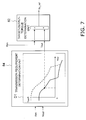
FIG. 7 is a control block diagram illustrating processing executed by the control unit. -
FIG. 8 is a control block diagram illustrating processing executed by the control unit. -
FIG. 9 is a control block diagram illustrating processing executed by the control unit. -
FIG. 10 is a control block diagram illustrating processing executed by the control unit. -
FIG. 11 is a control block diagram illustrating processing executed by the control unit. -
FIG. 12 is a control block diagram illustrating processing executed by the control unit. -
FIG. 13 is a control block diagram illustrating processing executed by the control unit. -
FIG. 14 illustrates changes in a transmission compensation power with respect to the vehicle speed. -
FIG. 15 illustrates a method for distributing output power from an engine. -
FIG. 16 illustrates a method for distributing output power from the engine. -
FIG. 17 is a schematic view illustrating a power transmission device according to a first modified example. -
FIG. 18 is a schematic view illustrating a power transmission device according to a second modified example. -
FIG. 19 is a schematic view illustrating a power transmission device according to a third modified example. - Embodiments of the present invention will be explained in detail with reference to the figures.
FIG. 1 is a side view of awork vehicle 1 according to an embodiment of the present invention. As illustrated inFIG. 1 , thework vehicle 1 is equipped with avehicle body frame 2, a work implement 3, travelingwheels 4 and 5, and anoperating cabin 6. Thework vehicle 1 is a wheel loader and travels due to the travelingwheels 4 and 5 being rotated and driven. Thework vehicle 1 is able to carry out work such as excavation by using the work implement 3. - The work implement 3 and the traveling
wheels 4 are attached to thevehicle body frame 2. The work implement 3 is driven by hydraulic fluid from a belowmentioned work implement pump 23 (seeFIG. 2 ). The work implement 3 has aboom 11 and abucket 12. Theboom 11 is mounted on thevehicle body frame 2. The work implement 3 includes alift cylinder 13 and abucket cylinder 14. Thelift cylinder 13 and thebucket cylinder 14 are hydraulic cylinders. One end of thelift cylinder 13 is attached to thevehicle body frame 2. The other end of thelift cylinder 13 is attached to theboom 11. Theboom 11 swings up and down due to the extension and contraction of thelift cylinder 13 with hydraulic fluid from the work implementpump 23. Thebucket 12 is attached to the tip of theboom 11. One end of thebucket cylinder 14 is attached to thevehicle body frame 2. The other end of thebucket cylinder 14 is attached to thebucket 12 via abell crank 15. Thebucket 12 swings up and down due to the extension and contraction of thebucket cylinder 14 with hydraulic fluid from the work implementpump 23. - The operating
cabin 6 and the traveling wheels 5 are attached to thevehicle body frame 2. The operatingcabin 6 is mounted on thevehicle body frame 2. A seat for the operator and a belowmentioned operating device are disposed in the operatingcabin 6. Thevehicle body frame 2 has afront frame 16 and arear frame 17. Thefront frame 16 and therear frame 17 are attached to each other in a manner that allows swinging in the left-right direction. - The
work vehicle 1 has asteering cylinder 18. Thesteering cylinder 18 is attached to thefront frame 16 and therear frame 17. Thesteering cylinder 18 is a hydraulic cylinder. Thework vehicle 1 is able to change the advancing direction to the right and left with the extension and contraction of thesteering cylinder 18 due to hydraulic fluid from abelowmentioned steering pump 30. -
FIG. 2 is a schematic view of a configuration of thework vehicle 1. As illustrated inFIG. 2 , thework vehicle 1 is equipped with anengine 21, aPTO 22, apower transmission device 24, a travellingapparatus 25, an operatingdevice 26, and acontrol unit 27. - The
engine 21 is, for example, a diesel engine. The output of theengine 21 is controlled by adjusting the amount of fuel injected into the cylinders of theengine 21. The adjustment of the amount of fuel is conducted by thecontrol unit 27 controlling afuel injection device 28 attached to theengine 21. Thework vehicle 1 is equipped with an engine rotationspeed detecting unit 31. The engine rotationspeed detecting unit 31 detects the engine rotation speed and transmits a detection signal indicating the engine rotation speed to thecontrol unit 27. - The
work vehicle 1 has the work implementpump 23, thesteering pump 30, and atransmission pump 29. The work implementpump 23, thesteering pump 30, and thetransmission pump 29 are hydraulic pumps. The PTO 22 (power take-off) transmits a portion of the driving power from theengine 21 to thehydraulic pumps PTO 22 distributes the driving power from thepower transmission device 24 and theengine 21 to thehydraulic pumps - The work implement
pump 23 is driven by driving power from theengine 21. Hydraulic fluid discharged from the work implementpump 23 is supplied to thelift cylinder 13 and thebucket cylinder 14 through a work implementcontrol valve 41. The work implementcontrol valve 41 changes the flow rate of the hydraulic fluid supplied to thelift cylinder 13 and to thebucket cylinder 14 in response to an operation of a belowmentioned work implement operatingmember 52a. Thework vehicle 1 is equipped with a work implement pump pressure detecting unit 32. The work implement pump pressure detecting unit 32 detects a discharge pressure (referred to below as "work implement pump pressure") of hydraulic fluid from the work implementpump 23 and transmits a detection signal indicating the work implement pump pressure to thecontrol unit 27. - The work implement
pump 23 is a variable displacement hydraulic pump. The discharge capacity of the work implementpump 23 is changed by changing the tilt angle of a skew plate or an inclined shaft of the work implementpump 23. The discharge capacity signifies the amount of hydraulic fluid discharged for each single rotation of the work implementpump 23. A firstcapacity control device 42 is connected to the work implementpump 23. The firstcapacity control device 42 is controlled by thecontrol unit 27 and changes the tilt angle of the work implementpump 23. As a result, the discharge capacity of the work implementpump 23 is controlled by thecontrol unit 27. Thework vehicle 1 is equipped with a first tiltangle detecting part 33. The first tiltangle detecting part 33 detects the tilt angle of the work implementpump 23 and transmits a detection signal indicating the tilt angle to thecontrol unit 27. - The
steering pump 30 is driven by driving power from theengine 21. The hydraulic fluid discharged from thesteering pump 30 is supplied to theabovementioned steering cylinder 18 through asteering control valve 43. Thework vehicle 1 is equipped with a steering pumppressure detecting unit 35. The steering pumppressure detecting unit 35 detects the discharge pressure (referred to below as "steering pump pressure") of hydraulic fluid from thesteering pump 30 and transmits a detection signal indicating the steering pump pressure to thecontrol unit 27. - The
steering pump 30 is a variable displacement hydraulic pump. The discharge capacity of thesteering pump 30 is changed by changing the tilt angle of a skew plate or an inclined shaft of thesteering pump 30. A second capacity control device 44 is connected to thesteering pump 30. The second capacity control device 44 is controlled by thecontrol unit 27 and changes the tilt angle of thesteering pump 30. As a result, the discharge capacity of thesteering pump 30 is controlled by thecontrol unit 27. Thework vehicle 1 is equipped with a second tiltangle detecting part 34. The second tiltangle detecting part 34 detects the tilt angle of thesteering pump 30 and transmits a detection signal indicating the tilt angle to thecontrol unit 27. - The
transmission pump 29 is driven by driving power from theengine 21. Thetransmission pump 29 is a fixed displacement hydraulic pump. Hydraulic fluid discharged from thetransmission pump 29 is supplied to clutches CF, CR, CL, and CH of thepower transmission device 24 via belowmentioned clutch control valves VF, VR, VL, and VH. Thework vehicle 1 is equipped with a transmission pumppressure detecting unit 36. The transmission pumppressure detecting unit 36 detects the discharge pressure (referred to below as "transmission pump pressure") of the hydraulic fluid from thetransmission pump 29 and transmits a detection signal indicating the transmission pump pressure to thecontrol unit 27. - The
PTO 22 transmits a portion of the driving power from theengine 21 to thepower transmission device 24. Thepower transmission device 24 transmits the driving power from theengine 21 to the travellingapparatus 25. Thepower transmission device 24 changes the speed and outputs the driving power from theengine 21. An explanation of the configuration of thepower transmission device 24 is provided in detail below. - The travelling
apparatus 25 has anaxle 45 and the travelingwheels 4 and 5. Theaxle 45 transmits driving power from thepower transmission device 24 to the travelingwheels 4 and 5. As a result, the travelingwheels 4 and 5 rotate. Thework vehicle 1 is equipped with a vehiclespeed detecting unit 37. The vehiclespeed detecting unit 37 detects the rotation speed (referred to below as "output rotation speed") of anoutput shaft 63 of thepower transmission device 24. The output rotation speed corresponds to the vehicle speed and consequently the vehiclespeed detecting unit 37 detects the vehicle speed by detecting the output rotation speed. The vehiclespeed detecting unit 37 detects the rotating direction of theoutput shaft 63. The rotating direction of theoutput shaft 63 corresponds to the traveling direction of thework vehicle 1 and consequently the vehiclespeed detecting unit 37 detects the traveling direction of thework vehicle 1 by detecting the rotating direction of theoutput shaft 63. The vehiclespeed detecting unit 37 transmits detection signals indicating the output rotation speed and the rotating direction to thecontrol unit 27. - The operating
device 26 is operated by an operator. The operatingdevice 26 has anaccelerator operating device 51, a work implement operatingdevice 52, a shift operating device 53, anFR operating device 54, asteering operating device 57, and abrake operating device 58. - The
accelerator operating device 51 has anaccelerator operating member 51a and an acceleratoroperation detecting unit 51b. Theaccelerator operating member 51a is operated in order to set a target rotation speed of theengine 21. The acceleratoroperation detecting unit 51b detects an operating amount (referred to below as "accelerator operating amount") of theaccelerator operating member 51a. The acceleratoroperation detecting unit 51b transmits a detection signal indicating the accelerator operating amount to thecontrol unit 27. - The work implement operating
device 52 has a work implement operatingmember 52a and a work implementoperation detecting unit 52b. The work implement operatingmember 52a is operated in order to actuate the work implement 3. The work implementoperation detecting unit 52b detects a position of the work implement operatingmember 52a. The work implementoperation detecting unit 52b outputs a detection signal indicating the position of the work implement operatingmember 52a to thecontrol unit 27. The work implementoperation detecting unit 52b detects an operation amount (referred to below as "boom operation amount") of the work implement operatingmember 52a for operating theboom 11 and an operation amount (referred to below as "bucket operation amount") of the work implement operatingmember 52a for operating thebucket 14, by detecting the position of the work implement operatingmember 52a. The work implement operatingmember 52 is configured for example with one lever and the operation of theboom 11 and the operation of thebucket 14 may be assigned to operating directions of the lever. Alternatively, the work implement operatingmember 52 is configured for example with two levers and the operation of theboom 11 and the operation of thebucket 14 may be assigned to each lever. - The shift operating device 53 has a shift operating member 53a and a shift
operation detecting unit 53b. The operator is able to select a speed range of thepower transmission device 24 by operating the shift operating member 53a. The shiftoperation detecting unit 53b detects a position of the shift operating member 53a. The position of the shift operating member 53a corresponds to a plurality of speed ranges such as a first speed and a second speed and the like. The speed ranges (first speed, second speed, and the like) determined by the shift operating member 53a are referred to herein as variable speed levels. The shiftoperation detecting unit 53b outputs a detection signal indicating the position of the shift operating member 53a to thecontrol unit 27. Specifically, the shiftoperation detecting unit 53b detects the variable speed level and outputs a detection signal indicating the variable speed level to thecontrol unit 27. - The
FR operating device 54 has aFR operating member 54a and a FRoperation detecting unit 54b. The operator can switch between forward and reverse travel of thework vehicle 1 by operating theFR operating member 54a. TheFR operating member 54a is selectively switched between a forward travel position (F), a neutral position (N), and a reverse travel position (R). The FRoperation detecting unit 54b detects a position of theFR operating member 54a. The FRoperation detecting unit 54b outputs a detection signal indicating the position of theFR operating member 54a to thecontrol unit 27. - The
steering operating device 57 has asteering operating member 57a and a steeringoperation detecting unit 57b. The operator is able to change the travel direction of thework vehicle 1 to the right or left by operating thesteering operating member 57a. The steeringoperation detecting unit 57b detects a position of thesteering operating member 57a. The steeringoperation detecting unit 57b outputs a detection signal indicating the position of thesteering operating member 57a to thecontrol unit 27. - The
brake operating device 58 has abrake operating member 58a and a brakeoperation detecting unit 58b. The operator actuates a brake device (not illustrated) to generate a braking force on thework vehicle 1 by operating thebrake operating member 58a. The brakeoperation detecting unit 58b detects a position of thebrake operating member 58a. The brakeoperation detecting unit 58b outputs a detection signal indicating the position of thebrake operating member 58a to thecontrol unit 27. - The
control unit 27 has a calculation device such as a CPU and a memory such as a RAM or a ROM, and conducts various types of processing for controlling thework vehicle 1. Thecontrol unit 27 has astorage unit 56. Thestorage unit 56 stores various types of programs and data for controlling thework vehicle 1. - The
control unit 27 transmits a command signal indicating a command throttle value to thefuel injection device 28 so that a target rotation speed of theengine 21 is obtained in accordance with the accelerator operating amount. The control of theengine 21 by thecontrol unit 27 is described in detail below. - The
control unit 27 controls hydraulic pressure supplied to thehydraulic cylinders control valve 41 on the basis of the detection signals from the work implementoperation detecting unit 52b. As a result, thehydraulic cylinders - The
control unit 27 controls the hydraulic pressure supplied to thesteering cylinder 18 by controlling thesteering control valve 43 on the basis of the detection signals from the steeringoperation detecting unit 57b. As a result, thesteering cylinder 18 is extended and contracted and the traveling direction of thewheel loader 1 is changed. - Specifically, the
storage unit 56 stores work implement control valve command value information which defines the relationship between the work implement operation amount and the command current value to the work implementcontrol valve 41. For example, the work implement control valve command value information is a map which defines the relationship between the work implement operation amount and the command current value to the work implementcontrol valve 41. The work implement control valve command value information may be a table or a formula or in another format other than a map. The opening surface area of the work implementcontrol valve 41 is determined in response to the command current value. The work implement control valve command value information defines the command current value so that the opening surface area of the work implementcontrol valve 41 increases in correspondence to an increase in the work implement operation amount. Thecontrol unit 27 refers to the work implement control valve command value information to determine the command current value to the work implementcontrol valve 41 from the work implement operation amount. - The
control unit 27 controls thepower transmission device 24 on the basis of the detection signals from each of the detecting units. The control of thepower transmission device 24 by thecontrol unit 27 is described in detail below. - Next, a detailed explanation of the configuration of the
power transmission device 24 is provided.FIG. 3 is a schematic view of a configuration of thepower transmission device 24. As illustrated inFIG. 3 , thepower transmission device 24 is provided with aninput shaft 61, agear mechanism 62, theoutput shaft 63, a first motor MG1, a second motor MG2, and acapacitor 64. Theinput shaft 61 is connected to theabovementioned PTO 22. The rotation from theengine 21 is inputted to theinput shaft 61 via thePTO 22. Thegear mechanism 62 transmits the rotation of theinput shaft 61 to theoutput shaft 63. Theoutput shaft 63 is connected to the abovementioned travellingapparatus 25, and transmits the rotation from thegear mechanism 62 to the abovementioned travellingapparatus 25. - The
gear mechanism 62 is a mechanism for transmitting driving power from theengine 21. Thegear mechanism 62 is configured so that the rotation speed ratio of theoutput shaft 63 with respect to theinput shaft 61 is changed in response to changes in the rotation speeds of the motors MG1 and MG2. Thegear mechanism 62 has aFR switch mechanism 65 and atransmission mechanism 66. - The
FR switch mechanism 65 has a forward movement clutch CF, a reverse movement clutch CR, and various types of gears (not illustrated). The forward movement clutch CF and the reverse movement clutch CR are hydraulic clutches and hydraulic fluid is supplied from thetransmission pump 29 to the clutches CF and CR. The hydraulic fluid for the forward movement clutch CF is controlled by an F-clutch control valve VF. The hydraulic fluid for the reverse movement clutch CR is controlled by an R-clutch control valve VR. The clutch control valves CF and CR are controlled by command signals from thecontrol unit 27. The direction of the rotation outputted from theFR switch mechanism 65 is switched due to the switching between ON (connection) / OFF (disconnection) of the forward movement clutch CF and ON (connection) / OFF (disconnection) of the reverse movement clutch CR. - The
transmission mechanism 66 has atransmission shaft 67, a firstplanetary gear mechanism 68, a secondplanetary gear mechanism 69, a Hi/Lo switch mechanism 70, and anoutput gear 71. Thetransmission shaft 67 is coupled to theFR switch mechanism 65. The firstplanetary gear mechanism 68 and the secondplanetary gear mechanism 69 are disposed on the same axis as thetransmission shaft 67. - The first
planetary gear mechanism 68 has a first sun gear S1, a plurality of first planet gears P1, a first carrier C1 that supports the plurality of first planet gears P1, and a first ring gear R1. The first sun gear S1 is coupled to thetransmission shaft 67. The plurality of first planet gears P1 mesh with the first sun gear S1 and are supported in a rotatable manner by the first carrier C1. A first carrier gear Gc1 is provided on an outer peripheral part of the first carrier C1. The first ring gear R1 meshes with the plurality of first planet gears P1 and is able to rotate. A first ring outer periphery gear Gr1 is provided on the outer periphery of the first ring gear R1. - The second
planetary gear mechanism 69 has a second sun gear S2, a plurality of second planet gears P2, a second carrier C2 that supports the plurality of second planet gears P2, and a second ring gear R2. The second sun gear S2 is coupled to the first carrier C1. The plurality of second planet gears P2 mesh with the second sun gear S2 and are supported in a rotatable manner by the second carrier C2. The second ring gear R2 meshes with the plurality of second planet gears P2 and is able to rotate. A second ring outer periphery gear Gr2 is provided on the outer periphery of the second ring gear R2. The second ring outer periphery gear Gr2 meshes with theoutput gear 71, and the rotation of the second ring gear R2 is outputted to theoutput shaft 63 via theoutput gear 71. - The Hi/Lo switch mechanism 70 is a mechanism for switching the driving power transmission path of the
power transmission device 24 between a high-speed mode (Hi-mode) in which the vehicle speed is high and a low-speed mode (Lo-mode) in which the vehicle speed is low. The Hi/Lo switch mechanism 70 has an H-clutch CH that is ON during the Hi-mode and an L-clutch CL that is ON during the Lo-mode. The H-clutch CH connects or disconnects the first ring gear R1 and the second carrier C2. The L-clutch CL connects or disconnects the second carrier C2 and afixed end 72 to prohibit or allow the rotation of the second carrier C2. - The clutches CH and CL are hydraulic clutches, and hydraulic fluid from the
transmission pump 29 is supplied to each of the clutches CH and CL. The hydraulic fluid for the H-clutch CH is controlled by an H-clutch control valve VH. The hydraulic fluid for the L-clutch CL is controlled by an L-clutch control valve VL. The clutch control valves VH and VL are controlled by command signals from thecontrol unit 27. - The first motor MG1 and the second motor MG2 function as drive motors that generate driving power using electrical energy. The first motor MG1 and the second motor MG2 also function as generators that use inputted driving power to generate electrical energy. The first motor MG1 functions as a generator when a command signal from the
control unit 27 is applied so that torque acts in the reverse direction of the rotating direction of the first motor MG1. A first motor gear Gm1 is fixed to the output shaft of the first motor MG1 and the first motor gear Gm1 meshes with the first carrier gear Gc1. A first inverter I1 is connected to the first motor MG1 and a command signal for controlling the motor torque of the first motor MG1 is applied to the first inverter I1 from thecontrol unit 27. - The second motor MG2 is configured in the same way as the first motor MG1. A second motor gear Gm2 is fixed to the output shaft of the second motor MG2 and the second motor gear Gm2 meshes with the first ring outer periphery gear Gr1. A second inverter I2 is connected to the second motor MG2 and a command signal for controlling the motor torque of the second motor MG2 is applied to the second inverter I2 from the
control unit 27. - The
capacitor 64, which as an energy reservoir, stores energy generated by the motors MG1 and MG2. That is, thecapacitor 64 stores electrical power generated by the motors MG1 and MG2 when the total electrical power generation amount of the motors MG1 and MG2 is high. Thecapacitor 64 releases electrical power when the total electrical power consumption amount of the motors MG1 and MG2 is high. That is, the motors MG1 and MG2 are driven by electrical power stored in thecapacitor 64. A battery may be used as another electrical power storage means in place of a capacitor. - The
control unit 27 receives detection signals from the various detecting units and applies command signals for indicating the command torques for the motors MG1 and MG2 to the inverters I1 and I2. Thecontrol unit 27 also applies command signals for controlling the clutch hydraulic pressure of the clutches CF, CR, CH, and CL to the clutch control valves VF, VR, VH, and VL. As a result, the transmission gear ratio and the output torque of thepower transmission device 24 are controlled. The following is an explanation of the operations of thepower transmission device 24. - An outline of operations of the
power transmission device 24 when the vehicle speed increases from zero in the forward movement side while the rotation speed of theengine 21 remains fixed, will be explained with reference toFIG. 4. FIG. 4 illustrates the rotation speeds of the motors MG1 and MG2 with respect to the vehicle speed. When the rotation speed of theengine 21 is fixed, the vehicle speed changes in response to the rotation speed ratio of thepower transmission device 24. The rotation speed ratio is the ratio of the rotation speed of theoutput shaft 63 with respect to the rotation speed of theinput shaft 61. Therefore, the variation in the vehicle speed inFIG. 4 matches the variation of the rotation speed ratio of thepower transmission device 24. That is,FIG. 4 illustrates the relationship between the rotation speeds of the motors MG1 and MG2 and the rotation speed ratio of thepower transmission device 24. The solid line inFIG. 4 represents the rotation speed of the first motor MG1, and the dashed line represents the rotation speed of the second motor MG2. - In an A region (Lo-mode) with a vehicle speed from zero to V1, the L-clutch CL is ON (connected) and the H-clutch CH is OFF (disconnected). Because the H-clutch CH is OFF in the A region, the second carrier C2 and the first ring gear R1 are disconnected. Because the L-clutch CL is ON, the second carrier C2 is fixed.
- The driving power from the
engine 21 in the A region is inputted to the first sun gear S1 via thetransmission shaft 67, and the driving power is outputted from the first carrier C1 to the second sun gear S2. Conversely, the driving power inputted to the first sun gear S1 is transmitted from the first planet gears P1 to the first ring gear R1 and outputted through the first ring outer periphery gear Gr1 and the second motor gear Gm2 to the second motor MG2. The second motor MG2 functions mainly as a generator in the A region, and the electrical power generated by the second motor MG2 is supplied to the first motor MG1 or stored in thecapacitor 64 as needed. - The first motor MG1 functions mainly as an electric motor in the A region. The driving power of the first motor MG1 is outputted to the second sun gear S2 along a path from the first motor gear Gm1 to the first carrier gear Gc1 to the first carrier C1. The driving power outputted to the second sun gear S2 as described above is transmitted to the
output shaft 63 along a path from the second planet gears P2 to the second ring gear R2 to the second ring outer periphery gear Gr2 to theoutput gear 71. - In a B region (Hi-mode) in which the vehicle speed exceeds V1, the H-clutch CH is ON (connected) and the L-clutch CL is OFF (disconnected). Because the H-clutch CH is ON in the B region, the second carrier C2 and the first ring gear R1 are connected. Because the L-clutch CL is OFF, the second carrier C2 is released. Therefore, the rotation speeds of the first ring gear R1 and the second carrier C2 match.
- The driving power from the
engine 21 in the B region is inputted to the first sun gear S1 and the driving power is outputted from the first carrier C1 to the second sun gear S2. The driving power inputted to the first sun gear S1 is outputted from the first carrier C1 through the first carrier gear Gc1 and the first motor gear Gm1 to the first motor MG1. The first motor MG1 functions mainly as a generator in the B region, and thus the electrical power generated by the first motor MG1 is supplied to the first motor MG1 or stored in thecapacitor 64 as needed. - The driving power of the second motor MG2 is outputted to the second carrier C2 along a path from the second motor gear Gm2 to the first ring outer periphery gear Gr1 to the first ring gear R1 to the H-clutch CH. The driving power outputted to the second sun gear S2 as described above is outputted through the second planet gears P2 to the second ring gear R2, and the driving power outputted to the second carrier C2 is outputted through the second planet gears P2 to the second ring gear R2. The driving power combined by the second ring gear R2 in this way is transmitted through the second ring outer periphery gear Gr2 and the
output gear 71 to theoutput shaft 63. - While forward travel driving has been discussed above, the operations of reverse travel driving are the same. During braking, the roles of the first motor MG1 and the second motor MG2 as generator and motor are reversed from the above explanation.
- The control of the
power transmission device 24 by thecontrol unit 27 is described in detail below. Thecontrol unit 27 controls the output torque of the power transmission device by controlling the motor torque of the first motor MG1 and the second motor MG2. That is, thecontrol unit 27 controls the tractive force of thework vehicle 1 by controlling the motor torque of the first motor MG1 and the second motor MG2. - A method for determining the command values (referred to below as "command torques") of the motor torques to the first motor MG1 and the second motor MG2 is explained below.
FIGS. 5 to 13 are control block diagrams illustrating processing executed by thecontrol unit 27. As illustrated inFIGS. 5 and6 , thecontrol unit 27 has a target-input-torque determination unit 81, a target-output-torque determination unit 82, and a command-torque determination unit 83. - The target-input-
torque determination unit 81 determines a target input torque Te_ref. The target input torque Te_ref is a target value for the torque inputted to thepower transmission device 24. The target-output-torque determination unit 82 determines a target output torque To-ref. The target output torque To_ref is a target value for the torque outputted from thepower transmission device 24. The command-torque determination unit 83 uses torque-balance information to determine command torques Tm1_ref and Tm2_ref to the motors MG1 and MG2 from the target input torque Te_ref and the target output torque To_ref. The torque-balance information defines a relationship between the target input torque Te_ref and the target output torque To_ref so as to achieve a balance of the torques of thepower transmission device 24. The torque-balance information is stored in thestorage unit 56. - As described above, the transmission paths of the driving power in the
power transmission device 24 are different for the Lo-mode and the Hi-mode. As a result, the command-torque determination unit 83 uses different torque-balance information to determine the command torques Tm1_ref and Tm2_ref for the motors MG1 and MG2 in the Lo-mode and the Hi-mode. Specifically, the command-torque determination unit 83 uses first torque-balance information represented byequation 1 below to determine command torques Tm1_Low and Tm2_Low for the motors MG1 and MG2 in the Lo-mode. In the present embodiment, the first torque-balance information is an equation for balancing the torques of thepower transmission device 24.

- The command-
torque determination unit 83 uses second torque-balance information represented byequation 2 below to determine command torques Tm1_Hi and Tm2_Hi for the motors MG1 and MG2 in the Hi-mode. In the present embodiment, the second torque-balance information is an equation for balancing the torques of thepower transmission device 24.
- The contents of the parameters in each torque-balance information are depicted in Table 1 below.
[Table 1] Te_ref Target input torque To_ref Target output torque r_fr Deceleration ratio for the FR switch mechanism 65 (The FR switch mechanism 65 outputs the engine rotation speed to decelerate to 1/r_fr. When theFR switch mechanism 65 is in the forward travel state, r_fr is a negative value. When theFR switch mechanism 65 is in the reverse travel state, r_fr is a positive value.)Zs1 Number of teeth of the sun gear S1 in the first planetary gear mechanism 68.Zr1 Number of teeth of the ring gear R1 in the first planetary gear mechanism 68.Zp1 Number of teeth in the first carrier gear Gc1 Zp1d Number of teeth of the first motor gear Gm1 Zs2 Number of teeth of the sun gear S2 in the second planetary gea r mechanism 69.Zr2 Number of teeth of the ring gear R2 in the second planetary ge ar mechanism 69.Zp2 Number of teeth of the first ring outer periphery gear Gr1 Zp2d Number of teeth of the second motor gear Gm2 Zo Number of teeth of the second ring outer periphery gear Gr2 Zod Number of teeth of the output gear 71 - Next, a method for determining the target input torque Te_ref and the target output torque To_ref will be explained. While the target input torque Te_ref and the target output torque To_ref can be set optionally, in the present embodiment the target input torque Te_ref and the target output torque To_ref are determined so that predetermined vehicle speed - tractive force characteristics can be achieved in which the tractive force changes continuously in response to the vehicle speed.
-
FIG. 7 illustrates processing for determining the target output torque To_ref. As illustrated inFIG. 7 , thecontrol unit 27 has a transmissiondemand determination unit 84. The transmissiondemand determination unit 84 determines a required tractive force Tout on the basis of an accelerator operating amount Aac and an output rotation speed Nout. The accelerator operating amount Aac is detected by the acceleratoroperation detecting unit 51b. The output rotation speed Nout is detected by the vehiclespeed detecting unit 37. - The transmission
demand determination unit 84 determines the required tractive force Tout from the output rotation speed Nout on the basis of required tractive force characteristics information D1 stored in thestorage unit 56. The target-output-torque determination unit 82 determines the target output torque To_ref on the basis of the required tractive force Tout. Specifically, the target-output-torque determination unit 82 determines the target output torque To_ref by multiplying a transmission output ratio Rtm by the required tractive force Tout. The transmission output ratio Rtm is explained below. - The required tractive force characteristics information D1 is data indicating the required tractive force characteristics for defining the relationship between the output rotation speed Nout and the required tractive force Tout. The required tractive force characteristics correspond to the abovementioned predetermined vehicle speed - tractive force characteristics. That is, the target output torque To_ref is determined so that the tractive force outputted from the
power transmission device 24 obeys the required tractive force characteristics defined by the required tractive force characteristics information D1. - Specifically as illustrated in
FIG. 8 , thestorage unit 56 stores data Lout1 (referred to below as "basic tractive force characteristics Lout1") indicating basic required tractive force characteristics. The basic tractive force characteristics Lout1 are required tractive force characteristics when the accelerator operating amount Aac is at the maximum value, that is, at 100%. The basic tractive force characteristics Lout1 are determined in response to a speed range selected by the shift operating member 53a. The transmissionrequirement determination unit 84 determines current required tractive force characteristics Lout2 by multiplying a tractive force ratio FWR and a vehicle speed ratio VR by the basic tractive force characteristics Lout1. - The
storage unit 56 stores tractive force ratio information D2 and vehicle speed ratio information D3. The tractive force ratio information D2 defines the tractive force ratio FWR with respect to the accelerator operating amount Aac. The vehicle speed ratio information D3 defines the vehicle speed ratio VR with respect to the accelerator operating amount Aac. The transmissionrequirement determination unit 84 determines the tractive force ratio FWR and the vehicle speed ratio VR in response to the accelerator operating amount Aac. The transmissionrequirement determination unit 84 determines the current required tractive force characteristics Lout2 in response to the accelerator operating amount Aac by multiplying the tractive force ratio FWR in the vertical axis direction which indicates the required tractive force and the vehicle speed ratio VR in the horizontal axis direction which indicates the output rotation speed Nout, by the basic tractive force characteristics Lout1. - The tractive force ratio information D2 defines the tractive force ratio FWR that increases in correspondence to an increase in the accelerator operating amount Aac. The vehicle speed ratio information D3 defines the vehicle speed ratio VR which increases in correspondence to an increase in the accelerator operating amount Aac. However, the tractive force ratio FWR is greater than zero when the accelerator operating amount is zero. Similarly, the vehicle speed ratio VR is greater than zero when the accelerator operating amount Aac is zero. As a result, the required tractive force Tout is a value greater than zero even when the
accelerator operating member 51a is not being operated. That is, tractive force is outputted from thepower transmission device 24 even when theaccelerator operating member 51a is not operated. As a result, a behavior similar to creep generated in a torque converter-type transmission is materialized in the EMT-typepower transmission device 24. - The required tractive force characteristics information D1 defines the required tractive force Tout that increases in response to a reduction in the output rotation speed Nout. When the abovementioned shift operating member 53a is operated, the transmission
requirement determination unit 84 changes the required tractive force characteristics in response to the speed range selected by the shift operating member 53a. For example, when a down-shift is conducted using the shift operating member 53a, the required tractive force characteristics information changes from Lout2 to Lout2' as illustrated inFIG. 8 . As a result, the upper limit of the output rotation speed Nout is reduced. That is, the upper limit of the vehicle speed is reduced. - The required tractive force characteristics information D1 defines the required tractive force Tout as a negative value with respect to the output rotation speed Nout that is equal to or greater than a predetermined speed. As a result, the required tractive force Tout is determined to be a negative value when the output rotation speed Nout is larger than the upper limit of the output rotation speed in the selected speed range. A braking force is generated when the required tractive force Tout is a negative value. As a result, a behavior similar to engine brake generated in a torque converter-type transmission is materialized in the EMT-type
power transmission device 24. -
FIG. 9 illustrates processing for determining the target input torque Te_ref. The target-input-torque determination unit 81 determines the target input torque Te_ref on the basis of a transmission required power Htm and an energy management required power Hem. Specifically, the target-input-torque determination unit 81 calculates a transmission required input power Htm_in by adding the energy management required power Hem to a value derived by multiplying the transmission output ratio Rtm by the transmission required power Htm. The transmission required power Htm is a power required by thepower transmission device 24 for realizing the abovementioned required tractive force characteristics, and is calculated by multiplying the current output rotation speed Nout by the abovementioned required tractive force Tout (seeFIG. 8 ). The energy management required power Hem is a power required by thepower transmission device 24 for charging thebelowmentioned capacitor 64. Therefore, the transmission required input power Htm_in is a power required for the output of a desired tractive force from thepower transmission device 24 and for charging thecapacitor 64 with thepower transmission device 24. However, the Hem being a negative value signifies that charging of thecapacitor 64 is required. - The target-input-
torque determination unit 81 then converts the transmission required input power Htm_in to a torque and determines the target input torque Te_ref so as not to exceed a predetermined upper limit target input torque Max_Te. Specifically, the target-input-torque determination unit 81 calculates a transmission required input torque Tin by dividing the transmission required input power Htm_in by the current engine rotation speed Ne. The target-input-torque determination unit 81 then determines the smaller of the transmission required input torque Tin and the upper limit target input torque Max_Te as the target input torque Te_ref. -
FIG. 10 illustrates processing to determine the upper limit target input torque Max_Te. As illustrated inFIG. 10 , the upper limit target input torque Max_Te is defined by an upper limit target input torque line Lmax_Te+Tpto. Specifically the target-input-torque determination unit 81 determines an upper limit target input torque Max_Te+Tpto from the upper limit target input torque line Lmax_Te+Tpto and the current engine rotation speed Ne. - The upper limit target input torque line Lmax_Te+Tpto is stored in the
storage unit 56 and defines the relationship between the upper limit target input torque Max_Te+Tpto and the engine rotation speed Ne. While the upper limit target input torque line Lmax_Te+Tpto can be set optionally, the upper limit target input torque line Lmax_Te+Tpto in the present embodiment is defined so that the upper limit target input torque Max_Te+Tpto becomes smaller than a target output torque Ten of theengine 21 determined from the transmission required input power Htm_in and the current engine rotation speed Ne. - The upper limit target input torque Max_Te+Tpto derived from the upper limit target input torque line Lmax_Te+Tpto defines the upper limit of the target input torque that is a combination of both the transmission required input torque Tin and a work implement load torque Tpto. The work implement load torque Tpto is a torque distributed to the
hydraulic pump 23 through thebelowmentioned PTO 22. Therefore, the target-input-torque determination unit 81 calculates the upper limit target input torque Max_Te as the upper limit of the target input torque Te_ref by subtracting the work implement load torque Tpto from the upper limit target input torque Max_Te+Tpto which is derived from the upper limit target input torque line Lmax_Te+Tpto. - The
storage unit 56 stores an engine torque line Let. The engine torque line Let defines the relationship between the output torque of theengine 21 and the engine rotation speed Ne. The engine torque line Let includes a regulation region La and a full load region Lb. An explanation of the regulation region La is provided below. The full load region Lb depicts the maximum torque that can be outputted by the engine in each of the engine rotation speeds Ne. The intersection Plmax of the upper limit target input torque line Lmax_Te+Tpto and the engine torque line Let (specifically the full load region Lb) is referred to herein as a maximum matching point. The engine rotation speed Ne corresponding to the maximum matching point Plmax is referred to as a first rotation speed Ne_th. - Next, a method for determining the energy management required power Hem will be explained. As illustrated in
FIG. 9 , thecontrol unit 27 has an energy managementrequirement determination unit 85. The energy managementrequirement determination unit 85 determines the energy management required power Hem on the basis of a remaining amount of electrical power in thecapacitor 64. - Specifically, the
storage unit 56 stores target capacitor capacity information D4. The target capacitor capacity information D4 defines the relationship between the output rotation speed Nout and a target capacitor capacity Cp_target. Specifically, the energy managementrequirement determination unit 85 defines the target capacitor capacity Cp_target which grows smaller as the output rotation speed Nout increases. The energy managementrequirement determination unit 85 refers to the target capacitor capacity information D4 to determine the target capacitor capacity Cp_target from the output rotation speed Nout. The energy managementrequirement determination unit 85 determines a current capacitor capacity Cp_current from a voltage Vca of thecapacitor 64. The energy managementrequirement determination unit 85 then determines the energy management required power Hem using the following equation 3.
- P_gain is a predetermined coefficient. The energy management
requirement determination unit 85 increases the energy management required power Hem as the current capacitor capacity Cp_current becomes smaller. The energy managementrequirement determination unit 85 increases the energy management required power Hem as the target capacitor capacity Cp_target becomes larger. - The control of the
engine 21 by thecontrol unit 27 is described in detail below. As described above, thecontrol unit 27 controls the engine by transmitting command signals to thefuel injection device 28. A method for determining the command throttle values for thefuel injection device 28 will be explained below. - A command throttle value Th_cm is determined on the basis of an engine required power Hdm required by the engine 21 (see
FIG. 12 ). As described above, a portion of the driving power from theengine 21 is distributed to thepower transmission device 24 and the work implementpump 23 and the like. As a result, thecontrol unit 27 determines the engine required power Hdm on the basis of a work implement required power Hpto, which is the power distributed to the work implementpump 23, added to the abovementioned transmission required power Htm and the energy management required power Hem. - As illustrated in
FIG. 11 , thecontrol unit 27 has a work implementrequirement determination unit 86. The work implementrequirement determination unit 86 determines the work implement required power Hpto on the basis of a work implement pump pressure Pwp and an operation amount Awo (referred to below as "work implement operation amount Awo") of the work implement operatingmember 52a. In the present embodiment, the work implement required power Hpto is a power distributed to the work implementpump 23. - Specifically, the work implement
requirement determination unit 86 determines a required flow rate Qdm of the work implementpump 23 from the work implement operating amount Awo on the basis of required flow rate information D5. The required flow rate information D5 is stored in thestorage unit 56 and defines the relationship between the required flow rate Qdm and the work implement operation amount Awo. The work implementrequirement determination unit 86 determines the work implement required power Hpto from the required flow rate Qdm and the work implement pump pressure Pwp. Specifically, the work implementrequirement determination unit 86 determines the work implement required power Hpto using thefollowing equation 4.
- ηv is a volume efficiency. ηt is a torque efficiency. The volume efficiency ηv and the torque efficiency ηt are fixed values determined in accordance with the characteristics of the work implement
pump 23. The work implement pump pressure Pwp is detected by the work implement pump pressure detecting unit 32. - The work implement
requirement determination unit 86 determines the abovementioned work implement load torque Tpto on the basis of the work implement pump pressure Pwp and a work implement output flow rate Qwo. The work implement pump pressure Pwp may be defined with a maximum pressure such as a relief pressure. Specifically, the work implementrequirement determination unit 86 determines the work implement load torque Tpto using the following equation 5.
- Qwp is the displacement volume of the work implement pump. The work implement pump displacement volume Qwp is calculated from the tilt angle detected by the first tilt
angle detecting part 33. - The work implement
requirement determination unit 86 determines the work implement output flow rate Qwo on the basis of the work implement operation amount Awo. Specifically the work implementrequirement determination unit 86 determines the work implement output flow rate Qwo by multiplying the required flow rate Qdm by a work implement output ratio Rpto. The work implement output ratio Rpto is described below. Thecontrol unit 27 controls the discharge capacity of the work implementpump 23 in response to the work implement output flow rate Qwo determined as described above. - Furthermore, the work implement
requirement determination unit 86 determines a work implement required engine rotation speed Nedm on the basis of the required flow rate Qdm and the discharge capacity of the work implementpump 23. Specifically, the work implementrequirement determination unit 86 determines the work implement required engine rotation speed Nedm on the basis of the required flow rate Qdm, the maximum discharge capacity Qmax of the work implement pump, and the volume efficiency ηv using thefollowing equation 6.
- As illustrated in
FIG. 12 , thecontrol unit 27 has an enginerequirement determination unit 87. The enginerequirement determination unit 87 determines the engine required power Hdm on the basis of the work implement required power Hpto, the transmission required power Htm, and the energy management required power Hem. The enginerequirement determination unit 87 determines the engine required power Hdm by adding together the work implement required power Hpto, the transmission required power Htm, and the energy management required power Hem. - As illustrated in
FIG. 13 , thecontrol unit 27 has a requiredthrottle determination unit 89. The requiredthrottle determination unit 89 determines the command throttle value Th_cm from the engine required power Hdm, the accelerator operating amount Aac, and the work implement required engine rotation speed Nedm. - Specifically, the
storage unit 56 stores an engine torque line Let and a matching line Lma. The engine torque line Let defines the relationship between the output torque of theengine 21 and the engine rotation speed Ne. The engine torque line Let includes the regulation region La and the full load region Lb. The regulation region La changes in response to the command throttle value Th_cm (see La' inFIG. 13 ). The full load region Lb includes a rated point Pr and a maximum torque point Pm located on the low engine rotation speed side from the rated point Pr. - The matching line Lma is information for determining a first required throttle value Th_tm1 from the engine required power Hdm. While the matching line Lma can be set optionally, the matching line Lma in the present embodiment is set so as to pass through a position closer to the maximum torque point Pm than the rated point Pr in the full load region Lb of the engine torque line Let.
- The required
throttle determination unit 89 determines the first required throttle value Th_tm1 so that the engine torque line Let and the matching line Lma match at a matching point Pma1 where the output torque of theengine 21 becomes the torque corresponding to the engine required power Hdm. That is, the intersection of the matching line Lma and an equivalent power line Lhdm corresponding to the engine required power Hdm is set as a first matching point Pma1, and the requiredthrottle determination unit 89 determines the first required throttle value Th_tm1 so that the regulation region (see La') of the engine torque line Let passes through the first matching point Pma1. - The required
throttle determination unit 89 determines the lowest of the first required throttle value Th_tm1 and a second required throttle value Th_tm2 corresponding to the accelerator operating amount Aac, as a third command throttle value Th_tm3. When the work implement operation amount Awo exceeds a predetermined threshold that represents the maximum capacity of the discharge capacity of the work implementpump 23, the requiredthrottle determination unit 89 determines a fourth required throttle value Th_tm4 on the basis of the work implement required engine rotation speed Nedm in order to increase the speed of the work implement. Specifically, the requiredthrottle determination unit 89 determines the fourth required throttle value Th_tm4 so that the regulation region (see La") of the engine torque line Let passes through a point Pma2 in which the engine rotation speed on the engine required power Hdm becomes the work implement required engine rotation speed Nedm. The requiredthrottle determination unit 89 determines the largest of the third command throttle value Th_tm3 and the fourth required throttle value Th_tm4 as the command throttle value Th_cm. If the work implement operation amount Awo does not exceed the predetermined threshold, the requiredthrottle determination unit 89 determines the third command throttle value Th_tm3 as the command throttle value Th_cm. - A method for determining the abovementioned transmission output ratio Rtm and the work implement output ratio Rpto will be explained next. As illustrated in
FIG. 12 , thecontrol unit 27 has a distributionratio determination unit 88. The distributionratio determination unit 88 determines the transmission output ratio Rtm and the work implement output ratio Rpto on the basis of the work implement required power Hpto, the transmission required power Htm, the energy management required power Hem, a PTO fixed power Hfix, and a load upper limit power Hmax of theengine 21. The following is an explanation of the load upper limit power Hmax of theengine 21. The PTO fixed power Hfix is a power for driving a hydraulic pump for auxiliary equipment and includes, for example, power distributed to the steering pump 40 and/or thetransmission pump 29. Alternatively, when thework vehicle 1 is provided with a cooling fan for cooling theengine 21, a fan motor for driving the cooling fan, and a fan pump for driving the fan motor, the hydraulic pump for auxiliary equipment may include the fan pump. In this case, the PTO fixed power Hfix may include the power for driving the fan pump. Moreover, the PTO fixed power Hfix may include power for lubrication. The PTO fixed power Hfix is determined on the basis of the engine rotation speed and the operation amount of thesteering operating member 57a and the like. - The output power from the
engine 21 is distributed to the hydraulic pumps such as the work implementpump 23 and to thepower transmission device 24 by thePTO 22. The output power for thepower transmission device 24 is distributed between the power for the tractive force of thepower transmission device 24 and the power for the charging to thecapacitor 64. However, when the sum of the work implement required power Hpto, the transmission required power Htm, and the energy management required power Hem is greater than the output power from theengine 21, the output power from theengine 21 cannot be distributed according to each of the requirement values. As a result, the sum of the requirement values is limited so as not to exceed the output power from theengine 21 by multiplying the work implement required power Hpto and the transmission required power Htm by the respective output ratios Rpto and Rtm. - Specifically, when the sum of the work implement required power Hpto, the transmission required power Htm, the energy management required power Hem, and the PTO fixed power Hfix is equal to or less than the load upper limit power Hmax, the transmission output ratio Rtm and the work implement output ratio Rpto are each set to "1." That is, the output power from the
engine 21 is distributed according to each of the requirement values of the work implement required power Hpto, the transmission required power Htm, and the energy management required power Hem. When the sum of the work implement required power Hpto, the transmission required power Htm, the energy management required power Hem, and the PTO fixed power Hfix is greater than the load upper limit power Hmax, at least one of the transmission output ratio Rtm and the work implement output ratio Rpto is set to a value less than "1." - The load upper limit power Hmax of the
engine 21 is determined on the basis of the current engine rotation speed Ne when the engine rotation speed Ne is less than the first rotation speed Ne_th. Specifically, the load upper limit power Hmax is determined from the abovementioned upper limit target input torque Max_Te+Tpto and the current engine rotation speed Ne as illustrated inFIG. 10 . That is, the load upper limit power Hmax is calculated on the basis of the torque value of the upper limit target input torque Max_Te+Tpto at the current engine rotation speed Ne. When the engine rotation speed Ne is set as the work implement required engine rotation speed Nedm due to the abovementioned engine rotation control (seeFIG. 13 ), the engine rotation speed Ne exceeds the first rotation speed Ne_th. In this case, a load upper limit power Hplmax at the maximum matching point Plmax is considered as the load upper limit power Hmax of theengine 21. As illustrated inFIG. 10 , while the engine rotation speed Ne is in a range exceeding the first rotation speed Ne_th, the torque in the full load region Lb multiplied by the engine rotation speed Ne exceeds the load upper limit power Hplmax at the maximum matching point Plmax. Therefore, engine stall will not occur even if the load upper limit power Hplmax at the maximum matching point Plmax is considered as the load upper limit power Hmax. - Next, the distribution
ratio determination unit 88 determines a preferential distribution power Hprior according toequation 7.
- The distribution
ratio determination unit 88 then determines a distributable power Hdiv that the calculated preferential distribution power Hprior subtracted from the load upper limit power Hmax leaves. The distributable power is represented as in equation 8.
- Here, Max (A, B) represents the larger of A and B.
- Next, a transmission compensation power Htc is calculated. The transmission compensation power Htc simulates the absorption power of a torque converter. The absorption torque of the torque converter is proportional to a primary torque coefficient determined from a ratio between the input rotation speed and the output rotation speed of the torque converter and to the square of the input rotation speed of the torque converter. Therefore, when there is no driving of the work implement and the work vehicle is traveling at a fixed vehicle speed, the absorption power of the torque converter increases in correspondence to an increase in the engine rotation speed. In other words, the absorption power decreases and the power allocated to the work implement increases in correspondence to an increase in the vehicle speed even at the same engine rotation speed. Therefore, if it is assumed that a load on the work implement increases while the vehicle is traveling at a fixed vehicle speed, the engine rotation speed gradually falls and the absorption power decreases. The transmission compensation power Htc is simulated as in
FIG. 14 in consideration of the above property of the torque converter.FIG. 14 illustrates changes in a transmission compensation power with respect to the vehicle speed. - The vehicle speed Vveh in
FIG. 14 is calculated from the output rotation speed Nout. When the absolute value of the vehicle speed Vveh is in the range from zero up to an including a first speed Vth1, the transmission compensation power Htc is a first power Htc_max. When the absolute value of the vehicle speed Vveh is equal to or greater than a second speed Vth2, the transmission compensation power Htc is a second power Htc_min. The first power Htc_max and the second power Htc_min are fixed values and previously stored in thestorage unit 56. The second power Htc_min is smaller than the first power Htc_max. The first speed Vth1 and the second speed Vth2 are set in response to a variable speed level detected by the shiftoperation detecting unit 53b. The first speed Vth1 and the second speed Vth2 are described in detail below. - When the absolute value of the vehicle speed Vveh is in the range from the first speed Vth1 up to the second speed Vth2, the transmission compensation power Htc is represented by the following equation 9.
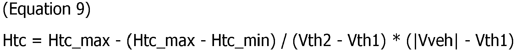
- That is, when the absolute value of the vehicle speed Vveh is in the range from the first speed Vth1 up to the second speed Vth2, the transmission compensation power Htc becomes increasingly smaller than the first power Htc_max as the absolute value of the vehicle speed Vveh increases.
- A method for setting the first speed Vth1 and the second speed Vth2 will be explained next. The first speed Vth1 and the second speed Vth2 are respective products of predetermined initial values Vth1_org and Vth2_org (where Vth2_org > Vth1_org) multiplied by a coefficient Km (m is a natural number, and m = 1 at the first speed, m = 2 at the second speed, and so on) corresponding to the variable speed level. Specifically, the first speed Vth1 and the second speed Vth2 are represented by the following equation 10.

- Here, the coefficient Km increases in correspondence to an increase in the level number m of the variable speed level. Specifically, the coefficient K2 at the second speed is greater than the coefficient K1 at the first speed. The coefficient K3 at the third speed is greater than the coefficient K2 at the second speed. The coefficient K4 at the fourth speed is greater than the coefficient K3 at the third speed.
- Next, the distribution
ratio determination unit 88 carries out the following processing when the load upper limit power Hmax of theengine 21 is the load upper limit power Hplmax at the maximum matching point Plmax, that is, when the engine rotation speed Ne is equal to or greater than the first rotation speed Ne_th and the sum of the work implement required power Hpto and the transmission required power Htm is greater than the distributable power Hdiv. - The distribution
ratio determination unit 88 first calculates a transmission preferential distribution power Htpa in accordance with the followingequation 11.
- Here, Min (A, B, C) represents the smallest value among A, B, and C. When Min (A, B) is indicated in the following explanation, Min (A, B) represents the smallest value among A and B.
- The transmission preferential distribution power Htpa is allocated to the
power transmission device 24. That is, the distributionratio determination unit 88 allocates the smaller of the transmission compensation power Htc and the transmission required power Htm to thepower transmission device 24. - Next, the distribution
ratio determination unit 88 calculates a work implement allocation power Hla in accordance with the followingequation 12.
- The distribution
ratio determination unit 88 then calculates a transmission addition distribution power Htaa in accordance with the followingequation 13.
- The distribution
ratio determination unit 88 finally calculates a transmission allocation power Hta in accordance with the followingequation 14.
- As described above, the distribution
ratio determination unit 88 distributes, to the work implementpump 23 and thepower transmission device 24, the power Hdiv - Min (Htc, Htm) which is the power resulting from excluding the smaller of the transmission compensation power Htc and the transmission required power Htm from the distributable power Hdiv. Consequently, the distributionratio determination unit 88 determines the work implement allocation power Hla allocated to the work implementpump 23 and the transmission allocation power Hta allocated to thepower transmission device 24. The distributionratio determination unit 88 also determines the work implement allocation power Hla before determining the transmission allocation power Hta. Therefore, the distributionratio determination unit 88 preferentially allocates the power Hdiv - Min (Htc, Htm) remaining from the distributable power to the work implementpump 23 before thepower transmission device 24 so that the work implement required power Hpto can be preferentially secured. - Finally, the distribution
ratio determination unit 88 determines the transmission output ratio Rtm and the work implement output ratio Rpto according to the followingequation 15.
- Next, the operations of the distribution
ratio determination unit 88 will be explained on the basis of a specific example. For example as illustrated inFIG. 15 , when the sum of the preferential distribution power Hprior, the work implement required power Hpto, and the transmission required power Htm (Hprior + Hpto + Htm) is greater than the load upper limit power Hmax but the sum of the preferential distribution power Hprior, the work implement required power Hpto, and the transmission compensation power Htc (however, the transmission compensation power Htc is smaller than the transmission required power Htm) is less than the load upper limit power Hmax, the transmission required power Htm is corrected to Htm' which is less than Htm so that the above sums are no greater than the load upper limit power Hmax. The ratio of the transmission required power Htm' (the driving power actually supplied from theengine 21 to the power transmission device 24) after correction with respect to the transmission required power Htm before correction is determined as the transmission output ratio Rtm. In this case, the work implement output ratio Rpto is set to "1." - Next, the distribution
ratio determination unit 88 carries out the following processing when the load upper limit power Hmax of theengine 21 is less than the load upper limit power Hplmax at the maximum matching point Plmax, that is, when the engine rotation speed Ne is less than the first rotation speed Ne_th and the sum of the work implement required power Hpto and the transmission required power Htm is greater than the distributable power Hdiv. - Similarly, the distribution
ratio determination unit 88 determines the distributable power Hdiv and the transmission compensation power Htc on the basis of equations 8 to 10. Next, the distributionratio determination unit 88 assumes that the load upper limit power Hmax of theengine 21 is the load upper limit power Hplmax at the maximum matching point Plmax and calculates a temporary work implement allocation power Hla_tmp and a temporary transmission allocation power Hta_tmp in accordance with theequations 11 to 15. - The distribution
ratio determination unit 88 then calculates a second transmission preferential distribution power Htpa2 in accordance with the followingequation 16.
- Here, Hcrp represents a creep power. The creep power Hcrp is a power required by the
power transmission device 24 for enabling the work vehicle to perform creeping. Specifically, the creep power Hcrp is the minimum power required for thework vehicle 1 to travel. - The second transmission preferential distribution power Htpa2 is allocated to the
power transmission device 24. That is, the distributionratio determination unit 88 allocates the smaller of the creep power Hcrp and the transmission required power Htm to thepower transmission device 24. - Next, the distribution
ratio determination unit 88 calculates a work implement proportional allocation power Hla_prop in accordance with the followingequation 17.
- The distribution
ratio determination unit 88 then determines the work implement proportional allocation power Hla_prop so that the ratio of the temporary transmission allocation power Hta_tmp with respect to the temporary work implement allocation power Hla_tmp and the ratio of a transmission proportional allocation power Hta_prop with respect to the work implement proportional allocation power Hla_prop are equal and so that the sum of the work implement proportional allocation power Hla_prop and the transmission proportional allocation power Hta_prop becomes the distributable power Hdiv. - Next, a second work implement allocation power Hla2 is calculated according to the following
equation 18.
- The distribution
ratio determination unit 88 then calculates a second transmission addition distribution power Htaa2 in accordance with the following equation 19.
- The distribution
ratio determination unit 88 finally calculates a second transmission allocation power Hta2 in accordance with the following equation 20.
- As described above, the distribution
ratio determination unit 88 distributes, to the work implementpump 23 and thepower transmission device 24, the power Hdiv - Min (Hcrp, Htm) which is the power resulting from excluding the smaller of the creep power Hcrp and the transmission required power Htm from the distributable power Hdiv. Consequently, the distributionratio determination unit 88 determines the second work implement allocation power Hla2 allocated to the work implementpump 23 and the second transmission allocation power Hta2 allocated to thepower transmission device 24. The distributionratio determination unit 88 also determines the second work implement allocation power Hla2 before determining the second transmission allocation power Hta2. Therefore, the distributionratio determination unit 88 preferentially allocates the power Hdiv - Min (Hcrp, Htm) remaining from the distributable power to the work implementpump 23 before thepower transmission device 24 so that the smaller of the work implement required power Hpto and the work implement proportional allocation power Hla_prop can be preferentially secured. - Finally, the distribution
ratio determination unit 88 determines the transmission output ratio Rtm and the work implement output ratio Rpto in accordance with the followingequation 21.
- Next, the operations of the distribution
ratio determination unit 88 will be explained on the basis of a specific example. For example as illustrated inFIG. 16 , when the sum of the preferential distribution power Hprior, the work implement required power Hpto, and the transmission required power Htm (Hprior + Hpto + Htm) is greater than the load upper limit power Hmax but the sum of the preferential distribution power Hprior, the work implement proportional allocation power Hla_prop (however, the work implement proportional allocation power Hla_prop is less than the work implement required power Hpto), and the creep power Hcrp (however, the creep power is less than the transmission required power Htm) is less than the load upper limit power Hmax, the transmission required power Htm is corrected to Htm'" which is less than Htm and the work implement required power Hpto is corrected to Hpto" which is less than Hpto so that the above sums are no greater than the load upper limit power Hmax. The ratio of the transmission required power Htm" (the driving power actually supplied from theengine 21 to the power transmission device 24) after correction with respect to the transmission required power Htm before correction is determined as the transmission output ratio Rtm. Moreover, the ratio of the work implement required power Hpto" (the driving power actually supplied from theengine 21 to the work implement pump 23) after correction with respect to the work implement required power Hpto before correction is determined as the work implement output ratio Rpto. - The
work vehicle 1 according to the present embodiment has the following features. (1) When the driving power of theengine 21 is less than the entire required power of thework vehicle 1 and the transmission required power Htm is greater than the transmission compensation power Htc, the control unit 27 (distribution ratio determination unit 88) preferentially allocates the transmission compensation power Htc to thepower transmission device 24. The transmission compensation power Htc simulates the power absorbed by a torque converter. Therefore, thecontrol unit 27 is able to distribute the driving power from theengine 21 to the driving power for traveling the vehicle and the driving power for the work implement with a method that is similar to a work vehicle equipped with a torque converter-type transmission. - (2) The control unit 27 (distribution ratio determination unit 88) preferentially allocates the transmission compensation power Htc to the
power transmission device 24 and preferentially allocates the power Hdiv - Min (Htc, Htm) remaining from the distributable power to the work implementpump 23 before thepower transmission device 24 so that the work implement required power Hpto can be preferentially secured. A work vehicle having a torque converter-type transmission requires time for accelerating after stopping the operation of the work implement. This is because the engine rotation speed drops due to the driving power of the engine being split with the work implement when the work implement is being operated, and then time is required thereafter for the engine rotation speed to rise in order to generate tractive force during acceleration. However, thework vehicle 1 enables the quick allocation of the driving power corresponding to the work implement required power Hpto to thepower transmission device 24 even if the work implement required power Hpto falls quickly. Therefore, the actuation of the travellingapparatus 25 can be realized in a way that allows the operating intention of the operator to be reflected as quickly as possible. - (3) When the rotation speed Ne of the
engine 21 is less than the first rotation speed Ne_th, the load upper limit power Hmax of theengine 21 becomes smaller than the power Hplmax at the maximum matching point Plmax. In this way, even if the load upper limit power Hmax is small, the control unit 27 (distribution ratio determination unit 88) preferentially allocates the creep power Hcrp to thepower transmission device 24. The creep power Hcrp is the minimum power required for thework vehicle 1 to travel. Therefore, when the load upper limit power Hmax is small, thecontrol unit 27 secures the supply of the minimum power required for thework vehicle 1 to travel to thepower transmission device 24 while being able to distribute the driving power from theengine 21 to the driving power for the vehicle to travel and to the driving power for the work implement. Even in this case, thework vehicle 1 enables the quick allocation of the driving power corresponding to the work implement required power Hpto" after correction to thepower transmission device 24 even if the work implement required power Hpto falls quickly. Therefore, the actuation of the travellingapparatus 25 can be realized in a way that allows the operating intention of the operator on the work implement 3 to be reflected as quickly as possible. - (4) The control unit 27 (distribution ratio determination unit 88) preferentially allocates the creep power Hcrp to the
power transmission device 24 and preferentially allocates the power Hdiv - Min (Hcrp, Htm) remaining from the distributable power to the work implementpump 23 before thepower transmission device 24 so that the smaller of the work implement required power Hpto and the work implement proportional allocation power Hla_prop can be preferentially secured. As a result, even if the load upper limit power Hmax of theengine 21 is small in thework vehicle 1, the load upper limit power Hmax can be distributed with as good a balance as possible to thepower transmission device 24 and the work implementpump 23. Therefore, the actuation of the work implement 3 can be realized in a way that allows the operating intention of the operator on the work implement 3 to be reflected as quickly as possible. - (5) The preferential distribution power Hprior includes the energy management required power Hem. Therefore, charging of the
capacitor 64 is performed preferentially. Therefore, energy management is carried out in a stable manner in thework vehicle 1 equipped with the EMT transmission. - (6) The transmission compensation power Htc is the first power Htc_max when the absolute value of the vehicle speed Vveh is in the range from zero up to the first speed Vth1, and falls further below the first power Htc_max as the absolute value of the vehicle speed Vveh increases when the absolute value of the vehicle speed Vveh is in the range from the first speed Vth1 up to the second speed Vth2, and the transmission compensation power Htc is the second power Htc_min when the absolute value of the vehicle speed Vveh is equal to or greater than the second speed Vth2. Therefore, when the engine rotation speed is the same, the transmission compensation power Htc is simulated in accordance with the properties of the absorption power of a torque converter so that the absorption power decreases and the power allocated to the work implement increases as the vehicle speed increases.
- (7) The first speed Vth1 and the second speed Vth2 are set to larger values as the variable speed level detected by the shift
operation detecting unit 53b increases. When the variable speed level is large, the speed ratio is set so that the ratio of the output rotation speed Nout with respect to the engine rotation speed Ne increases in thepower transmission device 24. The changes in the first speed Vth1 and the second speed Vth2 with respect to the variable speed level as described above corresponds to changes in the speed ratio thereof. - (8) The
control unit 27 is able to obtain the desired input torque for thepower transmission device 24 and the desired output torque from thepower transmission device 24 by determining the command torques Tm1_ref and Tm2_ref to the motors MG1 and MG2 from the balance of the torques of thepower transmission device 24. As a result, predetermined tractive force characteristics in particular can be obtained accurately in thework vehicle 1 equipped with an EMT or HMT transmission. Generally, a work vehicle is required to conduct work while the tractive force and the loads on the work implement fluctuate greatly. Therefore, the ability to adjust the input torque and the output torque to the power transmission device to desired values is desirable in order to obtain a balance between the driving power and the operation of the work implement. By adjusting the target input torque Te_ref and the target output torque To_ref in thework vehicle 1 according to the present embodiment, the desired input torque to thepower transmission device 24 and the desired output torque from thepower transmission device 24 can be obtained. As a result, a work vehicle combining both operability and drivability can be realized. - The present invention is not limited to the above embodiments and various changes and modifications may be made without departing from the spirit of the invention.
- The present invention is not limited to the abovementioned wheel loader and may be applied to another type of work vehicle such as a bulldozer, a tractor, a forklift, or a motor grader.
- The present invention may be applicable to another type of transmission such as a HMT without being limited to the EMT. In this case, the first motor MG1 functions as a hydraulic motor and a hydraulic pump. The second motor MG2 functions as a hydraulic motor and a hydraulic pump. The first motor MG1 and the second motor MG2 are variable capacitor pump/motors, and the capacities are controlled by the
control unit 27 controlling the tilt angle of the skew plate or the inclined shaft. The capacities of the first motor MG1 and the second motor MG2 are controlled so that the command torques Tm1_ref and Tm2_ref calculated in the same way as in the above embodiments are outputted. - The configuration of the
power transmission device 24 is not limited to the configuration of the above embodiments. For example, the coupling and disposition of the elements of the twoplanetary gear mechanisms power transmission device 24 is not limited to two. Thepower transmission device 24 may only have one planetary gear mechanism. Alternatively, thepower transmission device 24 may have three or more planetary gear mechanisms. - The torque-balance information is not limited to the equations for balancing the torque as in the above embodiment. For example, the torque-balance information may be in the format of a table or a map. The torque-balance information is not limited to the abovementioned two types of torque-balance information including the first torque-balance information and the second torque-balance information. Three or more types of torque-balance information may be used in combination with a selectable number of modes in the
power transmission device 24 when the driving power drivetrain of thepower transmission device 24 has three or more modes. Alternatively, only one torque-balance information may be used when there is only one driving power drivetrain for thepower transmission device 24. - The shift operating member 53a may have a kick-down switch. A kick-down switch is an operating member for lowering the speed range of the
power transmission device 24 by one stage or a plurality of stages from the current speed range. The operator is able to lower the speed range of thepower transmission device 24 from the current speed range to a low-speed speed range by operating the kick-down switch. - The model of the transmission compensation power Htc is not limited to the model depicted in
FIG. 14 . Another model of the transmission compensation power Htc may be used so long as the model is based on the properties of a torque converter in which the absorption torque of a torque converter is determined from a ratio of the input rotation speed and the output rotation speed of the torque converter. - The power transmission device is not limited to a so-called split system device using the planetary gear mechanism as described above, and may use a device of another system. For example,
FIG. 17 is a schematic view illustrating apower transmission device 124 according to a modified example. Thepower transmission device 124 illustrated inFIG. 17 is a so-called series system power transmission device. Theengine 21 in thepower transmission device 124 only uses the first motor MG1 to generate electricity. The second motor MG2 uses the electrical power generated in the first motor MG1 to drive the travelling apparatus. The second motor MG2 also generates electricity by recovering energy during deceleration. - Alternatively, a parallel system
power transmission device 224 as illustrated inFIG. 18 may be used.FIG. 18 is a schematic view illustrating apower transmission device 224 according to a second modified example. The driving power of theengine 21 in thepower transmission device 224 is transmitted via thegear mechanism 62 to theoutput shaft 62. Theoutput shaft 62 is driven by driving power from the motor MG1. The motor MG1 generates electricity by regenerating energy during deceleration. - Alternatively, the power transmission device is not limited to a so-called hybrid power transmission device that uses the motors as described above. For example,
FIG. 19 is a schematic view illustrating apower transmission device 324 according to a third modified example. Thepower transmission device 324 is a so-called hydro-static transmission (HST) device. Thepower transmission device 324 has atravel pump 301 and atravel motor 302. Thetravel pump 301 is driven by theengine 21. Thetravel pump 301 is a variable capacity hydraulic pump and the capacity of thetravel pump 301 is controlled by a pumpcapacity control device 303. Thetravel motor 302 drives the travelling apparatus by being driven by hydraulic fluid discharged from thetravel pump 301. Thetravel motor 302 is a variable capacity hydraulic motor and the capacity of thetravel motor 302 is controlled by a motorcapacity control device 304. The vehicle speed and the tractive force are controlled by controlling the engine rotation speed, the capacity of thetravel pump 301, and the capacity of thetravel motor 302 and the like. - Configurations that are the same in the above embodiment are provided with the same reference numerals in
FIG. 17, 18 and19 and explanations thereof are omitted. - When the transmission of the
work vehicle 1 is an HST or an HMT, thework vehicle 1 may not have the inverters I1 or I2, thecapacitor 64, or the energy managementrequirement determination unit 85. Therefore, the preferential distribution power Hprior may not include the energy management required power Hem. - The present invention is able to demonstrate the effect of being able to distribute the driving power from the engine to driving power for traveling the vehicle and to driving power for the work implement with a method that is similar to that of a work vehicle equipped with a torque converter-type transmission. Therefore the present invention is useful as a work vehicle equipped with a transmission such as a HMT, an EMT, or a HST and as a work vehicle control method.
-
- 21:
- Engine
- 23:
- Work implement pump
- 3:
- Work implement
- 25:
- Travelling apparatus
- 24, 124:
- Power transmission device
- 27:
- Control unit
- 37:
- Vehicle speed detecting unit
- 51a:
- Accelerator operating member
- 51b:
- Accelerator operation detecting unit
- 52a:
- Work implement operating member
- 53a:
- Shift operating member
- 53b:
- Shift operation detecting member
- 56:
- Storage device
- 61:
- Input shaft
- 63:
- Output shaft
- 64:
- Capacitor (energy reservoir)
- MG1:
- First motor
- MG2:
- Second motor
- 81:
- Target-input-torque determination unit
- 82:
- Target-output-torque determination unit
- 83:
- Command-torque determination unit
- 84:
- Transmission requirement determination unit
- 85:
- Energy management requirement determination unit
- 86:
- Work implement requirement determination unit
- 87:
- Engine requirement determination unit
- 88:
- Distribution ratio determination unit
Claims (9)
- A work vehicle comprising:an engine;a work implement pump driven by the engine;a work implement driven by hydraulic fluid discharged from the work implement pump;a travelling apparatus driven by the engine;a power transmission device including at least an input shaft for inputting driving power from the engine, an output shaft for outputting driving power transmitted to the travelling apparatus, and a motor;a vehicle speed detecting unit configured to detect a vehicle speed;a work implement pump pressure detecting unit configured to detect a work implement pump pressure of the work implement pump;a work implement operating member for operating the work implement;a work implement operation detecting unit configured to detect an operation amount of the work implement operating member;an accelerator operating member;an accelerator operation detecting unit configured to detect an operation amount of the accelerator operating member;a control unit configured to control the power transmission device;the power transmission device being configured so that a rotation speed ratio of the output shaft with respect to the input shaft is changed by changing the rotation speed of the motor;the control unit including:a work implement requirement determination unit configured to determine a work implement required power on the basis of an operation amount of the work implement operating member and the work implement pump pressure;a transmission requirement determination unit configured to determine a transmission required power on the basis of the vehicle speed and the operation amount of the accelerator operating member; anda distribution ratio determination unit configured to determine a transmission output ratio that is a value derived by dividing the driving power actually supplied from the engine to the power transmission device by the transmission required power, and a work implement output ratio that is a value derived by dividing the driving power actually supplied from the engine to the work implement pump by the work implement required power, wherein,in a first casein which the engine rotates at a rotation speed equal to or greater than a first rotation speed that is the rotation speed of the engine at a maximum matching point where an upper limit target input torque line and an engine torque line intersect andin which the sum of the work implement required power and the transmission required power is greater than a first distributable power that a predetermined preferential distribution power subtracted from a load upper limit power of the engine at the first rotation speed leaves,the distribution ratio determination unit is configured to allocate the smaller of a transmission compensation power and the transmission required power to the power transmission device and distribute the remainder of the first distributable power to the work implement pump and to the power transmission device, thereby determining a first work implement allocation power allocated to the work implement pump and a first transmission allocation power allocated to the power transmission device.
- The work vehicle according to claim 1, wherein
the distribution ratio determination unit is configured to preferentially allocate the remainder of the first distributable power to the work implement pump over the power transmission device so as to be able to preferentially secure the work implement required power in the first case. - The work vehicle according to claim 1 or 2, wherein:when the engine rotates at a second rotation speed lower than the first rotation speed, the load upper limit power of the engine at the second rotation speed is calculated on the basis of a torque value of the upper limit target input torque line at the second rotation speed; andin a second casein which the engine rotates at the second rotation speed andin which the sum of the work implement required power and the transmission required power is greater than a second distributable power that the preferential distribution power subtracted from the load upper limit power of the engine at the second rotation speed leaves,the distribution ratio determination unit is configured to allocate the smaller of a creep power and the transmission required power to the power transmission device, the creep power being required by the power transmission device so that the work vehicle travels at the minimum speed, and to distribute the remainder of the second distributable power to the work implement pump and to the power transmission device, thereby determining a second work implement allocation power allocated to the work implement pump and a second transmission allocation power allocated to the power transmission device.
- The work according to claim 3, wherein:in the second case, the distribution ratio determination unit is configured to:determine the first work implement allocation power and the first transmission allocation power, assuming a case in which the engine rotates at the first rotation speed;determine a work implement proportional allocation power so that the ratio of the first transmission allocation power with respect to the first work implement allocation power and the ratio of a transmission proportional allocation power with respect to a work implement proportional allocation power are equal and so that a sum of the work implement proportional allocation power and the transmission proportional allocation power is equal to the second distributable power; andpreferentially allocates the remainder of the second distributable power to the work implement pump over the power transmission device so as to be able to preferentially secure the smaller of the work implement required power and the work implement proportional allocation power.
- The work vehicle according to any one of claims 1 to 4, further comprising:an energy reservoir for storing energy generated in the motor; wherein,the control unit further includes an energy management requirement determination unit for determining an energy management required power on the basis of a remaining amount of energy in the energy reservoir, andthe preferential distribution power includes the energy management required power.
- The work vehicle according to any one of claims 1 to 5, wherein:the transmission compensation power is a predetermined first power while an absolute value of the vehicle speed is in a range from zero up to a first speed;the transmission compensation power becomes correspondingly smaller than the first power as the absolute value of the vehicle speed increases while an absolute value of the vehicle speed is in a range from the first speed up to a second speed greater than the first speed; andthe transmission compensation power is a predetermined second power smaller than the first power when the absolute value of the vehicle speed is equal to or greater than the second speed.
- The work vehicle according to claim 6, further comprising:a shift operating member anda shift operation detecting unit configured to detect a position of the shift operating member; wherein,the first speed and the second speed are set in response to a variable speed level detected by the shift operation detecting unit.
- The work vehicle according to any one of claims 1 to 7, wherein
the control unit further includes:a target-input-torque determination unit configured to determine a target input torque that is a torque target value inputted to the power transmission device;a target-output-torque determination unit configured to determine a target output torque which is a torque target value outputted from the power transmission device;a storage unit configured to store torque-balance information defining a relationship between the target input torque and the target output torque so as to achieve a balance of the torques in the power transmission device; anda command-torque determination unit configured to use the torque-balance information to determine a command torque for the motor from the target input torque and the target output torque. - A control method for a work vehicle,
the work vehicle equipped with: an engine; a work implement pump driven by the engine; a work implement driven by hydraulic fluid discharged from the work implement pump; a travelling apparatus driven by the engine; a power transmission device including at least an input shaft for inputting driving power from the engine, an output shaft for outputting driving power transmitted to the travelling apparatus, and a motor; a vehicle speed detecting unit configured to detect a vehicle speed; a work implement pump pressure detecting unit configured to detect a work implement pump pressure of the work implement pump; a work implement operating member for operating the work implement; a work implement operation detecting unit configured to detect an operation amount of the work implement operating member; an accelerator operating member; and an accelerator operation detecting unit configured to detect an operation amount of the accelerator operating member; the power transmission device being configured so that a rotation speed ratio of the output shaft with respect to the input shaft is changed by changing the rotation speed of the motor, the method including:a step of determining a work implement required power on the basis of an operation amount of the work implement operating member and the work implement pump pressure;a step of determining a transmission required power on the basis of the vehicle speed and the operation amount of the accelerator operating member; anda step of determining a transmission output ratio that is a value derived by dividing the driving power actually supplied from the engine to the power transmission device by the transmission required power, and a work implement output ratio that is a value derived by dividing the driving power actually supplied from the engine to the work implement pump by the work implement required power, whereinin a first casein which the engine rotates at a rotation speed equal to or greater than a first rotation speed that is the rotation speed of the engine at a maximum matching point where an upper limit target input torque line and an engine torque line intersect andin which the sum of the work implement required power and the transmission required power is greater than a first distributable power that a predetermined preferential distribution power subtracted from a load upper limit power of the engine at the first rotation speed leaves,the step for determining the transmission output ratio and the work implement output ratio includes allocating the smaller of a transmission compensation power and the transmission required power to the power transmission device and distributing the remainder of the first distributable power to the work implement pump and to the power transmission device, thereby determining a first work implement allocation power allocated to the work implement pump and a first transmission allocation power allocated to the power transmission device.
Applications Claiming Priority (2)
| Application Number | Priority Date | Filing Date | Title |
|---|---|---|---|
| JP2014005028A JP6403386B2 (en) | 2014-01-15 | 2014-01-15 | Work vehicle and control method of work vehicle |
| PCT/JP2014/083411 WO2015107829A1 (en) | 2014-01-15 | 2014-12-17 | Work vehicle, and work vehicle control method |
Publications (3)
| Publication Number | Publication Date |
|---|---|
| EP2993098A1 true EP2993098A1 (en) | 2016-03-09 |
| EP2993098A4 EP2993098A4 (en) | 2017-04-12 |
| EP2993098B1 EP2993098B1 (en) | 2020-10-07 |
Family
ID=53542731
Family Applications (1)
| Application Number | Title | Priority Date | Filing Date |
|---|---|---|---|
| EP14878674.2A Active EP2993098B1 (en) | 2014-01-15 | 2014-12-17 | Work vehicle, and work vehicle control method |
Country Status (5)
| Country | Link |
|---|---|
| US (1) | US9593468B2 (en) |
| EP (1) | EP2993098B1 (en) |
| JP (1) | JP6403386B2 (en) |
| CN (1) | CN105307888B (en) |
| WO (1) | WO2015107829A1 (en) |
Cited By (2)
| Publication number | Priority date | Publication date | Assignee | Title |
|---|---|---|---|---|
| EP3795755A4 (en) * | 2019-03-13 | 2022-02-16 | Hitachi Construction Machinery Co., Ltd. | Cargo handling work vehicle |
| EP3892505A4 (en) * | 2019-03-28 | 2022-10-19 | Komatsu Ltd. | Work machine and method for controlling work machine |
Families Citing this family (10)
| Publication number | Priority date | Publication date | Assignee | Title |
|---|---|---|---|---|
| JP6364194B2 (en) * | 2014-01-29 | 2018-07-25 | 株式会社小松製作所 | Work vehicle and control method thereof |
| CN107306500B (en) * | 2016-02-29 | 2020-07-10 | 株式会社小松制作所 | Control device for work machine, and control method for work machine |
| CN106284179B (en) * | 2016-08-31 | 2019-09-20 | 天嘉智能装备制造江苏股份有限公司 | Round brush revolving speed following control system based on snow sweeper operating rate |
| US10619330B2 (en) * | 2016-11-08 | 2020-04-14 | Guangxi Liugong Machinery Co., Ltd. | Multiple level work hydraulics anti-stall |
| CN106740855B (en) * | 2016-12-28 | 2019-03-29 | 潍柴动力股份有限公司 | A kind of power distribution control method and device of mobile operation vehicle |
| JP6603716B2 (en) * | 2017-04-06 | 2019-11-06 | 株式会社小松製作所 | Work vehicle and control method of work vehicle |
| US10920399B2 (en) * | 2017-06-27 | 2021-02-16 | Komatsu Ltd. | Work vehicle and control method for work vehicle |
| CN108666498A (en) * | 2018-08-11 | 2018-10-16 | 深圳市道通科技股份有限公司 | A kind of Auto analyzer and its battery warehouse component |
| WO2020192905A1 (en) * | 2019-03-27 | 2020-10-01 | Volvo Truck Corporation | A method for controlling a vehicle |
| CN115289212A (en) * | 2022-08-31 | 2022-11-04 | 潍柴动力股份有限公司 | Determination method and determination device for input torque of gearbox, processor and vehicle |
Family Cites Families (14)
| Publication number | Priority date | Publication date | Assignee | Title |
|---|---|---|---|---|
| US5980410A (en) * | 1998-09-28 | 1999-11-09 | Caterpillar Inc. | Electro-mechanical transmission |
| US6319170B1 (en) * | 2000-05-19 | 2001-11-20 | General Motors Corporation | Model-based engine torque control for power-on downshifting in an automatic transmission |
| JP4368117B2 (en) * | 2003-02-12 | 2009-11-18 | 株式会社小松製作所 | Gearbox for work vehicle |
| JP4764018B2 (en) * | 2005-01-25 | 2011-08-31 | 株式会社小松製作所 | Traveling work machine |
| JP4789507B2 (en) * | 2005-05-24 | 2011-10-12 | 株式会社小松製作所 | Transmission |
| JP4725406B2 (en) * | 2006-04-26 | 2011-07-13 | コベルコ建機株式会社 | Power source device for hybrid work machines |
| WO2009037877A1 (en) * | 2007-09-20 | 2009-03-26 | Kubota Corporation | Shifting transmission |
| DE102007062888A1 (en) * | 2007-12-28 | 2009-07-02 | Robert Bosch Gmbh | Method for controlling a hydrostatic drive |
| US8744695B2 (en) * | 2009-03-27 | 2014-06-03 | Komatsu Ltd. | Fuel consumption saving control device for work vehicle and fuel consumption saving method for work vehicle |
| JP5249857B2 (en) * | 2009-05-29 | 2013-07-31 | 株式会社神戸製鋼所 | Control device and work machine equipped with the same |
| CN103189576B (en) * | 2010-10-15 | 2016-10-12 | 日立建机株式会社 | Engineering machinery |
| JP5351918B2 (en) * | 2011-03-15 | 2013-11-27 | 日立建機株式会社 | Construction machinery |
| US8858395B2 (en) * | 2012-04-30 | 2014-10-14 | Caterpillar Inc. | Torque control system |
| JP5873458B2 (en) * | 2013-04-15 | 2016-03-01 | 住友建機株式会社 | Excavator and excavator turning control method |
-
2014
- 2014-01-15 JP JP2014005028A patent/JP6403386B2/en active Active
- 2014-12-17 WO PCT/JP2014/083411 patent/WO2015107829A1/en active Application Filing
- 2014-12-17 CN CN201480031605.5A patent/CN105307888B/en active Active
- 2014-12-17 EP EP14878674.2A patent/EP2993098B1/en active Active
- 2014-12-17 US US14/892,703 patent/US9593468B2/en active Active
Cited By (2)
| Publication number | Priority date | Publication date | Assignee | Title |
|---|---|---|---|---|
| EP3795755A4 (en) * | 2019-03-13 | 2022-02-16 | Hitachi Construction Machinery Co., Ltd. | Cargo handling work vehicle |
| EP3892505A4 (en) * | 2019-03-28 | 2022-10-19 | Komatsu Ltd. | Work machine and method for controlling work machine |
Also Published As
| Publication number | Publication date |
|---|---|
| EP2993098A4 (en) | 2017-04-12 |
| JP6403386B2 (en) | 2018-10-10 |
| US9593468B2 (en) | 2017-03-14 |
| WO2015107829A1 (en) | 2015-07-23 |
| CN105307888B (en) | 2017-11-28 |
| EP2993098B1 (en) | 2020-10-07 |
| US20160097186A1 (en) | 2016-04-07 |
| CN105307888A (en) | 2016-02-03 |
| JP2015131606A (en) | 2015-07-23 |
Similar Documents
| Publication | Publication Date | Title |
|---|---|---|
| EP2918465B1 (en) | Work vehicle and method for controlling work vehicle | |
| EP2993098B1 (en) | Work vehicle, and work vehicle control method | |
| US9790663B2 (en) | Work vehicle having a work implement | |
| EP2942439B1 (en) | Work vehicle and control method for same | |
| EP2927071B1 (en) | Work vehicle with control unit for power transmission device and method of operating the control unit of the work vehicle | |
| EP2949530A1 (en) | Work vehicle, and method of controlling same | |
| EP2990287A1 (en) | Work vehicle, and method of controlling same | |
| EP3040584A1 (en) | Work vehicle, and work vehicle control method | |
| EP3053797B1 (en) | Work vehicle, and work vehicle control method | |
| US10174483B2 (en) | Work vehicle and method for controlling work vehicle |
Legal Events
| Date | Code | Title | Description |
|---|---|---|---|
| PUAI | Public reference made under article 153(3) epc to a published international application that has entered the european phase |
Free format text: ORIGINAL CODE: 0009012 |
|
| 17P | Request for examination filed |
Effective date: 20151203 |
|
| AK | Designated contracting states |
Kind code of ref document: A1 Designated state(s): AL AT BE BG CH CY CZ DE DK EE ES FI FR GB GR HR HU IE IS IT LI LT LU LV MC MK MT NL NO PL PT RO RS SE SI SK SM TR |
|
| AX | Request for extension of the european patent |
Extension state: BA ME |
|
| A4 | Supplementary search report drawn up and despatched |
Effective date: 20170313 |
|
| RIC1 | Information provided on ipc code assigned before grant |
Ipc: B60K 6/50 20071001ALI20170307BHEP Ipc: B60K 25/02 20060101ALI20170307BHEP Ipc: F02D 29/00 20060101ALI20170307BHEP Ipc: E02F 9/20 20060101ALI20170307BHEP Ipc: B60W 10/06 20060101ALI20170307BHEP Ipc: B60W 20/00 20160101AFI20170307BHEP Ipc: B60K 6/547 20071001ALI20170307BHEP Ipc: B60K 6/28 20071001ALI20170307BHEP Ipc: B60W 10/30 20060101ALI20170307BHEP Ipc: F02D 29/04 20060101ALI20170307BHEP Ipc: F16H 3/72 20060101ALI20170307BHEP Ipc: B60K 6/445 20071001ALI20170307BHEP Ipc: F16H 3/66 20060101ALI20170307BHEP |
|
| DAX | Request for extension of the european patent (deleted) | ||
| GRAP | Despatch of communication of intention to grant a patent |
Free format text: ORIGINAL CODE: EPIDOSNIGR1 |
|
| STAA | Information on the status of an ep patent application or granted ep patent |
Free format text: STATUS: GRANT OF PATENT IS INTENDED |
|
| INTG | Intention to grant announced |
Effective date: 20200515 |
|
| GRAS | Grant fee paid |
Free format text: ORIGINAL CODE: EPIDOSNIGR3 |
|
| GRAA | (expected) grant |
Free format text: ORIGINAL CODE: 0009210 |
|
| STAA | Information on the status of an ep patent application or granted ep patent |
Free format text: STATUS: THE PATENT HAS BEEN GRANTED |
|
| AK | Designated contracting states |
Kind code of ref document: B1 Designated state(s): AL AT BE BG CH CY CZ DE DK EE ES FI FR GB GR HR HU IE IS IT LI LT LU LV MC MK MT NL NO PL PT RO RS SE SI SK SM TR |
|
| REG | Reference to a national code |
Ref country code: GB Ref legal event code: FG4D |
|
| REG | Reference to a national code |
Ref country code: AT Ref legal event code: REF Ref document number: 1320887 Country of ref document: AT Kind code of ref document: T Effective date: 20201015 Ref country code: CH Ref legal event code: EP |
|
| REG | Reference to a national code |
Ref country code: DE Ref legal event code: R096 Ref document number: 602014071113 Country of ref document: DE |
|
| REG | Reference to a national code |
Ref country code: IE Ref legal event code: FG4D |
|
| REG | Reference to a national code |
Ref country code: SE Ref legal event code: TRGR |
|
| REG | Reference to a national code |
Ref country code: NL Ref legal event code: MP Effective date: 20201007 |
|
| REG | Reference to a national code |
Ref country code: AT Ref legal event code: MK05 Ref document number: 1320887 Country of ref document: AT Kind code of ref document: T Effective date: 20201007 |
|
| PG25 | Lapsed in a contracting state [announced via postgrant information from national office to epo] |
Ref country code: GR Free format text: LAPSE BECAUSE OF FAILURE TO SUBMIT A TRANSLATION OF THE DESCRIPTION OR TO PAY THE FEE WITHIN THE PRESCRIBED TIME-LIMIT Effective date: 20210108 Ref country code: RS Free format text: LAPSE BECAUSE OF FAILURE TO SUBMIT A TRANSLATION OF THE DESCRIPTION OR TO PAY THE FEE WITHIN THE PRESCRIBED TIME-LIMIT Effective date: 20201007 Ref country code: FI Free format text: LAPSE BECAUSE OF FAILURE TO SUBMIT A TRANSLATION OF THE DESCRIPTION OR TO PAY THE FEE WITHIN THE PRESCRIBED TIME-LIMIT Effective date: 20201007 Ref country code: PT Free format text: LAPSE BECAUSE OF FAILURE TO SUBMIT A TRANSLATION OF THE DESCRIPTION OR TO PAY THE FEE WITHIN THE PRESCRIBED TIME-LIMIT Effective date: 20210208 Ref country code: NL Free format text: LAPSE BECAUSE OF FAILURE TO SUBMIT A TRANSLATION OF THE DESCRIPTION OR TO PAY THE FEE WITHIN THE PRESCRIBED TIME-LIMIT Effective date: 20201007 Ref country code: NO Free format text: LAPSE BECAUSE OF FAILURE TO SUBMIT A TRANSLATION OF THE DESCRIPTION OR TO PAY THE FEE WITHIN THE PRESCRIBED TIME-LIMIT Effective date: 20210107 |
|
| REG | Reference to a national code |
Ref country code: LT Ref legal event code: MG4D |
|
| PG25 | Lapsed in a contracting state [announced via postgrant information from national office to epo] |
Ref country code: IS Free format text: LAPSE BECAUSE OF FAILURE TO SUBMIT A TRANSLATION OF THE DESCRIPTION OR TO PAY THE FEE WITHIN THE PRESCRIBED TIME-LIMIT Effective date: 20210207 Ref country code: PL Free format text: LAPSE BECAUSE OF FAILURE TO SUBMIT A TRANSLATION OF THE DESCRIPTION OR TO PAY THE FEE WITHIN THE PRESCRIBED TIME-LIMIT Effective date: 20201007 Ref country code: LV Free format text: LAPSE BECAUSE OF FAILURE TO SUBMIT A TRANSLATION OF THE DESCRIPTION OR TO PAY THE FEE WITHIN THE PRESCRIBED TIME-LIMIT Effective date: 20201007 Ref country code: AT Free format text: LAPSE BECAUSE OF FAILURE TO SUBMIT A TRANSLATION OF THE DESCRIPTION OR TO PAY THE FEE WITHIN THE PRESCRIBED TIME-LIMIT Effective date: 20201007 Ref country code: ES Free format text: LAPSE BECAUSE OF FAILURE TO SUBMIT A TRANSLATION OF THE DESCRIPTION OR TO PAY THE FEE WITHIN THE PRESCRIBED TIME-LIMIT Effective date: 20201007 Ref country code: BG Free format text: LAPSE BECAUSE OF FAILURE TO SUBMIT A TRANSLATION OF THE DESCRIPTION OR TO PAY THE FEE WITHIN THE PRESCRIBED TIME-LIMIT Effective date: 20210107 |
|
| PG25 | Lapsed in a contracting state [announced via postgrant information from national office to epo] |
Ref country code: HR Free format text: LAPSE BECAUSE OF FAILURE TO SUBMIT A TRANSLATION OF THE DESCRIPTION OR TO PAY THE FEE WITHIN THE PRESCRIBED TIME-LIMIT Effective date: 20201007 |
|
| REG | Reference to a national code |
Ref country code: DE Ref legal event code: R097 Ref document number: 602014071113 Country of ref document: DE |
|
| PG25 | Lapsed in a contracting state [announced via postgrant information from national office to epo] |
Ref country code: CZ Free format text: LAPSE BECAUSE OF FAILURE TO SUBMIT A TRANSLATION OF THE DESCRIPTION OR TO PAY THE FEE WITHIN THE PRESCRIBED TIME-LIMIT Effective date: 20201007 Ref country code: EE Free format text: LAPSE BECAUSE OF FAILURE TO SUBMIT A TRANSLATION OF THE DESCRIPTION OR TO PAY THE FEE WITHIN THE PRESCRIBED TIME-LIMIT Effective date: 20201007 Ref country code: SM Free format text: LAPSE BECAUSE OF FAILURE TO SUBMIT A TRANSLATION OF THE DESCRIPTION OR TO PAY THE FEE WITHIN THE PRESCRIBED TIME-LIMIT Effective date: 20201007 Ref country code: LT Free format text: LAPSE BECAUSE OF FAILURE TO SUBMIT A TRANSLATION OF THE DESCRIPTION OR TO PAY THE FEE WITHIN THE PRESCRIBED TIME-LIMIT Effective date: 20201007 Ref country code: RO Free format text: LAPSE BECAUSE OF FAILURE TO SUBMIT A TRANSLATION OF THE DESCRIPTION OR TO PAY THE FEE WITHIN THE PRESCRIBED TIME-LIMIT Effective date: 20201007 Ref country code: SK Free format text: LAPSE BECAUSE OF FAILURE TO SUBMIT A TRANSLATION OF THE DESCRIPTION OR TO PAY THE FEE WITHIN THE PRESCRIBED TIME-LIMIT Effective date: 20201007 |
|
| REG | Reference to a national code |
Ref country code: CH Ref legal event code: PL |
|
| PLBE | No opposition filed within time limit |
Free format text: ORIGINAL CODE: 0009261 |
|
| STAA | Information on the status of an ep patent application or granted ep patent |
Free format text: STATUS: NO OPPOSITION FILED WITHIN TIME LIMIT |
|
| PG25 | Lapsed in a contracting state [announced via postgrant information from national office to epo] |
Ref country code: MC Free format text: LAPSE BECAUSE OF FAILURE TO SUBMIT A TRANSLATION OF THE DESCRIPTION OR TO PAY THE FEE WITHIN THE PRESCRIBED TIME-LIMIT Effective date: 20201007 Ref country code: DK Free format text: LAPSE BECAUSE OF FAILURE TO SUBMIT A TRANSLATION OF THE DESCRIPTION OR TO PAY THE FEE WITHIN THE PRESCRIBED TIME-LIMIT Effective date: 20201007 |
|
| REG | Reference to a national code |
Ref country code: BE Ref legal event code: MM Effective date: 20201231 |
|
| 26N | No opposition filed |
Effective date: 20210708 |
|
| GBPC | Gb: european patent ceased through non-payment of renewal fee |
Effective date: 20210107 |
|
| PG25 | Lapsed in a contracting state [announced via postgrant information from national office to epo] |
Ref country code: IE Free format text: LAPSE BECAUSE OF NON-PAYMENT OF DUE FEES Effective date: 20201217 Ref country code: IT Free format text: LAPSE BECAUSE OF FAILURE TO SUBMIT A TRANSLATION OF THE DESCRIPTION OR TO PAY THE FEE WITHIN THE PRESCRIBED TIME-LIMIT Effective date: 20201007 Ref country code: LU Free format text: LAPSE BECAUSE OF NON-PAYMENT OF DUE FEES Effective date: 20201217 Ref country code: FR Free format text: LAPSE BECAUSE OF NON-PAYMENT OF DUE FEES Effective date: 20201231 Ref country code: AL Free format text: LAPSE BECAUSE OF FAILURE TO SUBMIT A TRANSLATION OF THE DESCRIPTION OR TO PAY THE FEE WITHIN THE PRESCRIBED TIME-LIMIT Effective date: 20201007 |
|
| PG25 | Lapsed in a contracting state [announced via postgrant information from national office to epo] |
Ref country code: CH Free format text: LAPSE BECAUSE OF NON-PAYMENT OF DUE FEES Effective date: 20201231 Ref country code: GB Free format text: LAPSE BECAUSE OF NON-PAYMENT OF DUE FEES Effective date: 20210107 Ref country code: SI Free format text: LAPSE BECAUSE OF FAILURE TO SUBMIT A TRANSLATION OF THE DESCRIPTION OR TO PAY THE FEE WITHIN THE PRESCRIBED TIME-LIMIT Effective date: 20201007 Ref country code: LI Free format text: LAPSE BECAUSE OF NON-PAYMENT OF DUE FEES Effective date: 20201231 |
|
| PG25 | Lapsed in a contracting state [announced via postgrant information from national office to epo] |
Ref country code: IS Free format text: LAPSE BECAUSE OF FAILURE TO SUBMIT A TRANSLATION OF THE DESCRIPTION OR TO PAY THE FEE WITHIN THE PRESCRIBED TIME-LIMIT Effective date: 20210207 Ref country code: TR Free format text: LAPSE BECAUSE OF FAILURE TO SUBMIT A TRANSLATION OF THE DESCRIPTION OR TO PAY THE FEE WITHIN THE PRESCRIBED TIME-LIMIT Effective date: 20201007 Ref country code: MT Free format text: LAPSE BECAUSE OF FAILURE TO SUBMIT A TRANSLATION OF THE DESCRIPTION OR TO PAY THE FEE WITHIN THE PRESCRIBED TIME-LIMIT Effective date: 20201007 Ref country code: CY Free format text: LAPSE BECAUSE OF FAILURE TO SUBMIT A TRANSLATION OF THE DESCRIPTION OR TO PAY THE FEE WITHIN THE PRESCRIBED TIME-LIMIT Effective date: 20201007 |
|
| PG25 | Lapsed in a contracting state [announced via postgrant information from national office to epo] |
Ref country code: MK Free format text: LAPSE BECAUSE OF FAILURE TO SUBMIT A TRANSLATION OF THE DESCRIPTION OR TO PAY THE FEE WITHIN THE PRESCRIBED TIME-LIMIT Effective date: 20201007 |
|
| PG25 | Lapsed in a contracting state [announced via postgrant information from national office to epo] |
Ref country code: BE Free format text: LAPSE BECAUSE OF NON-PAYMENT OF DUE FEES Effective date: 20201231 |
|
| PGFP | Annual fee paid to national office [announced via postgrant information from national office to epo] |
Ref country code: SE Payment date: 20231110 Year of fee payment: 10 Ref country code: DE Payment date: 20231031 Year of fee payment: 10 |