EP2992668B1 - Annulation d'écho à canaux multiples et suppression du bruit - Google Patents
Annulation d'écho à canaux multiples et suppression du bruit Download PDFInfo
- Publication number
- EP2992668B1 EP2992668B1 EP14726292.7A EP14726292A EP2992668B1 EP 2992668 B1 EP2992668 B1 EP 2992668B1 EP 14726292 A EP14726292 A EP 14726292A EP 2992668 B1 EP2992668 B1 EP 2992668B1
- Authority
- EP
- European Patent Office
- Prior art keywords
- echo
- estimate
- noise
- linear
- masking
- Prior art date
- Legal status (The legal status is an assumption and is not a legal conclusion. Google has not performed a legal analysis and makes no representation as to the accuracy of the status listed.)
- Not-in-force
Links
Images


Classifications
-
- H—ELECTRICITY
- H04—ELECTRIC COMMUNICATION TECHNIQUE
- H04R—LOUDSPEAKERS, MICROPHONES, GRAMOPHONE PICK-UPS OR LIKE ACOUSTIC ELECTROMECHANICAL TRANSDUCERS; DEAF-AID SETS; PUBLIC ADDRESS SYSTEMS
- H04R3/00—Circuits for transducers, loudspeakers or microphones
- H04R3/002—Damping circuit arrangements for transducers, e.g. motional feedback circuits
-
- H—ELECTRICITY
- H04—ELECTRIC COMMUNICATION TECHNIQUE
- H04M—TELEPHONIC COMMUNICATION
- H04M9/00—Arrangements for interconnection not involving centralised switching
- H04M9/08—Two-way loud-speaking telephone systems with means for conditioning the signal, e.g. for suppressing echoes for one or both directions of traffic
- H04M9/082—Two-way loud-speaking telephone systems with means for conditioning the signal, e.g. for suppressing echoes for one or both directions of traffic using echo cancellers
Definitions
- the present disclosure relates generally to electronic devices. More specifically, the present disclosure relates to multi-channel echo cancellation and noise suppression.
- Electronic devices have become a part of everyday life. Small computing devices are now placed in everything from automobiles to housing locks. The complexity of electronic devices has increased dramatically in the last few years. For example, many electronic devices have one or more processors that help control the device, as well as a number of digital circuits to support the processor and other parts of the device.
- Wireless communication systems are widely deployed to provide various types of communication content such as voice, video, data and so on. These systems may be multiple-access systems capable of supporting simultaneous communication of multiple communication devices with one or more base stations.
- a communication device may use various signal processing techniques. These techniques may attempt to recreate/preserve a speaker's voice while eliminating unwanted sounds. Therefore, benefits may be realized by systems and methods for multi-channel echo cancellation and noise suppression.
- US 7 359 504 B1 discloses a method and apparatus for reducing echo and noise, in which echo controllers utilize a summing/subtracting device to subtract a generated estimate of an echo signal component from an enhanced voice signal and enhanced noise signal.
- US 2012/249785 discloses a signal processor and signal processing method, in which an echo interval estimator notifies an acoustic characteristic estimator of an echo interval in which it is estimated that an echo occurs.
- US 2007/263850 discloses a two-way voice communication system in which the outputs of a plurality of microphones are provided to acoustic echo cancellation (AEC) blocks, whose outputs are in turn provided to a sound source localization (SSL) process and a residual echo suppression (RES) process.
- a microphone array process combines an SSL estimate output from the SSL process with the outputs of the RES process to produce a processed mono speech signal.
- a method for multi-channel echo cancellation and noise suppression as in claim 1 is described.
- One of multiple echo estimates is selected for non-linear echo cancellation.
- Echo notch masking is performed on a noise-suppressed signal based on an echo direction of arrival (DOA) to produce an echo-suppressed signal.
- Non-linear echo cancellation is performed on the echo-suppressed signal based, at least in part, on the selected echo estimate.
- DOA echo direction of arrival
- the one of multiple echo estimates may be one of a spatial-processed echo estimate, a primary microphone echo estimate and a secondary microphone echo estimate.
- the selecting one of multiple echo estimates may include selecting a maxima of the multiple echo estimates.
- the selecting one of multiple echo estimates may include combining multiple echo estimates to produce the selected echo estimate.
- Echo notch masking may include determining a masking gain based on a speech likelihood and the echo DOA. Echo notch masking may also include applying the masking gain to the noise-suppressed signal to produce the echo-suppressed signal.
- Performing non-linear echo cancellation may include using a non-linear model of echo based on the selected echo estimate and the echo-suppressed signal.
- a computer-program product for multi-channel echo cancellation and noise as in claim 6 is also described.
- the computer-program product includes a non-transitory computer-readable medium having instructions thereon.
- the instructions include code for causing a communication device to select one of multiple echo estimates for non-linear echo cancellation.
- the instructions also include code for causing the communication device to perform echo notch masking on a noise-suppressed signal based on an echo DOA to produce an echo-suppressed signal.
- the instructions further include code for causing the communication device to perform non-linear echo cancellation on the echo-suppressed signal based, at least in part, on the selected echo estimate.
- the noise-suppressed signal may be produced by causing the communication device to suppress noise in output of a linear echo cancellation of at least two microphone channels.
- the linear echo cancellation may include subtracting a primary microphone echo estimate from a primary microphone channel.
- the linear echo cancellation may also include subtracting a secondary microphone echo estimate from a secondary microphone channel.
- the computer-program product may further include code for causing the communication device to spatial process a primary microphone echo estimate and a secondary microphone echo estimate to produce a spatial-processed echo estimate.
- the spatial processing may replicate spatial processing that is performed by causing the communication device to suppress noise in output of the linear echo cancellation.
- the primary microphone echo estimate and the secondary microphone echo estimate may be determined during the linear echo cancellation.
- the code for causing the communication device to determine the primary microphone echo estimate and the secondary microphone echo estimate may include code for causing the communication device to model a room response in an acoustic echo canceller (AEC) filter for a primary microphone and a secondary microphone.
- the primary microphone echo estimate may be determined based on the room response for the primary microphone.
- the second microphone echo estimate may be determined based on the room response for the secondary microphone.
- AEC acoustic echo canceller
- a communication device for multi-channel echo cancellation and noise suppression as in claim 12 is also described.
- the communication device may include means for selecting one of multiple echo estimates for non-linear echo cancellation.
- the communication device may also include means for performing echo notch masking on a noise-suppressed signal based on an echo DOA to produce an echo-suppressed signal.
- the communication device may further include means for performing non-linear echo cancellation on the echo-suppressed signal based, at least in part, on the selected echo estimate.
- Signal enhancement, echo cancellation (EC) and noise suppression (NS) may be used in harsh acoustic environments. Since mobile phones and Bluetooth headsets are widely used outside the home or office environment, background noise may be substantial. Since the distance between the microphone and loudspeaker shrinks when the headset/handset gets smaller, the acoustic echo pickup becomes more severe. Furthermore, the acoustic echo may be non-linear due to the small size of loudspeakers in the headset/handset devices. Therefore, non-linear echo processors may be used to suppress the residual echo and give the users a pleasant full-duplex experience. Echo suppression methods other than EC may impair full-duplex communication and thus may only be acceptable as supplementary measures.
- noise suppression modules may provide some echo suppression.
- noise suppression modules may provide 0-15 decibels (dB) of echo suppression based on spatial directivity.
- dB decibels
- echo attenuation of at least 40 dB during single talk and 30 dB during double-talk may be used.
- An explicit echo canceller may be used to achieve this attenuation.
- acoustic echo cancellation and microphone arrays may be used and combined in a way to improve the overall performance of a multi-microphone echo cancellation noise suppression system. Inter-operability and integration of echo cancellation and noise suppression functionality may help to achieve superior performance.
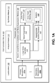
- FIG. 1 is a block diagram illustrating a communication device 102 with a multi-channel echo cancellation and noise suppression module 106.
- the communication device 102 may include a primary microphone 104a and one or more secondary microphones 104b that receive sound input from one or more sources (e.g., a loudspeaker 108, background noise, echo/echoes from a speaker/speakers (stereo/surround sound), etc.).
- sources e.g., a loudspeaker 108, background noise, echo/echoes from a speaker/speakers (stereo/surround sound), etc.
- Each of the microphones 104 may produce a signal or channel of audio that may be slightly different than one another.
- there may be two microphones 104 e.g., a primary microphone 104a and a secondary microphone 104b that produce two channels of audio, although any number of microphones 104 may be used.
- the microphones 104 and loudspeaker 108 may use additional modules (not shown) to process acoustic signals into digital audio and vice versa.
- the communication device 102 may include analog-to-digital converters, digital-to-analog converters, audio buffers, an automatic volume control module, etc.
- the communication device 102 may also include more than one loudspeaker 108.
- communication device refers to an electronic device that may be used to receive, externally play and/or optimize audio to and from a user.
- Examples of communication devices 102 include telephones, speaker phones, cellular phones, personal digital assistants (PDAs), handheld devices, wireless modems, laptop computers, personal computers, etc.
- a communication device 102 may alternatively be referred to as an access terminal, a mobile terminal, a mobile station, a remote station, a user terminal, a terminal, a subscriber unit, a subscriber station, a mobile device, a wireless device, a wireless communication device, a user equipment (UE) or some other similar terminology.
- PDAs personal digital assistants
- a communication device 102 may alternatively be referred to as an access terminal, a mobile terminal, a mobile station, a remote station, a user terminal, a terminal, a subscriber unit, a subscriber station, a mobile device, a wireless device, a wireless communication device, a user equipment (UE) or some other similar terminology.
- the communication device 102 may also include an analysis module 110 and a synthesis module 112 to deconstruct and reconstruct audio signals, respectively. This may allow other modules discussed herein to process the audio (e.g., perform echo cancellation and noise suppression).
- the analysis module 110 and synthesis module 112 may refer to finite impulse response filter (FIR) banks that decompose a wideband signal into sub-bands and reconstructs the sub-bands into a single band, respectively.
- FIR finite impulse response filter
- Echo cancellation (EC) and multi-microphone noise suppression (NS), such as beamforming or masking may be two distinct signal processing concepts, however their goals may converge with regard to acoustic echoes.
- linear echo cancellation may subtract an echo estimate from the desired signal based on reference information
- noise suppression may blindly remove undesired interference (e.g., echoes) within a microphone signal using spatial filtering.
- the communication device 102 may include a multi-channel echo cancellation and noise suppression module 106 with a linear echo canceller (LEC) 114, a noise suppressor (NS) 116 and an echo post-processor 118.
- LEC linear echo canceller
- NS noise suppressor
- the linear echo canceller 114 may perform linear echo cancellation for selected frequencies for the signals received from the microphones 104.
- the linear echo of the full band of frequencies received from the primary microphone 104a is cancelled while LEC is performed for only a set of low-band frequencies for the secondary (non-primary) microphones 104b.
- the frequencies selected for LEC on the secondary channels may correspond to the range of frequencies over which spatial processing in the noise suppressor is effective.
- the "primary microphone” may refer to the microphone 104a closest to a user's mouth. All non-primary microphones may be considered secondary microphones 104b.
- the noise suppressor 116 may perform spatial processing and noise suppression post-processing based on a noise reference from a spatial processor. In other words, the noise suppressor 116 may attenuate the echo as undesired interference based on spatial filtering.
- the echo post-processor 118 may perform non-linear echo post-processing by attenuating the non-linear echoes.
- the echo post-processor 118 may also perform non-linear echo clipping and comfort noise injection.
- the echo post-processor 118 may include an echo notch masking module 120.
- the echo notch masking module 120 may reduce echo in a noise-suppressed signal from the noise suppressor 116.
- the echo notch masking module 120 may perform amplitude suppression based on an echo direction of arrival (DOA) and speech likelihood information. Using the speech likelihood information, frequency bins with a high-likelihood for an echo direction of arrival (DOA) can be suppressed.
- DOA echo direction of arrival
- adaptive spatial processing used by a noise suppressor 116 adds echo from the secondary microphone 104b to the primary microphone 104a and the echo post-processor 118 may be blind to this. Since the echo post-processor 118 is blind to this echo, the echo post-processor 118 may not be able to cancel this added echo. This residual echo may be perceivable to the listener and highly annoying when there is almost little or no echo in the primary microphone 104a to begin with.
- the present systems and methods may provide the echo post-processor 118 with additional information that may be used with a non-linear echo model to cancel the residual echo.
- a spatial-processed echo estimate may be determined by a supplemental spatial processor 122. Therefore, the spatial processing performed by the supplemental spatial processor 122 on the echo estimate(s) from the linear echo canceller may replicate the processing done on linear echo-cleaned outputs by the noise suppressor 116. This may make the echo post-processor 118 aware of the spatial processing of the LEC 114 outputs (by the noise suppressor 116) so that the echo post-processor 118 does not add any echo in the primary microphone 104a.
- an echo estimate from a primary microphone 104a and at least one secondary microphone 104b may be used by the echo post-processor 118 to cancel non-linear echo.
- a selector 124 may select the echo estimate that is provided to the echo post-processor 118.
- the selector 124 may select one of the primary microphone echo estimate, the secondary microphone echo estimate(s) or the spatial-processed echo estimate.
- the selector 124 may scale the selected echo estimate.
- the selector 124 may also select a combination of the primary microphone echo estimate, the secondary microphone echo estimate(s) or the spatial-processed echo estimate. It should be noted that in the configuration illustrated in Figure 1 , the selector 124 is included in the echo post-processor 118. In another configuration, the selector 124 may be located outside the echo post-processor 118.
- the multi-channel echo cancellation and noise suppression module 106 may be implemented by a processor 101.
- different processors may be used to implement different components (e.g., one processor may perform linear echo cancellation, another processor may be used to perform noise suppression, another processor may be used to perform echo post-processing, and yet another processor may be used to perform supplemental spatial processing).
- FIG. 2 is a block diagram illustrating one configuration of a multi-channel echo cancellation and noise suppression module 206.
- the multi-channel echo cancellation and noise suppression module 206 may include a linear echo canceller 214, a noise suppressor 216 and an echo post-processor 218.
- the linear echo canceller 214 may be at the front of the processing chain, i.e., to avoid any non-linear processes and to avoid re-modeling/re-learning the rapid variations in the processing path due to the spatial processor 238.
- the linear echo canceller 214 may receive the primary audio channel from a primary microphone 204a and one or more secondary audio channels from one or more secondary microphones 204b. Since a loudspeaker 208 may play far-end speech 226 relatively close to the microphone(s) 204, compared to the desired talker, the microphone(s) 204 may see a near-end signal-to-echo ratio in the range of -5 to -12 dB. Thus, the full-band LEC and the sub-band LECs may be designed efficiently and in order to bring the residual echoes below the desired talker's level at all times for the spatial processor 238 to work optimally.
- the linear echo canceller 214 may use an acoustic echo cancelling (AEC) filter 228 to determine an echo estimate for each microphone 204 based on far-end speech 226.
- AEC acoustic echo cancelling
- Each AEC filter 228 may use a room transfer function to determine the echo estimate for each microphone channel.
- One AEC filter 228a may determine the echo estimate for the primary microphone (referred to as the primary microphone echo estimate ( ⁇ 1 ) 236a) based on a transfer function measured at the primary microphone 204a.
- another AEC filter 228b may determine the echo estimate for the secondary microphone (referred to as the secondary microphone echo estimate ( ⁇ 2 ) 236b) based on a transfer function measured at the secondary microphone 204b.
- the primary microphone echo estimate ( ⁇ 1 ) 236a may be subtracted from the primary microphone channel using an adder 234a.
- the secondary microphone echo estimate ( ⁇ 2 ) 236b may be subtracted from the secondary microphone channel using an adder 234b.
- the linear echo-cleaned primary microphone channel and the linear echo-cleaned secondary microphone channel may be passed to a spatial processor 238 in the noise suppressor (NS) 216.
- NS noise suppressor
- the present systems and methods may be used with any number of microphones 204.
- linear echo cancellation may be performed only in a selected range of low frequencies on the secondary channels.
- the spatial processing within the noise suppressor 216 may only be done for this selected range of frequencies.
- linear echo cancellation for the secondary channels may only be performed in the frequency range over which spatial processing is effective (using the sub-band LECs).
- Linear echo cancellation may be done on the entire band only for the primary channel (using the full-band LEC), so the higher frequencies of the primary microphone 204a survive the spatial processor 238 as shown in Figure 2 .
- the spatial processor 238 of the NS 216 may take the selected low frequencies of each microphone channel and produce a corresponding set of spatially processed low frequencies.
- Noise suppression post-processing may include non-linear, spectral-subtraction based processing where the noise reference from the spatial processing could serve as the unwanted component. Therefore, the noise suppression post-processor 240 may produce a noise-suppressed signal 262 and noise suppression gain 264 by suppressing noise in output of a linear echo cancellation of at least two microphone channels.
- non-linear echo processing would not be used in an echo control system, i.e., the linear echo canceller 214 would be sufficient to achieve echo-free full duplex conversation.
- the one or more linear adaptive filters used in an acoustic echo canceller (AEC) filter 228 in the linear echo canceller 214 may only remove linear echo.
- the linear echo canceller 214 may not be able to suppress non-linear echo components that are typically mixed with the linear echo. This remaining non-linear echo may be audible and may degrade the overall quality of communication.
- the adaptive filter used in an acoustic echo canceller (AEC) filter 228 to model the room response may be shorter than the true room response, thereby leaving some residual tail echo after the linear echo cancellation.
- AEC acoustic echo canceller
- typically a non-linear echo post-processor 218 may be employed.
- the echo post-processor 218 may receive the noise-suppressed signal channel data 262 from the noise suppressor 216 and remove the residual tail and/or non-linear echo.
- the full-band echo post-processor 254 may use a spectral subtraction-based scheme to remove any residual non-linear echo by using a model of the harmonic distortions created due to the loudspeaker 208.
- the full-band echo post-processor 254 may produce a non-linear echo-suppressed signal 268.
- a communication device 102 may include two or more microphones 204.
- the primary microphone 204a may be placed away from the loudspeaker 208 (e.g., on the bottom of the communication device 102).
- the secondary microphone 204b may be placed near the loudspeaker 208 (e.g., on the top of the communication device 102).
- the primary microphone 204a that is placed away from the loudspeaker 208 may have lower echo compared to the secondary microphone 204b that is placed closer to the loudspeaker 208. Therefore, the secondary microphone 204b may pick up significantly stronger echo.
- the linear echo canceller 214 may cancel the linear echo and provide the linear echo-suppressed signal(s) to the spatial processor 238 of the noise suppressor 216.
- the primary audio channel from the primary microphone 204a may have no echo left over, but the secondary audio channel from the secondary microphone 204b may have a significant amount of echo.
- the spatial processor 238 may add the residual echo from the secondary microphone 204b to the primary microphone 204a due to the way the spatial processing works by adding and subtracting signals. Spatial processing may remove ambient noise and preserve near-end user speech 232.
- the spatial-processed signal is then provided to the full-band noise suppression post-processor 240 to produce a noise-suppressed signal 262 and noise suppression gain 264 that are provided to the echo post-processor 218.
- the added echo may appear as part of the noise-suppressed signal 262 from the primary microphone 204a and the echo post-processor 218 may be blind to the added echo.
- a selected echo estimate 266 may be provided to the full-band echo post-processor 254.
- Multiple echo estimates may be received at a selector 224. It should be noted that in the configuration illustrated in Figure 2 , the selector 224 is included in the echo post-processor 218. In another configuration, the selector 224 may be located outside the echo post-processor 218. The selector 224 may select one of the multiple echo estimates and pass the selected echo estimate 266 to the full-band echo post-processor 254.
- One echo estimate that may be provided to the selector 224 is a spatial-processed echo estimate 252.
- the primary microphone echo estimate ( ⁇ 1 ) 236a and the secondary microphone echo estimate ( ⁇ 2 ) 236b may be spatially processed by a supplemental spatial processor 222 to produce the spatial-processed echo estimate 252.
- the spatial processing performed by the supplemental spatial processor 222 on the primary microphone echo estimate ( ⁇ 1 ) 236a and the secondary microphone echo estimate ( ⁇ 2 ) 236b may replicate the processing done on linear echo-cleaned outputs by the spatial processor 238 in the noise suppressor 216.
- the spatial-processed echo estimate 252 produced by the supplemental spatial processor 222 may be an estimate of the echo added by the spatial processor 238 in the noise suppressor 216.
- the primary microphone echo estimate ( ⁇ 1 ) 236a and the secondary microphone echo estimate ( ⁇ 2 ) 236b may be transformed into the frequency domain by a frequency transform module 242 before being passed to the echo post-processor 218 (by using a Fast Fourier Transform (FFT), for example).
- FFT Fast Fourier Transform
- the echo post-processor 218 may receive one of the multiple echo estimates for non-linear echo cancellation.
- the selector 224 may select one of the received echo estimates for processing by the full-band echo post-processor 254.
- the selector 224 may select the spatial-processed echo estimate 252, the primary microphone echo estimate ( ⁇ 1 ) 236a or the secondary microphone echo estimate ( ⁇ 2 ) 236b for non-linear echo cancellation.
- the selector 224 may determine the selected echo estimate 266 based on a maxima of the received echo estimates.
- the selector 224 may scale the selected echo estimate 266.
- the selected echo estimate 266 may also include a combination of signals. Selecting one of multiple echo estimates may include combining multiple echo estimates to produce a selected echo estimate 266. For example, two or more of the primary microphone echo estimate ( ⁇ 1 ) 236a, the secondary microphone echo estimate ( ⁇ 2 ) 236b and the spatial-processed echo estimate 252 may be combined in various ways. For instance, the selector 224 may directly combine the primary microphone echo estimate ( ⁇ 1 ) and a scaled or modified version of the secondary microphone echo estimate ( ⁇ 2 ). Alternatively, the selector 224 may also produce a signal that is a function of two or more of these signals, i.e.
- these functions may be maxima, addition, subtraction, scaling, average of these signals, average of the signal energies, etc.
- the selected echo estimate 266 may be used by the full-band echo post-processor 254 with a non-linear echo model for cancelling non-linear echo.
- the echo post-processor 218 may be aware of the spatial processing (by the spatial processor 238 in the noise suppressor 216) of the LEC outputs so that the echo post-processor 218 may cancel any residual echo in the primary microphone channel.
- the full-band echo post-processor 254 may perform spectral subtraction using the selected echo estimate 266 to cancel echo in the noise-suppressed signal 262.
- the full-band echo post-processor 254 may include an echo notch masking module 220 to further reduce echo in the noise-suppressed signal 262.
- the echo notch masking module 220 may perform amplitude suppression based on speech likelihood information 248 that indicates the likelihood of a specific beam to be dominated by echo or not.
- the spatial processor 238 may determine the speech likelihood information 248 based on an anglogram, which may indicate the likelihood per angle per frequency bin for target speech.
- the spatial processor 238 may determine various spatial beams based on the primary and secondary microphone channels. Each beam may be associated with a particular direction (e.g., angle). For each frame in time, a range of frequencies may be grouped in frequency bins. For each angle, the spatial processor 238 may determine an estimated speech likelihood for each frequency bin. Using the speech likelihood information 248, frequency bins that have a high-likelihood for an echo direction of arrival (DOA) can be suppressed.
- DOA echo direction of arrival
- the echo DOA may be determined based on the location of the one or more microphones 204 and the one or more loudspeakers 208. In one configuration, if the one or more loudspeakers 208 are fixed with respect to the communication device 102, then the echo DOA may be determined during a calibration stage. In another configuration, if the one or more loudspeakers 208 are non-fixed (e.g., auxiliary) with respect to the communication device 102, then the echo DOA may be determined in real-time when far-end activity is detected. The echo DOA may be expressed as an angle.
- the echo notch masking module 220 may determine a masking gain to apply to the noise-suppressed signal 262.
- the echo notch masking module 220 may selectively suppress frequency bins that are likely to include an echo signal.
- the echo notch masking module 220 may apply a masking window located based on the echo DOA with a certain margin around the echo DOA. If the direction of a frequency bin of the noise-suppressed signal 262 falls within the masking window, then the echo notch masking module 220 may apply a masking gain to the frequency bin to produce an echo-suppressed signal.
- the echo notch masking module 220 may be activated during far-end activity. For example, the echo notch masking module 220 may be activated upon receipt of a far-end flag 246 and may be deactivated upon receipt of a double-talk flag 244 or a near-end flag 250.
- the full-band non-linear echo clipper 256 may then further suppress any residual echo. Therefore, the non-linear echo clipper 256 may alleviate the burden on the spectral subtraction-based scheme (in the echo post-processor 218) in removing strong residual echoes and thereby improving full-duplex capabilities. These modules may keep track of the echo attenuation provided blindly by the full-band NS post-processor 240 and update their gain accordingly, thereby preventing excessive echo attenuation.
- the full-band non-linear echo clipper 256 may receive the non-linear echo-suppressed signal 268. In one configuration, the full-band non-linear echo clipper 256 may use the non-linear echo model produced by the echo post-processor 218.
- a full-band comfort noise injector 258 may undo the modulations applied to the noise floor due to these non-linear processes.
- far-end refers to something not in relative proximity to a communication device 102.
- near-end refers to something in relative proximity to the communication device 102.
- the speech of a user of the communication device 102 e.g., near-end user speech 232
- the speech of another person communicating remotely may generate a far-end signal.
- one or more flags may be generated based on characteristics of the audio channels. These flags may be used to adapt the processing carried out in the multi-channel echo cancellation and noise suppression module 106. Specifically, four different types of flags may be generated and used by the subsequent modules for optimal performance: clipping flags 260, a far-end flag 246, a double-talk flag 244 and a near-end flag 250.
- the clipping flags 260 may be generated within the linear echo canceller 214 based on the echo attenuation provided by the linear echo canceller 214.
- the clipping flags 260 may be used by the echo post-processor 218 for residual echo suppression. In speakerphone environments, acoustic echoes may be a major problem, and the desired talker-to-echo ratio may be on the order of -4 to -12 dB.
- the clipping flags 260 may be used in the full-band non-linear echo clipper 256 to further suppress the residual echo. These clipping flags 260 may be generated using the echo attenuation provided by the linear echo canceller 214.
- the echo attenuation provided by the linear echo canceller 214 is high, that may imply strong echo portions that are most likely echo-only periods. Thus, the residual signal after echo cancellation and noise suppression may be further suppressed. Since the primary channel survives the noise suppression scheme, the echo attenuation provided by the linear echo canceller 214 of the primary channel in the lower and higher bands may be used to determine values for two non-linear clipping flags 260 for the corresponding frequency bands.
- a far-end flag 246 may also be determined that indicates far-end voice activity.
- a simple energy-based voice activity detector (VAD) may be used to detect the far-end activity. Thresholds for far-end voice activity may be chosen at a higher end so that only relatively strong far-end speech 226 portions are detected. Specifically, it may be desirable to detect those portions of far-end speech 226 that may leave some residual echo after the linear echo cancellation.
- This binary far-end flag 246 may be used by the noise suppressor 216 to determine whether to learn the source position and to avoid accidentally learning in the direction of the echo as the desired source direction. In one configuration, the far-end flag 246 may be used to determine the double-talk flag 244 that is used to determine whether the spatial processor 238 should attempt to learn in the direction of a desired signal.
- the double-talk flag 244 may update the status of the linear echo canceller 214.
- the double-talk flag 244 may be high in true double-talk situations, i.e. true overlap of far-end and near-end speech periods.
- the double-talk flag 244 may also be high when the echo attenuation provided by the linear echo canceller 214 is very low. Therefore, the double-talk flag 244 may serve two different objectives. First, the double-talk flag 244 may prevent spatial processing and source learning by the spatial processor 238 during true double-talk periods, thereby preventing any undesirable near-end talker attenuation during such periods. Second, the double-talk flag 244 may also be high when the echo attenuation provided by the linear echo canceller 214 is minimal. Source learning may not be performed by the spatial processor 238 during such periods to prevent any accidental learning towards the relatively strong residual acoustic echoes.
- a near-end flag 250 may also be determined that indicates near-end voice activity.
- the near-end flag 250 may be used by the echo post-processor 218 to determine the aggressiveness of the non-linear echo post-processing.
- any double-talk detection flag 244 may serve as a near-end flag 250.
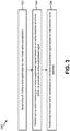
- Figure 3 is a flow diagram illustrating a method 300 for multi-channel echo cancellation and noise suppression.
- the method 300 may be performed by a communication device 102, e.g., as illustrated in Figure 1 .
- the communication device 102 may select 302 one of multiple echo estimates for non-linear echo cancellation.
- the communication device 102 may determine a primary microphone echo estimate ( ⁇ 1 ) 236a and a secondary microphone echo estimate ( ⁇ 2 ) 236b during linear echo cancellation of at least two microphone channels. This may include modeling a room response in an acoustic echo canceller (AEC) filter 228b for a primary microphone 204a and a secondary microphone 204b, determining the primary microphone echo estimate ( ⁇ 1 ) 236a based on the room response for the primary microphone 204a and determining the second microphone echo estimate ( ⁇ 2 ) 236b based on the room response for the secondary microphone 204b.
- AEC acoustic echo canceller
- the communication device 102 may spatial process the primary microphone echo estimate ( ⁇ 1 ) 236a and the secondary microphone echo estimate ( ⁇ 2 ) 236b to produce a spatial-processed echo estimate 252.
- the spatial processing may replicate the processing done on linear echo-cleaned outputs by a spatial processor 238 in a noise suppressor 216.
- the communication device 102 may select 302 one of the spatial-processed echo estimate 252, the primary microphone echo estimate ( ⁇ 1 ) 236a and the secondary microphone echo estimate ( ⁇ 2 ) 236b for non-linear echo cancellation.
- the communication device 102 may select 302 an echo estimate based on a maxima of the multiple echo estimates.
- the communication device 102 may also select 302 a combination of the multiple echo estimates to produce the selected echo estimate 266.
- One or more of the primary microphone echo estimate ( ⁇ 1 ) 236a, the secondary microphone echo estimate ( ⁇ 2 ) 236b and the spatial-processed echo estimate 252 may be adjusted or combined in various ways.
- the communication device 102 may scale the selected echo estimate 266.
- the communication device 102 may combine two or more echo estimates through addition, subtraction, scaling, averaging, etc.
- Linear echo cancellation may further include subtracting the primary microphone echo estimate ( ⁇ 1 ) 236a from a primary microphone channel to produce a linear echo-cleaned primary microphone channel and subtracting the secondary microphone echo estimate ( ⁇ 2 ) 236b from a secondary microphone channel to produce a linear echo-cleaned secondary microphone channel.
- the communication device 102 may produce a noise-suppressed signal 262 based on the linear echo-cleaned primary and secondary microphone channels.
- noise suppression may include spatially processing the linear echo-cleaned primary microphone channel and the linear echo-cleaned secondary microphone channel.
- Noise suppression post-processing may include non-linear, spectral-subtraction based processing where a noise reference from the spatial processing serves as the unwanted component.
- the communication device 102 may perform 304 echo notch masking on a noise-suppressed signal 262 based on an echo direction of arrival (DOA) to produce an echo-suppressed signal.
- Echo notch masking may include amplitude suppression based on speech likelihood information 248 that indicates the likelihood of a specific beam to be dominated by echo or not.
- the communication device 102 may calculate speech likelihood information 248 during spatial processing of the linear echo-cleaned primary microphone channel and the linear echo-cleaned secondary microphone channel.
- the speech likelihood information 248 may indicate the likelihood per angle per frequency bin for speech.
- the spatial processing may determine an estimated direction for each frequency bin. Using the speech likelihood information 248, frequency bins that have a high-likelihood for an echo DOA can be suppressed.
- the echo DOA may be determined based on the location of the one or more microphones 204 and the one or more loudspeakers 208. In one configuration, if the one or more loudspeakers 208 are fixed with respect to the communication device 102, then the echo DOA may be determined during a calibration stage. In another configuration, if the one or more loudspeakers 208 are non-fixed (e.g., auxiliary) with respect to the communication device 102, then the echo DOA may be determined in real-time when far-end activity is detected.
- the communication device 102 may determine a masking gain to apply to the noise-suppressed signal 262 to produce an echo-suppressed signal.
- the communication device 102 may selectively suppress frequency bins that are likely to include an echo signal.
- the communication device 102 may apply a masking window located based on the echo DOA with a certain margin around the echo DOA. If the direction (e.g., angle) of a frequency bin of the noise-suppressed signal 262 falls within the masking window, then the communication device 102 may apply a masking gain to the frequency bin to produce the echo-suppressed signal.
- the communication device 102 may perform 306 non-linear echo cancellation on the echo-suppressed signal based, at least in part, on the selected echo estimate 266.
- the non-linear echo cancellation may include using a non-linear echo model based on the selected echo estimate 266 and the echo-suppressed signal.
- the communication device 102 may include a non-linear echo model of the harmonic distortions created due to the loudspeaker 208.
- the communication device 102 may apply the echo-suppressed signal to the non-linear model to obtain a non-linear echo estimate.
- the communication device 102 may use a spectral subtraction-based scheme to remove any residual non-linear echo.
- the communication device 102 may cancel any residual echo that may have been added by spatial processing during noise suppression by using the selected echo estimate 266.
- the communication device 102 may perform spectral subtraction using the selected echo estimate 266 to cancel echo in the noise-suppressed signal 262.
- Figure 4 is a block diagram of a full-band echo post-processor 454 configured for multi-channel echo cancellation and noise suppression.
- the full-band echo post-processor 454 may be included in an echo post-processor 118 of a communication device 102, as described above in connection with Figure 1 .
- the full-band echo post-processor 454 may include an echo notch masking module 420 and a full-band echo post-processing module 470.
- the echo notch masking module 420 may receive a noise-suppressed signal 462 (from a noise suppressor 216, for example).
- the noise-suppressed signal 462 may be produced as described above in connection with Figure 2 .
- the noise suppressor 216 may spatially process a linear echo-cleaned primary microphone channel and a linear echo-cleaned secondary microphone channel.
- the noise suppressor 216 may then perform noise suppression post-processing that may include non-linear, spectral-subtraction based processing where a noise reference from the spatial processing serves as the unwanted component.
- the echo notch masking module 420 may perform amplitude suppression based on speech likelihood information 448 that indicates the likelihood of a specific beam to be dominated by echo or not.
- echo notch masking module 420 may receive the speech likelihood information 448 from a spatial processor 238, as described above in connection with Figure 2 .
- the speech likelihood information 448 may indicate the likelihood per angle per frequency bin for target speech.
- An echo direction of arrival (DOA) 478 may be determined based on the location of the one or more microphones 204 and the one or more loudspeakers 208. In one configuration, the echo DOA 478 may be determined by playing back only the echo signal. For a fixed loudspeaker 108, the echo DOA 478 may be determined during a calibration stage, as described below in connection with Figure 5 . For one or more auxiliary loudspeakers 108, the echo DOA 478 may be determined in real-time when far-end activity is detected, as described below in connection with Figure 6 . The echo DOA 478 may be expressed as an angle. Speech that has a high likelihood at the echo DOA 478 may be assumed to be echo.
- the echo notch masking module 420 may determine a masking gain to apply to the noise-suppressed signal 462.
- the echo notch masking module 420 may selectively suppress frequency bins that are likely to include an echo signal.
- a likelihood threshold may be set (e.g., 0.9*theoretical maximum likelihood). If the likelihood associated with a frequency bin is above the likelihood threshold, then a masking gain calculation may be applied to that frequency bin.
- the echo notch masking module 420 may apply a masking window located based on the echo DOA 478 with a certain margin around the echo DOA 478. If the direction of a frequency bin of the noise-suppressed signal 462 falls within the masking window, then the echo notch masking module 420 may apply a masking gain to the frequency bin to produce an echo-suppressed signal 474.
- the echo notch masking module 420 may be activated during far-end activity.
- the echo notch masking module 420 may be activated upon receipt of a far-end flag 446 and may be deactivated upon receipt of a double-talk flag 444a or a near-end flag 450a.
- the echo notch masking module 420 may provide the echo-suppressed signal 474 and noise and echo suppression gain 472 to the full-band echo post-processing module 470 for non-linear echo cancellation. This may be accomplished as described in connection with Figure 2 .
- the full-band echo post-processing module 470 may perform non-linear model-based echo cancellation on the echo-suppressed signal 474 based on the selected echo estimate 466 to produce a non-linear echo-suppressed signal 468.
- the full-band echo post-processing module 470 may apply smoothing based on the noise and echo suppression gain 472 to avoid musical noise artifacts.
- the noise and echo suppression gain 472 may include the masking gain in addition to the noise suppression gain 464.
- the noise and echo suppression gain 472 may be passed to the full-band echo post-processing module 470 to control the aggressiveness of the post-processing according to the gain already applied to the echo-suppressed signal 474. If the gain applied to the echo-suppressed signal 474 is already aggressive, then the full-band echo post-processing module 470 may apply a less aggressive gain (or vice versa), which may achieve more consistent echo cancellation and noise suppression.
- a near-end flag 450b or double-talk flag 444b may be used by the full-band echo post-processing module 470 to determine the aggressiveness of the non-linear echo post-processing. In one configuration, any double-talk flag 444b may serve as a near-end flag 450b.
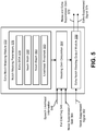
- FIG. 5 is a block diagram of one configuration of an echo notch masking module 520.
- the echo notch masking module 520 may be included in a full-band echo post-processor 454, as described above in connection with Figure 4 .
- the echo notch masking module 520 illustrated in Figure 5 may be used for a fixed-loudspeaker scenario.
- the loudspeaker 108 position may be fixed on the communication device 102 in typical handset operation.
- the echo notch masking module 520 may selectively suppress frequency bins in a noise-suppressed signal 562 that are likely to include an echo signal.
- the echo notch masking module 520 may include notch masking parameters 576.
- the echo notch masking module 520 may determine the fixed echo DOA 578 during a calibration stage by playing back only an echo signal. In one configuration, this may be accomplished by performing an anglogram calculation (by a spatial processor 238).
- the echo DOA 578 may be obtained ahead of run-time and stored in the notch masking parameters 576. Because the loudspeaker 108 position is fixed on the communication device 102, the echo DOA 578 is also fixed. In one configuration, the echo DOA 578 may be expressed as an angle.
- the echo notch masking module 520 may determine a notch width 580 and a notch depth 582.
- the notch width 580 may be a margin that forms a masking window.
- the notch width 580 may be a number of degrees from the echo DOA 578 that may be included in the notch masking calculation.
- the notch width 580 may be plus or minus 10 degrees from the echo DOA 478. It should be noted that other values for the notch width 580 may be utilized.
- the notch depth 582 may be the amount of masking gain that may be applied to a frequency bin at the echo DOA 578.
- the echo notch masking module 520 may apply linear suppression in between the notch width 580.
- a masking gain calculation module 584 may receive speech likelihood information 548 for a frame.
- the speech likelihood information 548 may indicate the likelihood per angle per frequency bin for target speech.
- the speech likelihood information 548 may be determined by performing an anglogram calculation by the spatial processor 238.
- the masking gain calculation module 584 may apply a likelihood threshold 583 to the frequency bins for each angle to determine whether to perform notch masking on a frequency bin. If the speech likelihood for a frequency bin is greater than the likelihood threshold 583, then the masking gain calculation module 584 may calculate the masking gain for that frequency bin based on the notch width 580 and notch depth 582.
- the echo notch masking module 520 may notch out the echo signal corresponding to the echo DOA 578 for each echo beam to suppress echo leakage.
- the masking gain calculation module 584 may determine an amount to suppress the noise-suppressed signal 562 within the masking window. If the angle of a frequency bin is outside the notch masking window (defined by the echo DOA 578 and the notch width 580), then no masking gain is applied (e.g., a 0 dB unity gain may be applied). However, if the angle of a frequency bin is within the masking window, then the masking gain for the frequency bin may be determined based on the notch depth 582. The masking gain calculation module 584 may perform notch masking for each frame. An example of notch masking is illustrated in Figure 7 .
- the noise-suppressed signal 562 represents a beam-nullformed output from the NS module 216 to suppress a near-end interferer.
- the noise suppression gain 564 represents the calculated NS post-processing gain. If there is no far-end activity, the echo notch masking output module 586 becomes a simple post-processing scheme for applying the noise suppression gain 564. If there is far-end activity, then the additional post-processing gain (e.g., a masking gain for the echo) as determined by the masking gain calculation module 584 may be applied together with the existing noise suppression gain 564.
- a final post-processing gain e.g., the noise and echo suppression gain 572
- a minimum suppression gain constraint may be applied. The minimum suppression gain may be selected from the minimum of the noise suppression gain 564, masking gain and the combined noise and echo suppression gain 572.
- the echo notch masking output module 586 may apply the masking gain to the noise-suppressed signal 562. For example, selected frequency bins may be suppressed according to the determined masking gain to produce the echo-suppressed signal 574. This may further suppress residual echo in the noise-suppressed signal 562.
- the echo notch masking output module 586 may also output the noise and echo suppression gain 572, which may include the masking gain and the noise suppression gain 564.
- the echo notch masking module 520 may be activated during far-end activity.
- the echo notch masking module 520 may be activated upon receipt of a far-end flag 546 at the masking gain calculation module 584.
- FIG. 6 is a block diagram of another configuration of an echo notch masking module 620.
- the echo notch masking module 620 may be included in a full-band echo post-processor 454, as described above in connection with Figure 4 .
- the echo notch masking module 620 illustrated in Figure 6 may be used for a non-fixed loudspeaker scenario.
- the one or more loudspeakers 108 may be auxiliary loudspeakers 108. This configuration may be used with an array of loudspeakers 108 that may be attached to the communication device 102 (during teleconferencing, for instance).
- auxiliary loudspeakers 108 may connect to the communication device 102 when there are alternative devices (e.g., a TV) that may communicate with the communication device 102.
- the echo DOA 678 may be time-varying, as the microphone 104 positions change relative to the one or more loudspeakers 108. Therefore, the echo notch masking module 620 may include an echo DOA estimation module 688 to determine the echo DOA 678 during run-time. This may be accomplished as described above in connection with Figure 5 , but instead of determining the echo DOA 678 once during calibration, the echo DOA estimation module 688 may determine the echo DOA 678 on a frame-by-frame basis, when far-end activity is detected (as indicated by a far-end flag 646a). In one configuration, the echo DOA estimation module 688 may be deactivated upon receipt of a near-end flag 650 or a double-talk flag 644.
- the echo notch masking module 620 may determine whether a user is using in-device loudspeaker 108 or an auxiliary loudspeaker 108.
- the echo notch masking module 620 may receive an auxiliary loudspeaker mode flag 689 upon activation of an auxiliary path for the auxiliary loudspeaker 108.
- the echo DOA estimation module 688 may determine the echo DOA 678 based on speech likelihood information 648 for a frame (obtained from a spatial processor 238).
- the spatial processor 238 may perform an anglogram calculation by playing back an echo signal to obtain the speech likelihood information 648.
- the echo notch masking module 620 may include notch masking parameters 676. Upon determining the echo DOA 678, the echo notch masking module 620 may determine a notch width 680 and a notch depth 682, as described above in connection with Figure 5 . The echo notch masking module 620 may also set a likelihood threshold 683.
- a masking gain calculation module 684 may receive the speech likelihood information 648.
- the speech likelihood information 648 may indicate the likelihood per angle per frequency bin for target speech.
- the masking gain calculation module 684 may determine the masking gain as described above in connection with Figure 5 .
- the masking gain calculation module 684 may determine the masking gain when a far-end flag 646b indicates far-end activity.
- the masking gain calculation module 684 may consider the noise suppression gain 664 when determining the aggressiveness of the masking gain. This may be accomplished as described above in connection with Figure 5 .
- the echo notch masking output module 686 may apply the masking gain to the noise-suppressed signal 662. For example, selected frequency bins may be suppressed according to the determined masking gain to produce the echo-suppressed signal 674.
- the echo notch masking output module 686 may also output the noise and echo suppression gain 672, which may include the masking gain and the noise suppression gain 664.
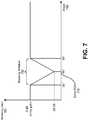
- Figure 7 is a graph depicting one configuration of echo notch masking.
- the echo notch masking may be performed by an echo notch masking module 120.
- Figure 7 shows the masking gain 791 that may be applied for various angles 790.
- a spatial processor 238 may determine various spatial beams based on primary and secondary microphone channels. Each beam may be associated with a particular direction (e.g., angle 790). For each frame in time, a range of frequencies may be grouped in frequency bins. An estimated speech likelihood for each frequency bin may be determined for each angle 790. Frequency bins with a high-likelihood (e.g., above a likelihood threshold 583) to be within a certain margin of an echo DOA 778 may be suppressed.
- a high-likelihood e.g., above a likelihood threshold 583
- an echo DOA 778 is determined to be 45 degrees.
- the echo DOA 778 may be determined by performing an anglogram calculation during spatial processing, as described above in connection with Figure 5 .
- the notch width 580 of the masking window 792 is 20 degrees. Therefore, frequency bins with an angle 790 between 35 degrees and 55 degrees may be suppressed by a masking gain 791. Frequency bins with an angle 790 outside the masking window 792 will have a unity gain of 0 dB.
- the masking window 792 may be located based on the echo DOA 778.
- the masking window 792 is centered on the echo DOA 778, with a 10 degree margin on either side of the echo DOA 778.
- the masking window 792 need not be centered on the echo DOA 778 (e.g., the margins on either side of the echo DOA 778 may be different).
- the masking gain 791 is -20 dB.
- the maximum masking gain 791 may be referred to as the notch depth 582.
- the masking gain 791 varies linearly within the masking window 792. In another configuration, the masking gain 791 may vary non-linearly within the masking window 792.
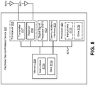
- FIG 8 illustrates certain components that may be included within an electronic device/wireless device 802.
- the electronic device/wireless device 802 may be an access terminal, a mobile station, a user equipment (UE), a base station, an access point, a broadcast transmitter, a node B, an evolved node B, etc., such as the communication device 102 illustrated in Figure 1 .
- the electronic device/wireless device 802 includes a processor 801.
- the processor 801 may be a general purpose single- or multi-chip microprocessor (e.g., an Advanced RISC (Reduced Instruction Set Computer) Machine (ARM) processor), a special purpose microprocessor (e.g., a digital signal processor (DSP)), a microcontroller, a programmable gate array, etc.
- ARM Advanced RISC
- DSP digital signal processor
- the processor 801 may be referred to as a central processing unit (CPU). Although just a single processor 801 is shown in the electronic device/wireless device 802 of Figure 8 , in an alternative configuration, a combination of processors (e.g., an ARM and DSP) could be used.
- processors e.g., an ARM and DSP
- the electronic device/wireless device 802 also includes memory 809.
- the memory 809 may be any electronic component capable of storing electronic information.
- the memory 809 may be embodied as random access memory (RAM), read-only memory (ROM), magnetic disk storage media, optical storage media, flash memory devices in RAM, on-board memory included with the processor, erasable programmable read-only memory (EPROM), electrically erasable PROM (EEPROM), registers and so forth, including combinations thereof.
- Data 813a and instructions 811a may be stored in the memory 809.
- the instructions 811a may be executable by the processor 801 to implement the methods disclosed herein. Executing the instructions 811a may involve the use of the data 813a that is stored in the memory 809. When the processor 801 executes the instructions 811a, various portions of the instructions 811b may be loaded onto the processor 801, and various pieces of data 813b may be loaded onto the processor 801.
- the electronic device/wireless device 802 may also include a transmitter 817 and a receiver 819 to allow transmission and reception of signals to and from the electronic device/wireless device 802.
- the transmitter 817 and receiver 819 may be collectively referred to as a transceiver 805.
- Multiple antennas 807a-n may be electrically coupled to the transceiver 805.
- the electronic device/wireless device 802 may also include (not shown) multiple transmitters, multiple receivers, multiple transceivers and/or additional antennas.
- the electronic device/wireless device 802 may include a digital signal processor (DSP) 823.
- the electronic device/wireless device 802 may also include a communications interface 825.
- the communications interface 825 may allow a user to interact with the electronic device/wireless device 802.
- the various components of the electronic device/wireless device 802 may be coupled together by one or more buses, which may include a power bus, a control signal bus, a status signal bus, a data bus, etc.
- buses may include a power bus, a control signal bus, a status signal bus, a data bus, etc.
- the various buses are illustrated in Figure 8 as a bus system 821.
- OFDMA Orthogonal Frequency Division Multiple Access
- SC-FDMA Single-Carrier Frequency Division Multiple Access
- An OFDMA system utilizes orthogonal frequency division multiplexing (OFDM), which is a modulation technique that partitions the overall system bandwidth into multiple orthogonal sub-carriers. These sub-carriers may also be called tones, bins, etc. With OFDM, each subcarrier may be independently modulated with data.
- OFDM orthogonal frequency division multiplexing
- An SC-FDMA system may utilize interleaved FDMA (IFDMA) to transmit on sub-carriers that are distributed across the system bandwidth, localized FDMA (LFDMA) to transmit on a block of adjacent sub-carriers, or enhanced FDMA (EFDMA) to transmit on multiple blocks of adjacent sub-carriers.
- IFDMA interleaved FDMA
- LFDMA localized FDMA
- EFDMA enhanced FDMA
- modulation symbols are sent in the frequency domain with OFDM and in the time domain with SC-FDMA.
- determining encompasses a wide variety of actions and, therefore, “determining” can include calculating, computing, processing, deriving, investigating, looking up (e.g., looking up in a table, a database or another data structure), ascertaining and the like. Also, “determining” can include receiving (e.g., receiving information), accessing (e.g., accessing data in a memory) and the like. Also, “determining” can include resolving, selecting, choosing, establishing and the like.
- processor should be interpreted broadly to encompass a general purpose processor, a central processing unit (CPU), a microprocessor, a digital signal processor (DSP), a controller, a microcontroller, a state machine, and so forth. Under some circumstances, a “processor” may refer to an application specific integrated circuit (ASIC), a programmable logic device (PLD), a field programmable gate array (FPGA), etc.
- ASIC application specific integrated circuit
- PLD programmable logic device
- FPGA field programmable gate array
- processor may refer to a combination of processing devices, e.g., a combination of a DSP and a microprocessor, a plurality of microprocessors, one or more microprocessors in conjunction with a DSP core, or any other such configuration.
- memory should be interpreted broadly to encompass any electronic component capable of storing electronic information.
- the term memory may refer to various types of processor-readable media such as random access memory (RAM), read-only memory (ROM), non-volatile random access memory (NVRAM), programmable read-only memory (PROM), erasable programmable read-only memory (EPROM), electrically erasable PROM (EEPROM), flash memory, magnetic or optical data storage, registers, etc.
- RAM random access memory
- ROM read-only memory
- NVRAM non-volatile random access memory
- PROM programmable read-only memory
- EPROM erasable programmable read-only memory
- EEPROM electrically erasable PROM
- flash memory magnetic or optical data storage, registers, etc.
- instructions and “code” should be interpreted broadly to include any type of computer-readable statement(s).
- the terms “instructions” and “code” may refer to one or more programs, routines, sub-routines, functions, procedures, etc.
- “Instructions” and “code” may comprise a single computer-readable statement or many computer-readable statements.
- a computer-readable medium or “computer-program product” refers to any tangible storage medium that can be accessed by a computer or a processor.
- a computer-readable medium may comprise RAM, ROM, EEPROM, CD-ROM or other optical disk storage, magnetic disk storage or other magnetic storage devices, or any other medium that can be used to carry or store desired program code in the form of instructions or data structures and that can be accessed by a computer.
- Disk and disc includes compact disc (CD), laser disc, optical disc, digital versatile disc (DVD), floppy disk and Blu-ray® disc where disks usually reproduce data magnetically, while discs reproduce data optically with lasers.
- the methods disclosed herein comprise one or more steps or actions for achieving the described method.
- the method steps and/or actions may be interchanged with one another without departing from the scope of the claims.
- the order and/or use of specific steps and/or actions may be modified without departing from the scope of the claims.
- modules and/or other appropriate means for performing the methods and techniques described herein can be downloaded and/or otherwise obtained by a device.
- a device may be coupled to a server to facilitate the transfer of means for performing the methods described herein.
- various methods described herein can be provided via a storage means (e.g., random access memory (RAM), read-only memory (ROM), a physical storage medium such as a compact disc (CD) or floppy disk, etc.), such that a device may obtain the various methods upon coupling or providing the storage means to the device.
- RAM random access memory
- ROM read-only memory
- CD compact disc
- floppy disk floppy disk
Landscapes
- Engineering & Computer Science (AREA)
- Signal Processing (AREA)
- Physics & Mathematics (AREA)
- Acoustics & Sound (AREA)
- Cable Transmission Systems, Equalization Of Radio And Reduction Of Echo (AREA)
- Telephone Function (AREA)
- Circuit For Audible Band Transducer (AREA)
Claims (15)
- Procédé d'annulation d'écho à canaux multiples et de suppression de bruit, comprenant :sélectionner (302) une estimation d'écho pour une annulation d'écho non linéaire ;effectuer (304) un masquage de filtre réjecteur de bande sur un signal à bruit supprimé sur la base d'une direction d'arrivée d'écho (DOA) pour produire un signal à écho supprimé, le signal à bruit supprimé étant reçu d'une sortie d'annulation d'écho linéaire d'au moins deux canaux de microphones, le masquage de filtre réjecteur de bande comprenant le fait de:supprimer le signal à bruit supprimé sur un distribution angulaire sur la base, en partie au moins, de la direction d'arrivée d'écho (DOA), etappliquer un gain de masquage à au moins une gamme de fréquence sur la base de la direction d'arrivée d'écho (DOA) ; eteffectuer (306) une annulation d'écho non linéaire sur le signal à écho supprimé sur la base, en partie au moins, de l'estimation d'écho sélectionnée.
- Procédé selon la revendication 1, dans lequel l'estimation d'écho est l'une d'entre une estimation d'écho traitée spatialement, une estimation d'écho de microphone primaire ou une estimation d'écho de microphone secondaire.
- Procédé selon la revendication 1, dans lequel sélectionner l'estimation d'écho comprend sélectionner un maximum de multiples estimations d'écho; et/ou dans lequel sélectionner l'estimation d'écho comprend combiner de multiples estimations d'écho pour produire l'estimation d'écho sélectionnée.
- Procédé selon la revendication 1, dans lequel appliquer le gain de masquage à au moins une gamme de fréquence est aussi basé sur une probabilité de voix.
- Procédé selon la revendication 1, dans lequel effectuer l'annulation d'écho non linéaire comprend utiliser un modèle non linéaire d'écho sur la base de l'estimation d'écho sélectionnée et du signal à écho supprimé.
- Produit de programme informatique pour annulation d'écho à canaux multiples et suppression de bruit, comprenant un support non transitoire lisible par ordinateur ayant des instructions dessus, les instructions comprenant :du code pour faire qu'un dispositif de communication sélectionne une estimation d'écho pour annulation d'écho non linéaire ;du code pour faire que le dispositif de communication effectue un masquage de filtre réjecteur de bande sur un signal à bruit supprimé sur la base d'une direction d'arrivée d'écho (DOA) afin de produire un signal à écho supprimé, le signal à bruit supprimé tant reçu d'une sortie de l'annulation d'écho linéaire d'au moins deux canaux de microphones, le masquage de filtre réjecteur de bande comprenant le fait de :supprimer le signal à bruit supprimé sur une distribution angulaire sur la base, en partie au moins, de la direction d'arrivée d'écho (DOA), etappliquer un gain de masquage à au moins une gamme de fréquence sur la base de la direction d'arrivée d'écho (DOA) ; etdu code pour faire que le dispositif de communication effectue une annulation d'écho non linéaire sur le signal à écho supprimé sur la base, en partie au moins, de l'estimation d'écho sélectionnée.
- Produit de programme informatique selon la revendication 6, dans lequel l'annulation d'écho linéaire comprend :du code pour faire que le dispositif de communication soustraie une estimation d'écho de microphone primaire d'un canal de microphone primaire ; etdu code pour faire que le dispositif de communication soustraie une estimation d'écho de microphone secondaire d'un canal de microphone secondaire.
- Produit de programme informatique selon la revendication 6, comprenant en outre du code pour faire que le dispositif de communication traite spatialement une estimation d'écho de microphone primaire et une estimation d'écho de microphone secondaire pour produire une estimation d'écho traitée spatialement.
- Produit de programme informatique selon la revendication 8, dans lequel le code pour faire que le dispositif de communication traite spatialement reproduit le traitement spatial qui est effectué en faisant que le dispositif de communication supprime le bruit dans une sortie de l'annulation d'écho linéaire.
- Produit de programme informatique selon la revendication 8, dans lequel du code pour faire que le dispositif de communication détermine l'estimation d'écho d'un microphone primaire et l'estimation d'écho d'un microphone secondaire, comprend :du code pour faire que le dispositif de communication modélise une réponse de salle dans un filtre annuleur d'écho acoustique (AEC) pour un microphone primaire et un microphone secondaire ;du code pour faire que le dispositif de communication détermine l'estimation d'écho du microphone primaire sur la base de la réponse de salle pour le microphone primaire ; etdu code pour faire que le dispositif de communication détermine l'estimation d'écho du microphone secondaire sur la base de la réponse de salle pour le microphone secondaire.
- Produit de programme informatique selon la revendication 8, dans lequel l'estimation d'écho du microphone primaire et l'estimation d'écho du microphone secondaire sont déterminées pendant l'annulation d'écho linéaire.
- Dispositif de communication pour annulation d'écho à canaux multiples et suppression de bruit, comprenant :un moyen pour sélectionner une estimation d'écho pour annulation d'écho non linéaire ;un moyen pour effectuer un masquage de filtre réjecteur de bande sur un signal à bruit supprimé sur la base d'une direction d'arrivée d'écho (DOA) pour produire un signal à écho supprimé, le signal à bruit supprimé étant reçu d'une sortie d'une annulation d'écho linéaire d'au moins deux canaux de microphones, le masquage de filtre réjecteur de bande comprenant le fait de :supprimer le signal à bruit supprimé sur une distribution angulaire sur la base, en partie au moins, de la direction d'arrivée d'écho (DOA), etappliquer un gain de masquage à au moins une gamme de fréquence sur la base de la direction d'arrivée d'écho (DOA) ; etun moyen pour effectuer une annulation d'écho non linéaire sur le signal à écho supprimé sur la base, en partie au moins, de l'estimation d'écho sélectionnée.
- Dispositif de communication selon la revendication 12, dans lequel la direction d'arrivée d'écho (DOA) est déterminée sur la base d'un emplacement d'un ou de plusieurs microphones et d'un ou de plusieurs haut-parleurs.
- Dispositif de communication selon la revendication 12, dans lequel la direction d'arrivée d'écho (DOA) est déterminée durant un stade d'étalonnage ; et/ou dans lequel la direction d'arrivée d'écho (DOA) est déterminée en temps réel lorsqu'une activité à une extrémité distante est détectée.
- Dispositif de communication selon la revendication 12, dans lequel appliquer le gain de masquage à au moins une gamme de fréquence est aussi basé sur une probabilité de voix ;
dans lequel des instructions exécutables pour déterminer le gain de masquage comprennent de préférence des instructions exécutables pour :appliquer une fenêtre de masquage située sur la base de la direction d'arrivée d'écho (DOA) ; etdéterminer un degré auquel supprimer le signal à bruit supprimé dans la fenêtre de masquage ; et/oudans lequel les instructions exécutables pour effectuer le masquage de filtre réjecteur de bande sont de préférence basées en outre sur une indication de parole à une extrémité distante.
Applications Claiming Priority (3)
| Application Number | Priority Date | Filing Date | Title |
|---|---|---|---|
| US201361819423P | 2013-05-03 | 2013-05-03 | |
| US14/156,292 US9936290B2 (en) | 2013-05-03 | 2014-01-15 | Multi-channel echo cancellation and noise suppression |
| PCT/US2014/035190 WO2014179135A1 (fr) | 2013-05-03 | 2014-04-23 | Annulation d'écho à canaux multiples et suppression du bruit |
Publications (2)
| Publication Number | Publication Date |
|---|---|
| EP2992668A1 EP2992668A1 (fr) | 2016-03-09 |
| EP2992668B1 true EP2992668B1 (fr) | 2018-02-21 |
Family
ID=51841451
Family Applications (1)
| Application Number | Title | Priority Date | Filing Date |
|---|---|---|---|
| EP14726292.7A Not-in-force EP2992668B1 (fr) | 2013-05-03 | 2014-04-23 | Annulation d'écho à canaux multiples et suppression du bruit |
Country Status (6)
| Country | Link |
|---|---|
| US (1) | US9936290B2 (fr) |
| EP (1) | EP2992668B1 (fr) |
| JP (1) | JP2016518628A (fr) |
| KR (1) | KR20160003844A (fr) |
| CN (1) | CN105144674B (fr) |
| WO (1) | WO2014179135A1 (fr) |
Families Citing this family (88)
| Publication number | Priority date | Publication date | Assignee | Title |
|---|---|---|---|---|
| US9357080B2 (en) * | 2013-06-04 | 2016-05-31 | Broadcom Corporation | Spatial quiescence protection for multi-channel acoustic echo cancellation |
| GB2525051B (en) | 2014-09-30 | 2016-04-13 | Imagination Tech Ltd | Detection of acoustic echo cancellation |
| GB2527865B (en) * | 2014-10-30 | 2016-12-14 | Imagination Tech Ltd | Controlling operational characteristics of an acoustic echo canceller |
| US9516159B2 (en) * | 2014-11-04 | 2016-12-06 | Apple Inc. | System and method of double talk detection with acoustic echo and noise control |
| US9769587B2 (en) | 2015-04-17 | 2017-09-19 | Qualcomm Incorporated | Calibration of acoustic echo cancelation for multi-channel sound in dynamic acoustic environments |
| US9554207B2 (en) | 2015-04-30 | 2017-01-24 | Shure Acquisition Holdings, Inc. | Offset cartridge microphones |
| US9565493B2 (en) | 2015-04-30 | 2017-02-07 | Shure Acquisition Holdings, Inc. | Array microphone system and method of assembling the same |
| US9407989B1 (en) | 2015-06-30 | 2016-08-02 | Arthur Woodrow | Closed audio circuit |
| EP3398355A1 (fr) * | 2015-12-29 | 2018-11-07 | Otis Elevator Company | Système de communication d'ascenseur acoustique et procédé de réglage d'un tel système |
| US9653060B1 (en) * | 2016-02-09 | 2017-05-16 | Amazon Technologies, Inc. | Hybrid reference signal for acoustic echo cancellation |
| US9659555B1 (en) * | 2016-02-09 | 2017-05-23 | Amazon Technologies, Inc. | Multichannel acoustic echo cancellation |
| US10509626B2 (en) | 2016-02-22 | 2019-12-17 | Sonos, Inc | Handling of loss of pairing between networked devices |
| US10264030B2 (en) | 2016-02-22 | 2019-04-16 | Sonos, Inc. | Networked microphone device control |
| US9820039B2 (en) | 2016-02-22 | 2017-11-14 | Sonos, Inc. | Default playback devices |
| US10095470B2 (en) | 2016-02-22 | 2018-10-09 | Sonos, Inc. | Audio response playback |
| CN105788607B (zh) * | 2016-05-20 | 2020-01-03 | 中国科学技术大学 | 应用于双麦克风阵列的语音增强方法 |
| US9978390B2 (en) | 2016-06-09 | 2018-05-22 | Sonos, Inc. | Dynamic player selection for audio signal processing |
| TWI579833B (zh) * | 2016-06-22 | 2017-04-21 | 瑞昱半導體股份有限公司 | 信號處理裝置與信號處理方法 |
| US10134399B2 (en) | 2016-07-15 | 2018-11-20 | Sonos, Inc. | Contextualization of voice inputs |
| US10115400B2 (en) | 2016-08-05 | 2018-10-30 | Sonos, Inc. | Multiple voice services |
| US10181323B2 (en) | 2016-10-19 | 2019-01-15 | Sonos, Inc. | Arbitration-based voice recognition |
| US10264116B2 (en) * | 2016-11-02 | 2019-04-16 | Nokia Technologies Oy | Virtual duplex operation |
| US10367948B2 (en) | 2017-01-13 | 2019-07-30 | Shure Acquisition Holdings, Inc. | Post-mixing acoustic echo cancellation systems and methods |
| JP2018186494A (ja) * | 2017-03-29 | 2018-11-22 | ジーエヌ ヒアリング エー/エスGN Hearing A/S | 適応型サブバンドビームフォーミングを用いた聴覚装置と関連する方法 |
| EP3641337A4 (fr) * | 2017-06-12 | 2021-01-13 | Yamaha Corporation | Dispositif de traitement de signal, dispositif de réalisation de téléconférence et procédé de traitement de signal |
| US10475449B2 (en) | 2017-08-07 | 2019-11-12 | Sonos, Inc. | Wake-word detection suppression |
| US10048930B1 (en) | 2017-09-08 | 2018-08-14 | Sonos, Inc. | Dynamic computation of system response volume |
| US10446165B2 (en) | 2017-09-27 | 2019-10-15 | Sonos, Inc. | Robust short-time fourier transform acoustic echo cancellation during audio playback |
| US10051366B1 (en) | 2017-09-28 | 2018-08-14 | Sonos, Inc. | Three-dimensional beam forming with a microphone array |
| US10482868B2 (en) | 2017-09-28 | 2019-11-19 | Sonos, Inc. | Multi-channel acoustic echo cancellation |
| US10466962B2 (en) | 2017-09-29 | 2019-11-05 | Sonos, Inc. | Media playback system with voice assistance |
| JP6954370B2 (ja) * | 2017-11-14 | 2021-10-27 | 日本電信電話株式会社 | 音声コミュニケーション装置、音声コミュニケーション方法、プログラム |
| US10522167B1 (en) * | 2018-02-13 | 2019-12-31 | Amazon Techonlogies, Inc. | Multichannel noise cancellation using deep neural network masking |
| US11175880B2 (en) | 2018-05-10 | 2021-11-16 | Sonos, Inc. | Systems and methods for voice-assisted media content selection |
| US10847178B2 (en) * | 2018-05-18 | 2020-11-24 | Sonos, Inc. | Linear filtering for noise-suppressed speech detection |
| CN108766456B (zh) * | 2018-05-22 | 2020-01-07 | 出门问问信息科技有限公司 | 一种语音处理方法及装置 |
| US10959029B2 (en) | 2018-05-25 | 2021-03-23 | Sonos, Inc. | Determining and adapting to changes in microphone performance of playback devices |
| EP3804356A1 (fr) | 2018-06-01 | 2021-04-14 | Shure Acquisition Holdings, Inc. | Réseau de microphones à formation de motifs |
| US11297423B2 (en) | 2018-06-15 | 2022-04-05 | Shure Acquisition Holdings, Inc. | Endfire linear array microphone |
| WO2020045898A1 (fr) * | 2018-08-27 | 2020-03-05 | 서강대학교산학협력단 | Appareil et procédé pour éliminer un bruit stéréo |
| US11076035B2 (en) | 2018-08-28 | 2021-07-27 | Sonos, Inc. | Do not disturb feature for audio notifications |
| CN109841206B (zh) * | 2018-08-31 | 2022-08-05 | 大象声科(深圳)科技有限公司 | 一种基于深度学习的回声消除方法 |
| US10587430B1 (en) | 2018-09-14 | 2020-03-10 | Sonos, Inc. | Networked devices, systems, and methods for associating playback devices based on sound codes |
| WO2020061353A1 (fr) | 2018-09-20 | 2020-03-26 | Shure Acquisition Holdings, Inc. | Forme de lobe réglable pour microphones en réseau |
| US11024331B2 (en) | 2018-09-21 | 2021-06-01 | Sonos, Inc. | Voice detection optimization using sound metadata |
| US11100923B2 (en) | 2018-09-28 | 2021-08-24 | Sonos, Inc. | Systems and methods for selective wake word detection using neural network models |
| US10692518B2 (en) | 2018-09-29 | 2020-06-23 | Sonos, Inc. | Linear filtering for noise-suppressed speech detection via multiple network microphone devices |
| US11899519B2 (en) | 2018-10-23 | 2024-02-13 | Sonos, Inc. | Multiple stage network microphone device with reduced power consumption and processing load |
| CN111261179A (zh) * | 2018-11-30 | 2020-06-09 | 阿里巴巴集团控股有限公司 | 回声消除方法及装置和智能设备 |
| US11183183B2 (en) | 2018-12-07 | 2021-11-23 | Sonos, Inc. | Systems and methods of operating media playback systems having multiple voice assistant services |
| US11205437B1 (en) * | 2018-12-11 | 2021-12-21 | Amazon Technologies, Inc. | Acoustic echo cancellation control |
| US11132989B2 (en) | 2018-12-13 | 2021-09-28 | Sonos, Inc. | Networked microphone devices, systems, and methods of localized arbitration |
| US10602268B1 (en) | 2018-12-20 | 2020-03-24 | Sonos, Inc. | Optimization of network microphone devices using noise classification |
| US10937418B1 (en) * | 2019-01-04 | 2021-03-02 | Amazon Technologies, Inc. | Echo cancellation by acoustic playback estimation |
| US10867604B2 (en) | 2019-02-08 | 2020-12-15 | Sonos, Inc. | Devices, systems, and methods for distributed voice processing |
| EP3942842A1 (fr) | 2019-03-21 | 2022-01-26 | Shure Acquisition Holdings, Inc. | Boîtiers et caractéristiques de conception associées pour microphones matriciels de plafond |
| US11558693B2 (en) | 2019-03-21 | 2023-01-17 | Shure Acquisition Holdings, Inc. | Auto focus, auto focus within regions, and auto placement of beamformed microphone lobes with inhibition and voice activity detection functionality |
| TW202044236A (zh) | 2019-03-21 | 2020-12-01 | 美商舒爾獲得控股公司 | 具有抑制功能的波束形成麥克風瓣之自動對焦、區域內自動對焦、及自動配置 |
| US11120794B2 (en) | 2019-05-03 | 2021-09-14 | Sonos, Inc. | Voice assistant persistence across multiple network microphone devices |
| CN110085247B (zh) * | 2019-05-06 | 2021-04-20 | 上海互问信息科技有限公司 | 一种针对复杂噪声环境的双麦克风降噪方法 |
| EP3973716A1 (fr) | 2019-05-23 | 2022-03-30 | Shure Acquisition Holdings, Inc. | Réseau de haut-parleurs orientables, système et procédé associé |
| JP2022535229A (ja) | 2019-05-31 | 2022-08-05 | シュアー アクイジッション ホールディングス インコーポレイテッド | 音声およびノイズアクティビティ検出と統合された低レイテンシオートミキサー |
| US11200894B2 (en) | 2019-06-12 | 2021-12-14 | Sonos, Inc. | Network microphone device with command keyword eventing |
| US11017792B2 (en) * | 2019-06-17 | 2021-05-25 | Bose Corporation | Modular echo cancellation unit |
| CN114207715A (zh) * | 2019-07-30 | 2022-03-18 | 杜比实验室特许公司 | 用于分布式音频设备的声学回声消除控制 |
| US10871943B1 (en) | 2019-07-31 | 2020-12-22 | Sonos, Inc. | Noise classification for event detection |
| CN114467312A (zh) | 2019-08-23 | 2022-05-10 | 舒尔获得控股公司 | 具有改进方向性的二维麦克风阵列 |
| US10984815B1 (en) * | 2019-09-27 | 2021-04-20 | Cypress Semiconductor Corporation | Techniques for removing non-linear echo in acoustic echo cancellers |
| US11587575B2 (en) * | 2019-10-11 | 2023-02-21 | Plantronics, Inc. | Hybrid noise suppression |
| US11189286B2 (en) | 2019-10-22 | 2021-11-30 | Sonos, Inc. | VAS toggle based on device orientation |
| CN110767247B (zh) * | 2019-10-29 | 2021-02-19 | 支付宝(杭州)信息技术有限公司 | 语音信号处理方法、声音采集装置和电子设备 |
| US12028678B2 (en) | 2019-11-01 | 2024-07-02 | Shure Acquisition Holdings, Inc. | Proximity microphone |
| US11804233B2 (en) | 2019-11-15 | 2023-10-31 | Qualcomm Incorporated | Linearization of non-linearly transformed signals |
| US11200900B2 (en) | 2019-12-20 | 2021-12-14 | Sonos, Inc. | Offline voice control |
| US11562740B2 (en) | 2020-01-07 | 2023-01-24 | Sonos, Inc. | Voice verification for media playback |
| US11308958B2 (en) | 2020-02-07 | 2022-04-19 | Sonos, Inc. | Localized wakeword verification |
| US11552611B2 (en) | 2020-02-07 | 2023-01-10 | Shure Acquisition Holdings, Inc. | System and method for automatic adjustment of reference gain |
| US11482224B2 (en) | 2020-05-20 | 2022-10-25 | Sonos, Inc. | Command keywords with input detection windowing |
| WO2021243368A2 (fr) | 2020-05-29 | 2021-12-02 | Shure Acquisition Holdings, Inc. | Systèmes et procédés d'orientation et de configuration de transducteurs utilisant un système de positionnement local |
| CN111756943B (zh) * | 2020-06-05 | 2021-04-20 | 中原工学院 | 一种增广复值成比例子带自适应立体声学回声消除方法 |
| CN111726464B (zh) * | 2020-06-29 | 2021-04-20 | 珠海全志科技股份有限公司 | 一种多通道回声滤除方法、滤除装置和可读存储介质 |
| US11386911B1 (en) * | 2020-06-29 | 2022-07-12 | Amazon Technologies, Inc. | Dereverberation and noise reduction |
| US11259117B1 (en) * | 2020-09-29 | 2022-02-22 | Amazon Technologies, Inc. | Dereverberation and noise reduction |
| US11984123B2 (en) | 2020-11-12 | 2024-05-14 | Sonos, Inc. | Network device interaction by range |
| WO2022165007A1 (fr) | 2021-01-28 | 2022-08-04 | Shure Acquisition Holdings, Inc. | Système de mise en forme hybride de faisceaux audio |
| CN113709607A (zh) * | 2021-08-20 | 2021-11-26 | 深圳市京华信息技术有限公司 | 声信号传播方法、系统和计算机可读存储介质 |
| US11875810B1 (en) | 2021-09-29 | 2024-01-16 | Amazon Technologies, Inc. | Echo cancellation using neural networks for environments with unsynchronized devices for audio capture and rendering |
| US11902757B2 (en) * | 2022-06-14 | 2024-02-13 | Tencent America LLC | Techniques for unified acoustic echo suppression using a recurrent neural network |
Family Cites Families (14)
| Publication number | Priority date | Publication date | Assignee | Title |
|---|---|---|---|---|
| US6148078A (en) * | 1998-01-09 | 2000-11-14 | Ericsson Inc. | Methods and apparatus for controlling echo suppression in communications systems |
| US7359504B1 (en) * | 2002-12-03 | 2008-04-15 | Plantronics, Inc. | Method and apparatus for reducing echo and noise |
| EP1722545B1 (fr) * | 2005-05-09 | 2008-08-13 | Mitel Networks Corporation | Procédé et système pour réduire le temps d'apprentissage d'un canceller d'écho acoustique dans un système de conférence entièrement bidirectionnel utilisant une formation de faisceau acoustique |
| US7773743B2 (en) | 2006-04-28 | 2010-08-10 | Microsoft Corporation | Integration of a microphone array with acoustic echo cancellation and residual echo suppression |
| WO2008155708A1 (fr) * | 2007-06-21 | 2008-12-24 | Koninklijke Philips Electronics N.V. | Dispositif et procédé de traitement de signaux audio |
| US8213598B2 (en) * | 2008-02-26 | 2012-07-03 | Microsoft Corporation | Harmonic distortion residual echo suppression |
| US9113240B2 (en) | 2008-03-18 | 2015-08-18 | Qualcomm Incorporated | Speech enhancement using multiple microphones on multiple devices |
| US9373339B2 (en) | 2008-05-12 | 2016-06-21 | Broadcom Corporation | Speech intelligibility enhancement system and method |
| US8385557B2 (en) | 2008-06-19 | 2013-02-26 | Microsoft Corporation | Multichannel acoustic echo reduction |
| US9202456B2 (en) | 2009-04-23 | 2015-12-01 | Qualcomm Incorporated | Systems, methods, apparatus, and computer-readable media for automatic control of active noise cancellation |
| JP5060631B1 (ja) * | 2011-03-31 | 2012-10-31 | 株式会社東芝 | 信号処理装置及び信号処理方法 |
| US8811601B2 (en) | 2011-04-04 | 2014-08-19 | Qualcomm Incorporated | Integrated echo cancellation and noise suppression |
| WO2013032001A1 (fr) * | 2011-08-29 | 2013-03-07 | 日本電気株式会社 | Dispositif de traitement de parole, procédé de contrôle, et programme de contrôle associé |
| US9966067B2 (en) * | 2012-06-08 | 2018-05-08 | Apple Inc. | Audio noise estimation and audio noise reduction using multiple microphones |
-
2014
- 2014-01-15 US US14/156,292 patent/US9936290B2/en not_active Expired - Fee Related
- 2014-04-23 EP EP14726292.7A patent/EP2992668B1/fr not_active Not-in-force
- 2014-04-23 WO PCT/US2014/035190 patent/WO2014179135A1/fr active Application Filing
- 2014-04-23 KR KR1020157034261A patent/KR20160003844A/ko not_active Application Discontinuation
- 2014-04-23 CN CN201480023198.3A patent/CN105144674B/zh not_active Expired - Fee Related
- 2014-04-23 JP JP2016511767A patent/JP2016518628A/ja active Pending
Also Published As
| Publication number | Publication date |
|---|---|
| WO2014179135A8 (fr) | 2015-05-07 |
| US9936290B2 (en) | 2018-04-03 |
| WO2014179135A1 (fr) | 2014-11-06 |
| KR20160003844A (ko) | 2016-01-11 |
| EP2992668A1 (fr) | 2016-03-09 |
| CN105144674B (zh) | 2017-09-29 |
| JP2016518628A (ja) | 2016-06-23 |
| US20140328490A1 (en) | 2014-11-06 |
| CN105144674A (zh) | 2015-12-09 |
Similar Documents
| Publication | Publication Date | Title |
|---|---|---|
| EP2992668B1 (fr) | Annulation d'écho à canaux multiples et suppression du bruit | |
| US8811601B2 (en) | Integrated echo cancellation and noise suppression | |
| KR102420175B1 (ko) | 음향 반향 제거 | |
| US9800734B2 (en) | Echo cancellation | |
| CN104158990B (zh) | 用于处理音频信号的方法和音频接收电路 | |
| US8712069B1 (en) | Selection of system parameters based on non-acoustic sensor information | |
| CN107483761B (zh) | 一种回波抑制方法及装置 | |
| JP5762956B2 (ja) | ヌル処理雑音除去を利用した雑音抑制を提供するシステム及び方法 | |
| US11297178B2 (en) | Method, apparatus, and computer-readable media utilizing residual echo estimate information to derive secondary echo reduction parameters | |
| JP5394373B2 (ja) | オーディオ信号を処理する装置及び方法 | |
| US8498407B2 (en) | Systems and methods for double-talk detection in acoustically harsh environments | |
| US8774399B2 (en) | System for reducing speakerphone echo | |
| US9699554B1 (en) | Adaptive signal equalization | |
| US8774423B1 (en) | System and method for controlling adaptivity of signal modification using a phantom coefficient | |
| US9343078B2 (en) | Pre-process (amplitude distortion) and post-process (phase synchronization) for linear AEC system | |
| KR20130061673A (ko) | 모노 또는 다중 마이크로폰 시스템 내의 잡음 제거 및 음성 품질을 공동으로 최적화하는 방법 | |
| US20150086006A1 (en) | Echo suppressor using past echo path characteristics for updating | |
| US9020144B1 (en) | Cross-domain processing for noise and echo suppression | |
| JP2007336132A (ja) | エコー抑圧装置 | |
| EP3944601A1 (fr) | Compensation des données audio différentielles |
Legal Events
| Date | Code | Title | Description |
|---|---|---|---|
| PUAI | Public reference made under article 153(3) epc to a published international application that has entered the european phase |
Free format text: ORIGINAL CODE: 0009012 |
|
| 17P | Request for examination filed |
Effective date: 20150925 |
|
| AK | Designated contracting states |
Kind code of ref document: A1 Designated state(s): AL AT BE BG CH CY CZ DE DK EE ES FI FR GB GR HR HU IE IS IT LI LT LU LV MC MK MT NL NO PL PT RO RS SE SI SK SM TR |
|
| AX | Request for extension of the european patent |
Extension state: BA ME |
|
| DAX | Request for extension of the european patent (deleted) | ||
| GRAP | Despatch of communication of intention to grant a patent |
Free format text: ORIGINAL CODE: EPIDOSNIGR1 |
|
| INTG | Intention to grant announced |
Effective date: 20170421 |
|
| GRAS | Grant fee paid |
Free format text: ORIGINAL CODE: EPIDOSNIGR3 |
|
| GRAJ | Information related to disapproval of communication of intention to grant by the applicant or resumption of examination proceedings by the epo deleted |
Free format text: ORIGINAL CODE: EPIDOSDIGR1 |
|
| GRAL | Information related to payment of fee for publishing/printing deleted |
Free format text: ORIGINAL CODE: EPIDOSDIGR3 |
|
| GRAP | Despatch of communication of intention to grant a patent |
Free format text: ORIGINAL CODE: EPIDOSNIGR1 |
|
| INTC | Intention to grant announced (deleted) | ||
| INTG | Intention to grant announced |
Effective date: 20170925 |
|
| GRAA | (expected) grant |
Free format text: ORIGINAL CODE: 0009210 |
|
| AK | Designated contracting states |
Kind code of ref document: B1 Designated state(s): AL AT BE BG CH CY CZ DE DK EE ES FI FR GB GR HR HU IE IS IT LI LT LU LV MC MK MT NL NO PL PT RO RS SE SI SK SM TR |
|
| REG | Reference to a national code |
Ref country code: GB Ref legal event code: FG4D |
|
| REG | Reference to a national code |
Ref country code: CH Ref legal event code: EP |
|
| REG | Reference to a national code |
Ref country code: AT Ref legal event code: REF Ref document number: 972919 Country of ref document: AT Kind code of ref document: T Effective date: 20180315 |
|
| REG | Reference to a national code |
Ref country code: IE Ref legal event code: FG4D |
|
| REG | Reference to a national code |
Ref country code: DE Ref legal event code: R096 Ref document number: 602014021209 Country of ref document: DE |
|
| REG | Reference to a national code |
Ref country code: FR Ref legal event code: PLFP Year of fee payment: 5 |
|
| PGFP | Annual fee paid to national office [announced via postgrant information from national office to epo] |
Ref country code: GB Payment date: 20180301 Year of fee payment: 5 |
|
| REG | Reference to a national code |
Ref country code: NL Ref legal event code: MP Effective date: 20180221 |
|
| REG | Reference to a national code |
Ref country code: LT Ref legal event code: MG4D |
|
| REG | Reference to a national code |
Ref country code: AT Ref legal event code: MK05 Ref document number: 972919 Country of ref document: AT Kind code of ref document: T Effective date: 20180221 |
|
| PG25 | Lapsed in a contracting state [announced via postgrant information from national office to epo] |
Ref country code: NL Free format text: LAPSE BECAUSE OF FAILURE TO SUBMIT A TRANSLATION OF THE DESCRIPTION OR TO PAY THE FEE WITHIN THE PRESCRIBED TIME-LIMIT Effective date: 20180221 Ref country code: ES Free format text: LAPSE BECAUSE OF FAILURE TO SUBMIT A TRANSLATION OF THE DESCRIPTION OR TO PAY THE FEE WITHIN THE PRESCRIBED TIME-LIMIT Effective date: 20180221 Ref country code: LT Free format text: LAPSE BECAUSE OF FAILURE TO SUBMIT A TRANSLATION OF THE DESCRIPTION OR TO PAY THE FEE WITHIN THE PRESCRIBED TIME-LIMIT Effective date: 20180221 Ref country code: HR Free format text: LAPSE BECAUSE OF FAILURE TO SUBMIT A TRANSLATION OF THE DESCRIPTION OR TO PAY THE FEE WITHIN THE PRESCRIBED TIME-LIMIT Effective date: 20180221 Ref country code: CY Free format text: LAPSE BECAUSE OF FAILURE TO SUBMIT A TRANSLATION OF THE DESCRIPTION OR TO PAY THE FEE WITHIN THE PRESCRIBED TIME-LIMIT Effective date: 20180221 Ref country code: NO Free format text: LAPSE BECAUSE OF FAILURE TO SUBMIT A TRANSLATION OF THE DESCRIPTION OR TO PAY THE FEE WITHIN THE PRESCRIBED TIME-LIMIT Effective date: 20180521 Ref country code: FI Free format text: LAPSE BECAUSE OF FAILURE TO SUBMIT A TRANSLATION OF THE DESCRIPTION OR TO PAY THE FEE WITHIN THE PRESCRIBED TIME-LIMIT Effective date: 20180221 |
|
| PGFP | Annual fee paid to national office [announced via postgrant information from national office to epo] |
Ref country code: DE Payment date: 20180411 Year of fee payment: 5 |
|
| PG25 | Lapsed in a contracting state [announced via postgrant information from national office to epo] |
Ref country code: GR Free format text: LAPSE BECAUSE OF FAILURE TO SUBMIT A TRANSLATION OF THE DESCRIPTION OR TO PAY THE FEE WITHIN THE PRESCRIBED TIME-LIMIT Effective date: 20180522 Ref country code: RS Free format text: LAPSE BECAUSE OF FAILURE TO SUBMIT A TRANSLATION OF THE DESCRIPTION OR TO PAY THE FEE WITHIN THE PRESCRIBED TIME-LIMIT Effective date: 20180221 Ref country code: AT Free format text: LAPSE BECAUSE OF FAILURE TO SUBMIT A TRANSLATION OF THE DESCRIPTION OR TO PAY THE FEE WITHIN THE PRESCRIBED TIME-LIMIT Effective date: 20180221 Ref country code: SE Free format text: LAPSE BECAUSE OF FAILURE TO SUBMIT A TRANSLATION OF THE DESCRIPTION OR TO PAY THE FEE WITHIN THE PRESCRIBED TIME-LIMIT Effective date: 20180221 Ref country code: LV Free format text: LAPSE BECAUSE OF FAILURE TO SUBMIT A TRANSLATION OF THE DESCRIPTION OR TO PAY THE FEE WITHIN THE PRESCRIBED TIME-LIMIT Effective date: 20180221 Ref country code: BG Free format text: LAPSE BECAUSE OF FAILURE TO SUBMIT A TRANSLATION OF THE DESCRIPTION OR TO PAY THE FEE WITHIN THE PRESCRIBED TIME-LIMIT Effective date: 20180521 |
|
| PGFP | Annual fee paid to national office [announced via postgrant information from national office to epo] |
Ref country code: FR Payment date: 20180416 Year of fee payment: 5 |
|
| PG25 | Lapsed in a contracting state [announced via postgrant information from national office to epo] |
Ref country code: IT Free format text: LAPSE BECAUSE OF FAILURE TO SUBMIT A TRANSLATION OF THE DESCRIPTION OR TO PAY THE FEE WITHIN THE PRESCRIBED TIME-LIMIT Effective date: 20180221 Ref country code: PL Free format text: LAPSE BECAUSE OF FAILURE TO SUBMIT A TRANSLATION OF THE DESCRIPTION OR TO PAY THE FEE WITHIN THE PRESCRIBED TIME-LIMIT Effective date: 20180221 Ref country code: AL Free format text: LAPSE BECAUSE OF FAILURE TO SUBMIT A TRANSLATION OF THE DESCRIPTION OR TO PAY THE FEE WITHIN THE PRESCRIBED TIME-LIMIT Effective date: 20180221 Ref country code: EE Free format text: LAPSE BECAUSE OF FAILURE TO SUBMIT A TRANSLATION OF THE DESCRIPTION OR TO PAY THE FEE WITHIN THE PRESCRIBED TIME-LIMIT Effective date: 20180221 Ref country code: RO Free format text: LAPSE BECAUSE OF FAILURE TO SUBMIT A TRANSLATION OF THE DESCRIPTION OR TO PAY THE FEE WITHIN THE PRESCRIBED TIME-LIMIT Effective date: 20180221 |
|
| REG | Reference to a national code |
Ref country code: DE Ref legal event code: R097 Ref document number: 602014021209 Country of ref document: DE |
|
| PG25 | Lapsed in a contracting state [announced via postgrant information from national office to epo] |
Ref country code: DK Free format text: LAPSE BECAUSE OF FAILURE TO SUBMIT A TRANSLATION OF THE DESCRIPTION OR TO PAY THE FEE WITHIN THE PRESCRIBED TIME-LIMIT Effective date: 20180221 Ref country code: SM Free format text: LAPSE BECAUSE OF FAILURE TO SUBMIT A TRANSLATION OF THE DESCRIPTION OR TO PAY THE FEE WITHIN THE PRESCRIBED TIME-LIMIT Effective date: 20180221 Ref country code: CZ Free format text: LAPSE BECAUSE OF FAILURE TO SUBMIT A TRANSLATION OF THE DESCRIPTION OR TO PAY THE FEE WITHIN THE PRESCRIBED TIME-LIMIT Effective date: 20180221 Ref country code: MC Free format text: LAPSE BECAUSE OF FAILURE TO SUBMIT A TRANSLATION OF THE DESCRIPTION OR TO PAY THE FEE WITHIN THE PRESCRIBED TIME-LIMIT Effective date: 20180221 Ref country code: SK Free format text: LAPSE BECAUSE OF FAILURE TO SUBMIT A TRANSLATION OF THE DESCRIPTION OR TO PAY THE FEE WITHIN THE PRESCRIBED TIME-LIMIT Effective date: 20180221 |
|
| REG | Reference to a national code |
Ref country code: CH Ref legal event code: PL |
|
| REG | Reference to a national code |
Ref country code: BE Ref legal event code: MM Effective date: 20180430 |
|
| PLBE | No opposition filed within time limit |
Free format text: ORIGINAL CODE: 0009261 |
|
| STAA | Information on the status of an ep patent application or granted ep patent |
Free format text: STATUS: NO OPPOSITION FILED WITHIN TIME LIMIT |
|
| REG | Reference to a national code |
Ref country code: IE Ref legal event code: MM4A |
|
| 26N | No opposition filed |
Effective date: 20181122 |
|
| PG25 | Lapsed in a contracting state [announced via postgrant information from national office to epo] |
Ref country code: LU Free format text: LAPSE BECAUSE OF NON-PAYMENT OF DUE FEES Effective date: 20180423 |
|
| PG25 | Lapsed in a contracting state [announced via postgrant information from national office to epo] |
Ref country code: CH Free format text: LAPSE BECAUSE OF NON-PAYMENT OF DUE FEES Effective date: 20180430 Ref country code: BE Free format text: LAPSE BECAUSE OF NON-PAYMENT OF DUE FEES Effective date: 20180430 Ref country code: LI Free format text: LAPSE BECAUSE OF NON-PAYMENT OF DUE FEES Effective date: 20180430 Ref country code: SI Free format text: LAPSE BECAUSE OF FAILURE TO SUBMIT A TRANSLATION OF THE DESCRIPTION OR TO PAY THE FEE WITHIN THE PRESCRIBED TIME-LIMIT Effective date: 20180221 |
|
| PG25 | Lapsed in a contracting state [announced via postgrant information from national office to epo] |
Ref country code: IE Free format text: LAPSE BECAUSE OF NON-PAYMENT OF DUE FEES Effective date: 20180423 |
|
| REG | Reference to a national code |
Ref country code: DE Ref legal event code: R119 Ref document number: 602014021209 Country of ref document: DE |
|
| GBPC | Gb: european patent ceased through non-payment of renewal fee |
Effective date: 20190423 |
|
| PG25 | Lapsed in a contracting state [announced via postgrant information from national office to epo] |
Ref country code: MT Free format text: LAPSE BECAUSE OF NON-PAYMENT OF DUE FEES Effective date: 20180423 Ref country code: GB Free format text: LAPSE BECAUSE OF NON-PAYMENT OF DUE FEES Effective date: 20190423 Ref country code: DE Free format text: LAPSE BECAUSE OF NON-PAYMENT OF DUE FEES Effective date: 20191101 |
|
| PG25 | Lapsed in a contracting state [announced via postgrant information from national office to epo] |
Ref country code: FR Free format text: LAPSE BECAUSE OF NON-PAYMENT OF DUE FEES Effective date: 20190430 |
|
| PG25 | Lapsed in a contracting state [announced via postgrant information from national office to epo] |
Ref country code: TR Free format text: LAPSE BECAUSE OF FAILURE TO SUBMIT A TRANSLATION OF THE DESCRIPTION OR TO PAY THE FEE WITHIN THE PRESCRIBED TIME-LIMIT Effective date: 20180221 |
|
| PG25 | Lapsed in a contracting state [announced via postgrant information from national office to epo] |
Ref country code: PT Free format text: LAPSE BECAUSE OF FAILURE TO SUBMIT A TRANSLATION OF THE DESCRIPTION OR TO PAY THE FEE WITHIN THE PRESCRIBED TIME-LIMIT Effective date: 20180221 |
|
| PG25 | Lapsed in a contracting state [announced via postgrant information from national office to epo] |
Ref country code: HU Free format text: LAPSE BECAUSE OF FAILURE TO SUBMIT A TRANSLATION OF THE DESCRIPTION OR TO PAY THE FEE WITHIN THE PRESCRIBED TIME-LIMIT; INVALID AB INITIO Effective date: 20140423 Ref country code: MK Free format text: LAPSE BECAUSE OF NON-PAYMENT OF DUE FEES Effective date: 20180221 |
|
| PG25 | Lapsed in a contracting state [announced via postgrant information from national office to epo] |
Ref country code: IS Free format text: LAPSE BECAUSE OF FAILURE TO SUBMIT A TRANSLATION OF THE DESCRIPTION OR TO PAY THE FEE WITHIN THE PRESCRIBED TIME-LIMIT Effective date: 20180621 |