EP2992518B1 - One-touch-datenerfassungsverfahren und medium - Google Patents
One-touch-datenerfassungsverfahren und medium Download PDFInfo
- Publication number
- EP2992518B1 EP2992518B1 EP14791030.1A EP14791030A EP2992518B1 EP 2992518 B1 EP2992518 B1 EP 2992518B1 EP 14791030 A EP14791030 A EP 14791030A EP 2992518 B1 EP2992518 B1 EP 2992518B1
- Authority
- EP
- European Patent Office
- Prior art keywords
- data collection
- machine
- tag
- unit
- collection unit
- Prior art date
- Legal status (The legal status is an assumption and is not a legal conclusion. Google has not performed a legal analysis and makes no representation as to the accuracy of the status listed.)
- Active
Links
Images


Classifications
-
- G—PHYSICS
- G06—COMPUTING OR CALCULATING; COUNTING
- G06K—GRAPHICAL DATA READING; PRESENTATION OF DATA; RECORD CARRIERS; HANDLING RECORD CARRIERS
- G06K7/00—Methods or arrangements for sensing record carriers, e.g. for reading patterns
- G06K7/10—Methods or arrangements for sensing record carriers, e.g. for reading patterns by electromagnetic radiation, e.g. optical sensing; by corpuscular radiation
- G06K7/10009—Methods or arrangements for sensing record carriers, e.g. for reading patterns by electromagnetic radiation, e.g. optical sensing; by corpuscular radiation sensing by radiation using wavelengths larger than 0.1 mm, e.g. radio-waves or microwaves
- G06K7/10366—Methods or arrangements for sensing record carriers, e.g. for reading patterns by electromagnetic radiation, e.g. optical sensing; by corpuscular radiation sensing by radiation using wavelengths larger than 0.1 mm, e.g. radio-waves or microwaves the interrogation device being adapted for miscellaneous applications
- G06K7/10415—Methods or arrangements for sensing record carriers, e.g. for reading patterns by electromagnetic radiation, e.g. optical sensing; by corpuscular radiation sensing by radiation using wavelengths larger than 0.1 mm, e.g. radio-waves or microwaves the interrogation device being adapted for miscellaneous applications the interrogation device being fixed in its position, such as an access control device for reading wireless access cards, or a wireless ATM
-
- G—PHYSICS
- G06—COMPUTING OR CALCULATING; COUNTING
- G06K—GRAPHICAL DATA READING; PRESENTATION OF DATA; RECORD CARRIERS; HANDLING RECORD CARRIERS
- G06K19/00—Record carriers for use with machines and with at least a part designed to carry digital markings
- G06K19/06—Record carriers for use with machines and with at least a part designed to carry digital markings characterised by the kind of the digital marking, e.g. shape, nature, code
- G06K19/067—Record carriers with conductive marks, printed circuits or semiconductor circuit elements, e.g. credit or identity cards also with resonating or responding marks without active components
- G06K19/07—Record carriers with conductive marks, printed circuits or semiconductor circuit elements, e.g. credit or identity cards also with resonating or responding marks without active components with integrated circuit chips
- G06K19/0716—Record carriers with conductive marks, printed circuits or semiconductor circuit elements, e.g. credit or identity cards also with resonating or responding marks without active components with integrated circuit chips at least one of the integrated circuit chips comprising a sensor or an interface to a sensor
-
- G—PHYSICS
- G06—COMPUTING OR CALCULATING; COUNTING
- G06K—GRAPHICAL DATA READING; PRESENTATION OF DATA; RECORD CARRIERS; HANDLING RECORD CARRIERS
- G06K7/00—Methods or arrangements for sensing record carriers, e.g. for reading patterns
- G06K7/10—Methods or arrangements for sensing record carriers, e.g. for reading patterns by electromagnetic radiation, e.g. optical sensing; by corpuscular radiation
- G06K7/10009—Methods or arrangements for sensing record carriers, e.g. for reading patterns by electromagnetic radiation, e.g. optical sensing; by corpuscular radiation sensing by radiation using wavelengths larger than 0.1 mm, e.g. radio-waves or microwaves
- G06K7/10366—Methods or arrangements for sensing record carriers, e.g. for reading patterns by electromagnetic radiation, e.g. optical sensing; by corpuscular radiation sensing by radiation using wavelengths larger than 0.1 mm, e.g. radio-waves or microwaves the interrogation device being adapted for miscellaneous applications
-
- H—ELECTRICITY
- H04—ELECTRIC COMMUNICATION TECHNIQUE
- H04Q—SELECTING
- H04Q9/00—Arrangements in telecontrol or telemetry systems for selectively calling a substation from a main station, in which substation desired apparatus is selected for applying a control signal thereto or for obtaining measured values therefrom
-
- G—PHYSICS
- G08—SIGNALLING
- G08C—TRANSMISSION SYSTEMS FOR MEASURED VALUES, CONTROL OR SIMILAR SIGNALS
- G08C2201/00—Transmission systems of control signals via wireless link
- G08C2201/90—Additional features
- G08C2201/93—Remote control using other portable devices, e.g. mobile phone, PDA, laptop
-
- H—ELECTRICITY
- H04—ELECTRIC COMMUNICATION TECHNIQUE
- H04Q—SELECTING
- H04Q2209/00—Arrangements in telecontrol or telemetry systems
- H04Q2209/40—Arrangements in telecontrol or telemetry systems using a wireless architecture
- H04Q2209/47—Arrangements in telecontrol or telemetry systems using a wireless architecture using RFID associated with sensors
-
- H—ELECTRICITY
- H04—ELECTRIC COMMUNICATION TECHNIQUE
- H04Q—SELECTING
- H04Q2209/00—Arrangements in telecontrol or telemetry systems
- H04Q2209/80—Arrangements in the sub-station, i.e. sensing device
- H04Q2209/82—Arrangements in the sub-station, i.e. sensing device where the sensing device takes the initiative of sending data
- H04Q2209/823—Arrangements in the sub-station, i.e. sensing device where the sensing device takes the initiative of sending data where the data is sent when the measured values exceed a threshold, e.g. sending an alarm
Definitions
- the present disclosure relates to data collection, e.g., of operating conditions of a machine.
- Data is often collected to monitor the operation of industrial machines. Such data collection may be used to diagnose problems, troubleshoot, trend operating changes, or otherwise take data points indicative of machine operation.
- a variety of data types may be collected, and may include temperature, vibration, and the like.
- the data collection may be continuous, i.e., using dedicated resources for individual machines or groups of machines. In other cases, data collection may be on-demand, for example, in routine checking and maintenance of the machines. In the latter case, mobile units may be provided that may use sensors that are either permanently or temporarily coupled with the machine being measured.
- Such on-demand data collection may, however, be costly in terms of time and resources. For example, if several machines are being checked using a mobile unit, complexity in the operation of the unit may be multiplied and can require significant time allocation. Further, bulkiness of such units may hinder movement between machines, as proceeding between machines being checked. However, a reduction in unit size may reduce functionality, such as the ability to retain measurements from previous operations, which may form the basis for trending operating conditions. Complexity can also introduce the possibility of human error, and thus resources may be expended in training users to operate the units.
- the unit includes a portable data processor for acquiring a machinery data signal from a diagnostic sensor configured to monitor machinery.
- the machinery data signal preferably includes vibration data and may also include RFID tag information.
- Embodiments of the disclosure provide a method for collecting data.
- the method includes determining, using a data collection unit, that the data collection unit is physically proximal to a machine, and receiving a tag identifier from a tag positioned in, on, or near the machine using a tag reader of the data collection unit.
- the method also includes taking one or more measurements of one or more operating conditions of the machine using a sensor of the data collection unit.
- the method also includes storing the one or more measurements, and associating the one or more measurements with the tag identifier.
- the method also includes finding a steady-state measurement using the data collection unit, wherein storing the one or more measurements comprises storing the steady-state measurement.
- the step of finding the steady-state measurement comprises taking a plurality of measurements using the sensor and performing a settling analysis to determine when the plurality of measurements have settled within a threshold.
- Embodiments of the disclosure also provide a non-transitory computer-readable medium containing instructions that, when executed, are configured to cause a data collection unit to perform operations.
- the operations include receiving a tag identifier from a tag positioned in, on, or near a machine, using a tag reader of the data collection unit.
- the operations further include taking one or more measurements of one or more operating conditions of the machine, using a sensor of the data collection unit.
- the operations also include storing the one or more measurements, and associating the one or more measurements with the tag identifier.
- the operations also include finding a steady-state measurement using the data collection unit, wherein storing the one or more measurements comprises storing the steady-state measurement.
- the present disclosure includes a data collection unit and methods for collecting data.
- the unit may be configured to measure certain operating conditions, such as, for example, vibration and temperature data, of a machine.
- the unit may include sensors configured to measure any appropriate data.
- the unit may be placed into physical proximity, e.g., in contact with, a machine, and activated. Upon activation, the unit may automatically determine that it is measuring machine data, and then may read a unique tag identifier from a tag fixed in, on, or near the machine. In some cases, the unit may be disposed directly in physical contact with the tag, but in other embodiments may be a distance away from the tag. The unit may then automatically determine a steady-state measurement of the operating condition(s). The unit may also store the steady-state measurement in association with the tag identifier, either graphically by freezing a display of both, in an electronic database that may be on-board the unit and may be accessed later for downloading measurement information therefrom, or both. Thus, the unit may, for example, seamlessly and automatically perform operations to detect and log accurate measurements and associate them with a particular machine for subsequent analysis.
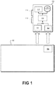
- Figure 1 depicts a simplified schematic view of a data collection unit 100 for taking measurements of operating conditions of a machine 102, according to an embodiment.
- the machine 102 may be any type of device or devices, for example, industrial machinery such as engines, motors, compressors, turbines, etc.
- the unit 100 may include a probe 104, which may be or include any suitable type of sensor or multiple sensors of the same or different types.
- the probe 104 may be or include a temperature sensor such as a thermistor, thermocouple, infrared sensor, or the like, a velocity sensor, an accelerometer, a vibration sensor, a potentiometer, an ammeter, an ohmmeter, a magnetic field sensor, and/or any other suitable type of sensor configured to collect any type of data characterizing operation of the machine 102.
- the probe 104 may be configured to measure multiple types of operating conditions (e.g., temperature and vibration) simultaneously, sequentially, selectively, or a combination thereof.
- the unit 100 may also include a tag reader 106.
- the tag reader 106 may be configured to receive information from a location tag 108.
- the location tag 108 may be located physically proximal to the machine 102 and thus may be characterized as being "associated with" or "of' the machine 102.
- the location tag 108 may be mounted to a nearby wall or floor, fixed to a portion of the machine 102, or otherwise secured proximal to the machine 102.
- the location tag 108 being "proximal to" the machine 102 may include the location tag 108 being positioned inside the machine 102.
- the location tag 108 may be a radio-frequency identification (RFID) tag. Accordingly, the location tag 108 and the tag reader 106 may form an RFID system of any type, such as a passive reader active tag system, active reader passive tag system, an active reader active tag system, or any other type of system.
- the tag reader 106 may include an inductor coil or another type of exciter that is configured to supply energy to the location tag 108. Such energy supply may cause the location tag 108 to transmit information back to the tag reader 106.
- the location tag 108 and tag reader 108 may be configured to communicate across any suitable distance.
- the location tag 108 may be a near-field communication (NFC) tag, requiring the tag reader 106 be immediately proximal to the location tag 108, or may be any other type of RFID tag configured for communication at any suitable range from the location tag 108, e.g., within a footprint of the machine 102.
- NFC near-field communication
- the information read from the location tag 108 may include a tag identifier, which may be unique.
- the tag identifier may be associated with other information, such as, for example, a serial number, location, model, and/or type, of the machine 102 to which it is affixed.
- the tag identifier may be or include direct identifying information of the machine, such as its model and/or serial number.
- the location tag 108 may include additional information, such as expected operating conditions and/or an operating envelope of the machine 102, which may be read and employed by the unit 100 in making determinations, as will be described in greater detail below.
- the unit 100 may also include one or more processors 110, a display 112, and a database 114.
- the processor 110 may be any suitable type of processor and may be configured to communicate with the probe 104 and the tag reader 106, so as to at least receive information therefrom.
- the processor 110 may also be coupled with the display 112. Accordingly, the processor 110 may receive and interpret data collected using the probe 104 and/or the tag reader 106, and show the data on the display 112 so the user may read the data.
- the display 112 may be any suitable type of display, such as a liquid crystal display (LCD), touchscreen, or any other suitable type of display.
- LCD liquid crystal display
- the database 114 may be contained on any suitable computer-readable medium or media.
- the computer-readable medium may be disposed on-board the unit 100 and/or removable; for example, the medium may be a flash drive. In other embodiments, the on-board computer-readable medium may require disassembly of the unit 100 to be removed, and thus may be considered permanently integrated with the unit 100.
- the computer-readable medium may be external and linked to the processor 110 via a wired (e.g., universal serial bus (USB), Ethernet, or the like) or a wireless (e.g., Bluetooth) connection, while still being considered as included in the unit 100.
- the database 114 may store data collected by the probe 104 and information (e.g., the tag identifiers) read by the tag reader 106.
- the unit 100 may be integrated, such that the probe 104, tag reader 106, processor 110, display 112, and/or database 114 may be disposed in a casing, in a generally permanent manner.
- the casing may be ruggedized so as to protect the components of the unit 100 from mechanical impacts, water, chemicals, electrical shock, etc.
- one or more components of the unit 100 may be removable and/or replaceable, according to a modular embodiment of the unit 100.
- the probe 104 and/or tag reader 106 may be integrated in the unit 100, or may be removably secured, e.g., to the casing of the unit 100, and coupled to the processor 110 via a data link (e.g., a universal serial bus (USB) connection), and removable therefrom.
- the unit 100 may be a special-purpose device, configured and/or optimized to be used generally exclusively for data collection from the machine 102.
- the unit 100 may be a general-purpose mobile device, which may be extensible by including one or more various type of probes 104 and/or tag readers 106, e.g., as peripheral input device. In either example, the unit 100 may be considered as "including" the probe 104 and tag reader 106.
- mobile device may refer to any type of mobile or standalone device, including any combination of hardware and software, capable of supporting the functionalities and data processing/transmitting techniques discussed herein.
- the unit 100 may be or include a mobile phone, a tablet device, a notebook device, a personal data assistant (PDA), or the like.
- PDA personal data assistant
- the unit 100 may also include one or more input indicators, such as buttons 116, 118.
- the buttons 116, 118 may be physical, raised buttons that are depressible by a user, or may be areas of a touchscreen.
- the input indicator may be a microphone and/or camera configured to receive audio and/or visual input, respectively.
- the button 116 may be employed to activate the unit 100.
- the button 116 may be configured to power up the unit.
- the button 116 may indicate to the processor 110 that a data collection session is to begin, e.g., by the processor 110 instructing the probe 104 to begin collecting data.
- the button 118 may be employed to indicate a hold mode. As such, when the button 118 is depressed, the unit 100 may continue to display the most recent data point collected, for example, until the button 118 is released, pressed again, or the hold mode is otherwise deactivated.
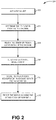
- FIG. 2 illustrates a flowchart of a method 200 for collecting data, according to an embodiment.
- Embodiments of the method 200 may proceed by operation of the unit 100 discussed above, and thus, for convenience, the method 200 is described herein with reference thereto. However, it will be understood that the method 200 is not limited to any particular hardware or structure, unless otherwise expressly stated herein.
- the method 200 may begin by activating the unit 100, as at 202. Activating the unit 100 at 202 may include a user pressing the button 116, instructing the unit 100 to execute a data collection application, or otherwise indicating to the unit 100 that the user is prepared to employ the unit 100 to collect data from the machine 102. Such activation may cause the processor 110 of the unit 100 to activate the probe 104.
- the method 200 may then proceed to the unit 100 determining that it is physically proximal to the machine 102, as at 204.
- the term "physically proximal" (or any grammatical variant thereof), as it is used herein, may be a distance from the machine 102 within which the probe 104 is able to accurately measure a selected operating condition of the machine 102.
- the probe 104 may be required to be within a certain distance from a portion of the machine 102 to accurately measure data for the operation of the machine 102. If the probe 104 is too far away, the measurements may be affected by the ambient conditions (e.g., temperature, magnetic field, etc.).
- the probe 104 may be required to be in contact with the machine 102, such as, for example, to detect vibration, electrical operating conditions, etc. Accordingly, whether the unit 100 is "physically proximal," as the term is used herein, may be affected by what type of data is to be collected.
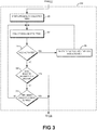
- Figure 3 illustrates a flowchart of a process for determining at 204 that the unit 100 is physically proximal to the machine 102, according to an embodiment.
- the determining process 204 may begin by starting a preliminary data collection timer, as at 300.
- the preliminary data collection timer may be set to any suitable value, which may be on the order of milliseconds, seconds, minutes, or more.
- the preliminary data collection timer may be set to avoid delays of indeterminate length while the unit 100 determines that it is disposed physically proximal to the machine 102.
- the unit 100 may then proceed to collecting preliminary data using the probe 104, as at 302. Such collection may proceed by taking one or more preliminary measurements, for example, a first preliminary measurement and a second preliminary measurement. During, subsequent to, or before such preliminary data collection at 302, the unit 100 may also determine whether a hold is activated, as at 304.
- the hold may be activated via one or more of the input indicators, for example, the button 118. Accordingly, a hold activation may be a process interrupt, which may occur at any point in the method 200. In other cases, detecting the hold at 304 may be an event that occurs in sequence at any predetermined point(s) in the method 200.
- the unit 100 may freeze the display 112, as at 306, for example, showing the most recent data collected at 302. In some cases, however, no data may have been collected at 302, and the display 112 may be frozen with the last data point collected in a previous data collection session.
- the display may be frozen at 306 until the hold is de-activated.
- the button 118 may be pressed again, released, or another button or other type of input indicator may cause the unit 100 to end the hold at 306. Thereafter, the unit 100 may return to the point in the determining process 204 at which the hold was detected. In other cases, the unit 100 may proceed directly back to collecting data at 302 and/or may reset the preliminary data collection timer at 300. Initiating the hold may or may not toll the preliminary data collection timer. In yet other embodiments, freezing the display at 306 may not stop the data collection at 302, and thus the determining process 204 may continue during the hold.
- the unit 100 undertaking the determining process 204 may proceed to determining whether the preliminary data collected indicates the unit 100 is physically proximal to the machine 102, as at 308. If, for example, a difference between the first preliminary measurement and the second preliminary measurement indicates a rise in temperature, vibration, another type of data, or a combination thereof, above a threshold amount, percentage, and/or rate, the difference may indicate that the unit 100 is physically proximal to the machine 102. In other embodiments, any other data measurement variation, whether an increase or decrease, may indicate that the unit 100 is physically proximal to the machine 102.
- the unit 100 may compare a single measurement collected at 302 to an expected operating condition or a threshold above which physical proximity to the machine 102 may be assumed.
- an expected operating condition may be entered manually, read from the location tag 108, or otherwise preprogrammed into the unit 100.
- the determining process 204 may be complete. On the other hand, if the preliminary data does not indicate that the unit 100 is physically proximal to the machine 102, the determining process 204 may proceed to the unit 100 checking if the preliminary data collection timer has expired, as at 310. As noted above, the preliminary data collection timer may provide a set stopping point for the preliminary data collection at 302 and/or the determining process 204, in some cases, even if the preliminary data does not indicate that the unit 100 is positioned physically proximal to the machine 102. Accordingly, if the unit 100 determines that the preliminary data collection timer has not expired, determining at 204 may proceed back to collecting preliminary data using the probe 104, as at 302. Otherwise, the determining process 204 may be complete.
- the method 200 may proceed to reading a tag identifier from the location tag 108 associated with the machine 102, as at 206.
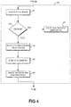
- Figure 4 illustrates a flowchart of a process for reading the location tag 108, at 206, according to an embodiment.
- the unit 100 may activate the tag reader 106, as at 402.
- Activating the tag reader 106 at 402 may include, for example, energizing one or more inductor coils of the tag reader 106, for example, in an embodiment in which the location tag 108 is one or more RFID tags. Such energizing may cause the location tag 108 to respond with a signal containing information such as the tag identifier.
- the unit 100 may determine whether the location tag 108 is found, as at 404, based on whether the tag reader 106 receives a responsive signal from the location tag 108 after energizing the tag reader 106. On the other hand, if an amount of time expires during which no responsive signal is received, the unit 100 may determine that it is unable to find a location tag 108. In such case, the display 112 may display an error message and/or request that the unit 100 be moved closer to the location tag 108 and/or the method 200 may proceed to collecting data for display and/or storage without association with a location tag 108, as at 405.
- the unit 100 may preserve basic functionality of condition monitoring of the machine 102 and may, for example, determine whether operating conditions are indicative of component failure, off-design operating conditions, dangerous conditions, and/or the like. Further, the data collection at 405 may also include detecting a steady-state measurement, freezing the display, etc., as will be described in greater detail below.
- the reading process 206 may proceed to receiving the tag identifier from the location tag 108, as at 406. Further, in response to a successful reception of the tag identifier, the processor 110 may, for example, cause the database 114 to store the tag identifier, as at 407.
- the unit 100 may also indicate that the location tag 108 was successfully found and/or read, as at 408. Such an indication may be visual, for example, by indication on the display 112.
- the indication may be effected by an indicator light (e.g., a light-emitting diode (LED) lighting, flashing, etc.), or it may be audible (e.g., via a tone from a speaker), or the unit 100 may shake or vibrate.
- an indicator light e.g., a light-emitting diode (LED) lighting, flashing, etc.
- audible e.g., via a tone from a speaker
- the unit 100 may shake or vibrate.
- the user may be made aware of whether the unit 100 has found the location tag 108 and is proceeding through to subsequent portions of the method 200, or whether the location tag 108 was not found at 404, and the unit 100 is proceeding with basic functionality.
- the method 200 may proceed to detecting a steady-state measurement, as at 208. In some embodiments, however, detecting at 208 may precede reading the location tag 108 at 206 or may be simultaneous therewith.
- Figure 5 illustrates a flowchart of a process for detecting a steady-state measurement at 208, according to an embodiment. As shown, the detection process 208 may begin by indicating that data collection is underway, as at 500. Such an indication may be effected in any suitable way, for example, by showing a message on the display 112, causing an LED to light up, flash, change color, etc., by sounding a tone, and/or the like.
- the detection process 208 may, in some embodiments, include initiating a data acquisition timer, as at 501.
- the data acquisition timer may be set according to an estimated time before which steady-state measurement should be reached. Accordingly, the data acquisition timer may avoid the unit 100 becoming stalled, in case the unit 100 does not determine that steady-state is reached, for example, if the machine 102 is operating erratically or otherwise over a range of operating conditions.
- the data acquisition timer may be on the order of seconds, but in other cases may be milliseconds, minutes, etc.
- the detection process 208 may also include taking measurements using the probe 104, as at 502.
- the measurements taken at 502 may be sampled by the processor 110 at any suitable frequency.
- transient data not associated with the operating conditions of the machine 102 may be included in such measurements initially.
- the processor 110 may perform a settling analysis, as at 504, to determine when transients are attenuated and the probe 104 is reading substantially steady-state measurement, i.e., within a threshold of variation tolerance.
- a variety of such settling algorithms for such an analysis are known and any suitable settling algorithm may be employed.
- the unit 100 may proceed to determining if the data acquisition timer has expired, as at 508. If the data acquisition timer has expired, the unit 100 may assume the most recent data point collected, an average of the most recent data points, or the like is an estimation of the steady-state measurement. If an estimation of the steady-state measurement is used, a warning message or other indicator of such estimation may be displayed or otherwise signaled to the user. On the other hand, if the data acquisition timer has not expired, the unit 100 may return to collecting data at 502, since the transients still appear to be present and the data acquisition timer has not forced an end to data collection. This loop may continue until either the settling constraints are satisfied at 506 or the data acquisition timer expires at 508.
- the processor 110 sampling the data measured by the probe 104 may determine if dangerous conditions exist. If such dangerous conditions are apparent, the processor 110 may indicate an alarm and/or take other remedial and or safety actions.
- the method 200 may continue to storing the steady-state measurement in association with the tag identifier, as at 210.
- the steady-state measurement may also be stored in association with a time and/or date (referred to in Figure 2 as a "timestamp") at which the measurement was taken.
- the processor 110 may cause the measurement (and/or timestamp) to be stored in the database 114, for example, in a database object associating the measurement, the tag identifier, and the timestamp.
- multiple data collections of multiple different machines 102 may be stored in the same database 114, for example, for downloading to a computing device for subsequent analysis (e.g. trending, diagnosis, etc.).
- the unit 100 may collect multiple measurements over time and may store such measurements in the database 114, e.g., in association with the tag identifier and/or any other information. This may allow frequency responses and/or other system reactions to perturbations and/or operating point changes, or any other operating conditions to be observed over time and stored for later analysis.
- the measurement stored at 210 may include the measurements taken at 502 and/or, in some cases, may also include one or more preliminary measurements taken at 302.
- the method 200 may also include ending data collection, e.g., by powering down the probe 104 and/or the processor 110 ceasing to sample data from the probe 104.
- the unit 100 may enter another hold mode, freezing the display 112, as at 212, such that the display 112 shows the most recent (e.g., the steady-state) measurement. This may allow for the unit 100 to be removed from contact with the machine 102, e.g., after the termination of data collection, and the display 112 read by an operator.
- Such freezing of the display 112 may be considered storing of the measurement at 210, since it is available for subsequent retrieval and/or analysis, or it may be considered separately, as shown.
- the display 112 may remain frozen until an input indicator releases the display 112 from this second hold mode, such as, for example, by pressing the button 118, by powering down the unit 100, or in any other suitable way.
- FIG. 6 illustrates a schematic view of a computing or processor system 600, according to an embodiment.
- the processor system 600 may be embodied by hardware and/or software included in the unit 100, and thus may operate to implement one or more aspects of the method 200. Further, it will be appreciated that in various embodiments, the unit 100 may include multiple processor systems 600.
- the processor system 600 may include one or more processors 602 of varying core configurations (including multiple cores) and clock frequencies.
- the one or more processors 602 may be operable to execute instructions, apply logic, etc. It may be appreciated that these functions may be provided by multiple processors or multiple cores on a single chip operating in parallel and/or communicably linked together.
- the processor system 600 may also include a memory system, which may be or include one or more memory devices and/or computer-readable media 604 of varying physical dimensions, accessibility, storage capacities, etc. such as flash drives, hard drives, disks, random access memory, etc., for storing data, such as images, files, and program instructions for execution by the processor 602.
- the computer-readable media 604 may store instructions that, when executed by the processor 602, are configured to cause the processor system 600 to perform operations. For example, execution of such instructions may cause the processor system 600 to implement one or more portions and/or embodiments of the method 200 described above.
- the processor system 600 may also include one or more network interfaces 606.
- the network interfaces 606 may include any hardware, applications, and/or other software. Accordingly, the network interfaces 606 may include Ethernet adapters, wireless transceivers, PCI interfaces, and/or serial network components, for communicating over wired or wireless media using protocols, such as Ethernet, wireless Ethernet, etc.
- the processor system 600 may further include one or more peripheral interfaces 608, for communication with the display 112, the input indictors, and, in some cases, the probe 104 and/or the tag reader 106.
- the peripheral interface 608 may also communicate with any projectors, keyboards, mice, touchpads, sensors, other types of input and/or output peripherals, and/or the like connected to the unit 100.
- the components of processor system 600 need not be enclosed within a single enclosure or even located in close proximity to one another, but in other implementations, the components and/or others may be provided in a single enclosure.
- the memory device 604 may be physically or logically arranged or configured to store data on one or more storage devices 610.
- the storage device 610 may include one or more file systems or databases, such as the database 114 in any suitable format.
- the storage device 610 may also include one or more software programs 612, which may contain interpretable or executable instructions for performing one or more of the disclosed processes. When requested by the processor 602, one or more of the software programs 612, or a portion thereof, may be loaded from the storage devices 610 to the memory devices 604 for execution by the processor 602.
- processor system 600 may include any type of hardware components, including any necessary accompanying firmware or software, for performing the disclosed implementations.
- the processor system 600 may also be implemented in part or in whole by electronic circuit components or processors, such as application-specific integrated circuits (ASICs) or field-programmable gate arrays (FPGAs).
- ASICs application-specific integrated circuits
- FPGAs field-programmable gate arrays
- processor system 600 may be used to execute programs according to instructions received from another program or from another processor system altogether.
- commands may be received, executed, and their output returned entirely within the processing and/or memory of the processor system 600. Accordingly, neither a visual interface command terminal nor any terminal at all is strictly necessary for performing the described embodiments.
- first and second features are formed in direct contact
- additional features may be formed interposing the first and second features, such that the first and second features may not be in direct contact.
Landscapes
- Engineering & Computer Science (AREA)
- Physics & Mathematics (AREA)
- Health & Medical Sciences (AREA)
- Toxicology (AREA)
- General Physics & Mathematics (AREA)
- Computer Networks & Wireless Communication (AREA)
- Theoretical Computer Science (AREA)
- Electromagnetism (AREA)
- General Health & Medical Sciences (AREA)
- Artificial Intelligence (AREA)
- Computer Vision & Pattern Recognition (AREA)
- Computer Hardware Design (AREA)
- Microelectronics & Electronic Packaging (AREA)
- Arrangements For Transmission Of Measured Signals (AREA)
- Measurement Of The Respiration, Hearing Ability, Form, And Blood Characteristics Of Living Organisms (AREA)
Claims (10)
- Verfahren zum Sammeln von Daten, das Folgendes umfasst:Empfangen einer Etikett-Kennung von einem Etikett (108), das in, auf oder in der Nähe einer Maschine (102) positioniert ist, unter Verwendung eines Etikett-Lesegeräts (106) einer Datensammeleinheit (100);Durchführen mehrerer Messungen von einer oder mehreren Betriebsbedingungen der Maschine unter Verwendung eines Sensors (104) der Datensammeleinheit;Finden einer stationären Messung unter Verwendung der Datensammeleinheit durch Durchführen einer Einstellanalyse, um zu bestimmen, wann sich die mehreren Messungen innerhalb eines Schwellenwerts eingestellt haben;Speichern der stationären Messung; undVerbinden der stationären Messung mit der Etikett-Kennung.
- Verfahren nach Anspruch 1, das ferner das Bestimmen unter Verwendung der Datensammeleinheit umfasst, dass sich die Datensammeleinheit (100) physikalisch proximal zu der Maschine (102) befindet.
- Verfahren nach Anspruch 2, wobei das Bestimmen, dass die Datensammeleinheit sich physikalisch proximal zu der Maschine befindet, Folgendes umfasst:Durchführen einer ersten vorläufigen Messung unter Verwendung des Sensors (104);Durchführen einer zweiten vorläufigen Messung unter Verwendung des Sensors; undBestimmen, dass eine Differenz zwischen der ersten vorläufigen Messung und der zweiten vorläufigen Messung anzeigt, dass der Sensor Daten misst, die mit dem Betrieb der Maschine (102) verbunden sind.
- Verfahren nach Anspruch 2, wobei das Bestimmen, dass sich die Datensammeleinheit physikalisch proximal zu der Maschine befindet, Folgendes umfasst:Durchführen einer vorläufigen Messung unter Verwendung des Sensors; undBestimmen, dass die vorläufige Messung anzeigt, dass der Sensor Daten misst, die mit dem Betrieb der Maschine (102) verbunden sind.
- Verfahren nach Anspruch 2, wobei das Bestimmen, dass die Datensammeleinheit sich physikalisch proximal zu der Maschine befindet, Folgendes umfasst:Initiieren eines vorläufigen Datensammelzeitgebers;Durchführen einer oder mehrerer vorläufiger Messungen unter Verwendung des Sensors; undBestimmen, dass der Datensammelzeitgeber abgelaufen ist, bevor eine oder mehrere vorläufige Messungen anzeigen, dass die Datensammeleinheit physikalisch proximal zu der Maschine ist.
- Verfahren nach Anspruch 1, wobei das Etikett einem Funkfrequenz-Identifikations-Etikett entspricht.
- Verfahren nach Anspruch 1, wobei das Finden der stationären Messung ferner Folgendes umfasst:Initiieren eines Datensammelzeitgebers;Bestimmen, dass der Datensammelzeitgeber abgelaufen ist, bevor die Einstellanalyse anzeigt, dass sich die mehreren Messungen eingestellt haben; undSchätzen der stationären Messung basierend auf einer oder mehrerer der mehreren Messungen.
- Verfahren nach Anspruch 1, wobei das Speichern der Messung das Anhalten einer Anzeige (112) der Datensammeleinheit umfasst, wobei die Anzeige die Messung zeigt.
- Nichtflüchtiges computerlesbares Medium, das Anweisungen enthält, die dann, wenn sie ausgeführt werden, konfiguriert sind, eine Datensammeleinheit (100), die ein Etikett-Lesegerät (106) und einen Sensor (104) umfasst, zu veranlassen, das Verfahren zum Sammeln von Daten nach einem der vorhergehenden Ansprüche durchzuführen.
- Datensammeleinheit (100), die Folgendes umfasst:einen oder mehrere Sensoren (104) zum Durchführen von Messungen der Betriebsbedingungen einer Maschine (102);ein Etikett-Lesegerät (106), das konfiguriert ist, Informationen von einem Etikett (108), das sich physikalisch proximal zu der Maschine befindet, zu empfangen;einen oder mehrere Prozessoren (110, 602), die konfiguriert sind, mit dem einen oder den mehreren Sensoren (104) und dem Etikett-Lesegerät (106) zu kommunizieren; undein Speichersystem (604), das Programmanweisungen enthält, die dann, wenn sie ausgeführt werden, den einen oder die mehreren Prozessoren veranlassen, das Verfahren zum Sammeln von Daten nach einem der Ansprüche 1 bis 7 durchzuführen.
Applications Claiming Priority (2)
| Application Number | Priority Date | Filing Date | Title |
|---|---|---|---|
| US13/872,406 US9171192B2 (en) | 2013-04-29 | 2013-04-29 | One touch data collection method and medium |
| PCT/US2014/035869 WO2014179312A1 (en) | 2013-04-29 | 2014-04-29 | One touch data collection method and medium |
Publications (3)
| Publication Number | Publication Date |
|---|---|
| EP2992518A1 EP2992518A1 (de) | 2016-03-09 |
| EP2992518A4 EP2992518A4 (de) | 2017-01-18 |
| EP2992518B1 true EP2992518B1 (de) | 2019-10-23 |
Family
ID=51788778
Family Applications (1)
| Application Number | Title | Priority Date | Filing Date |
|---|---|---|---|
| EP14791030.1A Active EP2992518B1 (de) | 2013-04-29 | 2014-04-29 | One-touch-datenerfassungsverfahren und medium |
Country Status (5)
| Country | Link |
|---|---|
| US (1) | US9171192B2 (de) |
| EP (1) | EP2992518B1 (de) |
| CN (1) | CN105264584B (de) |
| BR (1) | BR112015027311A2 (de) |
| WO (1) | WO2014179312A1 (de) |
Families Citing this family (3)
| Publication number | Priority date | Publication date | Assignee | Title |
|---|---|---|---|---|
| WO2016085623A1 (en) * | 2014-11-26 | 2016-06-02 | Aktiebolaget Skf | Sensory head with storage and power |
| CN106231541A (zh) * | 2016-08-10 | 2016-12-14 | 苏州邦拓机电科技有限公司 | 五金机电工具与智能终端的数据传输及处理系统 |
| FR3103893B1 (fr) * | 2019-11-29 | 2021-11-12 | Safran Aircraft Engines | Système et procédé d’identification de paramètres d’un capteur fixé sur un carter |
Citations (1)
| Publication number | Priority date | Publication date | Assignee | Title |
|---|---|---|---|---|
| WO2014093963A1 (en) * | 2012-12-14 | 2014-06-19 | Aktiebolaget Skf | Portable data collection system and method |
Family Cites Families (15)
| Publication number | Priority date | Publication date | Assignee | Title |
|---|---|---|---|---|
| US5633811A (en) * | 1994-12-09 | 1997-05-27 | Computational Systems, Inc. | Hand held data collector and analyzer system |
| US6078874A (en) * | 1998-08-04 | 2000-06-20 | Csi Technology, Inc. | Apparatus and method for machine data collection |
| SE526204C2 (sv) * | 2004-11-24 | 2005-07-26 | Electrotech Ab | Mätanordning för tillståndskontroll vid rondering |
| US7275682B2 (en) * | 2005-03-24 | 2007-10-02 | Varian, Inc. | Sample identification utilizing RFID tags |
| EP1898776B1 (de) * | 2005-05-24 | 2012-08-15 | Koninklijke Philips Electronics N.V. | Automatische identifikation von punktmessungen |
| US20070200722A1 (en) * | 2006-02-27 | 2007-08-30 | Csi Technology, Inc. | Belt pack accessory for machine condition monitoring |
| US20070199989A1 (en) * | 2006-02-27 | 2007-08-30 | Csi Technology, Inc. | Combined machine identification and diagnosis device |
| US20080201388A1 (en) * | 2007-02-20 | 2008-08-21 | Luke Wood | System and method for equipment tracking and preventative maintenance scheduling and verification |
| US20080309507A1 (en) * | 2007-06-12 | 2008-12-18 | Paul Gene Anderson | Self-configuring data acquisition system for diagnostic testing |
| US7843192B2 (en) * | 2007-08-16 | 2010-11-30 | National Research Council Of Canada | Kit, method and apparatus for monitoring operation of a bearing assembly, method for producing said apparatus, and bearing assembly with a condition monitor |
| US7756678B2 (en) * | 2008-05-29 | 2010-07-13 | General Electric Company | System and method for advanced condition monitoring of an asset system |
| US9226686B2 (en) * | 2009-11-23 | 2016-01-05 | Rf Surgical Systems, Inc. | Method and apparatus to account for transponder tagged objects used during medical procedures |
| US7793850B1 (en) * | 2010-03-14 | 2010-09-14 | Kd Secure Llc | System and method used for configuration of an inspection compliance tool with machine readable tags and their associations to inspected components |
| US20130057390A1 (en) * | 2010-05-26 | 2013-03-07 | Sri International | Radio frequency identification tags for use in extreme environments |
| EP2877659A4 (de) * | 2012-07-25 | 2016-04-13 | Master Lock Co | Integrierte antennenspule in einem metallischen körper |
-
2013
- 2013-04-29 US US13/872,406 patent/US9171192B2/en active Active
-
2014
- 2014-04-29 WO PCT/US2014/035869 patent/WO2014179312A1/en not_active Ceased
- 2014-04-29 EP EP14791030.1A patent/EP2992518B1/de active Active
- 2014-04-29 CN CN201480028861.9A patent/CN105264584B/zh not_active Expired - Fee Related
- 2014-04-29 BR BR112015027311A patent/BR112015027311A2/pt not_active IP Right Cessation
Patent Citations (1)
| Publication number | Priority date | Publication date | Assignee | Title |
|---|---|---|---|---|
| WO2014093963A1 (en) * | 2012-12-14 | 2014-06-19 | Aktiebolaget Skf | Portable data collection system and method |
Also Published As
| Publication number | Publication date |
|---|---|
| CN105264584B (zh) | 2018-05-18 |
| EP2992518A1 (de) | 2016-03-09 |
| US9171192B2 (en) | 2015-10-27 |
| BR112015027311A2 (pt) | 2017-07-25 |
| WO2014179312A1 (en) | 2014-11-06 |
| US20140320303A1 (en) | 2014-10-30 |
| EP2992518A4 (de) | 2017-01-18 |
| CN105264584A (zh) | 2016-01-20 |
Similar Documents
| Publication | Publication Date | Title |
|---|---|---|
| US9773135B2 (en) | Portable data collection system and method | |
| US10983097B2 (en) | Automatic mechanical systems diagnosis | |
| KR101213252B1 (ko) | 가축 온도 감지 장치 및 이를 이용한 원격으로 이루어지는 가축의 질병 진단 시스템 및 이의 방법 | |
| WO2014145153A2 (en) | Automatic recording and graphing of measurement data | |
| EP3338171B1 (de) | Immer eingeschaltete sensorvorrichtung für menschliche berührung | |
| CN110542484A (zh) | 用于温度检测的巡检装置、巡检系统及方法 | |
| US9171192B2 (en) | One touch data collection method and medium | |
| US8973815B2 (en) | One touch data collection apparatus | |
| US20070200722A1 (en) | Belt pack accessory for machine condition monitoring | |
| US20150177208A1 (en) | Gas sensor with interface to hand-held instrument | |
| CN113795735B (zh) | 用于监测旋转装置的方法以及状态监测设备 | |
| JP2008522785A5 (de) | ||
| KR101033964B1 (ko) | 무선 혈압 및 맥파 측정장치 | |
| US20150177193A1 (en) | Ultrasonic thickness gauge with interface to hand-held instrument | |
| EP2747301A1 (de) | Kommunikationsprogramm, Informationsverarbeitungsvorrichtung, Kommunikationssystem und Kommunikationsverfahren | |
| RU2700905C2 (ru) | Адаптивный и управляемый состояниями сбор данных | |
| US20150178531A1 (en) | Sensory head with storage and power | |
| WO2016085623A1 (en) | Sensory head with storage and power | |
| WO2016085625A1 (en) | Sensory head with multiple sensors | |
| KR102424463B1 (ko) | 채혈확인장치 및 그 장치의 구동방법 | |
| US20060217599A1 (en) | Biological information collecting system | |
| US20060232400A1 (en) | Biological information collecting system | |
| CN110505132B (zh) | 一种肺功能数据传输的软件实现方法 | |
| US20150177266A1 (en) | Sensory head with multiple sensors | |
| KR20210042688A (ko) | 3가지 측정 센서를 이용한 가축용 전염병 알림 시스템 |
Legal Events
| Date | Code | Title | Description |
|---|---|---|---|
| PUAI | Public reference made under article 153(3) epc to a published international application that has entered the european phase |
Free format text: ORIGINAL CODE: 0009012 |
|
| 17P | Request for examination filed |
Effective date: 20151110 |
|
| AK | Designated contracting states |
Kind code of ref document: A1 Designated state(s): AL AT BE BG CH CY CZ DE DK EE ES FI FR GB GR HR HU IE IS IT LI LT LU LV MC MK MT NL NO PL PT RO RS SE SI SK SM TR |
|
| AX | Request for extension of the european patent |
Extension state: BA ME |
|
| DAX | Request for extension of the european patent (deleted) | ||
| A4 | Supplementary search report drawn up and despatched |
Effective date: 20161215 |
|
| RIC1 | Information provided on ipc code assigned before grant |
Ipc: G06K 19/07 20060101ALI20161209BHEP Ipc: G08B 13/14 20060101AFI20161209BHEP Ipc: H04Q 9/00 20060101ALI20161209BHEP Ipc: G06K 7/10 20060101ALI20161209BHEP |
|
| STAA | Information on the status of an ep patent application or granted ep patent |
Free format text: STATUS: EXAMINATION IS IN PROGRESS |
|
| 17Q | First examination report despatched |
Effective date: 20181018 |
|
| GRAP | Despatch of communication of intention to grant a patent |
Free format text: ORIGINAL CODE: EPIDOSNIGR1 |
|
| STAA | Information on the status of an ep patent application or granted ep patent |
Free format text: STATUS: GRANT OF PATENT IS INTENDED |
|
| INTG | Intention to grant announced |
Effective date: 20190521 |
|
| RIN1 | Information on inventor provided before grant (corrected) |
Inventor name: MURPHY, JONATHAN DAVID |
|
| GRAS | Grant fee paid |
Free format text: ORIGINAL CODE: EPIDOSNIGR3 |
|
| GRAA | (expected) grant |
Free format text: ORIGINAL CODE: 0009210 |
|
| STAA | Information on the status of an ep patent application or granted ep patent |
Free format text: STATUS: THE PATENT HAS BEEN GRANTED |
|
| AK | Designated contracting states |
Kind code of ref document: B1 Designated state(s): AL AT BE BG CH CY CZ DE DK EE ES FI FR GB GR HR HU IE IS IT LI LT LU LV MC MK MT NL NO PL PT RO RS SE SI SK SM TR |
|
| REG | Reference to a national code |
Ref country code: GB Ref legal event code: FG4D |
|
| REG | Reference to a national code |
Ref country code: CH Ref legal event code: EP |
|
| REG | Reference to a national code |
Ref country code: IE Ref legal event code: FG4D |
|
| REG | Reference to a national code |
Ref country code: DE Ref legal event code: R096 Ref document number: 602014055643 Country of ref document: DE |
|
| REG | Reference to a national code |
Ref country code: AT Ref legal event code: REF Ref document number: 1194534 Country of ref document: AT Kind code of ref document: T Effective date: 20191115 |
|
| REG | Reference to a national code |
Ref country code: NL Ref legal event code: MP Effective date: 20191023 |
|
| REG | Reference to a national code |
Ref country code: LT Ref legal event code: MG4D |
|
| PG25 | Lapsed in a contracting state [announced via postgrant information from national office to epo] |
Ref country code: ES Free format text: LAPSE BECAUSE OF FAILURE TO SUBMIT A TRANSLATION OF THE DESCRIPTION OR TO PAY THE FEE WITHIN THE PRESCRIBED TIME-LIMIT Effective date: 20191023 Ref country code: LV Free format text: LAPSE BECAUSE OF FAILURE TO SUBMIT A TRANSLATION OF THE DESCRIPTION OR TO PAY THE FEE WITHIN THE PRESCRIBED TIME-LIMIT Effective date: 20191023 Ref country code: SE Free format text: LAPSE BECAUSE OF FAILURE TO SUBMIT A TRANSLATION OF THE DESCRIPTION OR TO PAY THE FEE WITHIN THE PRESCRIBED TIME-LIMIT Effective date: 20191023 Ref country code: PT Free format text: LAPSE BECAUSE OF FAILURE TO SUBMIT A TRANSLATION OF THE DESCRIPTION OR TO PAY THE FEE WITHIN THE PRESCRIBED TIME-LIMIT Effective date: 20200224 Ref country code: BG Free format text: LAPSE BECAUSE OF FAILURE TO SUBMIT A TRANSLATION OF THE DESCRIPTION OR TO PAY THE FEE WITHIN THE PRESCRIBED TIME-LIMIT Effective date: 20200123 Ref country code: NO Free format text: LAPSE BECAUSE OF FAILURE TO SUBMIT A TRANSLATION OF THE DESCRIPTION OR TO PAY THE FEE WITHIN THE PRESCRIBED TIME-LIMIT Effective date: 20200123 Ref country code: FI Free format text: LAPSE BECAUSE OF FAILURE TO SUBMIT A TRANSLATION OF THE DESCRIPTION OR TO PAY THE FEE WITHIN THE PRESCRIBED TIME-LIMIT Effective date: 20191023 Ref country code: NL Free format text: LAPSE BECAUSE OF FAILURE TO SUBMIT A TRANSLATION OF THE DESCRIPTION OR TO PAY THE FEE WITHIN THE PRESCRIBED TIME-LIMIT Effective date: 20191023 Ref country code: LT Free format text: LAPSE BECAUSE OF FAILURE TO SUBMIT A TRANSLATION OF THE DESCRIPTION OR TO PAY THE FEE WITHIN THE PRESCRIBED TIME-LIMIT Effective date: 20191023 Ref country code: PL Free format text: LAPSE BECAUSE OF FAILURE TO SUBMIT A TRANSLATION OF THE DESCRIPTION OR TO PAY THE FEE WITHIN THE PRESCRIBED TIME-LIMIT Effective date: 20191023 Ref country code: GR Free format text: LAPSE BECAUSE OF FAILURE TO SUBMIT A TRANSLATION OF THE DESCRIPTION OR TO PAY THE FEE WITHIN THE PRESCRIBED TIME-LIMIT Effective date: 20200124 |
|
| PG25 | Lapsed in a contracting state [announced via postgrant information from national office to epo] |
Ref country code: RS Free format text: LAPSE BECAUSE OF FAILURE TO SUBMIT A TRANSLATION OF THE DESCRIPTION OR TO PAY THE FEE WITHIN THE PRESCRIBED TIME-LIMIT Effective date: 20191023 Ref country code: IS Free format text: LAPSE BECAUSE OF FAILURE TO SUBMIT A TRANSLATION OF THE DESCRIPTION OR TO PAY THE FEE WITHIN THE PRESCRIBED TIME-LIMIT Effective date: 20200224 Ref country code: HR Free format text: LAPSE BECAUSE OF FAILURE TO SUBMIT A TRANSLATION OF THE DESCRIPTION OR TO PAY THE FEE WITHIN THE PRESCRIBED TIME-LIMIT Effective date: 20191023 |
|
| PG25 | Lapsed in a contracting state [announced via postgrant information from national office to epo] |
Ref country code: AL Free format text: LAPSE BECAUSE OF FAILURE TO SUBMIT A TRANSLATION OF THE DESCRIPTION OR TO PAY THE FEE WITHIN THE PRESCRIBED TIME-LIMIT Effective date: 20191023 |
|
| REG | Reference to a national code |
Ref country code: DE Ref legal event code: R097 Ref document number: 602014055643 Country of ref document: DE |
|
| PG2D | Information on lapse in contracting state deleted |
Ref country code: IS |
|
| PG25 | Lapsed in a contracting state [announced via postgrant information from national office to epo] |
Ref country code: RO Free format text: LAPSE BECAUSE OF FAILURE TO SUBMIT A TRANSLATION OF THE DESCRIPTION OR TO PAY THE FEE WITHIN THE PRESCRIBED TIME-LIMIT Effective date: 20191023 Ref country code: EE Free format text: LAPSE BECAUSE OF FAILURE TO SUBMIT A TRANSLATION OF THE DESCRIPTION OR TO PAY THE FEE WITHIN THE PRESCRIBED TIME-LIMIT Effective date: 20191023 Ref country code: CZ Free format text: LAPSE BECAUSE OF FAILURE TO SUBMIT A TRANSLATION OF THE DESCRIPTION OR TO PAY THE FEE WITHIN THE PRESCRIBED TIME-LIMIT Effective date: 20191023 Ref country code: DK Free format text: LAPSE BECAUSE OF FAILURE TO SUBMIT A TRANSLATION OF THE DESCRIPTION OR TO PAY THE FEE WITHIN THE PRESCRIBED TIME-LIMIT Effective date: 20191023 Ref country code: IS Free format text: LAPSE BECAUSE OF FAILURE TO SUBMIT A TRANSLATION OF THE DESCRIPTION OR TO PAY THE FEE WITHIN THE PRESCRIBED TIME-LIMIT Effective date: 20200223 |
|
| REG | Reference to a national code |
Ref country code: AT Ref legal event code: MK05 Ref document number: 1194534 Country of ref document: AT Kind code of ref document: T Effective date: 20191023 |
|
| PLBE | No opposition filed within time limit |
Free format text: ORIGINAL CODE: 0009261 |
|
| STAA | Information on the status of an ep patent application or granted ep patent |
Free format text: STATUS: NO OPPOSITION FILED WITHIN TIME LIMIT |
|
| PG25 | Lapsed in a contracting state [announced via postgrant information from national office to epo] |
Ref country code: SM Free format text: LAPSE BECAUSE OF FAILURE TO SUBMIT A TRANSLATION OF THE DESCRIPTION OR TO PAY THE FEE WITHIN THE PRESCRIBED TIME-LIMIT Effective date: 20191023 Ref country code: SK Free format text: LAPSE BECAUSE OF FAILURE TO SUBMIT A TRANSLATION OF THE DESCRIPTION OR TO PAY THE FEE WITHIN THE PRESCRIBED TIME-LIMIT Effective date: 20191023 Ref country code: IT Free format text: LAPSE BECAUSE OF FAILURE TO SUBMIT A TRANSLATION OF THE DESCRIPTION OR TO PAY THE FEE WITHIN THE PRESCRIBED TIME-LIMIT Effective date: 20191023 |
|
| 26N | No opposition filed |
Effective date: 20200724 |
|
| PG25 | Lapsed in a contracting state [announced via postgrant information from national office to epo] |
Ref country code: SI Free format text: LAPSE BECAUSE OF FAILURE TO SUBMIT A TRANSLATION OF THE DESCRIPTION OR TO PAY THE FEE WITHIN THE PRESCRIBED TIME-LIMIT Effective date: 20191023 Ref country code: AT Free format text: LAPSE BECAUSE OF FAILURE TO SUBMIT A TRANSLATION OF THE DESCRIPTION OR TO PAY THE FEE WITHIN THE PRESCRIBED TIME-LIMIT Effective date: 20191023 Ref country code: MC Free format text: LAPSE BECAUSE OF FAILURE TO SUBMIT A TRANSLATION OF THE DESCRIPTION OR TO PAY THE FEE WITHIN THE PRESCRIBED TIME-LIMIT Effective date: 20191023 |
|
| REG | Reference to a national code |
Ref country code: CH Ref legal event code: PL |
|
| PG25 | Lapsed in a contracting state [announced via postgrant information from national office to epo] |
Ref country code: CH Free format text: LAPSE BECAUSE OF NON-PAYMENT OF DUE FEES Effective date: 20200430 Ref country code: LI Free format text: LAPSE BECAUSE OF NON-PAYMENT OF DUE FEES Effective date: 20200430 Ref country code: FR Free format text: LAPSE BECAUSE OF NON-PAYMENT OF DUE FEES Effective date: 20200430 Ref country code: LU Free format text: LAPSE BECAUSE OF NON-PAYMENT OF DUE FEES Effective date: 20200429 |
|
| REG | Reference to a national code |
Ref country code: BE Ref legal event code: MM Effective date: 20200430 |
|
| PG25 | Lapsed in a contracting state [announced via postgrant information from national office to epo] |
Ref country code: BE Free format text: LAPSE BECAUSE OF NON-PAYMENT OF DUE FEES Effective date: 20200430 |
|
| GBPC | Gb: european patent ceased through non-payment of renewal fee |
Effective date: 20200429 |
|
| PG25 | Lapsed in a contracting state [announced via postgrant information from national office to epo] |
Ref country code: IE Free format text: LAPSE BECAUSE OF NON-PAYMENT OF DUE FEES Effective date: 20200429 Ref country code: GB Free format text: LAPSE BECAUSE OF NON-PAYMENT OF DUE FEES Effective date: 20200429 |
|
| PG25 | Lapsed in a contracting state [announced via postgrant information from national office to epo] |
Ref country code: TR Free format text: LAPSE BECAUSE OF FAILURE TO SUBMIT A TRANSLATION OF THE DESCRIPTION OR TO PAY THE FEE WITHIN THE PRESCRIBED TIME-LIMIT Effective date: 20191023 Ref country code: MT Free format text: LAPSE BECAUSE OF FAILURE TO SUBMIT A TRANSLATION OF THE DESCRIPTION OR TO PAY THE FEE WITHIN THE PRESCRIBED TIME-LIMIT Effective date: 20191023 Ref country code: CY Free format text: LAPSE BECAUSE OF FAILURE TO SUBMIT A TRANSLATION OF THE DESCRIPTION OR TO PAY THE FEE WITHIN THE PRESCRIBED TIME-LIMIT Effective date: 20191023 |
|
| PG25 | Lapsed in a contracting state [announced via postgrant information from national office to epo] |
Ref country code: MK Free format text: LAPSE BECAUSE OF FAILURE TO SUBMIT A TRANSLATION OF THE DESCRIPTION OR TO PAY THE FEE WITHIN THE PRESCRIBED TIME-LIMIT Effective date: 20191023 |
|
| P01 | Opt-out of the competence of the unified patent court (upc) registered |
Effective date: 20230513 |
|
| PGFP | Annual fee paid to national office [announced via postgrant information from national office to epo] |
Ref country code: DE Payment date: 20230427 Year of fee payment: 10 |
|
| REG | Reference to a national code |
Ref country code: DE Ref legal event code: R119 Ref document number: 602014055643 Country of ref document: DE |
|
| PG25 | Lapsed in a contracting state [announced via postgrant information from national office to epo] |
Ref country code: DE Free format text: LAPSE BECAUSE OF NON-PAYMENT OF DUE FEES Effective date: 20241105 |
|
| PG25 | Lapsed in a contracting state [announced via postgrant information from national office to epo] |
Ref country code: DE Free format text: LAPSE BECAUSE OF NON-PAYMENT OF DUE FEES Effective date: 20241105 |