EP2992359B1 - Vorrichtung und verfahren zur erfassung seismischer daten mit gleichzeitiger aktivierung von gebündelten vibratoren - Google Patents
Vorrichtung und verfahren zur erfassung seismischer daten mit gleichzeitiger aktivierung von gebündelten vibratoren Download PDFInfo
- Publication number
- EP2992359B1 EP2992359B1 EP14720156.0A EP14720156A EP2992359B1 EP 2992359 B1 EP2992359 B1 EP 2992359B1 EP 14720156 A EP14720156 A EP 14720156A EP 2992359 B1 EP2992359 B1 EP 2992359B1
- Authority
- EP
- European Patent Office
- Prior art keywords
- clusters
- seismic
- vibratory sources
- sources
- vibratory
- Prior art date
- Legal status (The legal status is an assumption and is not a legal conclusion. Google has not performed a legal analysis and makes no representation as to the accuracy of the status listed.)
- Active
Links
Images




Classifications
-
- G—PHYSICS
- G01—MEASURING; TESTING
- G01V—GEOPHYSICS; GRAVITATIONAL MEASUREMENTS; DETECTING MASSES OR OBJECTS; TAGS
- G01V1/00—Seismology; Seismic or acoustic prospecting or detecting
- G01V1/003—Seismic data acquisition in general, e.g. survey design
- G01V1/005—Seismic data acquisition in general, e.g. survey design with exploration systems emitting special signals, e.g. frequency swept signals, pulse sequences or slip sweep arrangements
-
- G—PHYSICS
- G01—MEASURING; TESTING
- G01V—GEOPHYSICS; GRAVITATIONAL MEASUREMENTS; DETECTING MASSES OR OBJECTS; TAGS
- G01V1/00—Seismology; Seismic or acoustic prospecting or detecting
- G01V1/02—Generating seismic energy
- G01V1/04—Details
- G01V1/09—Transporting arrangements, e.g. on vehicles
-
- G—PHYSICS
- G01—MEASURING; TESTING
- G01V—GEOPHYSICS; GRAVITATIONAL MEASUREMENTS; DETECTING MASSES OR OBJECTS; TAGS
- G01V2210/00—Details of seismic processing or analysis
- G01V2210/10—Aspects of acoustic signal generation or detection
- G01V2210/12—Signal generation
- G01V2210/127—Cooperating multiple sources
Definitions
- Embodiments of the subject matter disclosed herein generally relate to methods for seismic data acquisition using clustered seismic vibrators that are placed at different vibration points within a predetermined distance from one another and are activated simultaneously.
- Seismic surveys are commonly used to search for and evaluate subterranean hydrocarbon deposits. Seismic surveys are exploration methods that gather and record data related to seismic wave reflections from interfaces between geological layers. Seismic data is then used to create detailed models of the underlying geological structure.
- FIG. 1 schematically depicts a land seismic survey system 100 for seismic exploration in a land environment.
- System 100 includes a source 110 (e.g., a vibratory source) that generates seismic waves, receivers 120 (e.g., geophones) for detecting the seismic reflections, and a recorder 130.
- Recorder 130 is configured to record electrical signals or seismic data resulting from sampling electrical signals generated by receivers 120 upon detecting seismic reflections.
- source 110, receivers 120 and recorder 130 are positioned on ground surface 150.
- source 110 and recorder 130 being carried on trucks, may be repositioned, while receivers 120 are usually arranged over the surveyed geological structure along receiver lines.
- source 110 generates seismic waves that may include a surface waves 140 and body waves 160 that may be partially reflected at an interface 170 between two geological layers inside which the seismic waves propagate with different speeds.
- Each receiver 120 receives the full wavefield (i.e., both surface and body waves) and converts it into an electrical signal.
- Source 110 may be a vibratory source. Vibratory sources are actuated in sweeps lasting generally between 2 and 60 seconds, during which time the vibratory sources generate seismic waves whose frequencies vary over a given range (e.g., 2-200Hz). Receivers 120 record data for a period during and after the sweep time has ended. This period after the sweep time is known as listening time. During listening time, source 110 may be moved from one location to a next location according to a predetermined survey plan. The locations where seismic sources are activated are known as vibration points.
- FIG. 2 illustrates a conventional land survey plan.
- Seismic receivers 210 are arranged along receiver lines 220, 224, 226.
- Individual seismic receivers may be deployed along the receiver lines at substantially equal intervals, for example, of about 25 m.
- Distance between adjacent receiver lines e.g., 220 to 224, or 224 to 226) may be, for example, about 200 m.
- the receiver arrangement illustrated in Figure 2 may be achieved when the surveyed area allows such a layout. However, in practice, the lines may not be parallel straight lines.
- Trucks carrying seismic sources 230-241 move along shot lines SL, stopping at successive vibration points.
- Figure 2 illustrates a grid of vibration points at intersections of shot lines SL (parallel to receiver lines 220, 224, 226) and lines SN perpendicular to the shot lines SL.
- a distance between adjacent shot lines may be about 25 m, and a distance between lines SN may be about 50 m.
- the trucks may use Global Positioning System (GPS) equipment to position the seismic sources at the vibration points according to the survey plan. After a source generates seismic waves according to a predetermined sweep at a vibration point, the truck moves to a next vibration point. Assuming the sources on trucks 230-241 are actuated one after another, a truck has about 3 ⁇ 4 minutes to move to a new vibration point. At least one source is ready to be activated at a vibration point when a previous sweep's listening time ends.
- GPS Global Positioning System
- a shooting plan includes a large number of vibration points to acquire the information necessary to arrive at conclusions related to the presence and location of subterranean hydrocarbon deposits. Even if the combined sweep and listening time for each one of the vibration points is less than 30 s, acquiring seismic data for all vibration points in a typical survey plan takes a long time, which is expensive in terms of equipment and personnel. Meanwhile, there is a permanent desire to increase vibration points' density to achieve better images of the explored underground structures. Therefore, increasing productivity is an ongoing effort.
- slip-sweep One method of increasing productivity of acquiring seismic data known as "slip-sweep" is described in the publication, Wams, J. and Rozemond J. (1998), “Recent Developments in 3-D acquisition using vibroseis in Oman", Leading Edge 17 No. 8, pp. 1053-1063 .
- slip-sweep a next sweep starts before the end of listening time related to a previous sweep.
- the time interval between successive sweeps is known as slip time.
- slip time is limited by the requirement to avoid overlapping harmonic energy generated during successive sweeps.
- a nominal productivity of 720 surveyed points per hour may theoretically be achieved (in practice productivity is only about 600 surveyed points per hour).
- methods described in U.S. Patent No. 7,050,356 request acquiring data by repeatedly sweeping at the same vibration points with different slip times. In this case, it appears the productivity gained by starting a next sweep before a previous sweep ends is offset by repeating the sweep multiple times.
- ISS uses statistical methods to remove interference due to unsynchronized overlapping sweeps of sources located at large distances therebetween (e.g., 2 km).
- Document US 2012/008462 discloses a method for seismic exploration of a subsurface formation, comprising the steps of deploying seismic receivers along receiver lines over the explored subsurface formation; grouping vibratory sources in clusters; and actuating the clusters cyclically, so that, in each cycle, the vibratory sources within one of the clusters vibrate during a substantially same sweep time.
- Document US 4, 715, 020 discloses a method of performing a plurality of vibratory surveys simultaneously, in which each vibratory source successively transmits the same signal, except that an offset phase of the signal is selectively shifted for successive transmission, the offset phase being selected to enable the signal from each of the vibratory sources to be recovered by data processing.
- closely placed vibratory sources e.g., less than 200 m apart
- vibratory sources are grouped in clusters of two or more that emit simultaneously (i.e., during substantially the same sweep time).
- the vibratory sources in a cluster start sweeping at the same time except, in some embodiments, for small static time differences (of 50-1000 ms) used for encoding as explained below (these small static time differences being substantially less than the sweep time and constant along a trace).
- the seismic vibrations emitted during this sweep time are encoded to enable separation of individual seismic data corresponding to the seismic vibration emitted by each of the vibratory sources in the same cluster.
- the vibratory sources are physically close, (e.g., at less than 200 m from one another) and are correlated time-wise.
- FIG. 3 illustrates a land survey plan according to an embodiment.
- Seismic receivers 320 (only a few are labeled) are arranged along receiver lines 322, 324, 326. Individual seismic receivers may be deployed along the receiver lines at substantially equal intervals of about 25 m. The distance between adjacent receiver lines (e.g., 322 to 324, or 324 to 326) may be about 200 m.
- Trucks carrying seismic sources 330-341 move along shot lines SL to place and activate the sources at successive vibration points, a grid of vibration points results from intersecting shot lines SL (parallel to receiver lines 322, 324, 326) with lines SN perpendicular to the shot lines SL. Since, for the embodiment illustrated in Figure 3 , productivity is expected to be double conventional productivity, a distance between adjacent shot lines is 25 m and a distance between lines SN is also 25 m (i.e., increased productivity increases vibration points density for the same survey time).
- the trucks may use Global Positioning System (GPS) equipment to position the seismic sources at vibration positions according to the survey plan. After a source generates seismic waves according to a predetermined sweep at a vibration position, the truck moves to a next vibration position.
- GPS Global Positioning System
- Vibratory sources 330-341 are clustered (i.e., clusters 350, 352, 354, 356, 358, 360) so that sources in the same cluster are actuated simultaneously (i.e., during substantially the same sweep time).
- Cluster 350 includes sources 330 and 331
- cluster 352 includes sources 332 and 333, etc.
- a cluster may include more than two vibratory sources that may be arranged differently (e.g., on the same shot line).
- the clustered sources are placed close to one another when vibrating, preferably as close as two adjacent vibration points (e.g., 25 m).
- the clusters are actuated one after another, cyclically, according to a predetermined sequence or the source activation may be coordinated by a controller 370 (in this case, the sources do not have to be activated cyclically).
- Sources of at least one cluster are ready to be activated before a listening time corresponding to a previously activated cluster has ended.
- the sources may remain clustered throughout the survey. However, changes in this arrangement may be triggered by relief or occasional events (e.g., a source malfunction or additional sources).
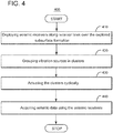
- Figure 4 illustrates a method 400 for seismic exploration of a subsurface formation, according to an embodiment.
- Method 400 includes deploying seismic receivers (e.g., 320) along receiver lines (e.g., 322, 324, 326) over the explored subsurface formation, at 410.
- Step 410 may be performed in preparation for a seismic survey.
- the receivers are left on the ground for months or even years between successive surveys of a target area.
- Method 400 further includes grouping vibratory sources in clusters, at 420.
- each cluster e.g., 350
- each cluster includes plural vibratory sources (e.g., cluster 350 includes a first vibratory source 330 and a second vibratory source 331) that are placed within a predetermined distance from one another (e.g., 25 m).
- a predetermined distance is less than an average distance between adjacent receiver lines such that the same receivers detect reflections of seismic vibration due to the vibratory sources in the same cluster.
- Method 400 further includes actuating the clusters cyclically, at 430.
- each cluster is actuated once.
- the vibratory sources pertaining to a cluster vibrate during a substantially same sweep time (i.e., as previously discussed, short static time differences much smaller than the sweep time are considered insignificant).
- the seismic vibrations produced by the vibratory sources in the same cluster are encoded to enable separation of recorded seismic data into subsets, each subset corresponding to one or more of the seismic vibrations.
- the seismic vibrations may be encoded by one of short time static differences, different constant phases, a combination of time and phase differences, etc.
- a 1 (t) and A 1 (t) are maxim amplitude of the first and second vibrations, respectively
- f 1 (t) and f 2 (t) represent individual sweeps (i.e., frequency variation with time for the respective source)
- t is time
- t 01 and t 02 are start times of the first and second vibrations, respectively
- Figure 5 illustrates source phases in successive cycles 550-554 for cluster 350, and successive cycles 560-568 for cluster 352.
- vibrations generated by sources 330 and 332 are considered to be reference vibrations (i.e., having 0° phases)
- the vibrations generated by sources 331 and 333 have randomly +90° or -90° phase in the respective successive cycles.
- the phase difference between the first and second seismic vibrations changes sign randomly in each cycle as illustrated in Figure 5 .
- the sign of the phase difference between the first and second seismic vibrations may regularly alternate between +90° or -90° from one cycle to a next cycle.
- source phases may rotate, taking, for example, values of 120 0 0 ⁇ 120 0 ⁇ 120 0 0 120 for three consecutive shot locations (i.e., the constant phases are pre-determined according to geographical shot locations).
- each line corresponds to a successive vibration of the clustered sources.
- Figures 3 and 5 illustrate clusters having the same number (2) of sources. This is an illustration and not a limitation. For example, one embodiment may include clusters having different numbers of sources and more than two sources. Moreover, in one embodiment, individual sources grouped together in clusters may vary from cycle to cycle (e.g., in a cycle, a vibratory source is clustered with an adjacent vibratory source positioned at left relative to a source's moving direction, and, then, in a next cycle, the vibratory source is clustered with an adjacent source positioned at right relative to the source's moving direction).
- cycle to cycle e.g., in a cycle, a vibratory source is clustered with an adjacent vibratory source positioned at left relative to a source's moving direction, and, then, in a next cycle, the vibratory source is clustered with an adjacent source positioned at right relative to the source's moving direction).
- each vibratory source is moved from a vibration point to a next vibration point during each cycle (i.e., unlike in U.S. Patent No. 7,050,356 where data for multiple repeated sweeps with different parameters are acquired to perform such a separation).
- the clustered sources may be selected to be as close as possible from one another.
- no vibratory source of a cluster may be intercalated between vibratory sources of any other cluster.
- the clusters may be activated at one of a series of times defined relative to the beginning of the cycle. The time intervals between successive times in the series may be substantially equal. In one embodiment, the clusters are activated in the same order in each cycle. In another embodiment, the clusters are activated in a different order in successive cycles (granted that sources in a cluster have time to move to new vibration points before being re-activated in a new cycle).
- the above embodiments of simultaneous activation of clustered sources that are physically close may be combined with the slip-sweep method.
- at least one of the clusters starts vibrating before the end of seismic receivers' listening time for a previously actuated cluster.
- the acquired seismic data may be processed first to extract individual cluster seismic data.
- an algorithm similar to the one described in U.S. Patent No. 8,451,686 (HPVA) may be used to extract the individual cluster seismic data.
- HPVA U.S. Patent No. 8,451,686
- the resulting individual cluster seismic data is then processed to separate the first data and the second data.
- a sweep of the clustered vibratory sources includes (A) a first period during which the first vibratory source and the second vibratory source in the same cluster have the same phase and vibrate with low frequencies less than or equal to a threshold frequency, and (B) a second period during which the first vibratory source and the second vibratory source have different phases and vibrate with frequencies higher than the threshold frequency.
- the seismic vibrations produced by different clustered seismic sources are then encoded to enable separation of seismic data corresponding to individual seismic vibrations at the frequencies higher than the threshold frequency.
- the seismic vibrations emitted by different clustered sources may be encoded by one of short time static differences, different constant phases, and a combination of time and phase differences.
- seismic vibrations emitted by different clustered sources have different constant phases, but phase differences may change randomly in each shooting cycle.
- Figure 6 illustrates a method 600 for seismic exploration of a subsurface formation according to another embodiment.
- Method 600 includes actuating simultaneously vibratory sources placed less than 30 m from one another, at 610. Individual seismic vibrations produced by each of the vibratory sources are encoded to enable separation of individual seismic data corresponding to individual seismic vibrations. The individual seismic vibrations are encoded by one of short time static differences, different constant phases, and a combination of time and phase differences.
- Method 600 further includes acquiring seismic data at 620.
- controller 370 which is configured to cluster the vibratory sources and to actuate them, may be a combination of software and hardware as illustrated in Figure 7 .
- Hardware, firmware, software or a combination thereof may be used to perform the various steps and operations.
- Controller 700 which may also be carried by a truck, may include server 701 having a central processor unit (CPU) 702 coupled to a random access memory (RAM) 704 and to a read-only memory (ROM) 706.
- the ROM 706 may also be other types of storage media to store programs, such as programmable ROM (PROM), erasable PROM (EPROM), etc.
- PROM programmable ROM
- EPROM erasable PROM
- Methods for clustering and actuating vibratory sources according to various embodiments described in this section may be implemented as computer programs (i.e., executable codes) non-transitorily stored on RAM 704 or ROM 706.
- Processor 702 may communicate with other internal and external components through input/output (I/O) circuitry 708 and bussing 710, to provide control signals and the like.
- processor 702 may communicate with the sensors, electro-magnetic actuator system and/or the pressure mechanism of each source element.
- Processor 702 carries out a variety of functions as are known in the art, as dictated by software and/or firmware instructions.
- Server 701 may also include one or more data storage devices, including disk drives 712, CD-ROM drives 714, and other hardware capable of reading and/or storing information, such as a DVD, etc.
- software for carrying out the above-discussed steps may be stored and distributed on a CD-ROM 716, removable media 718 or other form of media capable of storing information.
- the storage media may be inserted into, and read by, devices such as the CD-ROM drive 714, disk drive 712, etc.
- Server 701 may be coupled to a display 720, which may be any type of known display or presentation screen, such as LCD, plasma displays, cathode ray tubes (CRT), etc.
- Server 701 may control display 720 to exhibit images based on the acquired seismic data.
- a user input interface 722 is provided and may include one or more user interface mechanisms such as a mouse, keyboard, microphone, touch pad, touch screen, voice-recognition system, etc.
- Server 701 may be coupled to other computing devices, via a network.
- the server may be part of a larger network configuration as in a global area network (GAN) such as the Internet 728, which allows ultimate connection to the sources, receivers, data storage unit, etc.
- GAN global area network
Landscapes
- Engineering & Computer Science (AREA)
- Remote Sensing (AREA)
- Physics & Mathematics (AREA)
- Life Sciences & Earth Sciences (AREA)
- Acoustics & Sound (AREA)
- Environmental & Geological Engineering (AREA)
- Geology (AREA)
- General Life Sciences & Earth Sciences (AREA)
- General Physics & Mathematics (AREA)
- Geophysics (AREA)
- Geophysics And Detection Of Objects (AREA)
Claims (14)
- Verfahren (400) zur seismischen Untersuchung einer Untergrundformation, wobei das Verfahren Folgendes umfasst:Einsetzen (410) von seismischen Empfängern (320) entlang von Empfängerlinien (322, 324, 326) über der untersuchten Untergrundformation;Gruppieren (420) von Vibrationsquellen (330 - 341) in Bündeln (350 - 360); undcyclisches Betätigen (430) der Bündel, sodass in jedem Zyklus die Vibrationsquellen innerhalb eines der Bündel während einer im Wesentlichen gleichen Sweepzeit vibrieren, dadurch gekennzeichnet, dassdie Empfängerlinien durch einen durchschnittlichen Abstand benachbart und getrennt sind,dadurch, dass mindestens eines der Bündel mehrere Vibrationsquellen einschließt, die in weniger als einem vorbestimmten Abstand voneinander platziert sind, während sie vibrieren, wobei der vorbestimmte Abstand weniger als der durchschnittliche Abstand ist,und dadurch, dass Vibrationen, erzeugt von den Vibrationsquellen, die zu dem mindestens einen der Bündel gehören, codiert werden, um eine Trennung von aufgezeichneten seismischen Daten in Untereinheiten zu ermöglichen, die jeder der Vibrationsquellen entsprechen, die zu dem mindestens einen der Bündel gehören.
- Verfahren nach Anspruch 1, wobei jede der Vibrationsquellen während jedes Zyklus von einem Vibrationspunkt zu einem nächsten Vibrationspunkt bewegt wird.
- Verfahren nach Anspruch 1, wobei die Vibrationen der Vibrationsquellen, die zu dem mindestens einen der Bündel gehören, durch eines von statischen Kurzzeitdifferenzen, verschiedenen konstanten Phasen und einer Kombination von Zeit- und Phasendifferenzen codiert sind.
- Verfahren nach Anspruch 1, wobei Vibrationen der Vibrationsquellen, die zu dem mindestens einen der Bündel gehören, konstante Phasen aufweisen, die gemäß geographischen Aufnahmepunkten vorbestimmt sind.
- Verfahren nach Anspruch 1, wobei die Vibrationsquellen, die zu dem mindestens einen der Bündel gehören, gemäß einem gleichen Sweepmuster vibrieren.
- Verfahren nach Anspruch 1, wobei keine Vibrationsquelle, die zu dem mindestens einen der Bündel gehört, zwischen den Vibrationsquellen eines anderen der Bündel geschaltet wird.
- Verfahren nach Anspruch 1, weiter umfassend:Erfassen der aufgezeichneten seismischen Daten unter Verwendung der seismischen Empfänger; undTrennen der aufgezeichneten seismischen Daten in die Unterelemente, so dass jedes Unterelement einer der Vibrationsquellen entspricht.
- Verfahren nach Anspruch 1, wobei die Bündel in jedem Zyklus in der gleichen Reihenfolge aktiviert werden.
- Verfahren nach Anspruch 1, wobei mindestens eines der Bündel zu vibrieren beginnt, bevor eine Abhörzeit, die einem zuvor betätigten Bündel entspricht, geendet hat.
- Verfahren nach Anspruch 1,
wobei die Bündel cyclisch betätigt werden, um seismische Vibrationen zu erzeugen, die sich in der Untergrundformation fortsetzen, so dass in jedem Zyklus die verschiedenen Vibrationsquellen in dem mindestens einen der Bündel während einer im Wesentlichen gleichen Sweepzeit vibrieren, um seismische Vibrationen zu erzeugen, die codiert sind, um für Vibrationsfrequenzen über einer Schwellenfrequenz die Trennung von aufgezeichneten seismischen Daten in Unterelemente, die jeder der Vibrationsquellen entsprechen, zu ermöglichen. - Verfahren nach Anspruch 10, wobei
die Sweepzeit einen ersten Zeitraum (A) einschließt, währen dessen die verschiedenen Vibrationsquellen gleichzeitig mit einer oder mehreren niedrigen Frequenzen vibrieren, die kleiner oder gleich der Schwellenfrequenz sind, und (B) einem zweiten Zeitraum, während dessen die verschiedenen Vibrationsquellen codiert werden und mit Vibrationsfrequenzen vibrieren, die höher als die Schwellenfrequenz sind, und
die Schwellenfrequenz einer Wellenlänge entspricht, die den vorbestimmten Abstand übersteigt. - Verfahren nach Anspruch 11, wobei während des zweiten Zeitraums die verschiedenen seismischen Vibrationen durch eines von statischen Kurzzeitdifferenzen, verschiedenen konstanten Phasen und einer Kombination von Zeit- und Phasendifferenzen codiert werden.
- Verfahren nach Anspruch 11, wobei während des zweiten Zeitraums die seismischen Vibrationen konstante Phasen aufweisen, die gemäß den geographischen Aufnahmepunkten vorbestimmt sind.
- Verfahren nach Anspruch 10, wobei mindestens eines der Bündel vor einer Abhörzeit zu vibrieren beginnt, während der die seismischen Empfänger seismische Reflektionen aufgrund dessen abzuhören, dass eine zuvor betätigtes Bündel geendet hat.
Priority Applications (1)
| Application Number | Priority Date | Filing Date | Title |
|---|---|---|---|
| PL14720156T PL2992359T3 (pl) | 2013-05-01 | 2014-04-30 | Urządzenie i sposób do pozyskiwania danych sejsmicznych z jednoczesną aktywacją sklastrowanych wibratorów |
Applications Claiming Priority (2)
| Application Number | Priority Date | Filing Date | Title |
|---|---|---|---|
| US201361818002P | 2013-05-01 | 2013-05-01 | |
| PCT/EP2014/058825 WO2014177614A2 (en) | 2013-05-01 | 2014-04-30 | Apparatus and method for seismic data acquisition with simultaneous activation of clustered vibrators |
Publications (2)
| Publication Number | Publication Date |
|---|---|
| EP2992359A2 EP2992359A2 (de) | 2016-03-09 |
| EP2992359B1 true EP2992359B1 (de) | 2020-10-14 |
Family
ID=50624598
Family Applications (1)
| Application Number | Title | Priority Date | Filing Date |
|---|---|---|---|
| EP14720156.0A Active EP2992359B1 (de) | 2013-05-01 | 2014-04-30 | Vorrichtung und verfahren zur erfassung seismischer daten mit gleichzeitiger aktivierung von gebündelten vibratoren |
Country Status (5)
| Country | Link |
|---|---|
| US (1) | US9791578B2 (de) |
| EP (1) | EP2992359B1 (de) |
| ES (1) | ES2838696T3 (de) |
| PL (1) | PL2992359T3 (de) |
| WO (1) | WO2014177614A2 (de) |
Families Citing this family (5)
| Publication number | Priority date | Publication date | Assignee | Title |
|---|---|---|---|---|
| JP6347480B2 (ja) * | 2014-05-27 | 2018-06-27 | 独立行政法人石油天然ガス・金属鉱物資源機構 | 振動検出システム、信号処理装置及び信号処理方法 |
| GB2565336A (en) * | 2017-08-10 | 2019-02-13 | Seismic Apparition Gmbh | Method for seismic data acquisition and processing |
| WO2019060701A1 (en) * | 2017-09-22 | 2019-03-28 | Westerngeco Llc | METHODS AND SYSTEMS FOR CONCRETE TERRESTRIAL VIBROSISMIC ACQUISITION WITH SIMULTANEOUS ACTIVATION |
| US11828895B2 (en) | 2019-08-05 | 2023-11-28 | Geosoftware C.V. | Methods and devices using effective elastic parameter values for anisotropic media |
| US20250347818A1 (en) * | 2024-05-13 | 2025-11-13 | Schlumberger Technology Corporation | Seismic imaging framework |
Family Cites Families (9)
| Publication number | Priority date | Publication date | Assignee | Title |
|---|---|---|---|---|
| US4715020A (en) * | 1986-10-29 | 1987-12-22 | Western Atlas International, Inc. | Simultaneous performance of multiple seismic vibratory surveys |
| US6603707B1 (en) | 2002-02-26 | 2003-08-05 | Compagnie Generale De Geophysique | Method of reducing harmonic noise in vibroseis operations |
| GB2387226C (en) | 2002-04-06 | 2008-05-12 | Westerngeco Ltd | A method of seismic surveying |
| FR2845484B1 (fr) | 2002-10-08 | 2005-03-11 | Inst Francais Du Petrole | Methode de separation de signaux de microsismicite de signaux sismiques emis par une ou plusieurs sources |
| FR2890177B1 (fr) | 2005-09-01 | 2007-11-02 | Cie Generale De Geophysique Sa | Procede et systeme d'acquisition de donnees sismiques |
| FR2941055B1 (fr) | 2009-01-12 | 2011-02-25 | Cggveritas Services Sa | Procede d'acquisition de donnees vibrosismiques concernant une zone du sous-sol, et procede d'exploration sismique incluant un tel procede |
| US20110305105A1 (en) | 2010-06-09 | 2011-12-15 | Timothy James Dean | Controlling seismic sources in connection with a seismic survey |
| US8588027B2 (en) | 2010-07-12 | 2013-11-19 | Westerngeco L.L.C. | Vibroseis acquisition technique and system using dynamic source control |
| US9588241B2 (en) | 2011-05-13 | 2017-03-07 | Saudi Arabian Oil Company | Frequency-varying filtering of simultaneous source seismic data |
-
2014
- 2014-04-30 US US14/786,132 patent/US9791578B2/en active Active
- 2014-04-30 WO PCT/EP2014/058825 patent/WO2014177614A2/en not_active Ceased
- 2014-04-30 PL PL14720156T patent/PL2992359T3/pl unknown
- 2014-04-30 EP EP14720156.0A patent/EP2992359B1/de active Active
- 2014-04-30 ES ES14720156T patent/ES2838696T3/es active Active
Non-Patent Citations (1)
| Title |
|---|
| None * |
Also Published As
| Publication number | Publication date |
|---|---|
| PL2992359T3 (pl) | 2021-04-19 |
| ES2838696T3 (es) | 2021-07-02 |
| US9791578B2 (en) | 2017-10-17 |
| EP2992359A2 (de) | 2016-03-09 |
| US20160077226A1 (en) | 2016-03-17 |
| WO2014177614A3 (en) | 2015-03-19 |
| WO2014177614A2 (en) | 2014-11-06 |
Similar Documents
| Publication | Publication Date | Title |
|---|---|---|
| US11698472B2 (en) | Method and system for separating seismic sources in marine simultaneous shooting acquisition | |
| Morgan et al. | Next-generation seismic experiments: wide-angle, multi-azimuth, three-dimensional, full-waveform inversion | |
| EP2372400B1 (de) | Verfahren zur Abbildung des Erduntergrundes während mariner seismischer Datenerfassung | |
| US9411062B2 (en) | Method and system for determining source signatures after source ghost removal | |
| EP2108980B1 (de) | Verfahren zur Unterdrückung von Oberflächenreflexionen bei marinen seismischen Streamerdaten mit irregulären Empfängerpositionen | |
| CA3113994C (en) | Spatially locating a microseismic event utilizing an acoustic sensing cable | |
| EP2992359B1 (de) | Vorrichtung und verfahren zur erfassung seismischer daten mit gleichzeitiger aktivierung von gebündelten vibratoren | |
| EP2081054A2 (de) | Verfahren zur Wellenfeldtrennung in 3D-Doppelsensorgebundenen Streamer-Daten mit Alias-Energie in quer zum Streamer verlaufender Richtung | |
| EA036782B1 (ru) | Способ и устройство для сейсмической съемки | |
| WO2013076572A2 (en) | Seismic receivers as seismic sources | |
| US20160231442A1 (en) | Optimal phase relationship | |
| CA3106943A1 (en) | Fast plane-wave reverse time migration | |
| US10261202B2 (en) | Device and method for mitigating seismic survey interference | |
| Tertyshnikov et al. | Seismic Monitoring of CO2 migration through a shallow fault |
Legal Events
| Date | Code | Title | Description |
|---|---|---|---|
| PUAI | Public reference made under article 153(3) epc to a published international application that has entered the european phase |
Free format text: ORIGINAL CODE: 0009012 |
|
| 17P | Request for examination filed |
Effective date: 20151019 |
|
| AK | Designated contracting states |
Kind code of ref document: A2 Designated state(s): AL AT BE BG CH CY CZ DE DK EE ES FI FR GB GR HR HU IE IS IT LI LT LU LV MC MK MT NL NO PL PT RO RS SE SI SK SM TR |
|
| AX | Request for extension of the european patent |
Extension state: BA ME |
|
| DAX | Request for extension of the european patent (deleted) | ||
| STAA | Information on the status of an ep patent application or granted ep patent |
Free format text: STATUS: EXAMINATION IS IN PROGRESS |
|
| 17Q | First examination report despatched |
Effective date: 20180313 |
|
| GRAP | Despatch of communication of intention to grant a patent |
Free format text: ORIGINAL CODE: EPIDOSNIGR1 |
|
| STAA | Information on the status of an ep patent application or granted ep patent |
Free format text: STATUS: GRANT OF PATENT IS INTENDED |
|
| RIN1 | Information on inventor provided before grant (corrected) |
Inventor name: WINTER, OLIVIER Inventor name: BIANCHI, THOMAS Inventor name: MEUNIER, JULIEN |
|
| INTG | Intention to grant announced |
Effective date: 20200422 |
|
| GRAJ | Information related to disapproval of communication of intention to grant by the applicant or resumption of examination proceedings by the epo deleted |
Free format text: ORIGINAL CODE: EPIDOSDIGR1 |
|
| STAA | Information on the status of an ep patent application or granted ep patent |
Free format text: STATUS: EXAMINATION IS IN PROGRESS |
|
| RAP1 | Party data changed (applicant data changed or rights of an application transferred) |
Owner name: CGG SERVICES SAS |
|
| GRAP | Despatch of communication of intention to grant a patent |
Free format text: ORIGINAL CODE: EPIDOSNIGR1 |
|
| STAA | Information on the status of an ep patent application or granted ep patent |
Free format text: STATUS: GRANT OF PATENT IS INTENDED |
|
| INTC | Intention to grant announced (deleted) | ||
| INTG | Intention to grant announced |
Effective date: 20200706 |
|
| GRAS | Grant fee paid |
Free format text: ORIGINAL CODE: EPIDOSNIGR3 |
|
| GRAA | (expected) grant |
Free format text: ORIGINAL CODE: 0009210 |
|
| STAA | Information on the status of an ep patent application or granted ep patent |
Free format text: STATUS: THE PATENT HAS BEEN GRANTED |
|
| AK | Designated contracting states |
Kind code of ref document: B1 Designated state(s): AL AT BE BG CH CY CZ DE DK EE ES FI FR GB GR HR HU IE IS IT LI LT LU LV MC MK MT NL NO PL PT RO RS SE SI SK SM TR |
|
| REG | Reference to a national code |
Ref country code: GB Ref legal event code: FG4D |
|
| REG | Reference to a national code |
Ref country code: AT Ref legal event code: REF Ref document number: 1324126 Country of ref document: AT Kind code of ref document: T Effective date: 20201015 Ref country code: CH Ref legal event code: EP |
|
| REG | Reference to a national code |
Ref country code: DE Ref legal event code: R096 Ref document number: 602014071205 Country of ref document: DE |
|
| REG | Reference to a national code |
Ref country code: IE Ref legal event code: FG4D |
|
| REG | Reference to a national code |
Ref country code: NL Ref legal event code: FP |
|
| REG | Reference to a national code |
Ref country code: GR Ref legal event code: EP Ref document number: 20210400032 Country of ref document: GR Effective date: 20210215 |
|
| REG | Reference to a national code |
Ref country code: AT Ref legal event code: MK05 Ref document number: 1324126 Country of ref document: AT Kind code of ref document: T Effective date: 20201014 |
|
| PG25 | Lapsed in a contracting state [announced via postgrant information from national office to epo] |
Ref country code: PT Free format text: LAPSE BECAUSE OF FAILURE TO SUBMIT A TRANSLATION OF THE DESCRIPTION OR TO PAY THE FEE WITHIN THE PRESCRIBED TIME-LIMIT Effective date: 20210215 Ref country code: NO Free format text: LAPSE BECAUSE OF FAILURE TO SUBMIT A TRANSLATION OF THE DESCRIPTION OR TO PAY THE FEE WITHIN THE PRESCRIBED TIME-LIMIT Effective date: 20210114 Ref country code: FI Free format text: LAPSE BECAUSE OF FAILURE TO SUBMIT A TRANSLATION OF THE DESCRIPTION OR TO PAY THE FEE WITHIN THE PRESCRIBED TIME-LIMIT Effective date: 20201014 Ref country code: RS Free format text: LAPSE BECAUSE OF FAILURE TO SUBMIT A TRANSLATION OF THE DESCRIPTION OR TO PAY THE FEE WITHIN THE PRESCRIBED TIME-LIMIT Effective date: 20201014 |
|
| REG | Reference to a national code |
Ref country code: LT Ref legal event code: MG4D |
|
| PG25 | Lapsed in a contracting state [announced via postgrant information from national office to epo] |
Ref country code: SE Free format text: LAPSE BECAUSE OF FAILURE TO SUBMIT A TRANSLATION OF THE DESCRIPTION OR TO PAY THE FEE WITHIN THE PRESCRIBED TIME-LIMIT Effective date: 20201014 Ref country code: LV Free format text: LAPSE BECAUSE OF FAILURE TO SUBMIT A TRANSLATION OF THE DESCRIPTION OR TO PAY THE FEE WITHIN THE PRESCRIBED TIME-LIMIT Effective date: 20201014 Ref country code: IS Free format text: LAPSE BECAUSE OF FAILURE TO SUBMIT A TRANSLATION OF THE DESCRIPTION OR TO PAY THE FEE WITHIN THE PRESCRIBED TIME-LIMIT Effective date: 20210214 Ref country code: AT Free format text: LAPSE BECAUSE OF FAILURE TO SUBMIT A TRANSLATION OF THE DESCRIPTION OR TO PAY THE FEE WITHIN THE PRESCRIBED TIME-LIMIT Effective date: 20201014 Ref country code: BG Free format text: LAPSE BECAUSE OF FAILURE TO SUBMIT A TRANSLATION OF THE DESCRIPTION OR TO PAY THE FEE WITHIN THE PRESCRIBED TIME-LIMIT Effective date: 20210114 |
|
| PG25 | Lapsed in a contracting state [announced via postgrant information from national office to epo] |
Ref country code: HR Free format text: LAPSE BECAUSE OF FAILURE TO SUBMIT A TRANSLATION OF THE DESCRIPTION OR TO PAY THE FEE WITHIN THE PRESCRIBED TIME-LIMIT Effective date: 20201014 |
|
| REG | Reference to a national code |
Ref country code: ES Ref legal event code: FG2A Ref document number: 2838696 Country of ref document: ES Kind code of ref document: T3 Effective date: 20210702 |
|
| REG | Reference to a national code |
Ref country code: DE Ref legal event code: R097 Ref document number: 602014071205 Country of ref document: DE |
|
| PG25 | Lapsed in a contracting state [announced via postgrant information from national office to epo] |
Ref country code: RO Free format text: LAPSE BECAUSE OF FAILURE TO SUBMIT A TRANSLATION OF THE DESCRIPTION OR TO PAY THE FEE WITHIN THE PRESCRIBED TIME-LIMIT Effective date: 20201014 Ref country code: SK Free format text: LAPSE BECAUSE OF FAILURE TO SUBMIT A TRANSLATION OF THE DESCRIPTION OR TO PAY THE FEE WITHIN THE PRESCRIBED TIME-LIMIT Effective date: 20201014 Ref country code: LT Free format text: LAPSE BECAUSE OF FAILURE TO SUBMIT A TRANSLATION OF THE DESCRIPTION OR TO PAY THE FEE WITHIN THE PRESCRIBED TIME-LIMIT Effective date: 20201014 Ref country code: CZ Free format text: LAPSE BECAUSE OF FAILURE TO SUBMIT A TRANSLATION OF THE DESCRIPTION OR TO PAY THE FEE WITHIN THE PRESCRIBED TIME-LIMIT Effective date: 20201014 Ref country code: EE Free format text: LAPSE BECAUSE OF FAILURE TO SUBMIT A TRANSLATION OF THE DESCRIPTION OR TO PAY THE FEE WITHIN THE PRESCRIBED TIME-LIMIT Effective date: 20201014 Ref country code: SM Free format text: LAPSE BECAUSE OF FAILURE TO SUBMIT A TRANSLATION OF THE DESCRIPTION OR TO PAY THE FEE WITHIN THE PRESCRIBED TIME-LIMIT Effective date: 20201014 |
|
| PLBE | No opposition filed within time limit |
Free format text: ORIGINAL CODE: 0009261 |
|
| STAA | Information on the status of an ep patent application or granted ep patent |
Free format text: STATUS: NO OPPOSITION FILED WITHIN TIME LIMIT |
|
| PG25 | Lapsed in a contracting state [announced via postgrant information from national office to epo] |
Ref country code: DK Free format text: LAPSE BECAUSE OF FAILURE TO SUBMIT A TRANSLATION OF THE DESCRIPTION OR TO PAY THE FEE WITHIN THE PRESCRIBED TIME-LIMIT Effective date: 20201014 |
|
| 26N | No opposition filed |
Effective date: 20210715 |
|
| PG25 | Lapsed in a contracting state [announced via postgrant information from national office to epo] |
Ref country code: AL Free format text: LAPSE BECAUSE OF FAILURE TO SUBMIT A TRANSLATION OF THE DESCRIPTION OR TO PAY THE FEE WITHIN THE PRESCRIBED TIME-LIMIT Effective date: 20201014 |
|
| PG25 | Lapsed in a contracting state [announced via postgrant information from national office to epo] |
Ref country code: SI Free format text: LAPSE BECAUSE OF FAILURE TO SUBMIT A TRANSLATION OF THE DESCRIPTION OR TO PAY THE FEE WITHIN THE PRESCRIBED TIME-LIMIT Effective date: 20201014 Ref country code: MC Free format text: LAPSE BECAUSE OF FAILURE TO SUBMIT A TRANSLATION OF THE DESCRIPTION OR TO PAY THE FEE WITHIN THE PRESCRIBED TIME-LIMIT Effective date: 20201014 |
|
| PG25 | Lapsed in a contracting state [announced via postgrant information from national office to epo] |
Ref country code: LU Free format text: LAPSE BECAUSE OF NON-PAYMENT OF DUE FEES Effective date: 20210430 |
|
| PG25 | Lapsed in a contracting state [announced via postgrant information from national office to epo] |
Ref country code: LI Free format text: LAPSE BECAUSE OF NON-PAYMENT OF DUE FEES Effective date: 20210430 Ref country code: CH Free format text: LAPSE BECAUSE OF NON-PAYMENT OF DUE FEES Effective date: 20210430 |
|
| PG25 | Lapsed in a contracting state [announced via postgrant information from national office to epo] |
Ref country code: IE Free format text: LAPSE BECAUSE OF NON-PAYMENT OF DUE FEES Effective date: 20210430 |
|
| PG25 | Lapsed in a contracting state [announced via postgrant information from national office to epo] |
Ref country code: IS Free format text: LAPSE BECAUSE OF FAILURE TO SUBMIT A TRANSLATION OF THE DESCRIPTION OR TO PAY THE FEE WITHIN THE PRESCRIBED TIME-LIMIT Effective date: 20210214 |
|
| REG | Reference to a national code |
Ref country code: GB Ref legal event code: 732E Free format text: REGISTERED BETWEEN 20220721 AND 20220727 |
|
| PG25 | Lapsed in a contracting state [announced via postgrant information from national office to epo] |
Ref country code: HU Free format text: LAPSE BECAUSE OF FAILURE TO SUBMIT A TRANSLATION OF THE DESCRIPTION OR TO PAY THE FEE WITHIN THE PRESCRIBED TIME-LIMIT; INVALID AB INITIO Effective date: 20140430 |
|
| PG25 | Lapsed in a contracting state [announced via postgrant information from national office to epo] |
Ref country code: CY Free format text: LAPSE BECAUSE OF FAILURE TO SUBMIT A TRANSLATION OF THE DESCRIPTION OR TO PAY THE FEE WITHIN THE PRESCRIBED TIME-LIMIT Effective date: 20201014 |
|
| PG25 | Lapsed in a contracting state [announced via postgrant information from national office to epo] |
Ref country code: MK Free format text: LAPSE BECAUSE OF FAILURE TO SUBMIT A TRANSLATION OF THE DESCRIPTION OR TO PAY THE FEE WITHIN THE PRESCRIBED TIME-LIMIT Effective date: 20201014 |
|
| PG25 | Lapsed in a contracting state [announced via postgrant information from national office to epo] |
Ref country code: MT Free format text: LAPSE BECAUSE OF FAILURE TO SUBMIT A TRANSLATION OF THE DESCRIPTION OR TO PAY THE FEE WITHIN THE PRESCRIBED TIME-LIMIT Effective date: 20201014 |
|
| PGFP | Annual fee paid to national office [announced via postgrant information from national office to epo] |
Ref country code: NL Payment date: 20250418 Year of fee payment: 12 |
|
| PGFP | Annual fee paid to national office [announced via postgrant information from national office to epo] |
Ref country code: PL Payment date: 20250418 Year of fee payment: 12 Ref country code: DE Payment date: 20250422 Year of fee payment: 12 |
|
| PGFP | Annual fee paid to national office [announced via postgrant information from national office to epo] |
Ref country code: ES Payment date: 20250529 Year of fee payment: 12 |
|
| PGFP | Annual fee paid to national office [announced via postgrant information from national office to epo] |
Ref country code: IT Payment date: 20250424 Year of fee payment: 12 Ref country code: BE Payment date: 20250418 Year of fee payment: 12 |
|
| PGFP | Annual fee paid to national office [announced via postgrant information from national office to epo] |
Ref country code: FR Payment date: 20250425 Year of fee payment: 12 |
|
| PGFP | Annual fee paid to national office [announced via postgrant information from national office to epo] |
Ref country code: GR Payment date: 20250423 Year of fee payment: 12 |
|
| PG25 | Lapsed in a contracting state [announced via postgrant information from national office to epo] |
Ref country code: TR Free format text: LAPSE BECAUSE OF FAILURE TO SUBMIT A TRANSLATION OF THE DESCRIPTION OR TO PAY THE FEE WITHIN THE PRESCRIBED TIME-LIMIT Effective date: 20201014 |
|
| PGFP | Annual fee paid to national office [announced via postgrant information from national office to epo] |
Ref country code: GB Payment date: 20260312 Year of fee payment: 13 |