EP2992242B1 - Hydraulic engine mount inertia track with at least two restrictions - Google Patents
Hydraulic engine mount inertia track with at least two restrictions Download PDFInfo
- Publication number
- EP2992242B1 EP2992242B1 EP14791469.1A EP14791469A EP2992242B1 EP 2992242 B1 EP2992242 B1 EP 2992242B1 EP 14791469 A EP14791469 A EP 14791469A EP 2992242 B1 EP2992242 B1 EP 2992242B1
- Authority
- EP
- European Patent Office
- Prior art keywords
- inertia track
- channel
- protrusion
- engine mount
- restrictions
- Prior art date
- Legal status (The legal status is an assumption and is not a legal conclusion. Google has not performed a legal analysis and makes no representation as to the accuracy of the status listed.)
- Active
Links
- 239000012530 fluid Substances 0.000 claims description 19
- 230000007423 decrease Effects 0.000 description 3
- 239000004033 plastic Substances 0.000 description 3
- 239000000463 material Substances 0.000 description 2
- 229920000642 polymer Polymers 0.000 description 2
- XAGFODPZIPBFFR-UHFFFAOYSA-N aluminium Chemical compound [Al] XAGFODPZIPBFFR-UHFFFAOYSA-N 0.000 description 1
- 229910052782 aluminium Inorganic materials 0.000 description 1
- 230000003247 decreasing effect Effects 0.000 description 1
- 239000000203 mixture Substances 0.000 description 1
Images


Classifications
-
- F—MECHANICAL ENGINEERING; LIGHTING; HEATING; WEAPONS; BLASTING
- F16—ENGINEERING ELEMENTS AND UNITS; GENERAL MEASURES FOR PRODUCING AND MAINTAINING EFFECTIVE FUNCTIONING OF MACHINES OR INSTALLATIONS; THERMAL INSULATION IN GENERAL
- F16F—SPRINGS; SHOCK-ABSORBERS; MEANS FOR DAMPING VIBRATION
- F16F13/00—Units comprising springs of the non-fluid type as well as vibration-dampers, shock-absorbers, or fluid springs
- F16F13/04—Units comprising springs of the non-fluid type as well as vibration-dampers, shock-absorbers, or fluid springs comprising both a plastics spring and a damper, e.g. a friction damper
- F16F13/06—Units comprising springs of the non-fluid type as well as vibration-dampers, shock-absorbers, or fluid springs comprising both a plastics spring and a damper, e.g. a friction damper the damper being a fluid damper, e.g. the plastics spring not forming a part of the wall of the fluid chamber of the damper
- F16F13/08—Units comprising springs of the non-fluid type as well as vibration-dampers, shock-absorbers, or fluid springs comprising both a plastics spring and a damper, e.g. a friction damper the damper being a fluid damper, e.g. the plastics spring not forming a part of the wall of the fluid chamber of the damper the plastics spring forming at least a part of the wall of the fluid chamber of the damper
- F16F13/10—Units comprising springs of the non-fluid type as well as vibration-dampers, shock-absorbers, or fluid springs comprising both a plastics spring and a damper, e.g. a friction damper the damper being a fluid damper, e.g. the plastics spring not forming a part of the wall of the fluid chamber of the damper the plastics spring forming at least a part of the wall of the fluid chamber of the damper the wall being at least in part formed by a flexible membrane or the like
- F16F13/105—Units comprising springs of the non-fluid type as well as vibration-dampers, shock-absorbers, or fluid springs comprising both a plastics spring and a damper, e.g. a friction damper the damper being a fluid damper, e.g. the plastics spring not forming a part of the wall of the fluid chamber of the damper the plastics spring forming at least a part of the wall of the fluid chamber of the damper the wall being at least in part formed by a flexible membrane or the like characterised by features of partitions between two working chambers
- F16F13/107—Passage design between working chambers
-
- F—MECHANICAL ENGINEERING; LIGHTING; HEATING; WEAPONS; BLASTING
- F16—ENGINEERING ELEMENTS AND UNITS; GENERAL MEASURES FOR PRODUCING AND MAINTAINING EFFECTIVE FUNCTIONING OF MACHINES OR INSTALLATIONS; THERMAL INSULATION IN GENERAL
- F16F—SPRINGS; SHOCK-ABSORBERS; MEANS FOR DAMPING VIBRATION
- F16F13/00—Units comprising springs of the non-fluid type as well as vibration-dampers, shock-absorbers, or fluid springs
- F16F13/04—Units comprising springs of the non-fluid type as well as vibration-dampers, shock-absorbers, or fluid springs comprising both a plastics spring and a damper, e.g. a friction damper
- F16F13/06—Units comprising springs of the non-fluid type as well as vibration-dampers, shock-absorbers, or fluid springs comprising both a plastics spring and a damper, e.g. a friction damper the damper being a fluid damper, e.g. the plastics spring not forming a part of the wall of the fluid chamber of the damper
- F16F13/08—Units comprising springs of the non-fluid type as well as vibration-dampers, shock-absorbers, or fluid springs comprising both a plastics spring and a damper, e.g. a friction damper the damper being a fluid damper, e.g. the plastics spring not forming a part of the wall of the fluid chamber of the damper the plastics spring forming at least a part of the wall of the fluid chamber of the damper
- F16F13/10—Units comprising springs of the non-fluid type as well as vibration-dampers, shock-absorbers, or fluid springs comprising both a plastics spring and a damper, e.g. a friction damper the damper being a fluid damper, e.g. the plastics spring not forming a part of the wall of the fluid chamber of the damper the plastics spring forming at least a part of the wall of the fluid chamber of the damper the wall being at least in part formed by a flexible membrane or the like
- F16F13/105—Units comprising springs of the non-fluid type as well as vibration-dampers, shock-absorbers, or fluid springs comprising both a plastics spring and a damper, e.g. a friction damper the damper being a fluid damper, e.g. the plastics spring not forming a part of the wall of the fluid chamber of the damper the plastics spring forming at least a part of the wall of the fluid chamber of the damper the wall being at least in part formed by a flexible membrane or the like characterised by features of partitions between two working chambers
Definitions
- the present invention relates generally to engine mounts. More particularly, the present invention relates to a hydraulic engine mount having an inertia track.
- the hydraulic engine mount assembly having an inertia track assembly often includes an elastomeric disc (decoupler) captured between the upper and lower inertia tracks (See Figure 7 illustrating the prior art).
- the inertia track is a channel filled with a hydraulic fluid moving between the upper and lower chambers of the hydraulic mount.
- the inertia track is unobstructed throughout the entire length of the track to offer the most efficient movement of fluid within the track as it enters and exits the track. Hydraulic mounts with restrictions in the inertia track are also known. One example of this is disclosed in EP 1217251 .
- a hydraulic engine mount having hydraulic fluid and including a channel where the channel has a first side wall and a second side wall, the second side wall being opposed and spaced apart from the first side wall.
- a pair of restrictions is disposed within the channel, the restrictions having a first protrusion on the first side wall of the channel, a second protrusion provided opposed and spaced apart from the first protrusion thereby restricting fluid flow through the channel to reduce pressure and noise within the channel.
- the first protrusion has a generally triangular shape having generally planar surfaces and extends into the channel and the second protrusion is curved and with a rounded point that extends into the channel.
- the restriction is disposed adjacent to an inlet within the channel. In yet another embodiment, the restriction is disposed adjacent to an outlet within the channel.
- the present invention provides for a hydraulic engine mount for dampening having an inertia track having multiple restrictions or pinch points.
- the inner surface of the inertia track is modified to create multiple points of restriction to alter the hydraulic fluid flow through the inertia track.
- the inclusion of two or more restriction points within the inertia track substantially decreases the pressure of the fluid and noise as heard by the user of the vehicle.
- the restriction points added to the inside of the inertia track influence the flow of fluid through the track such that energy is absorbed into the restriction points to reduce the transmitted force through the mount.
- the restriction points within the inertia track are generally triangle shaped or curved features protruding inward to the center of the inertia track from either side or surface of the inertia track thereby locally restricting the effective cross section for the fluid to pass through.
- the restriction points are positioned near the inlet and outlet features of the inertia track.
- Figure 1 illustrates the partial mount 20 having an inertia track (or channel).
- the mount and inertia track include an inlet allowing fluid to enter the inertia track 12 and an outlet 18 to transport fluid from a first chamber to a second chamber.
- the mount 10 further includes an outer surface 16 which may be housed in a separate housing.
- the inertia track 12 of the prior art includes a smooth inner surface without having any obstructions or restrictions. The cross-sectional dimensions of the inertia track 12 remain relatively consistent from the inlet 14 to the outlet 18.
- Figures 2-4 illustrate the partial mount 20 having an inertia track (or channel) 22 of the present invention.
- the mount 20 includes an upper surface 24 which may also be a seal.
- the inertia track 20 includes an inlet 26 and an outlet 28.
- the inlet 26 is operable to receive fluid from a first chamber. The fluid then flows through the inertia track 22 and out through the outlet 28 to a second chamber.
- the mount 20 includes an outer surface 30 and an inner rubber portion (not pictured).
- Various attachment features and apertures 34, 36 are provided to connect and align the various components of the full engine mount to one another.
- the inertia track 22 includes a first surface 35 and a second surface 38.
- the first surface 35 is the outermost surface of the inertia track 22.
- the second surface 38 is the innermost surface of the inertia track 22.
- the inertia track 22 assembly as shown in Figure 2 is made of plastic, aluminum or other suitable material.
- the assembly is made of a plastic, polymer, plastic like, rubber, or polymer like material suitable for use in the engine mount.
- the inertia track 22 includes the first surface 35 and the second surface 38. Various protrusions are included on both the first surface 35 and on the second surface 38 to create two restriction points 40, 41.
- the first restriction point 40 is positioned near the inlet 26 of the inertia track 22. The positioning of the restriction point 40 near the inlet 26 greatly reduces the overall pressure and thus noise of the engine mount.
- a second restriction point 41 is positioned at a point later down the inertia track 22 near the outlet 28 of the inertia track 20.
- the second restriction point 42 also reduces the overall fluid pressure and thus noise of the engine mount.
- the inclusion of the two restriction points 40, 41 dramatically reduces the overall noise of the engine mount. Testing has shown a significant drop in noise with the inclusion of at least two restriction points.
- the first restriction point 40 includes a first protrusion 42 and a second protrusion 46.
- the first protrusion 42 as compared to the second protrusion 46 may vary in dimension and size.
- the first protrusion 42 has a generally triangular shape having generally planar surfaces 48.
- the second protrusion 46 includes a generally curved surface protruding to the center of the inertia track 22.
- the second restriction point 41 includes a first protrusion 50 and a second protrusion 52.
- the first protrusion 50 includes a generally triangular shaped protrusion extending into the center of the inertia track 22.
- the second protrusion 52 is curved and with a rounded point extends into the inertia track 22.
- the first protrusion 50 includes generally planar surfaces 54 to create a generally triangular shape.
- the restriction points 40, 41 change the geometry of the inertia track 22. Specifically, the restriction points 40, 41 decrease the distance between the first surface 35 and the second surface 38. Throughout most of the length of the inertia track 22 the inertia track 22 includes a spaced apart distance A between the first surface 35 and the second surface 38. The distance A throughout the inertia track 22 is generally constant with the exception of a few points near the inlet 26 and the outlet 28 of the inertia track. At the restriction points 40, 41, the distance between the first surface 35 and the second surface 38 of the inertia track 22 is at a predetermined distance B. The distance B is the smallest point, thus being a restriction point, of the inertia track 22.
- the protrusions 42, 46, 50, 52 gradually decrease the distance between the first surface 35 and the second surface 38 until the distance between the first surface 35 and the second surface 38 is at a minimum at the distance B.
- This restriction point locally restricts the effective cross section for the fluid to pass through the inertia track 22.
- These restriction points 40, 41 significantly reduce noise by influencing the flow of fluid through the inertia track 22 such that energy is absorbed into the restriction points 40, 41 thereby reducing the transmitted forces throughout the engine mount. As such, at least two restriction points are required to reduce the noise level of the engine mount.
Landscapes
- Engineering & Computer Science (AREA)
- General Engineering & Computer Science (AREA)
- Mechanical Engineering (AREA)
- Arrangement Or Mounting Of Propulsion Units For Vehicles (AREA)
- Combined Devices Of Dampers And Springs (AREA)
Description
- The present invention relates generally to engine mounts. More particularly, the present invention relates to a hydraulic engine mount having an inertia track.
- It is common for hydraulic engine mounts to have an inertia track assembly having an upper inertia track and a lower inertia track. The hydraulic engine mount assembly having an inertia track assembly often includes an elastomeric disc (decoupler) captured between the upper and lower inertia tracks (See
Figure 7 illustrating the prior art). The inertia track is a channel filled with a hydraulic fluid moving between the upper and lower chambers of the hydraulic mount. The inertia track is unobstructed throughout the entire length of the track to offer the most efficient movement of fluid within the track as it enters and exits the track. Hydraulic mounts with restrictions in the inertia track are also known. One example of this is disclosed inEP 1217251 . - However, a common problem with a fluid filled engine mount inertia track is that the decoupler disc creates noise caused by the contact between the disc and the inertia track pieces. The contact of the disc also produces a force which is transferred through the mount to the attaching vehicle structure which can cause vibration and/or noise in the vehicle and heard by the user. Accordingly, there exists a need in the art to provide a hydraulic engine mount having a fluid filled inertia track with decreased vibration and noise.
- A hydraulic engine mount is provided having hydraulic fluid and including a channel where the channel has a first side wall and a second side wall, the second side wall being opposed and spaced apart from the first side wall. A pair of restrictions is disposed within the channel, the restrictions having a first protrusion on the first side wall of the channel, a second protrusion provided opposed and spaced apart from the first protrusion thereby restricting fluid flow through the channel to reduce pressure and noise within the channel. The first protrusion has a generally triangular shape having generally planar surfaces and extends into the channel and the second protrusion is curved and with a rounded point that extends into the channel. In one embodiment, the restriction is disposed adjacent to an inlet within the channel. In yet another embodiment, the restriction is disposed adjacent to an outlet within the channel.
-
-
Figure 1 illustrates a perspective view of an installed engine mount of the present invention; -
Figure 2 illustrates a perspective view of the inertia track having restriction points of the present invention; -
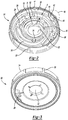
Figure 3 illustrates a perspective bottom view of the inertia track of the present invention; -
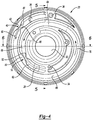
Figure 4 illustrates a top view of the inertia track of the present invention; -
Figure 5 illustrates a cross-sectional view of the inertia track along the line 5-5 ofFigure 4 ; -
Figure 6 illustrates a cross sectional view of the inertia track along the 6-6 ofFigure 4 ; and -
Figure 7 illustrates an inertia track of the prior art without any restrictions. - The present invention provides for a hydraulic engine mount for dampening having an inertia track having multiple restrictions or pinch points. The inner surface of the inertia track is modified to create multiple points of restriction to alter the hydraulic fluid flow through the inertia track. The inclusion of two or more restriction points within the inertia track substantially decreases the pressure of the fluid and noise as heard by the user of the vehicle. The restriction points added to the inside of the inertia track influence the flow of fluid through the track such that energy is absorbed into the restriction points to reduce the transmitted force through the mount. The restriction points within the inertia track are generally triangle shaped or curved features protruding inward to the center of the inertia track from either side or surface of the inertia track thereby locally restricting the effective cross section for the fluid to pass through. The restriction points are positioned near the inlet and outlet features of the inertia track.
-
Figure 1 illustrates thepartial mount 20 having an inertia track (or channel). The mount and inertia track include an inlet allowing fluid to enter theinertia track 12 and anoutlet 18 to transport fluid from a first chamber to a second chamber. Themount 10 further includes anouter surface 16 which may be housed in a separate housing. Theinertia track 12 of the prior art includes a smooth inner surface without having any obstructions or restrictions. The cross-sectional dimensions of theinertia track 12 remain relatively consistent from theinlet 14 to theoutlet 18. -
Figures 2-4 illustrate thepartial mount 20 having an inertia track (or channel) 22 of the present invention. Themount 20 includes anupper surface 24 which may also be a seal. Theinertia track 20 includes aninlet 26 and anoutlet 28. Theinlet 26 is operable to receive fluid from a first chamber. The fluid then flows through the inertia track 22 and out through theoutlet 28 to a second chamber. - The
mount 20 includes anouter surface 30 and an inner rubber portion (not pictured). Various attachment features andapertures - The inertia track 22 includes a
first surface 35 and asecond surface 38. Thefirst surface 35 is the outermost surface of the inertia track 22. Thesecond surface 38 is the innermost surface of the inertia track 22. - In the present embodiment, the inertia track 22 assembly as shown in
Figure 2 is made of plastic, aluminum or other suitable material. In alternative embodiments, the assembly is made of a plastic, polymer, plastic like, rubber, or polymer like material suitable for use in the engine mount. - The inertia track 22 includes the
first surface 35 and thesecond surface 38. Various protrusions are included on both thefirst surface 35 and on thesecond surface 38 to create tworestriction points first restriction point 40 is positioned near theinlet 26 of the inertia track 22. The positioning of therestriction point 40 near theinlet 26 greatly reduces the overall pressure and thus noise of the engine mount. - A
second restriction point 41 is positioned at a point later down the inertia track 22 near theoutlet 28 of theinertia track 20. Thesecond restriction point 42 also reduces the overall fluid pressure and thus noise of the engine mount. The inclusion of the tworestriction points - The
first restriction point 40 includes afirst protrusion 42 and asecond protrusion 46. Thefirst protrusion 42 as compared to thesecond protrusion 46 may vary in dimension and size. In the present embodiment, thefirst protrusion 42 has a generally triangular shape having generallyplanar surfaces 48. Conversely, thesecond protrusion 46 includes a generally curved surface protruding to the center of the inertia track 22. These configurations may be reversed or duplicated according to the requirements of the vehicle. - The
second restriction point 41 includes afirst protrusion 50 and asecond protrusion 52. In accordance with the arrangement of thefirst restriction point 40, thefirst protrusion 50 includes a generally triangular shaped protrusion extending into the center of the inertia track 22. Thesecond protrusion 52 is curved and with a rounded point extends into the inertia track 22. Thefirst protrusion 50 includes generally planar surfaces 54 to create a generally triangular shape. - The restriction points 40, 41 change the geometry of the inertia track 22. Specifically, the restriction points 40, 41 decrease the distance between the
first surface 35 and thesecond surface 38. Throughout most of the length of the inertia track 22 the inertia track 22 includes a spaced apart distance A between thefirst surface 35 and thesecond surface 38. The distance A throughout the inertia track 22 is generally constant with the exception of a few points near theinlet 26 and theoutlet 28 of the inertia track. At the restriction points 40, 41, the distance between thefirst surface 35 and thesecond surface 38 of the inertia track 22 is at a predetermined distance B. The distance B is the smallest point, thus being a restriction point, of the inertia track 22. - The
protrusions first surface 35 and thesecond surface 38 until the distance between thefirst surface 35 and thesecond surface 38 is at a minimum at the distance B. This restriction point locally restricts the effective cross section for the fluid to pass through the inertia track 22. These restriction points 40, 41 significantly reduce noise by influencing the flow of fluid through the inertia track 22 such that energy is absorbed into the restriction points 40, 41 thereby reducing the transmitted forces throughout the engine mount. As such, at least two restriction points are required to reduce the noise level of the engine mount. - The invention is not restricted to the illustrative examples and embodiments described above. The embodiments are not intended as limitations on the scope of the invention. Methods, apparatus, compositions, and the like described herein are exemplary and not intended as limitations on the scope of the invention. Changes therein and other uses will occur to those skilled in the art.
Claims (3)
- A hydraulic engine mount (20) having hydraulic fluid comprising: a channel (22), the channel (22) having a first side wall (35) and a second side wall (38), the second side wall (38) being opposed and spaced apart from the first side wall (35); a pair of restrictions (40, 41) disposed within the channel (22), the restrictions (40, 41) each having a first protrusion (42, 50) on the first side wall (35) of the channel (22), the restrictions (40, 41) each having a second protrusion (46, 52) provided opposed and spaced apart from the first protrusion (42, 50) thereby restricting fluid flow through the channel (22) to reduce pressure and noise within the channel (22), characterised in that the first protrusion (42, 50) has a generally triangular shape having generally planar surfaces (48) and extends into the channel (22) and the second protrusion (46, 52) is curved and with a rounded point that extends into the channel (22).
- The hydraulic engine mount (20) of claim 1, wherein one restriction (40, 41) is disposed adjacent to an inlet (26) within the channel (22).
- The hydraulic engine mount (20) of claim 1, wherein one restriction (40, 41) is disposed adjacent to an outlet (28) within the channel (22).
Applications Claiming Priority (2)
| Application Number | Priority Date | Filing Date | Title |
|---|---|---|---|
| US201361819263P | 2013-05-03 | 2013-05-03 | |
| PCT/US2014/036750 WO2014179790A1 (en) | 2013-05-03 | 2014-05-05 | Hydraulic engine mount inertia track with at least two restrictions |
Publications (3)
| Publication Number | Publication Date |
|---|---|
| EP2992242A1 EP2992242A1 (en) | 2016-03-09 |
| EP2992242A4 EP2992242A4 (en) | 2017-04-05 |
| EP2992242B1 true EP2992242B1 (en) | 2021-04-14 |
Family
ID=51841047
Family Applications (1)
| Application Number | Title | Priority Date | Filing Date |
|---|---|---|---|
| EP14791469.1A Active EP2992242B1 (en) | 2013-05-03 | 2014-05-05 | Hydraulic engine mount inertia track with at least two restrictions |
Country Status (3)
| Country | Link |
|---|---|
| US (1) | US9249858B2 (en) |
| EP (1) | EP2992242B1 (en) |
| WO (1) | WO2014179790A1 (en) |
Families Citing this family (7)
| Publication number | Priority date | Publication date | Assignee | Title |
|---|---|---|---|---|
| US20140339035A1 (en) * | 2013-05-17 | 2014-11-20 | Ford Global Technologies, Llc | Flow modification for a hydromount |
| JP6853674B2 (en) * | 2017-01-19 | 2021-03-31 | 株式会社ブリヂストン | Anti-vibration device |
| US11287011B2 (en) * | 2018-09-19 | 2022-03-29 | Vibracoustic Usa, Inc. | Hydraulic mount |
| USD897374S1 (en) * | 2018-11-03 | 2020-09-29 | North American Aerospace Corporation | Engine mount |
| US11009097B2 (en) * | 2019-01-31 | 2021-05-18 | The Pullman Company | Hydraulic mount having fluid-track |
| KR20200142181A (en) * | 2019-06-12 | 2020-12-22 | 현대자동차주식회사 | Fluid-sealed engine mount |
| CN112576681B (en) * | 2019-09-27 | 2023-02-24 | 现代自动车株式会社 | Suspension for vehicle |
Family Cites Families (11)
| Publication number | Priority date | Publication date | Assignee | Title |
|---|---|---|---|---|
| DE3619687A1 (en) | 1986-06-11 | 1987-12-17 | Freudenberg Carl Fa | TWO-CHAMBER ENGINE MOUNT |
| DE3730425A1 (en) | 1987-09-10 | 1989-03-23 | Metzeler Gmbh | HYDRAULIC DAMPING ENGINE MOUNT |
| EP0418671B1 (en) * | 1989-09-14 | 1994-04-13 | Lemfoerder Metallwaren Ag. | Rubber-sleeved spring with hydraulic damping for automotive vehicle mountings |
| US5702094A (en) * | 1994-08-10 | 1997-12-30 | Btr Antivibration Systems, Inc. | Fluid damped bushing with encapsulated window metal |
| GB2342977A (en) | 1998-10-23 | 2000-04-26 | Draftex Ind Ltd | Hydroelastic engine mount |
| DE19915480C2 (en) | 1999-04-07 | 2001-10-04 | Zf Lemfoerder Metallwaren Ag | Bicameral support bearing |
| DE10064330A1 (en) * | 2000-12-21 | 2002-07-11 | Freudenberg Carl Kg | hydromount |
| US6666437B2 (en) * | 2002-03-25 | 2003-12-23 | Paulstra Crc | Hydraulic anti-vibration sleeve |
| JP4236095B2 (en) * | 2003-03-12 | 2009-03-11 | 東海ゴム工業株式会社 | Suspended fluid filled anti-vibration mount |
| KR20130020499A (en) * | 2011-08-19 | 2013-02-27 | 현대자동차주식회사 | Hydro mount having multiple fluid path |
| US20140339035A1 (en) * | 2013-05-17 | 2014-11-20 | Ford Global Technologies, Llc | Flow modification for a hydromount |
-
2014
- 2014-05-05 WO PCT/US2014/036750 patent/WO2014179790A1/en active Application Filing
- 2014-05-05 EP EP14791469.1A patent/EP2992242B1/en active Active
- 2014-05-05 US US14/269,661 patent/US9249858B2/en active Active
Non-Patent Citations (1)
| Title |
|---|
| None * |
Also Published As
| Publication number | Publication date |
|---|---|
| US20140327198A1 (en) | 2014-11-06 |
| US9249858B2 (en) | 2016-02-02 |
| EP2992242A4 (en) | 2017-04-05 |
| WO2014179790A1 (en) | 2014-11-06 |
| EP2992242A1 (en) | 2016-03-09 |
Similar Documents
| Publication | Publication Date | Title |
|---|---|---|
| EP2992242B1 (en) | Hydraulic engine mount inertia track with at least two restrictions | |
| US9926996B2 (en) | Vibration-damping device | |
| US9291231B2 (en) | Frequency sensitive type shock absorber | |
| US9797466B2 (en) | Damping force variable type shock absorber | |
| CN108488306B (en) | Self-adaptive multi-inertia-channel hydraulic suspension and self-adaptive method thereof | |
| KR101612374B1 (en) | Active mount | |
| CN103711825A (en) | Shock absorber | |
| CN103511548B (en) | For the hydraulic mount of vehicle | |
| KR101510350B1 (en) | Mounting device absorbing vibration | |
| KR20170015380A (en) | Frequency-dependent damping valve arrangement | |
| US6698731B2 (en) | High compliance multiple chamber piston for fluid damped elastomer devices | |
| JP6636475B2 (en) | Low noise decoupler | |
| CN104847836B (en) | A kind of semi-actively controlled hydraulic mount and there is its vehicle | |
| US10589615B2 (en) | Decoupler for a hydraulic engine mount | |
| CN203892194U (en) | Rotary type vane pump and check valve | |
| JP5555047B2 (en) | Liquid seal vibration isolator | |
| US20090266333A1 (en) | Air-damped engine mount | |
| CN102395809B (en) | Liquid-sealed vibration-isolating device | |
| CN207579577U (en) | Engine Mounting System | |
| KR100974708B1 (en) | Hydraulic Engine Mount | |
| KR20120080869A (en) | Damping force variable valve for shock absorber | |
| CN210318326U (en) | Differential damping device, differential assembly and automobile | |
| CN107218103B (en) | Device for preventing oil concentration of vehicle | |
| CN106062411A (en) | Nozzle plate for an axially damping hydraulic bearing | |
| KR101716831B1 (en) | Piston valve assembly of shock absorber |
Legal Events
| Date | Code | Title | Description |
|---|---|---|---|
| PUAI | Public reference made under article 153(3) epc to a published international application that has entered the european phase |
Free format text: ORIGINAL CODE: 0009012 |
|
| 17P | Request for examination filed |
Effective date: 20151203 |
|
| AK | Designated contracting states |
Kind code of ref document: A1 Designated state(s): AL AT BE BG CH CY CZ DE DK EE ES FI FR GB GR HR HU IE IS IT LI LT LU LV MC MK MT NL NO PL PT RO RS SE SI SK SM TR |
|
| AX | Request for extension of the european patent |
Extension state: BA ME |
|
| DAX | Request for extension of the european patent (deleted) | ||
| A4 | Supplementary search report drawn up and despatched |
Effective date: 20170307 |
|
| RIC1 | Information provided on ipc code assigned before grant |
Ipc: F16F 13/10 20060101ALI20170301BHEP Ipc: F16F 15/02 20060101AFI20170301BHEP Ipc: F16F 15/023 20060101ALI20170301BHEP Ipc: F16F 13/00 20060101ALI20170301BHEP Ipc: B60K 5/12 20060101ALI20170301BHEP |
|
| RAP1 | Party data changed (applicant data changed or rights of an application transferred) |
Owner name: VIBRACOUSTIC USA, INC. |
|
| STAA | Information on the status of an ep patent application or granted ep patent |
Free format text: STATUS: EXAMINATION IS IN PROGRESS |
|
| 17Q | First examination report despatched |
Effective date: 20200102 |
|
| GRAP | Despatch of communication of intention to grant a patent |
Free format text: ORIGINAL CODE: EPIDOSNIGR1 |
|
| STAA | Information on the status of an ep patent application or granted ep patent |
Free format text: STATUS: GRANT OF PATENT IS INTENDED |
|
| INTG | Intention to grant announced |
Effective date: 20201118 |
|
| GRAS | Grant fee paid |
Free format text: ORIGINAL CODE: EPIDOSNIGR3 |
|
| GRAA | (expected) grant |
Free format text: ORIGINAL CODE: 0009210 |
|
| STAA | Information on the status of an ep patent application or granted ep patent |
Free format text: STATUS: THE PATENT HAS BEEN GRANTED |
|
| AK | Designated contracting states |
Kind code of ref document: B1 Designated state(s): AL AT BE BG CH CY CZ DE DK EE ES FI FR GB GR HR HU IE IS IT LI LT LU LV MC MK MT NL NO PL PT RO RS SE SI SK SM TR |
|
| REG | Reference to a national code |
Ref country code: GB Ref legal event code: FG4D |
|
| REG | Reference to a national code |
Ref country code: CH Ref legal event code: EP |
|
| REG | Reference to a national code |
Ref country code: DE Ref legal event code: R096 Ref document number: 602014076605 Country of ref document: DE |
|
| REG | Reference to a national code |
Ref country code: IE Ref legal event code: FG4D |
|
| REG | Reference to a national code |
Ref country code: AT Ref legal event code: REF Ref document number: 1382663 Country of ref document: AT Kind code of ref document: T Effective date: 20210515 |
|
| REG | Reference to a national code |
Ref country code: LT Ref legal event code: MG9D |
|
| REG | Reference to a national code |
Ref country code: AT Ref legal event code: MK05 Ref document number: 1382663 Country of ref document: AT Kind code of ref document: T Effective date: 20210414 |
|
| REG | Reference to a national code |
Ref country code: NL Ref legal event code: MP Effective date: 20210414 |
|
| PG25 | Lapsed in a contracting state [announced via postgrant information from national office to epo] |
Ref country code: HR Free format text: LAPSE BECAUSE OF FAILURE TO SUBMIT A TRANSLATION OF THE DESCRIPTION OR TO PAY THE FEE WITHIN THE PRESCRIBED TIME-LIMIT Effective date: 20210414 Ref country code: BG Free format text: LAPSE BECAUSE OF FAILURE TO SUBMIT A TRANSLATION OF THE DESCRIPTION OR TO PAY THE FEE WITHIN THE PRESCRIBED TIME-LIMIT Effective date: 20210714 Ref country code: AT Free format text: LAPSE BECAUSE OF FAILURE TO SUBMIT A TRANSLATION OF THE DESCRIPTION OR TO PAY THE FEE WITHIN THE PRESCRIBED TIME-LIMIT Effective date: 20210414 Ref country code: FI Free format text: LAPSE BECAUSE OF FAILURE TO SUBMIT A TRANSLATION OF THE DESCRIPTION OR TO PAY THE FEE WITHIN THE PRESCRIBED TIME-LIMIT Effective date: 20210414 Ref country code: NL Free format text: LAPSE BECAUSE OF FAILURE TO SUBMIT A TRANSLATION OF THE DESCRIPTION OR TO PAY THE FEE WITHIN THE PRESCRIBED TIME-LIMIT Effective date: 20210414 Ref country code: LT Free format text: LAPSE BECAUSE OF FAILURE TO SUBMIT A TRANSLATION OF THE DESCRIPTION OR TO PAY THE FEE WITHIN THE PRESCRIBED TIME-LIMIT Effective date: 20210414 |
|
| PG25 | Lapsed in a contracting state [announced via postgrant information from national office to epo] |
Ref country code: LV Free format text: LAPSE BECAUSE OF FAILURE TO SUBMIT A TRANSLATION OF THE DESCRIPTION OR TO PAY THE FEE WITHIN THE PRESCRIBED TIME-LIMIT Effective date: 20210414 Ref country code: IS Free format text: LAPSE BECAUSE OF FAILURE TO SUBMIT A TRANSLATION OF THE DESCRIPTION OR TO PAY THE FEE WITHIN THE PRESCRIBED TIME-LIMIT Effective date: 20210814 Ref country code: GR Free format text: LAPSE BECAUSE OF FAILURE TO SUBMIT A TRANSLATION OF THE DESCRIPTION OR TO PAY THE FEE WITHIN THE PRESCRIBED TIME-LIMIT Effective date: 20210715 Ref country code: RS Free format text: LAPSE BECAUSE OF FAILURE TO SUBMIT A TRANSLATION OF THE DESCRIPTION OR TO PAY THE FEE WITHIN THE PRESCRIBED TIME-LIMIT Effective date: 20210414 Ref country code: SE Free format text: LAPSE BECAUSE OF FAILURE TO SUBMIT A TRANSLATION OF THE DESCRIPTION OR TO PAY THE FEE WITHIN THE PRESCRIBED TIME-LIMIT Effective date: 20210414 Ref country code: NO Free format text: LAPSE BECAUSE OF FAILURE TO SUBMIT A TRANSLATION OF THE DESCRIPTION OR TO PAY THE FEE WITHIN THE PRESCRIBED TIME-LIMIT Effective date: 20210714 Ref country code: PL Free format text: LAPSE BECAUSE OF FAILURE TO SUBMIT A TRANSLATION OF THE DESCRIPTION OR TO PAY THE FEE WITHIN THE PRESCRIBED TIME-LIMIT Effective date: 20210414 Ref country code: PT Free format text: LAPSE BECAUSE OF FAILURE TO SUBMIT A TRANSLATION OF THE DESCRIPTION OR TO PAY THE FEE WITHIN THE PRESCRIBED TIME-LIMIT Effective date: 20210816 Ref country code: ES Free format text: LAPSE BECAUSE OF FAILURE TO SUBMIT A TRANSLATION OF THE DESCRIPTION OR TO PAY THE FEE WITHIN THE PRESCRIBED TIME-LIMIT Effective date: 20210414 |
|
| REG | Reference to a national code |
Ref country code: CH Ref legal event code: PL |
|
| REG | Reference to a national code |
Ref country code: DE Ref legal event code: R097 Ref document number: 602014076605 Country of ref document: DE |
|
| PG25 | Lapsed in a contracting state [announced via postgrant information from national office to epo] |
Ref country code: CZ Free format text: LAPSE BECAUSE OF FAILURE TO SUBMIT A TRANSLATION OF THE DESCRIPTION OR TO PAY THE FEE WITHIN THE PRESCRIBED TIME-LIMIT Effective date: 20210414 Ref country code: DK Free format text: LAPSE BECAUSE OF FAILURE TO SUBMIT A TRANSLATION OF THE DESCRIPTION OR TO PAY THE FEE WITHIN THE PRESCRIBED TIME-LIMIT Effective date: 20210414 Ref country code: EE Free format text: LAPSE BECAUSE OF FAILURE TO SUBMIT A TRANSLATION OF THE DESCRIPTION OR TO PAY THE FEE WITHIN THE PRESCRIBED TIME-LIMIT Effective date: 20210414 Ref country code: SK Free format text: LAPSE BECAUSE OF FAILURE TO SUBMIT A TRANSLATION OF THE DESCRIPTION OR TO PAY THE FEE WITHIN THE PRESCRIBED TIME-LIMIT Effective date: 20210414 Ref country code: SM Free format text: LAPSE BECAUSE OF FAILURE TO SUBMIT A TRANSLATION OF THE DESCRIPTION OR TO PAY THE FEE WITHIN THE PRESCRIBED TIME-LIMIT Effective date: 20210414 Ref country code: RO Free format text: LAPSE BECAUSE OF FAILURE TO SUBMIT A TRANSLATION OF THE DESCRIPTION OR TO PAY THE FEE WITHIN THE PRESCRIBED TIME-LIMIT Effective date: 20210414 Ref country code: LI Free format text: LAPSE BECAUSE OF NON-PAYMENT OF DUE FEES Effective date: 20210531 Ref country code: MC Free format text: LAPSE BECAUSE OF FAILURE TO SUBMIT A TRANSLATION OF THE DESCRIPTION OR TO PAY THE FEE WITHIN THE PRESCRIBED TIME-LIMIT Effective date: 20210414 Ref country code: LU Free format text: LAPSE BECAUSE OF NON-PAYMENT OF DUE FEES Effective date: 20210505 Ref country code: CH Free format text: LAPSE BECAUSE OF NON-PAYMENT OF DUE FEES Effective date: 20210531 |
|
| REG | Reference to a national code |
Ref country code: BE Ref legal event code: MM Effective date: 20210531 |
|
| PLBE | No opposition filed within time limit |
Free format text: ORIGINAL CODE: 0009261 |
|
| STAA | Information on the status of an ep patent application or granted ep patent |
Free format text: STATUS: NO OPPOSITION FILED WITHIN TIME LIMIT |
|
| 26N | No opposition filed |
Effective date: 20220117 |
|
| PG25 | Lapsed in a contracting state [announced via postgrant information from national office to epo] |
Ref country code: IE Free format text: LAPSE BECAUSE OF NON-PAYMENT OF DUE FEES Effective date: 20210505 |
|
| PG25 | Lapsed in a contracting state [announced via postgrant information from national office to epo] |
Ref country code: IS Free format text: LAPSE BECAUSE OF FAILURE TO SUBMIT A TRANSLATION OF THE DESCRIPTION OR TO PAY THE FEE WITHIN THE PRESCRIBED TIME-LIMIT Effective date: 20210814 Ref country code: AL Free format text: LAPSE BECAUSE OF FAILURE TO SUBMIT A TRANSLATION OF THE DESCRIPTION OR TO PAY THE FEE WITHIN THE PRESCRIBED TIME-LIMIT Effective date: 20210414 |
|
| PG25 | Lapsed in a contracting state [announced via postgrant information from national office to epo] |
Ref country code: IT Free format text: LAPSE BECAUSE OF FAILURE TO SUBMIT A TRANSLATION OF THE DESCRIPTION OR TO PAY THE FEE WITHIN THE PRESCRIBED TIME-LIMIT Effective date: 20210414 Ref country code: BE Free format text: LAPSE BECAUSE OF NON-PAYMENT OF DUE FEES Effective date: 20210531 |
|
| PG25 | Lapsed in a contracting state [announced via postgrant information from national office to epo] |
Ref country code: HU Free format text: LAPSE BECAUSE OF FAILURE TO SUBMIT A TRANSLATION OF THE DESCRIPTION OR TO PAY THE FEE WITHIN THE PRESCRIBED TIME-LIMIT; INVALID AB INITIO Effective date: 20140505 |
|
| PG25 | Lapsed in a contracting state [announced via postgrant information from national office to epo] |
Ref country code: CY Free format text: LAPSE BECAUSE OF FAILURE TO SUBMIT A TRANSLATION OF THE DESCRIPTION OR TO PAY THE FEE WITHIN THE PRESCRIBED TIME-LIMIT Effective date: 20210414 |
|
| PGFP | Annual fee paid to national office [announced via postgrant information from national office to epo] |
Ref country code: FR Payment date: 20230526 Year of fee payment: 10 Ref country code: DE Payment date: 20230530 Year of fee payment: 10 |
|
| PGFP | Annual fee paid to national office [announced via postgrant information from national office to epo] |
Ref country code: GB Payment date: 20230529 Year of fee payment: 10 |
|
| PG25 | Lapsed in a contracting state [announced via postgrant information from national office to epo] |
Ref country code: MK Free format text: LAPSE BECAUSE OF FAILURE TO SUBMIT A TRANSLATION OF THE DESCRIPTION OR TO PAY THE FEE WITHIN THE PRESCRIBED TIME-LIMIT Effective date: 20210414 |