EP2992174B1 - A packer and associated methods, seal ring and fixing ring - Google Patents
A packer and associated methods, seal ring and fixing ring Download PDFInfo
- Publication number
- EP2992174B1 EP2992174B1 EP14721941.4A EP14721941A EP2992174B1 EP 2992174 B1 EP2992174 B1 EP 2992174B1 EP 14721941 A EP14721941 A EP 14721941A EP 2992174 B1 EP2992174 B1 EP 2992174B1
- Authority
- EP
- European Patent Office
- Prior art keywords
- seal
- deformable member
- seal system
- leg
- expandable
- Prior art date
- Legal status (The legal status is an assumption and is not a legal conclusion. Google has not performed a legal analysis and makes no representation as to the accuracy of the status listed.)
- Active
Links
Images




Classifications
-
- E—FIXED CONSTRUCTIONS
- E21—EARTH OR ROCK DRILLING; MINING
- E21B—EARTH OR ROCK DRILLING; OBTAINING OIL, GAS, WATER, SOLUBLE OR MELTABLE MATERIALS OR A SLURRY OF MINERALS FROM WELLS
- E21B33/00—Sealing or packing boreholes or wells
- E21B33/10—Sealing or packing boreholes or wells in the borehole
- E21B33/12—Packers; Plugs
-
- E—FIXED CONSTRUCTIONS
- E21—EARTH OR ROCK DRILLING; MINING
- E21B—EARTH OR ROCK DRILLING; OBTAINING OIL, GAS, WATER, SOLUBLE OR MELTABLE MATERIALS OR A SLURRY OF MINERALS FROM WELLS
- E21B33/00—Sealing or packing boreholes or wells
- E21B33/10—Sealing or packing boreholes or wells in the borehole
- E21B33/12—Packers; Plugs
- E21B33/1208—Packers; Plugs characterised by the construction of the sealing or packing means
-
- E—FIXED CONSTRUCTIONS
- E21—EARTH OR ROCK DRILLING; MINING
- E21B—EARTH OR ROCK DRILLING; OBTAINING OIL, GAS, WATER, SOLUBLE OR MELTABLE MATERIALS OR A SLURRY OF MINERALS FROM WELLS
- E21B23/00—Apparatus for displacing, setting, locking, releasing or removing tools, packers or the like in boreholes or wells
- E21B23/06—Apparatus for displacing, setting, locking, releasing or removing tools, packers or the like in boreholes or wells for setting packers
-
- E—FIXED CONSTRUCTIONS
- E21—EARTH OR ROCK DRILLING; MINING
- E21B—EARTH OR ROCK DRILLING; OBTAINING OIL, GAS, WATER, SOLUBLE OR MELTABLE MATERIALS OR A SLURRY OF MINERALS FROM WELLS
- E21B33/00—Sealing or packing boreholes or wells
- E21B33/10—Sealing or packing boreholes or wells in the borehole
- E21B33/12—Packers; Plugs
- E21B33/1208—Packers; Plugs characterised by the construction of the sealing or packing means
- E21B33/1216—Anti-extrusion means, e.g. means to prevent cold flow of rubber packing
Definitions
- the present invention relates to a seal system such as a packer/slide on sleeve, a seal ring for a packer, a fixing ring for a packer and associated methods of manufacture and use.
- Downhole packers are commonly used downhole in applications such as isolating zones in a wellbore.
- Such packers may comprise swellable components that swell under the action of fluid in the well bore to form a seal between a pipe to which it is attached and the inside diameter of the wellbore or bore casing.
- the seal quality of the packer is an important factor in packer design. Improving the seal quality can allow the packer to operate at and withstand higher pressures or allow a shorter packer to be used at the same differential pressure.
- Patent documents EP 2410120A2 , US 2011/0088892A1 , GB 2427420A , US 2010/0288486A1 , WO 2011/020987A2 , and EP 2246522A3 suggest the use of an intermediate member between an end ring and a seal in order to improve the quality of the seal.
- US 2013/048271 discloses a composite slip for a downhole tool having a circular slip body having a one-piece configuration.
- US 2006/186601 discloses a sealing device having greater resistance to failure when exposed to elevated temperature or pressure conditions.
- a downhole seal system such as a packer or slip on sleeve.
- the seal system may be configured to be mounted on a pipe or other elongate structure.
- the seal system may be configured to seal between the pipe or other structure and walls or casing of a hole, conduit or borehole in which the seal system is located.
- the seal system may comprise at least one and preferably two (i.e. first and second) end members.
- the seal system may comprise at least one seal, which may be configured to seal against the walls or casing of the hole, conduit or borehole in which the seal system is located.
- the seal may be at least partially disposed between the end members. At least part of at least one and preferably each end of the seal may be provided proximate, adjacent or in contact with or fixed to a respective end member.
- the end members may comprise cylindrical or annular members.
- the end members may comprise inner and outer surfaces.
- the inner surface may at least partially define a passage having openings at opposing ends of the end member.
- the passage may be configured to receive the pipe or other structure upon which the seal system is mountable.
- the seal may be annular and/or cylindrical.
- the seal may at least partially define a through passage, which may be for receiving the pipe or other structure upon which the seal system is mountable.
- the seal may comprise an expandable seal such as a swellable seal.
- the swellable seal may be selectively or preferentially swellable in selected fluids, which may comprise fluids found downhole, such as oil and/or water or wet gas.
- the expandable seal may be swellable or expandable to seal against the walls or casing of the hole, conduit or borehole when swollen.
- the passages of the end members and the seal may be aligned to form a through passage of the seal system configured to receive the pipe or other structure upon which the seal system is mountable.
- the seal system may be in the form of a sleeve for mounting on the pipe or other structure.
- the seal device may comprise at least one deformable member, such as a seal ring. At least one deformable member may be comprised in at least one and preferably each of the end members.
- the deformable member may comprise an annular member or ring.
- the deformable member may comprise or be formed from a non-metallic material such as an elastomeric material, such as PTFE, Viton, a hydrogenated nitrile compound such as hydrogenated nitrile butadiene rubber (HNBR), highly saturated nitrile (HSN) or the like.
- a non-metallic material such as an elastomeric material, such as PTFE, Viton, a hydrogenated nitrile compound such as hydrogenated nitrile butadiene rubber (HNBR), highly saturated nitrile (HSN) or the like.
- the deformable member may be provided adjacent, proximate, against, fixed to or embedded in the seal.
- the deformable member may comprise or at least partially define a seal receiving groove or recess which may comprise a concave groove or recess.
- the seal receiving groove may be provided on a surface of the deformable member, such as a side surface.
- the seal receiving groove may be provided on a surface of the deformable member that faces the seal.
- the seal receiving groove may comprise a substantially V-shaped groove.
- the seal receiving groove may be at least partially defined by at least one leg, such as an upper or outer leg, and preferably by at least two opposing legs.
- the opposing legs may comprise the upper or outer leg and a lower or inner leg, wherein the upper or outer leg is provided radially outwardly of the lower or inner leg.
- the upper or outer leg may comprise the leg furthest from the pipe or through passage, whilst the lower or inner leg may comprise the leg closest to the pipe or through passage.
- the seal receiving groove may be asymmetric in cross section.
- One of the legs may have a different radius of curvature to the other leg.
- One of the legs which may be the upper or outer leg, may extend further from the body of the deformable member than the other leg (e.g. the lower or inner leg). This may allow the upper or outer leg to bridge a larger gap between the end member and the wall of the bore, conduit or casing.
- One of the legs (which may be the upper or outer leg) or a face thereof may extend at a different angle to the other leg (e.g. the lower or inner leg) or a face thereof.
- One of the legs (which may be the upper or outer leg) or a face thereof may extend at a smaller angle to the horizontal than the other leg (e.g. the lower or inner leg) or a face thereof.
- the outer leg or a face thereof may extend at an angle to the horizontal that is between 20 and 70% greater than the angle to the horizontal at which the lower leg or a face thereof extends.
- the upper leg or a face thereof may extend at between 10° and 30° above horizontal, whilst the lower leg or a face thereof may extend between 20° and 40° below horizontal.
- the end member may comprise a fixing member such as an end ring.
- the deformable member may be mounted on or adjacent to the fixing member.
- the fixing member may be annular.
- the fixing member may be rigid.
- the fixing member may be metallic.
- the end member may be configured such that the fixing member abuts or is adjacent or fixed to the deformable member.
- the fixing member may comprise a recess, such as a concave recess, for at least partially receiving the deformable member.
- the recess may comprise a groove, which may be in the form of a substantially v-shaped groove.
- the recess may open by an angle of between 50° and 100°, preferably between 60° and 90° and most preferably between 70° and 80°.
- a surface of the deformable member that faces the fixing member which may be a surface opposite the surface of the deformable member on which the seal receiving recess is provided, may be shaped to fit into the recess of the fixing member, for example by comprising a protruding profile, which may comprise a complimentary profile to that of the recess.
- the deformable member may have a cross section in the form of a chevron or a distorted or asymmetrical chevron.
- the fixing member may be fixed or fixable to the pipe or other structure.
- the fixing member may comprise one or more fixing elements, such as set or grub screws, for selectively fixing the fixing member to the pipe or other structure.
- At least part of at least one and preferably each end of the seal may be outwardly protruding or bevelled so as to at least partially extend into the seal receiving groove of the deformable member and may extend at least partially between the legs of the deformable member.
- the seal system may be configured such that as the seal expands, the seal applies a force to the opposing legs of the seal receiving groove of the deformable member so as to deform the deformable member, which may comprise pushing the opposing legs apart.
- the expansion of the seal may apply a force that acts to push the upper or outer leg of the seal receiving recess of the deformable member radially outwardly.
- the seal system may be configured such that deformation of the deformable member due to expansion of the seal may increase the outer diameter or extent of the deformable member. In this way, as the seal expands, the expansion of the seal may apply pressure on the legs of the deformable member that may force the opposing legs apart so as to increase the outer diameter or extent of the deformable member.
- the deformable member may be operable as an additional or back-up seal.
- the deformable member may also help to guide the swelling or expansion of the seal radially outwardly, may support the seal and may prevent extrusion of the seal through gaps between the end members and the bore wall, casing or conduit, particularly under high pressure differentials or flow often found downhole, particularly in deep bores.
- this configuration may allow a greater tolerance or clearance between the outer diameter of the end members in an initial state (i.e. when the seal is unswollen or unexpanded) and the inner diameter of the bore, casing or conduit.
- the device may be easier to insert into place without getting stuck but at the same time suitably inhibit extrusion of the outer seal when the seal is expanded and the deformable member has been deformed.
- This may facilitate a higher expansion ratio of the seal(s) and allow easier insertion of the seal device past restrictions and narrow portions of the bore or conduit without jamming.
- the improved sealing quality that results from this configuration may allow a shorter packer length to be used for similar sealing performance to that of a larger conventional packer or may allow higher operational pressures at a similar length of packer to be achieved.
- a deformable member for use with a seal system, such as the seal system of the first aspect.
- the deformable member may comprise an annular member or ring.
- the deformable member may comprise or be formed from a non-metallic material such as an elastomeric material, for example, PTFE, Viton, HNBR or the like.
- the deformable member may be operable as a seal ring, such as a secondary or back-up seal ring.
- the deformable member may comprise a seal receiving groove, such as a concave groove.
- the seal receiving groove may be an annular groove.
- the seal receiving groove may be provided on a surface of the deformable member, such as a side surface.
- the seal receiving groove may comprise a substantially V-shaped groove.
- the seal receiving groove may be partially defined by at least two opposing legs.
- the opposing legs may comprise an upper or outer leg and a lower or inner leg, wherein the upper or outer leg is provided radially outwardly of the lower or inner leg.
- the seal receiving groove may be asymmetric in its cross section.
- One of the legs may have a different radius of curvature to the other leg.
- One of the legs which may be the upper or outer leg, may extend further from the body of the elastomeric member than the other leg (e.g. the lower or inner leg).
- One of the legs (which may be the upper or outer leg) or a face thereof may extend at a different angle to the other leg (e.g.
- the lower or inner leg or a face thereof.
- One of the legs (which may be the upper or outer leg) or a face thereof may extend at a lower angle to the horizontal than the other leg (e.g. the lower or inner leg) or a face thereof.
- the outer leg or a face thereof may extend at an angle to the horizontal that is between 20 and 70% greater than the angle to the horizontal at which the lower leg or a face thereof extends.
- the upper leg or a face thereof may extend at between 10° and 30° above horizontal, whilst the lower leg or a face thereof may extend between 20° and 40° below horizontal.
- a surface of the deformable member opposite the surface on which the seal receiving recess is provided may comprise a protruding profile.
- the deformable member may have a cross section in the form of a chevron or a distorted chevron.
- a fixing member is provided for use in a seal system, such as the seal system of the first aspect.
- the fixing member may comprise or form an end ring.
- the fixing member may comprise an annular member.
- the fixing member may comprise or form an end ring.
- the fixing member may be rigid.
- the fixing member may be metallic.
- the fixing member may comprise a recess for at least partially receiving a deformable member.
- the recess may be provided on a side surface of the fixing member.
- the recess may comprise a substantially v-shaped groove.
- the recess may open by an angle of between 50° and 100°, preferably between 60° and 90° and most preferably between 70° and 80°.
- a fourth aspect of the present invention is a method for producing a seal system, such as the seal system of the first aspect.
- the method may comprise providing a deformable member according to the second aspect.
- the method may comprise providing a fixing member according to the third aspect proximate or adjacent or fixed to or butting against the deformable member.
- the method may comprise providing the protruding profile of the deformable member at least partially within the recess of the fixing member.
- the method may comprise providing an expandable seal, such as a swellable seal, proximate or adjacent to or butting against or fixed to or comprising the deformable member.
- the deformable member may be provided between the fixing member and the seal.
- the method may comprise providing a part of the seal between opposing legs of the deformable member.
- a fifth aspect of the present invention is a method for using a seal system, such as the seal system according to the first aspect.
- the method may comprise mounting the seal system to the pipe or other structure, such that at least a portion of the pipe or other structure is received within a passageway or annulus of the seal system.
- the method may comprise providing fluid to the seal so as to swell the seal.
- the seal may be swollen to seal against a bore wall or casing or conduit in which the seal system is located.
- the method may comprise deforming the deformable member by swelling or expanding the seal such that the swelling or expanding of the seal acts to deform the deformable member.
- the method may comprise deforming the deformable member so as to increase the outer diameter or extent of the deformable member.
- the method may comprise swelling or expanding a portion of the seal that is provided between legs of the deformable member.
- the seal may be swollen or expanded so as to exert a force on at least one leg and preferably both legs.
- Figure 1 shows a seal system 5 according to an embodiment of the present invention mounted on a pipe 10.
- the seal system 5 comprises a swellable seal 15 provided between a pair of end members 20a, 20b.
- the seal 15 is bonded to the pipe 10 and both end members 20a, 20b.
- the seal system 5 is configured such that opposite ends 25a, 25b of the swellable seal 15 are bonded to corresponding faces 30a, 30b of the end members 20a, 20b.
- the end members 20a, 20b are also fixed to the pipe 10, for example, by bonding, grub screws and/or the like.
- the swellable seal 15 is in the form of a cylindrical sheath comprising inner and outer surfaces 35a, 35b, wherein the ends 25a, 25b of the seal extend between the inner and outer surfaces 35a, 35b.
- the inner surface 35a defines a longitudinal through passage that is open at either end of the seal 15.
- the swellable seal 15 comprises a suitable material that is selectively or preferentially swellable by specific fluids, which optionally comprise fluids found downhole, such as oil and/or water or wet gas.
- the swellable seal 15 comprises, for example, a suitably swellable rubber or the like.
- the end members 20a, 20b comprise cylindrical members having inner and outer surfaces 40a, 40b, the inner surface 40a defining a through passage that is open at either end of the end member 20a, 20b.
- the through passages of the end members 20a, 20b and the swellable seal 15 align to form a longitudinal passage 45 through the seal system 5 that is adapted to receive or accommodate the pipe 10, such that the seal system 5 forms a sheath that can be mounted on the pipe 10.
- Figure 2 shows an alternative embodiment of a seal system 5' in situ, mounted on a pipe 10.
- the seal system 5' of Figure 2 is similar to that of Figure 1 and like components are indicated with corresponding reference numerals.
- the swellable seal 15 of the embodiment of Figure 1 is bonded to both the pipe 10 and the end members 20a, 20b
- the swellable seal 15 of the seal system 5' of Figure 2 is only bonded to the pipe 10 and is free to move in relation to the end members 20a, 20b.
- opposite ends 25a, 25b of the seal 15 are simply provided against, adjacent or proximate the corresponding faces 30a, 30b of the end members 20a, 20b rather than being bonded to them.
- the end members 20a, 20b each comprise a rigid fixing member, for example in the form of an annular end ring 50, and a deformable member 55, for example in the form of an annular elastomeric or non-elastomeric ring.
- the end members 20a, 20b are configured such that the deformable member 55 is provided between the end ring 50 and the swellable seal 15 such that the deformable member 55 forms at least part of the side face 30a, 30b of the end member 20a, 20b that faces the swellable seal 15.
- the deformable member 55 is shown in more detail in Figures 3, 4 and 5 .
- the deformable member 55 comprises inner and outer surfaces 65a, 65b and first and second sides 70a, 70b extending between the inner and outer surfaces 65a, 65b.
- the first side 70a of the deformable member 55 faces the seal 15 whilst the second side 70b of the deformable member 55 faces the end ring 50.
- the inner surface 65a of the deformable member 55 defines a through passage that forms part of the longitudinal passage 45 through the seal system 5, 5' that receives the pipe 10.
- the first side 70a of the deformable member 55 comprises a seal receiving groove in the form of an annular groove 75 that extends around the first side 70a of the deformable member 55.
- the groove 75 is defined by first and second opposed legs 80a, 80b, the first leg 80a being provided radially outwardly of the second leg 80b (i.e. further from the passage 45).
- the groove 75 has an asymmetric cross sectional profile, with the first (i.e. the outer ward) leg 80a being longer and extending further from the body of the deformable member 55 than the second leg 80b.
- the first leg 80a is provided at a shallower angle to the horizontal 85 relative to the second leg 80b.
- the first leg 80a may extend at an angle to the horizontal that is between 20% and 100% greater than the angle to the horizontal at which the second leg 80b extends.
- the first leg 80a may extend at between 10° and 30° above horizontal, whilst the second leg 80b may extend between 20° and 40° below horizontal.
- the first leg 80a is angled at 20°above the horizontal, whilst the second leg 80b is angled at 30° below the horizontal.
- the first leg 80a can extend between 2mm and 30mm beyond the second leg 80b (in an undistorted state), and preferably between 3mm and 9mm beyond.
- the first leg 80a extends 5.8mm (0.23inches) beyond the second leg 80b.
- the apex of the V-shaped groove 75 is radiused.
- the second side 70b of the deformable member comprises a protruding portion 90 that is configured to fit into a receiving recess 95 in the end ring 50.
- the protruding portion 90 comprises a v-shaped protrusion.
- the surfaces 100a, 100b of the deformable member 55 that form the v-shaped protrusion 90 are subtended by an angle of between 50° and 100° and preferably between 65° and 85°.
- the surfaces 100a, 100b of the deformable member 55 that form the v-shaped protrusion 90 are subtended by an angle of 76°.
- the deformable member 55 in the undeformed state is described above, it will be appreciated that at least some of the dimensions and angles of the deformable member 55 will be varied depending on the application, e.g. depending on the diameter of pipe 10 upon which the seal system 5, 5' is to be mounted, the diameter of the bore or conduit into which it is to be placed, the thickness of the seal 15, the seal quality required, and the like. As such, the above dimensions and angles are merely preferable and are not intended to be exhaustive.
- the inner and outer surfaces 65a, 65b of the deformable member 55 are angled divergently from the second side 70b to the first side 70a.
- the deformable member 55 comprises a generally chevron or distorted chevron shaped cross section.
- the end ring 50 is shown in more detail in Figures 6 to 9 .
- Figure 6 shows a cross section through the end ring 50, whilst Figure 7 shows more detail of the recess 95.
- Figure 8 shows the end ring 50 in a transverse cross section and
- Figure 9 shows a perspective view of the end ring 50.
- the end ring 50 comprises an annular member having outer and inner surfaces 105a, 105b and first and second sides 110a, 110b disposed between the inner and outer surfaces 105a, 105b.
- the first side 110a of the end ring faces toward the deformable member 55 and the second side 110b of the end ring 50 forms an outer end of the seal system 5, 5'.
- the inner surface 105a of the end ring 50 defines a through passage that partially forms the passage 45 through the seal system 5, 5' in which the pipe 10 is received in order to mount the seal system 5, 5' in use.
- the end ring 50 is provided with fixing means 115 for fixing the end ring 50 on the pipe 10.
- the fixing means 115 can comprise the provision of suitable bonding between the end ring 50 and the pipeline 10 and/or a plurality of threaded apertures for receiving set or grub screws that can be tightened so as to bear against the pipe 10 to thereby fix the seal system 5, 5' in place.
- the first side 110a of the end ring 50 (i.e. the side that faces the deformable member 55) comprises the receiving recess 95 for receiving the protruding portion 90 of the deformable member 15.
- the recess 95 is in the form of an annular groove that runs around the first side 110a of the end ring 50.
- the recess 95 has a generally v-shaped cross section, as shown in Figures 6 and 7 .
- the apex of the recess 95 is radiused.
- the recess 95 is configured to open with an angle greater than the corresponding angle of the protrusion 90 of the deformable member 55.
- the recess 95 is subtended by a 90° angle. In other embodiments, the recess 95 may be subtended by an angle between 60° and 120°.
- the ends 25aof the swellable seal 15 is bevelled or comprises a protruding portion such that at least a portion of the side 25a of the seal 15 can be received within the groove 75 of the deformable member 55 between the opposing legs 80a, 80b.
- the other end 25b of the swellable seal (not shown) may also be bevelled.
- the seal member 15 is sized such that a gap 120 is left between the seal member 15 and the walls 125 of the bore, casing or conduit in which the seal system 5, 5' and pipe is inserted in order to permit easy insertion of the seal system 5, 5'.
- a suitable fluid that results in swelling of the swellable seal 15 is provided to the swellable seal 15 through the bore, casing or conduit.
- the resulting swelling of the swellable seal 15 closes the gap 120 between the swellable seal 15 and the wall 125 of the bore, conduit or casing.
- the swelling of the seal 15 applies pressure on the opposing legs 80a, 80b of the groove 75 of the deformable member 55.
- This has the effect of deforming the deformable member 55 by forcing the legs 80a, 80b apart.
- the outer diameter of the deformable member 55 expands.
- the first leg 80a is pushed outwardly towards and into contact with the wall 125 of the bore, casing or conduit, as can be seen in Figure 11 .
- the gap 120 between the end members 20a, 20b and the wall 125 of the bore, casing or conduit is substantially eliminated or at least greatly reduced. In this way, the deformable member acts as a back-up or additional seal.
- the deformable member 55 acts as an anti-extrusion ring. Furthermore, since the deformable member 55 is formed from a non-metallic material, it has enough give to minimise the risk of the deformable member 55 causing the seal system 5, 5' to stick in the hole but has enough strength to provide additional support to the swellable seal 15, biasing the seal 15 into an optimal position and providing additional or back-up sealing between the pipe 10 and the walls of the borehole, conduit or casing.
- the shape of the deformable member 55 is such that the longer first leg 80a allows the gap 120 to the wall 125 of the conduit, bore or casing to be more reliably bridged.
- the shape of the deformable member 55 is such that the higher the pressure that is applied to the legs 80a, 80b, the more forcefully the second leg 80b is forced against the pipe 10 and the first leg 80a is forced against the wall 125 of the bore, conduit or casing. As such, the higher the pressure that is applied, the tighter the seal that is formed by the deformable member 55, thereby permitting use at a higher operating pressure differentials.
- the deformable member 55 can be more securely located and additional support is provided to the deformable member 55 whilst allowing the deformable member 55 to suitably flex and deform.
- the seal receiving recess is advantageously in the form of a groove defined between first and second legs of the deformable member.
- This arrangement has advantages such as improved sealing since pressure applied to the first and second legs by the swellable member acts to force one leg into contact with the pipe and the other leg into contact with the wall or casing of the bore, conduit or hole.
- the swellable member may be adhered, bonded or otherwise fixed to the pipe and the swellable member may only be provided with one leg (e.g. the upper or outer leg), such that the recess is defined by the leg of the deformable member and the surface of the pipe. In this way, the swelling of the seal acts to push the single leg radially outwardly in order to close the gap between the deformable member and the wall of casing of the bore, conduit or hole.
- seal system 5, 5' are described as being constructed of certain materials, it will be appreciated that the components may be fabricated from other suitable materials.
- seal system 5, 5' is described as being mountable on a pipe 10, it will be appreciated that the seal system is also mountable to other structures such as mandrels, cables, struts, and the like.
- seal system 5 Whilst the above examples have been described in relation to the seal system 5, 5' being used in a bore, it will be appreciated that the seal system may also be used in other locations, such as in casings, conduits, holes, channels and the like.
- seal receiving recess 75 in specific embodiments is advantageously a groove, it will be appreciated that other shapes or forms of recess could also be used.
- seal 15 is described as being advantageously swellable, it will be appreciated that other seals, such as expandable seals, that are expandable or movable in order to deform the deformable member could be used.
- seals may include inflatable or pressurizable seals, seals that comprise a compressed resilient material that are expandable when released and the like.
Landscapes
- Life Sciences & Earth Sciences (AREA)
- Engineering & Computer Science (AREA)
- Geology (AREA)
- Mining & Mineral Resources (AREA)
- Physics & Mathematics (AREA)
- Environmental & Geological Engineering (AREA)
- Fluid Mechanics (AREA)
- General Life Sciences & Earth Sciences (AREA)
- Geochemistry & Mineralogy (AREA)
- Gasket Seals (AREA)
- Laying Of Electric Cables Or Lines Outside (AREA)
Description
- The present invention relates to a seal system such as a packer/slide on sleeve, a seal ring for a packer, a fixing ring for a packer and associated methods of manufacture and use.
- Downhole packers are commonly used downhole in applications such as isolating zones in a wellbore. Such packers may comprise swellable components that swell under the action of fluid in the well bore to form a seal between a pipe to which it is attached and the inside diameter of the wellbore or bore casing.
- The seal quality of the packer is an important factor in packer design. Improving the seal quality can allow the packer to operate at and withstand higher pressures or allow a shorter packer to be used at the same differential pressure.
- Patent documents
EP 2410120A2 ,US 2011/0088892A1 ,GB 2427420A US 2010/0288486A1 ,WO 2011/020987A2 , andEP 2246522A3 suggest the use of an intermediate member between an end ring and a seal in order to improve the quality of the seal. -
US 2013/048271 discloses a composite slip for a downhole tool having a circular slip body having a one-piece configuration. -
US 2006/186601 discloses a sealing device having greater resistance to failure when exposed to elevated temperature or pressure conditions. - According to a first aspect of the invention is a downhole seal system, such as a packer or slip on sleeve. The seal system may be configured to be mounted on a pipe or other elongate structure. The seal system may be configured to seal between the pipe or other structure and walls or casing of a hole, conduit or borehole in which the seal system is located.
- The seal system may comprise at least one and preferably two (i.e. first and second) end members.
- The seal system may comprise at least one seal, which may be configured to seal against the walls or casing of the hole, conduit or borehole in which the seal system is located. The seal may be at least partially disposed between the end members. At least part of at least one and preferably each end of the seal may be provided proximate, adjacent or in contact with or fixed to a respective end member.
- The end members may comprise cylindrical or annular members. The end members may comprise inner and outer surfaces. The inner surface may at least partially define a passage having openings at opposing ends of the end member. The passage may be configured to receive the pipe or other structure upon which the seal system is mountable.
- The seal may be annular and/or cylindrical. The seal may at least partially define a through passage, which may be for receiving the pipe or other structure upon which the seal system is mountable. The seal may comprise an expandable seal such as a swellable seal. The swellable seal may be selectively or preferentially swellable in selected fluids, which may comprise fluids found downhole, such as oil and/or water or wet gas. The expandable seal may be swellable or expandable to seal against the walls or casing of the hole, conduit or borehole when swollen.
- The passages of the end members and the seal may be aligned to form a through passage of the seal system configured to receive the pipe or other structure upon which the seal system is mountable. In this way, the seal system may be in the form of a sleeve for mounting on the pipe or other structure.
The seal device may comprise at least one deformable member, such as a seal ring. At least one deformable member may be comprised in at least one and preferably each of the end members. The deformable member may comprise an annular member or ring. The deformable member may comprise or be formed from a non-metallic material such as an elastomeric material, such as PTFE, Viton, a hydrogenated nitrile compound such as hydrogenated nitrile butadiene rubber (HNBR), highly saturated nitrile (HSN) or the like. - The deformable member may be provided adjacent, proximate, against, fixed to or embedded in the seal.
The deformable member may comprise or at least partially define a seal receiving groove or recess which may comprise a concave groove or recess. The seal receiving groove may be provided on a surface of the deformable member, such as a side surface. In particular, the seal receiving groove may be provided on a surface of the deformable member that faces the seal. - The seal receiving groove may comprise a substantially V-shaped groove. The seal receiving groove may be at least partially defined by at least one leg, such as an upper or outer leg, and preferably by at least two opposing legs. The opposing legs may comprise the upper or outer leg and a lower or inner leg, wherein the upper or outer leg is provided radially outwardly of the lower or inner leg. The upper or outer leg may comprise the leg furthest from the pipe or through passage, whilst the lower or inner leg may comprise the leg closest to the pipe or through passage.
- The seal receiving groove may be asymmetric in cross section. One of the legs may have a different radius of curvature to the other leg. One of the legs, which may be the upper or outer leg, may extend further from the body of the deformable member than the other leg (e.g. the lower or inner leg). This may allow the upper or outer leg to bridge a larger gap between the end member and the wall of the bore, conduit or casing.
- One of the legs (which may be the upper or outer leg) or a face thereof may extend at a different angle to the other leg (e.g. the lower or inner leg) or a face thereof. One of the legs (which may be the upper or outer leg) or a face thereof may extend at a smaller angle to the horizontal than the other leg (e.g. the lower or inner leg) or a face thereof. For example, the outer leg or a face thereof may extend at an angle to the horizontal that is between 20 and 70% greater than the angle to the horizontal at which the lower leg or a face thereof extends. In a more specific example, the upper leg or a face thereof may extend at between 10° and 30° above horizontal, whilst the lower leg or a face thereof may extend between 20° and 40° below horizontal.
The end member may comprise a fixing member such as an end ring. The deformable member may be mounted on or adjacent to the fixing member. The fixing member may be annular. The fixing member may be rigid. The fixing member may be metallic. - The end member may be configured such that the fixing member abuts or is adjacent or fixed to the deformable member.
The fixing member may comprise a recess, such as a concave recess, for at least partially receiving the deformable member. The recess may comprise a groove, which may be in the form of a substantially v-shaped groove. The recess may open by an angle of between 50° and 100°, preferably between 60° and 90° and most preferably between 70° and 80°. - A surface of the deformable member that faces the fixing member, which may be a surface opposite the surface of the deformable member on which the seal receiving recess is provided, may be shaped to fit into the recess of the fixing member, for example by comprising a protruding profile, which may comprise a complimentary profile to that of the recess. The deformable member may have a cross section in the form of a chevron or a distorted or asymmetrical chevron.
The fixing member may be fixed or fixable to the pipe or other structure. The fixing member may comprise one or more fixing elements, such as set or grub screws, for selectively fixing the fixing member to the pipe or other structure. - At least part of at least one and preferably each end of the seal may be outwardly protruding or bevelled so as to at least partially extend into the seal receiving groove of the deformable member and may extend at least partially between the legs of the deformable member.
- The seal system may be configured such that as the seal expands, the seal applies a force to the opposing legs of the seal receiving groove of the deformable member so as to deform the deformable member, which may comprise pushing the opposing legs apart. The expansion of the seal may apply a force that acts to push the upper or outer leg of the seal receiving recess of the deformable member radially outwardly. The seal system may be configured such that deformation of the deformable member due to expansion of the seal may increase the outer diameter or extent of the deformable member. In this way, as the seal expands, the expansion of the seal may apply pressure on the legs of the deformable member that may force the opposing legs apart so as to increase the outer diameter or extent of the deformable member. This in turn may act to close any gaps between the deformable member and surfaces of the bore wall, casing or conduit in which the seal system is located. As a result, the deformable member may be operable as an additional or back-up seal. The deformable member may also help to guide the swelling or expansion of the seal radially outwardly, may support the seal and may prevent extrusion of the seal through gaps between the end members and the bore wall, casing or conduit, particularly under high pressure differentials or flow often found downhole, particularly in deep bores.
- Furthermore, this configuration may allow a greater tolerance or clearance between the outer diameter of the end members in an initial state (i.e. when the seal is unswollen or unexpanded) and the inner diameter of the bore, casing or conduit. Thereby, the device may be easier to insert into place without getting stuck but at the same time suitably inhibit extrusion of the outer seal when the seal is expanded and the deformable member has been deformed. This may facilitate a higher expansion ratio of the seal(s) and allow easier insertion of the seal device past restrictions and narrow portions of the bore or conduit without jamming.
The improved sealing quality that results from this configuration may allow a shorter packer length to be used for similar sealing performance to that of a larger conventional packer or may allow higher operational pressures at a similar length of packer to be achieved. - According to a second aspect of the present invention a deformable member is provided for use with a seal system, such as the seal system of the first aspect.
The deformable member may comprise an annular member or ring. The deformable member may comprise or be formed from a non-metallic material such as an elastomeric material, for example, PTFE, Viton, HNBR or the like. The deformable member may be operable as a seal ring, such as a secondary or back-up seal ring.
The deformable member may comprise a seal receiving groove, such as a concave groove. The seal receiving groove may be an annular groove. The seal receiving groove may be provided on a surface of the deformable member, such as a side surface. - The seal receiving groove may comprise a substantially V-shaped groove. The seal receiving groove may be partially defined by at least two opposing legs. The opposing legs may comprise an upper or outer leg and a lower or inner leg, wherein the upper or outer leg is provided radially outwardly of the lower or inner leg.
The seal receiving groove may be asymmetric in its cross section. One of the legs may have a different radius of curvature to the other leg. One of the legs, which may be the upper or outer leg, may extend further from the body of the elastomeric member than the other leg (e.g. the lower or inner leg). One of the legs (which may be the upper or outer leg) or a face thereof may extend at a different angle to the other leg (e.g. the lower or inner leg) or a face thereof. One of the legs (which may be the upper or outer leg) or a face thereof may extend at a lower angle to the horizontal than the other leg (e.g. the lower or inner leg) or a face thereof. For example, the outer leg or a face thereof may extend at an angle to the horizontal that is between 20 and 70% greater than the angle to the horizontal at which the lower leg or a face thereof extends. In a more specific example, the upper leg or a face thereof may extend at between 10° and 30° above horizontal, whilst the lower leg or a face thereof may extend between 20° and 40° below horizontal. - A surface of the deformable member opposite the surface on which the seal receiving recess is provided may comprise a protruding profile. The deformable member may have a cross section in the form of a chevron or a distorted chevron.
According to a third aspect of the present invention a fixing member is provided for use in a seal system, such as the seal system of the first aspect.
The fixing member may comprise or form an end ring.
The fixing member may comprise an annular member. The fixing member may comprise or form an end ring. The fixing member may be rigid. The fixing member may be metallic. - The fixing member may comprise a recess for at least partially receiving a deformable member. The recess may be provided on a side surface of the fixing member. The recess may comprise a substantially v-shaped groove. The recess may open by an angle of between 50° and 100°, preferably between 60° and 90° and most preferably between 70° and 80°.
According to a fourth aspect of the present invention is a method for producing a seal system, such as the seal system of the first aspect. The method may comprise providing a deformable member according to the second aspect. The method may comprise providing a fixing member according to the third aspect proximate or adjacent or fixed to or butting against the deformable member.
The method may comprise providing the protruding profile of the deformable member at least partially within the recess of the fixing member. - The method may comprise providing an expandable seal, such as a swellable seal, proximate or adjacent to or butting against or fixed to or comprising the deformable member. The deformable member may be provided between the fixing member and the seal. The method may comprise providing a part of the seal between opposing legs of the deformable member.
- According to a fifth aspect of the present invention is a method for using a seal system, such as the seal system according to the first aspect. The method may comprise mounting the seal system to the pipe or other structure, such that at least a portion of the pipe or other structure is received within a passageway or annulus of the seal system. The method may comprise providing fluid to the seal so as to swell the seal. The seal may be swollen to seal against a bore wall or casing or conduit in which the seal system is located.
- The method may comprise deforming the deformable member by swelling or expanding the seal such that the swelling or expanding of the seal acts to deform the deformable member. The method may comprise deforming the deformable member so as to increase the outer diameter or extent of the deformable member. The method may comprise swelling or expanding a portion of the seal that is provided between legs of the deformable member. The seal may be swollen or expanded so as to exert a force on at least one leg and preferably both legs.
- It will be appreciated that features analogous to those described above in relation to any of the above aspects may be individually and separably or in combination applicable to any of the other aspects.
- Apparatus features analogous to those described above in relation to a method and method features analogous to the use and construction of those described above in relation to an apparatus are also intended to fall within the scope of the present invention.
- Embodiments are now described, by way of non-limiting example, and are illustrated in the following figures, in which:
-
Figure 1 shows a longitudinal cross sectional view of a seal system mounted in situ to a pipe; -
Figure 2 shows a longitudinal cross sectional view of an alternative seal system mounted in situ on a pipe; -
Figure 3 shows a longitudinal cross sectional view through a deformable member for a seal system; -
Figure 4 shows a detail view of the cross section of the deformable member shown inFigure 3 ; -
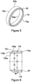
Figure 5 shows a perspective view of the deformable member shown inFigure 3 ; -
Figure 6 shows a longitudinal cross section through a fixing member for a seal system; -
Figure 7 shows a detail view of the cross section through the fixing member shown inFigure 5 ; -
Figure 8 shows a transverse cross section through the fixing member shown inFigure 6 ; -
Figure 9 shows a perspective view of the fixing member shown inFigure 6 ; -
Figure 10 shows a detail view of part of a seal system in an initial or unswollen state; and -
Figure 11 shows a detail view of part of a seal system in an operational or swollen state. -
Figure 1 shows aseal system 5 according to an embodiment of the present invention mounted on apipe 10. Theseal system 5 comprises aswellable seal 15 provided between a pair ofend members seal 15 is bonded to thepipe 10 and bothend members seal system 5 is configured such that opposite ends 25a, 25b of theswellable seal 15 are bonded tocorresponding faces end members end members pipe 10, for example, by bonding, grub screws and/or the like. - The
swellable seal 15 is in the form of a cylindrical sheath comprising inner andouter surfaces ends outer surfaces inner surface 35a defines a longitudinal through passage that is open at either end of theseal 15. Theswellable seal 15 comprises a suitable material that is selectively or preferentially swellable by specific fluids, which optionally comprise fluids found downhole, such as oil and/or water or wet gas. Theswellable seal 15 comprises, for example, a suitably swellable rubber or the like. - The
end members outer surfaces inner surface 40a defining a through passage that is open at either end of theend member end members swellable seal 15 align to form alongitudinal passage 45 through theseal system 5 that is adapted to receive or accommodate thepipe 10, such that theseal system 5 forms a sheath that can be mounted on thepipe 10. -
Figure 2 shows an alternative embodiment of a seal system 5' in situ, mounted on apipe 10. The seal system 5' ofFigure 2 is similar to that ofFigure 1 and like components are indicated with corresponding reference numerals. However, whereas theswellable seal 15 of the embodiment ofFigure 1 is bonded to both thepipe 10 and theend members swellable seal 15 of the seal system 5' ofFigure 2 is only bonded to thepipe 10 and is free to move in relation to theend members seal 15 are simply provided against, adjacent or proximate the correspondingfaces end members - In each of the above embodiments, the
end members annular end ring 50, and adeformable member 55, for example in the form of an annular elastomeric or non-elastomeric ring. Theend members deformable member 55 is provided between theend ring 50 and theswellable seal 15 such that thedeformable member 55 forms at least part of theside face end member swellable seal 15. - The
deformable member 55 is shown in more detail inFigures 3, 4 and5 . In particular, thedeformable member 55 comprises inner andouter surfaces second sides outer surfaces first side 70a of thedeformable member 55 faces theseal 15 whilst thesecond side 70b of thedeformable member 55 faces theend ring 50. Theinner surface 65a of thedeformable member 55 defines a through passage that forms part of thelongitudinal passage 45 through theseal system 5, 5' that receives thepipe 10. - The
first side 70a of thedeformable member 55 comprises a seal receiving groove in the form of anannular groove 75 that extends around thefirst side 70a of thedeformable member 55. Thegroove 75 is defined by first and secondopposed legs first leg 80a being provided radially outwardly of thesecond leg 80b (i.e. further from the passage 45). - The
groove 75 has an asymmetric cross sectional profile, with the first (i.e. the outer ward)leg 80a being longer and extending further from the body of thedeformable member 55 than thesecond leg 80b. In addition, thefirst leg 80a is provided at a shallower angle to the horizontal 85 relative to thesecond leg 80b.
In various embodiments, thefirst leg 80a may extend at an angle to the horizontal that is between 20% and 100% greater than the angle to the horizontal at which thesecond leg 80b extends. In a more specific example, thefirst leg 80a may extend at between 10° and 30° above horizontal, whilst thesecond leg 80b may extend between 20° and 40° below horizontal. In the specific non-limiting example shown inFigure 4 , thefirst leg 80a is angled at 20°above the horizontal, whilst thesecond leg 80b is angled at 30° below the horizontal. In various embodiments, thefirst leg 80a can extend between 2mm and 30mm beyond thesecond leg 80b (in an undistorted state), and preferably between 3mm and 9mm beyond. In the specific embodiment shown inFigure 4 , thefirst leg 80a extends 5.8mm (0.23inches) beyond thesecond leg 80b. The apex of the V-shapedgroove 75 is radiused. - The
second side 70b of the deformable member comprises a protrudingportion 90 that is configured to fit into a receivingrecess 95 in theend ring 50. The protrudingportion 90 comprises a v-shaped protrusion. In certain embodiments, thesurfaces deformable member 55 that form the v-shapedprotrusion 90 are subtended by an angle of between 50° and 100° and preferably between 65° and 85°. In the specific embodiment shown inFigure 4 , thesurfaces deformable member 55 that form the v-shapedprotrusion 90 are subtended by an angle of 76°. - Although various dimensions and angles of the
deformable member 55 in the undeformed state are described above, it will be appreciated that at least some of the dimensions and angles of thedeformable member 55 will be varied depending on the application, e.g. depending on the diameter ofpipe 10 upon which theseal system 5, 5' is to be mounted, the diameter of the bore or conduit into which it is to be placed, the thickness of theseal 15, the seal quality required, and the like. As such, the above dimensions and angles are merely preferable and are not intended to be exhaustive. The inner andouter surfaces deformable member 55 are angled divergently from thesecond side 70b to thefirst side 70a. In particular, thedeformable member 55 comprises a generally chevron or distorted chevron shaped cross section. - The
end ring 50 is shown in more detail inFigures 6 to 9 .Figure 6 shows a cross section through theend ring 50, whilstFigure 7 shows more detail of therecess 95.Figure 8 shows theend ring 50 in a transverse cross section andFigure 9 shows a perspective view of theend ring 50. Theend ring 50 comprises an annular member having outer andinner surfaces second sides outer surfaces first side 110a of the end ring faces toward thedeformable member 55 and thesecond side 110b of theend ring 50 forms an outer end of theseal system 5, 5'. Theinner surface 105a of theend ring 50 defines a through passage that partially forms thepassage 45 through theseal system 5, 5' in which thepipe 10 is received in order to mount theseal system 5, 5' in use. - The
end ring 50 is provided with fixing means 115 for fixing theend ring 50 on thepipe 10. In various embodiments, the fixing means 115 can comprise the provision of suitable bonding between theend ring 50 and thepipeline 10 and/or a plurality of threaded apertures for receiving set or grub screws that can be tightened so as to bear against thepipe 10 to thereby fix theseal system 5, 5' in place. - The
first side 110a of the end ring 50 (i.e. the side that faces the deformable member 55) comprises the receivingrecess 95 for receiving the protrudingportion 90 of thedeformable member 15. Therecess 95 is in the form of an annular groove that runs around thefirst side 110a of theend ring 50. Therecess 95 has a generally v-shaped cross section, as shown inFigures 6 and7 . The apex of therecess 95 is radiused. Therecess 95 is configured to open with an angle greater than the corresponding angle of theprotrusion 90 of thedeformable member 55. In this example, therecess 95 is subtended by a 90° angle. In other embodiments, therecess 95 may be subtended by an angle between 60° and 120°. - As can be seen from
Figure 10 , in an initial, unswollen state, the ends 25aof theswellable seal 15 is bevelled or comprises a protruding portion such that at least a portion of theside 25a of theseal 15 can be received within thegroove 75 of thedeformable member 55 between the opposinglegs other end 25b of the swellable seal (not shown) may also be bevelled. - In the unswollen state, the
seal member 15 is sized such that agap 120 is left between theseal member 15 and thewalls 125 of the bore, casing or conduit in which theseal system 5, 5' and pipe is inserted in order to permit easy insertion of theseal system 5, 5'. Once theseal system 5, 5' is located in the desired location, a suitable fluid that results in swelling of theswellable seal 15 is provided to theswellable seal 15 through the bore, casing or conduit. - The resulting swelling of the
swellable seal 15 closes thegap 120 between theswellable seal 15 and thewall 125 of the bore, conduit or casing. In addition, the swelling of theseal 15 applies pressure on the opposinglegs groove 75 of thedeformable member 55. This has the effect of deforming thedeformable member 55 by forcing thelegs deformable member 55 expands. Specifically, thefirst leg 80a is pushed outwardly towards and into contact with thewall 125 of the bore, casing or conduit, as can be seen inFigure 11 . As a result, thegap 120 between theend members wall 125 of the bore, casing or conduit is substantially eliminated or at least greatly reduced. In this way, the deformable member acts as a back-up or additional seal. - Furthermore, extrusion of the
swellable seal 15 past theend members deformable member 55 acts as an anti-extrusion ring. Furthermore, since thedeformable member 55 is formed from a non-metallic material, it has enough give to minimise the risk of thedeformable member 55 causing theseal system 5, 5' to stick in the hole but has enough strength to provide additional support to theswellable seal 15, biasing theseal 15 into an optimal position and providing additional or back-up sealing between thepipe 10 and the walls of the borehole, conduit or casing. In this way, improved seal quality can be obtained, which may permit the use of theseal system 5, 5' with higher pressure differentials or alternatively, may permit the use of a shorter seal system at a similar pressure range. The shape of thedeformable member 55 is such that the longerfirst leg 80a allows thegap 120 to thewall 125 of the conduit, bore or casing to be more reliably bridged. - Furthermore, the shape of the
deformable member 55 is such that the higher the pressure that is applied to thelegs second leg 80b is forced against thepipe 10 and thefirst leg 80a is forced against thewall 125 of the bore, conduit or casing. As such, the higher the pressure that is applied, the tighter the seal that is formed by thedeformable member 55, thereby permitting use at a higher operating pressure differentials. By providing therecess 95 in theend ring 50, thedeformable member 55 can be more securely located and additional support is provided to thedeformable member 55 whilst allowing thedeformable member 55 to suitably flex and deform. - While certain embodiments have been described, these embodiments have been presented by way of example only, and are not intended to limit the scope of the invention. Indeed the novel methods and systems described herein may be embodied in a variety of other forms. Furthermore, various omissions, substitutions and changes in the form of the methods and systems described herein may be made without departing from the spirit of the invention. The accompanying claims and their equivalents are intended to cover such forms and modifications as would fall within the scope of the invention.
- For example, whilst certain preferential dimensions and angles are described herein, it will be appreciated that the size and angles of the components of the
seal system 5, 5' will vary depending on the application, e.g. with the size of the pipe, the size of the bore or conduit and the like. - In addition, embodiments have been described herein wherein the seal receiving recess is advantageously in the form of a groove defined between first and second legs of the deformable member. This arrangement has advantages such as improved sealing since pressure applied to the first and second legs by the swellable member acts to force one leg into contact with the pipe and the other leg into contact with the wall or casing of the bore, conduit or hole. However, it will be appreciated that other configurations may be used. For example, the swellable member may be adhered, bonded or otherwise fixed to the pipe and the swellable member may only be provided with one leg (e.g. the upper or outer leg), such that the recess is defined by the leg of the deformable member and the surface of the pipe. In this way, the swelling of the seal acts to push the single leg radially outwardly in order to close the gap between the deformable member and the wall of casing of the bore, conduit or hole.
- Furthermore, whilst various components of the
seal system 5, 5' are described as being constructed of certain materials, it will be appreciated that the components may be fabricated from other suitable materials.
In addition, whilst theseal system 5, 5' is described as being mountable on apipe 10, it will be appreciated that the seal system is also mountable to other structures such as mandrels, cables, struts, and the like. - Whilst the above examples have been described in relation to the
seal system 5, 5' being used in a bore, it will be appreciated that the seal system may also be used in other locations, such as in casings, conduits, holes, channels and the like.
In addition, whilst theseal receiving recess 75 in specific embodiments is advantageously a groove, it will be appreciated that other shapes or forms of recess could also be used. - Furthermore, whilst the
seal 15 is described as being advantageously swellable, it will be appreciated that other seals, such as expandable seals, that are expandable or movable in order to deform the deformable member could be used. Examples of such alternative seals may include inflatable or pressurizable seals, seals that comprise a compressed resilient material that are expandable when released and the like.
Claims (17)
- A downhole seal system (5, 5') comprising:at least one expandable seal (15);at least one deformable member (55);a fixing member (50) fixed relative to the deformable member (55) to securely locate the deformable member (55) in the seal system;the deformable member (55) comprising or at least partially defining a seal receiving groove (75) and at least part of the expandable seal (15) being received or receivable within the seal receiving groove (75) such that the expandable seal (15) is expandable so as to deform the deformable member (55), the deformable member (55) being securely located by the fixing member (50), and thereby increase an outer diameter or extent of the deformable member (55);wherein the groove (75) is at least partially defined by at least two opposing legs (80a, 80b), the opposing legs (80a, 80b) comprising an upper or outer leg (80a) and a lower or inner leg (80b), wherein the upper or outer leg (80a) is provided radially outwardly of the lower or inner leg (80b).
- The seal system (5, 5') of claim 1, wherein the expandable seal (15) is or comprises a swellable seal.
- The seal system (5, 5') according to any preceding claim, wherein the seal system (5') comprises a pair of end members (20a, 20b), one or more of the deformable members (55) is comprised within each of the end members (20a, 20b) and at least part of the at least one expandable seal (15) is provided between the end members (20a, 20b).
- The seal system (5, 5') according to any preceding claim, wherein the expandable seal (15) is adapted for sealing against the walls (125) or casing of a hole, conduit or borehole in which the seal system (5') is located when the seal (15) is swollen.
- The seal system (5, 5') according to any preceding claim, wherein the deformable member (55) comprises a non-metallic material.
- The seal system (5, 5') according to any preceding claim, wherein one of the legs (80a, 80b) extends further from the body of the deformable member (55) than the other leg and/or one of the legs (80a, 80b).
- The seal system (5, 5') according to any preceding claim, wherein the deformable member (55) is provided between the fixing member (50) and the expandable seal (15).
- The seal system (5, 5') according to any preceding claim, wherein the fixing member (50) comprises a recess (95) for at least partially receiving the deformable member (55).
- The seal system (5, 5') according to claim 8, wherein a surface (100a, 100b) of the deformable member (55) that faces the fixing member (50) comprises a protruding profile (90) shaped to fit into the recess (95) of the fixing member (50).
- The seal system (5, 5') according to any preceding claim, wherein the deformable member (55) has a cross section in the form of a chevron or a distorted or asymmetric chevron.
- The seal system (5, 5') according to any preceding claim, wherein at least part of at least one end (25a, 25b) of the expandable seal (15) is outwardly protruding or bevelled so as to extend at least partially into the seal receiving groove (75) of the deformable member (55).
- The seal system (5, 5') according to any preceding claim, wherein the seal system (5') is configured such that as the expandable seal (15) expands, the expandable seal (15) applies a force to the opposing legs (80a, 80b) of the groove (75) of the deformable member (55) so as to deform the deformable member (55) by pushing the opposing legs (80a, 80b) apart and/or push the upper or outer leg (80a) of the groove (75) of the deformable member (55) radially outwardly.
- A deformable member (55) for use with the seal system (5, 5') of any of claims 1 to 12, the deformable member (55) comprising or at least partially defining a seal receiving groove (75) wherein the groove (75) is at least partially defined by at least two opposing legs (80a, 80b) comprising an upper or outer leg (80a) and a lower or inner leg (80b), wherein the upper or outer leg (80a) is provided radially outwardly of the lower or inner leg (80b).
- A fixing member for use in the seal system according to any of claims 1 to 12, wherein the fixing member is rigid and fixed or fixable to a pipe or other structure upon which the seal device is mounted, the fixing member comprising a recess for at least partially receiving a deformable member.
- A method for producing the seal system according to any of claims 1 to 12, the method comprising providing a deformable member according to claim 13 between a fixing member according to claim 14 and an expandable seal.
- The method according to claim 15, comprising providing a part of the expandable seal within a seal receiving groove in the deformable member.
- A method for using a seal system of claims 1 to 12, the method comprising:mounting the seal system to a pipe or other structure, such that at least a portion of the pipe or other structure is received within a passageway or annulus of the seal system;providing fluid to the seal(s) so as to swell the seal to deform the deformable member so as to increase an outer diameter or extent of the deformable member.
Applications Claiming Priority (2)
| Application Number | Priority Date | Filing Date | Title |
|---|---|---|---|
| GB1308067.6A GB2513851A (en) | 2013-05-03 | 2013-05-03 | A packer and associated methods, seal ring and fixing ring |
| PCT/GB2014/051342 WO2014177865A2 (en) | 2013-05-03 | 2014-04-30 | A packer and associated methods, seal ring and fixing ring |
Publications (2)
| Publication Number | Publication Date |
|---|---|
| EP2992174A2 EP2992174A2 (en) | 2016-03-09 |
| EP2992174B1 true EP2992174B1 (en) | 2018-09-19 |
Family
ID=48627304
Family Applications (1)
| Application Number | Title | Priority Date | Filing Date |
|---|---|---|---|
| EP14721941.4A Active EP2992174B1 (en) | 2013-05-03 | 2014-04-30 | A packer and associated methods, seal ring and fixing ring |
Country Status (9)
| Country | Link |
|---|---|
| US (1) | US10370929B2 (en) |
| EP (1) | EP2992174B1 (en) |
| CN (1) | CN105452596A (en) |
| AU (1) | AU2014261214B2 (en) |
| CA (1) | CA2911359C (en) |
| DK (1) | DK2992174T3 (en) |
| GB (1) | GB2513851A (en) |
| RU (1) | RU2015151588A (en) |
| WO (1) | WO2014177865A2 (en) |
Families Citing this family (3)
| Publication number | Priority date | Publication date | Assignee | Title |
|---|---|---|---|---|
| US10344585B2 (en) * | 2015-03-26 | 2019-07-09 | Chevron U.S.A. Inc. | Methods, apparatus, and systems for steam flow profiling |
| CN105863552B (en) * | 2016-05-20 | 2019-05-03 | 天鼎联创密封技术(北京)有限公司 | The harder packing element in upper end, packer and bridge plug |
| CN118882217B (en) * | 2024-08-13 | 2025-02-14 | 文和王集团吉林省文吉能源科技有限公司 | Ground source heat pump buried pipe structure |
Citations (1)
| Publication number | Priority date | Publication date | Assignee | Title |
|---|---|---|---|---|
| US20060186601A1 (en) * | 2005-02-18 | 2006-08-24 | Jean-Marc Lopez | Fluid seals |
Family Cites Families (24)
| Publication number | Priority date | Publication date | Assignee | Title |
|---|---|---|---|---|
| SU1758207A1 (en) | 1990-02-27 | 1992-08-30 | Казахский Государственный Научно-Исследовательский И Проектный Институт Нефтяной Промышленности | Device for formation isolation |
| CN2400569Y (en) * | 1999-10-30 | 2000-10-11 | 中原石油勘探局采油五厂 | New well-flushing packer |
| WO2002079606A1 (en) * | 2001-03-29 | 2002-10-10 | Greene, Tweed Of Deleware, Inc. | Method for producing sealing and anti-extrusion components for use in downhole tools and components produced thereby |
| US20030209861A1 (en) * | 2002-05-10 | 2003-11-13 | Cooper Cameron Corporation | Metal end cap seal with pressure trap |
| US20030209862A1 (en) * | 2002-05-10 | 2003-11-13 | Cooper Cameron Corporation | Metal end cap seal with annular protrusions |
| US20030222410A1 (en) * | 2002-05-30 | 2003-12-04 | Williams Ronald D. | High pressure and temperature seal for downhole use |
| CN1280443C (en) * | 2004-07-01 | 2006-10-18 | 陈玉如 | Expanding metal material and bulged tube device for petroleum oil well |
| RU43582U1 (en) | 2004-09-27 | 2005-01-27 | Закрытое акционерное общество Научно-производственное предприятие "ОСКОН" | PACKER |
| US7392851B2 (en) * | 2004-11-04 | 2008-07-01 | Schlumberger Technology Corporation | Inflatable packer assembly |
| NO327157B1 (en) | 2005-05-09 | 2009-05-04 | Easy Well Solutions As | Anchoring device for an annulus gasket having a first second end region and mounted on a tubular element |
| US7708080B2 (en) * | 2005-06-23 | 2010-05-04 | Schlumberger Technology Corporation | Packer |
| US7431098B2 (en) * | 2006-01-05 | 2008-10-07 | Schlumberger Technology Corporation | System and method for isolating a wellbore region |
| WO2008154392A1 (en) * | 2007-06-06 | 2008-12-18 | Baker Hughes Incorporated | Swellable packer with back-up systems |
| WO2009073538A1 (en) * | 2007-11-30 | 2009-06-11 | Baker Hughes Incorporated | Downhole tool with capillary biasing system |
| US7938176B2 (en) * | 2008-08-15 | 2011-05-10 | Schlumberger Technology Corporation | Anti-extrusion device for swell rubber packer |
| GB2469870A (en) * | 2009-05-01 | 2010-11-03 | Swelltec Ltd | Support assembly for a downhole tool |
| US7963321B2 (en) * | 2009-05-15 | 2011-06-21 | Tam International, Inc. | Swellable downhole packer |
| CN201474655U (en) * | 2009-08-15 | 2010-05-19 | 西部钻探克拉玛依钻井工艺研究院 | Expanded packer used in oil supply |
| GB0914416D0 (en) * | 2009-08-18 | 2009-09-30 | Rubberatkins Ltd | Pressure control device |
| CN102337855A (en) * | 2010-07-14 | 2012-02-01 | 中国石油天然气股份有限公司 | A pre-packed self-expandable packer for well completion |
| US8997854B2 (en) * | 2010-07-23 | 2015-04-07 | Weatherford Technology Holdings, Llc | Swellable packer anchors |
| CN201908615U (en) * | 2010-12-16 | 2011-07-27 | 中国石油天然气股份有限公司 | A Layered Steam Injection Packer |
| RU108095U1 (en) | 2011-05-26 | 2011-09-10 | Алексей Викторович Власов | PACKER |
| CA2842378C (en) * | 2011-08-22 | 2017-07-04 | National Boss Hog Energy Services Llc | Downhole tool and method of use |
-
2013
- 2013-05-03 GB GB1308067.6A patent/GB2513851A/en not_active Withdrawn
-
2014
- 2014-04-30 DK DK14721941.4T patent/DK2992174T3/en active
- 2014-04-30 CA CA2911359A patent/CA2911359C/en active Active
- 2014-04-30 US US14/888,790 patent/US10370929B2/en active Active
- 2014-04-30 AU AU2014261214A patent/AU2014261214B2/en active Active
- 2014-04-30 RU RU2015151588A patent/RU2015151588A/en not_active Application Discontinuation
- 2014-04-30 CN CN201480031530.0A patent/CN105452596A/en active Pending
- 2014-04-30 EP EP14721941.4A patent/EP2992174B1/en active Active
- 2014-04-30 WO PCT/GB2014/051342 patent/WO2014177865A2/en not_active Ceased
Patent Citations (1)
| Publication number | Priority date | Publication date | Assignee | Title |
|---|---|---|---|---|
| US20060186601A1 (en) * | 2005-02-18 | 2006-08-24 | Jean-Marc Lopez | Fluid seals |
Also Published As
| Publication number | Publication date |
|---|---|
| CA2911359C (en) | 2021-02-23 |
| GB201308067D0 (en) | 2013-06-12 |
| US20160084033A1 (en) | 2016-03-24 |
| RU2015151588A3 (en) | 2018-03-29 |
| RU2015151588A (en) | 2017-06-08 |
| AU2014261214A1 (en) | 2015-12-10 |
| US10370929B2 (en) | 2019-08-06 |
| CA2911359A1 (en) | 2014-11-06 |
| WO2014177865A2 (en) | 2014-11-06 |
| DK2992174T3 (en) | 2019-01-21 |
| CN105452596A (en) | 2016-03-30 |
| EP2992174A2 (en) | 2016-03-09 |
| GB2513851A (en) | 2014-11-12 |
| AU2014261214B2 (en) | 2018-02-08 |
| WO2014177865A3 (en) | 2015-04-09 |
Similar Documents
| Publication | Publication Date | Title |
|---|---|---|
| US9376882B2 (en) | Self-energizing annular seal | |
| US9217308B2 (en) | Active external casing packer (ECP) for frac operations in oil and gas wells | |
| AU2014253098B2 (en) | A downhole expandable tubular | |
| RU2477365C1 (en) | Anchors of swelling packers | |
| EP2246522B1 (en) | Improvements to swellable apparatus | |
| CA2710329A1 (en) | Securing a composite bridge plug | |
| GB2346632A (en) | A deformable downhole sealing device | |
| EP2986813B1 (en) | Anchor ring assembly | |
| NO20201115A1 (en) | Metal-to-metal annulus wellhead style seal with pressure energized from above and below | |
| CA2911359C (en) | A packer and associated methods, seal ring and fixing ring | |
| US10316610B2 (en) | Downhole packer and associated methods | |
| GB2383361A (en) | A packer/seal produced by plastically deforming a tubular | |
| US20150267497A1 (en) | Sealing apparatus and method | |
| US20150211323A1 (en) | Sealing apparatus and method | |
| CN112601875A (en) | Anti-extrusion assembly and sealing system including the same | |
| US20150191989A1 (en) | Sealing apparatus and method |
Legal Events
| Date | Code | Title | Description |
|---|---|---|---|
| PUAI | Public reference made under article 153(3) epc to a published international application that has entered the european phase |
Free format text: ORIGINAL CODE: 0009012 |
|
| 17P | Request for examination filed |
Effective date: 20151030 |
|
| AK | Designated contracting states |
Kind code of ref document: A2 Designated state(s): AL AT BE BG CH CY CZ DE DK EE ES FI FR GB GR HR HU IE IS IT LI LT LU LV MC MK MT NL NO PL PT RO RS SE SI SK SM TR |
|
| AX | Request for extension of the european patent |
Extension state: BA ME |
|
| DAX | Request for extension of the european patent (deleted) | ||
| STAA | Information on the status of an ep patent application or granted ep patent |
Free format text: STATUS: EXAMINATION IS IN PROGRESS |
|
| 17Q | First examination report despatched |
Effective date: 20170210 |
|
| REG | Reference to a national code |
Ref country code: DE Ref legal event code: R079 Ref document number: 602014032511 Country of ref document: DE Free format text: PREVIOUS MAIN CLASS: E21B0033120000 Ipc: E21B0023060000 |
|
| RIC1 | Information provided on ipc code assigned before grant |
Ipc: E21B 23/06 20060101AFI20180129BHEP Ipc: E21B 33/12 20060101ALI20180129BHEP |
|
| GRAP | Despatch of communication of intention to grant a patent |
Free format text: ORIGINAL CODE: EPIDOSNIGR1 |
|
| STAA | Information on the status of an ep patent application or granted ep patent |
Free format text: STATUS: GRANT OF PATENT IS INTENDED |
|
| INTG | Intention to grant announced |
Effective date: 20180403 |
|
| GRAS | Grant fee paid |
Free format text: ORIGINAL CODE: EPIDOSNIGR3 |
|
| GRAA | (expected) grant |
Free format text: ORIGINAL CODE: 0009210 |
|
| STAA | Information on the status of an ep patent application or granted ep patent |
Free format text: STATUS: THE PATENT HAS BEEN GRANTED |
|
| AK | Designated contracting states |
Kind code of ref document: B1 Designated state(s): AL AT BE BG CH CY CZ DE DK EE ES FI FR GB GR HR HU IE IS IT LI LT LU LV MC MK MT NL NO PL PT RO RS SE SI SK SM TR |
|
| REG | Reference to a national code |
Ref country code: GB Ref legal event code: FG4D |
|
| REG | Reference to a national code |
Ref country code: CH Ref legal event code: EP |
|
| REG | Reference to a national code |
Ref country code: AT Ref legal event code: REF Ref document number: 1043466 Country of ref document: AT Kind code of ref document: T Effective date: 20181015 |
|
| REG | Reference to a national code |
Ref country code: IE Ref legal event code: FG4D |
|
| REG | Reference to a national code |
Ref country code: DE Ref legal event code: R096 Ref document number: 602014032511 Country of ref document: DE |
|
| REG | Reference to a national code |
Ref country code: NL Ref legal event code: FP |
|
| REG | Reference to a national code |
Ref country code: DK Ref legal event code: T3 Effective date: 20190108 |
|
| PG25 | Lapsed in a contracting state [announced via postgrant information from national office to epo] |
Ref country code: FI Free format text: LAPSE BECAUSE OF FAILURE TO SUBMIT A TRANSLATION OF THE DESCRIPTION OR TO PAY THE FEE WITHIN THE PRESCRIBED TIME-LIMIT Effective date: 20180919 Ref country code: SE Free format text: LAPSE BECAUSE OF FAILURE TO SUBMIT A TRANSLATION OF THE DESCRIPTION OR TO PAY THE FEE WITHIN THE PRESCRIBED TIME-LIMIT Effective date: 20180919 Ref country code: RS Free format text: LAPSE BECAUSE OF FAILURE TO SUBMIT A TRANSLATION OF THE DESCRIPTION OR TO PAY THE FEE WITHIN THE PRESCRIBED TIME-LIMIT Effective date: 20180919 Ref country code: LT Free format text: LAPSE BECAUSE OF FAILURE TO SUBMIT A TRANSLATION OF THE DESCRIPTION OR TO PAY THE FEE WITHIN THE PRESCRIBED TIME-LIMIT Effective date: 20180919 Ref country code: GR Free format text: LAPSE BECAUSE OF FAILURE TO SUBMIT A TRANSLATION OF THE DESCRIPTION OR TO PAY THE FEE WITHIN THE PRESCRIBED TIME-LIMIT Effective date: 20181220 Ref country code: BG Free format text: LAPSE BECAUSE OF FAILURE TO SUBMIT A TRANSLATION OF THE DESCRIPTION OR TO PAY THE FEE WITHIN THE PRESCRIBED TIME-LIMIT Effective date: 20181219 |
|
| REG | Reference to a national code |
Ref country code: LT Ref legal event code: MG4D Ref country code: NO Ref legal event code: T2 Effective date: 20180919 |
|
| PG25 | Lapsed in a contracting state [announced via postgrant information from national office to epo] |
Ref country code: AL Free format text: LAPSE BECAUSE OF FAILURE TO SUBMIT A TRANSLATION OF THE DESCRIPTION OR TO PAY THE FEE WITHIN THE PRESCRIBED TIME-LIMIT Effective date: 20180919 Ref country code: HR Free format text: LAPSE BECAUSE OF FAILURE TO SUBMIT A TRANSLATION OF THE DESCRIPTION OR TO PAY THE FEE WITHIN THE PRESCRIBED TIME-LIMIT Effective date: 20180919 Ref country code: LV Free format text: LAPSE BECAUSE OF FAILURE TO SUBMIT A TRANSLATION OF THE DESCRIPTION OR TO PAY THE FEE WITHIN THE PRESCRIBED TIME-LIMIT Effective date: 20180919 |
|
| REG | Reference to a national code |
Ref country code: AT Ref legal event code: MK05 Ref document number: 1043466 Country of ref document: AT Kind code of ref document: T Effective date: 20180919 |
|
| PG25 | Lapsed in a contracting state [announced via postgrant information from national office to epo] |
Ref country code: AT Free format text: LAPSE BECAUSE OF FAILURE TO SUBMIT A TRANSLATION OF THE DESCRIPTION OR TO PAY THE FEE WITHIN THE PRESCRIBED TIME-LIMIT Effective date: 20180919 Ref country code: IS Free format text: LAPSE BECAUSE OF FAILURE TO SUBMIT A TRANSLATION OF THE DESCRIPTION OR TO PAY THE FEE WITHIN THE PRESCRIBED TIME-LIMIT Effective date: 20190119 Ref country code: PL Free format text: LAPSE BECAUSE OF FAILURE TO SUBMIT A TRANSLATION OF THE DESCRIPTION OR TO PAY THE FEE WITHIN THE PRESCRIBED TIME-LIMIT Effective date: 20180919 Ref country code: EE Free format text: LAPSE BECAUSE OF FAILURE TO SUBMIT A TRANSLATION OF THE DESCRIPTION OR TO PAY THE FEE WITHIN THE PRESCRIBED TIME-LIMIT Effective date: 20180919 Ref country code: ES Free format text: LAPSE BECAUSE OF FAILURE TO SUBMIT A TRANSLATION OF THE DESCRIPTION OR TO PAY THE FEE WITHIN THE PRESCRIBED TIME-LIMIT Effective date: 20180919 Ref country code: CZ Free format text: LAPSE BECAUSE OF FAILURE TO SUBMIT A TRANSLATION OF THE DESCRIPTION OR TO PAY THE FEE WITHIN THE PRESCRIBED TIME-LIMIT Effective date: 20180919 Ref country code: RO Free format text: LAPSE BECAUSE OF FAILURE TO SUBMIT A TRANSLATION OF THE DESCRIPTION OR TO PAY THE FEE WITHIN THE PRESCRIBED TIME-LIMIT Effective date: 20180919 Ref country code: IT Free format text: LAPSE BECAUSE OF FAILURE TO SUBMIT A TRANSLATION OF THE DESCRIPTION OR TO PAY THE FEE WITHIN THE PRESCRIBED TIME-LIMIT Effective date: 20180919 |
|
| PG25 | Lapsed in a contracting state [announced via postgrant information from national office to epo] |
Ref country code: PT Free format text: LAPSE BECAUSE OF FAILURE TO SUBMIT A TRANSLATION OF THE DESCRIPTION OR TO PAY THE FEE WITHIN THE PRESCRIBED TIME-LIMIT Effective date: 20190119 Ref country code: SM Free format text: LAPSE BECAUSE OF FAILURE TO SUBMIT A TRANSLATION OF THE DESCRIPTION OR TO PAY THE FEE WITHIN THE PRESCRIBED TIME-LIMIT Effective date: 20180919 Ref country code: SK Free format text: LAPSE BECAUSE OF FAILURE TO SUBMIT A TRANSLATION OF THE DESCRIPTION OR TO PAY THE FEE WITHIN THE PRESCRIBED TIME-LIMIT Effective date: 20180919 |
|
| REG | Reference to a national code |
Ref country code: DE Ref legal event code: R097 Ref document number: 602014032511 Country of ref document: DE |
|
| PLBE | No opposition filed within time limit |
Free format text: ORIGINAL CODE: 0009261 |
|
| STAA | Information on the status of an ep patent application or granted ep patent |
Free format text: STATUS: NO OPPOSITION FILED WITHIN TIME LIMIT |
|
| 26N | No opposition filed |
Effective date: 20190620 |
|
| PG25 | Lapsed in a contracting state [announced via postgrant information from national office to epo] |
Ref country code: SI Free format text: LAPSE BECAUSE OF FAILURE TO SUBMIT A TRANSLATION OF THE DESCRIPTION OR TO PAY THE FEE WITHIN THE PRESCRIBED TIME-LIMIT Effective date: 20180919 |
|
| REG | Reference to a national code |
Ref country code: DE Ref legal event code: R119 Ref document number: 602014032511 Country of ref document: DE |
|
| REG | Reference to a national code |
Ref country code: CH Ref legal event code: PL |
|
| REG | Reference to a national code |
Ref country code: BE Ref legal event code: MM Effective date: 20190430 |
|
| PG25 | Lapsed in a contracting state [announced via postgrant information from national office to epo] |
Ref country code: MC Free format text: LAPSE BECAUSE OF FAILURE TO SUBMIT A TRANSLATION OF THE DESCRIPTION OR TO PAY THE FEE WITHIN THE PRESCRIBED TIME-LIMIT Effective date: 20180919 Ref country code: LU Free format text: LAPSE BECAUSE OF NON-PAYMENT OF DUE FEES Effective date: 20190430 |
|
| PG25 | Lapsed in a contracting state [announced via postgrant information from national office to epo] |
Ref country code: CH Free format text: LAPSE BECAUSE OF NON-PAYMENT OF DUE FEES Effective date: 20190430 Ref country code: DE Free format text: LAPSE BECAUSE OF NON-PAYMENT OF DUE FEES Effective date: 20191101 Ref country code: LI Free format text: LAPSE BECAUSE OF NON-PAYMENT OF DUE FEES Effective date: 20190430 |
|
| PG25 | Lapsed in a contracting state [announced via postgrant information from national office to epo] |
Ref country code: BE Free format text: LAPSE BECAUSE OF NON-PAYMENT OF DUE FEES Effective date: 20190430 Ref country code: FR Free format text: LAPSE BECAUSE OF NON-PAYMENT OF DUE FEES Effective date: 20190430 |
|
| PG25 | Lapsed in a contracting state [announced via postgrant information from national office to epo] |
Ref country code: TR Free format text: LAPSE BECAUSE OF FAILURE TO SUBMIT A TRANSLATION OF THE DESCRIPTION OR TO PAY THE FEE WITHIN THE PRESCRIBED TIME-LIMIT Effective date: 20180919 |
|
| PG25 | Lapsed in a contracting state [announced via postgrant information from national office to epo] |
Ref country code: IE Free format text: LAPSE BECAUSE OF NON-PAYMENT OF DUE FEES Effective date: 20190430 |
|
| PG25 | Lapsed in a contracting state [announced via postgrant information from national office to epo] |
Ref country code: CY Free format text: LAPSE BECAUSE OF FAILURE TO SUBMIT A TRANSLATION OF THE DESCRIPTION OR TO PAY THE FEE WITHIN THE PRESCRIBED TIME-LIMIT Effective date: 20180919 |
|
| PG25 | Lapsed in a contracting state [announced via postgrant information from national office to epo] |
Ref country code: HU Free format text: LAPSE BECAUSE OF FAILURE TO SUBMIT A TRANSLATION OF THE DESCRIPTION OR TO PAY THE FEE WITHIN THE PRESCRIBED TIME-LIMIT; INVALID AB INITIO Effective date: 20140430 Ref country code: MT Free format text: LAPSE BECAUSE OF FAILURE TO SUBMIT A TRANSLATION OF THE DESCRIPTION OR TO PAY THE FEE WITHIN THE PRESCRIBED TIME-LIMIT Effective date: 20180919 |
|
| PG25 | Lapsed in a contracting state [announced via postgrant information from national office to epo] |
Ref country code: MK Free format text: LAPSE BECAUSE OF FAILURE TO SUBMIT A TRANSLATION OF THE DESCRIPTION OR TO PAY THE FEE WITHIN THE PRESCRIBED TIME-LIMIT Effective date: 20180919 |
|
| PGFP | Annual fee paid to national office [announced via postgrant information from national office to epo] |
Ref country code: NL Payment date: 20250424 Year of fee payment: 12 |
|
| PGFP | Annual fee paid to national office [announced via postgrant information from national office to epo] |
Ref country code: DK Payment date: 20250424 Year of fee payment: 12 Ref country code: GB Payment date: 20250422 Year of fee payment: 12 |
|
| PGFP | Annual fee paid to national office [announced via postgrant information from national office to epo] |
Ref country code: NO Payment date: 20250422 Year of fee payment: 12 |