EP2991592B2 - Coordinated control for an arm prosthesis - Google Patents
Coordinated control for an arm prosthesis Download PDFInfo
- Publication number
- EP2991592B2 EP2991592B2 EP14732473.5A EP14732473A EP2991592B2 EP 2991592 B2 EP2991592 B2 EP 2991592B2 EP 14732473 A EP14732473 A EP 14732473A EP 2991592 B2 EP2991592 B2 EP 2991592B2
- Authority
- EP
- European Patent Office
- Prior art keywords
- powered
- joint
- elbow joint
- control signals
- arm
- Prior art date
- Legal status (The legal status is an assumption and is not a legal conclusion. Google has not performed a legal analysis and makes no representation as to the accuracy of the status listed.)
- Active
Links
- 210000002310 elbow joint Anatomy 0.000 claims description 113
- 238000000034 method Methods 0.000 claims description 46
- 210000000245 forearm Anatomy 0.000 claims description 17
- 210000003857 wrist joint Anatomy 0.000 claims description 15
- 238000005259 measurement Methods 0.000 claims description 13
- 239000013598 vector Substances 0.000 claims description 10
- 230000002459 sustained effect Effects 0.000 claims description 5
- 230000008859 change Effects 0.000 claims description 2
- 238000004590 computer program Methods 0.000 claims 2
- 210000000323 shoulder joint Anatomy 0.000 description 41
- 210000001503 joint Anatomy 0.000 description 24
- 230000003183 myoelectrical effect Effects 0.000 description 17
- 238000005516 engineering process Methods 0.000 description 16
- 230000015654 memory Effects 0.000 description 15
- 210000003414 extremity Anatomy 0.000 description 14
- 230000006870 function Effects 0.000 description 12
- 210000003205 muscle Anatomy 0.000 description 12
- 238000013459 approach Methods 0.000 description 11
- 210000000707 wrist Anatomy 0.000 description 7
- 230000009471 action Effects 0.000 description 6
- 238000004891 communication Methods 0.000 description 4
- 230000000694 effects Effects 0.000 description 4
- 230000005484 gravity Effects 0.000 description 4
- 238000012545 processing Methods 0.000 description 4
- 239000000556 agonist Substances 0.000 description 2
- 239000005557 antagonist Substances 0.000 description 2
- 230000008602 contraction Effects 0.000 description 2
- 230000008878 coupling Effects 0.000 description 2
- 238000010168 coupling process Methods 0.000 description 2
- 238000005859 coupling reaction Methods 0.000 description 2
- 239000011159 matrix material Substances 0.000 description 2
- 230000007246 mechanism Effects 0.000 description 2
- 230000004118 muscle contraction Effects 0.000 description 2
- 239000007787 solid Substances 0.000 description 2
- 230000001133 acceleration Effects 0.000 description 1
- 230000004075 alteration Effects 0.000 description 1
- 238000002266 amputation Methods 0.000 description 1
- 230000008901 benefit Effects 0.000 description 1
- 230000002457 bidirectional effect Effects 0.000 description 1
- 230000000295 complement effect Effects 0.000 description 1
- 230000007423 decrease Effects 0.000 description 1
- 230000001934 delay Effects 0.000 description 1
- 238000013461 design Methods 0.000 description 1
- 238000001514 detection method Methods 0.000 description 1
- 238000006073 displacement reaction Methods 0.000 description 1
- 210000002758 humerus Anatomy 0.000 description 1
- 230000010354 integration Effects 0.000 description 1
- 230000003993 interaction Effects 0.000 description 1
- 238000012986 modification Methods 0.000 description 1
- 230000004048 modification Effects 0.000 description 1
- 230000003287 optical effect Effects 0.000 description 1
- 230000002093 peripheral effect Effects 0.000 description 1
- 230000008569 process Effects 0.000 description 1
- 230000002035 prolonged effect Effects 0.000 description 1
- 230000009023 proprioceptive sensation Effects 0.000 description 1
- 230000004044 response Effects 0.000 description 1
Images
Classifications
-
- A—HUMAN NECESSITIES
- A61—MEDICAL OR VETERINARY SCIENCE; HYGIENE
- A61F—FILTERS IMPLANTABLE INTO BLOOD VESSELS; PROSTHESES; DEVICES PROVIDING PATENCY TO, OR PREVENTING COLLAPSING OF, TUBULAR STRUCTURES OF THE BODY, e.g. STENTS; ORTHOPAEDIC, NURSING OR CONTRACEPTIVE DEVICES; FOMENTATION; TREATMENT OR PROTECTION OF EYES OR EARS; BANDAGES, DRESSINGS OR ABSORBENT PADS; FIRST-AID KITS
- A61F2/00—Filters implantable into blood vessels; Prostheses, i.e. artificial substitutes or replacements for parts of the body; Appliances for connecting them with the body; Devices providing patency to, or preventing collapsing of, tubular structures of the body, e.g. stents
- A61F2/50—Prostheses not implantable in the body
- A61F2/68—Operating or control means
- A61F2/70—Operating or control means electrical
- A61F2/72—Bioelectric control, e.g. myoelectric
-
- A—HUMAN NECESSITIES
- A61—MEDICAL OR VETERINARY SCIENCE; HYGIENE
- A61F—FILTERS IMPLANTABLE INTO BLOOD VESSELS; PROSTHESES; DEVICES PROVIDING PATENCY TO, OR PREVENTING COLLAPSING OF, TUBULAR STRUCTURES OF THE BODY, e.g. STENTS; ORTHOPAEDIC, NURSING OR CONTRACEPTIVE DEVICES; FOMENTATION; TREATMENT OR PROTECTION OF EYES OR EARS; BANDAGES, DRESSINGS OR ABSORBENT PADS; FIRST-AID KITS
- A61F2/00—Filters implantable into blood vessels; Prostheses, i.e. artificial substitutes or replacements for parts of the body; Appliances for connecting them with the body; Devices providing patency to, or preventing collapsing of, tubular structures of the body, e.g. stents
- A61F2/50—Prostheses not implantable in the body
- A61F2/54—Artificial arms or hands or parts thereof
- A61F2/58—Elbows; Wrists ; Other joints; Hands
- A61F2/582—Elbow joints
-
- A—HUMAN NECESSITIES
- A61—MEDICAL OR VETERINARY SCIENCE; HYGIENE
- A61F—FILTERS IMPLANTABLE INTO BLOOD VESSELS; PROSTHESES; DEVICES PROVIDING PATENCY TO, OR PREVENTING COLLAPSING OF, TUBULAR STRUCTURES OF THE BODY, e.g. STENTS; ORTHOPAEDIC, NURSING OR CONTRACEPTIVE DEVICES; FOMENTATION; TREATMENT OR PROTECTION OF EYES OR EARS; BANDAGES, DRESSINGS OR ABSORBENT PADS; FIRST-AID KITS
- A61F2/00—Filters implantable into blood vessels; Prostheses, i.e. artificial substitutes or replacements for parts of the body; Appliances for connecting them with the body; Devices providing patency to, or preventing collapsing of, tubular structures of the body, e.g. stents
- A61F2/50—Prostheses not implantable in the body
- A61F2/54—Artificial arms or hands or parts thereof
- A61F2/58—Elbows; Wrists ; Other joints; Hands
- A61F2/583—Hands; Wrist joints
- A61F2/585—Wrist joints
-
- G—PHYSICS
- G05—CONTROLLING; REGULATING
- G05B—CONTROL OR REGULATING SYSTEMS IN GENERAL; FUNCTIONAL ELEMENTS OF SUCH SYSTEMS; MONITORING OR TESTING ARRANGEMENTS FOR SUCH SYSTEMS OR ELEMENTS
- G05B15/00—Systems controlled by a computer
- G05B15/02—Systems controlled by a computer electric
-
- A—HUMAN NECESSITIES
- A61—MEDICAL OR VETERINARY SCIENCE; HYGIENE
- A61F—FILTERS IMPLANTABLE INTO BLOOD VESSELS; PROSTHESES; DEVICES PROVIDING PATENCY TO, OR PREVENTING COLLAPSING OF, TUBULAR STRUCTURES OF THE BODY, e.g. STENTS; ORTHOPAEDIC, NURSING OR CONTRACEPTIVE DEVICES; FOMENTATION; TREATMENT OR PROTECTION OF EYES OR EARS; BANDAGES, DRESSINGS OR ABSORBENT PADS; FIRST-AID KITS
- A61F2/00—Filters implantable into blood vessels; Prostheses, i.e. artificial substitutes or replacements for parts of the body; Appliances for connecting them with the body; Devices providing patency to, or preventing collapsing of, tubular structures of the body, e.g. stents
- A61F2/50—Prostheses not implantable in the body
- A61F2/54—Artificial arms or hands or parts thereof
- A61F2002/543—Lower arms or forearms
-
- A—HUMAN NECESSITIES
- A61—MEDICAL OR VETERINARY SCIENCE; HYGIENE
- A61F—FILTERS IMPLANTABLE INTO BLOOD VESSELS; PROSTHESES; DEVICES PROVIDING PATENCY TO, OR PREVENTING COLLAPSING OF, TUBULAR STRUCTURES OF THE BODY, e.g. STENTS; ORTHOPAEDIC, NURSING OR CONTRACEPTIVE DEVICES; FOMENTATION; TREATMENT OR PROTECTION OF EYES OR EARS; BANDAGES, DRESSINGS OR ABSORBENT PADS; FIRST-AID KITS
- A61F2/00—Filters implantable into blood vessels; Prostheses, i.e. artificial substitutes or replacements for parts of the body; Appliances for connecting them with the body; Devices providing patency to, or preventing collapsing of, tubular structures of the body, e.g. stents
- A61F2/50—Prostheses not implantable in the body
- A61F2/54—Artificial arms or hands or parts thereof
- A61F2002/546—Upper arms
-
- A—HUMAN NECESSITIES
- A61—MEDICAL OR VETERINARY SCIENCE; HYGIENE
- A61F—FILTERS IMPLANTABLE INTO BLOOD VESSELS; PROSTHESES; DEVICES PROVIDING PATENCY TO, OR PREVENTING COLLAPSING OF, TUBULAR STRUCTURES OF THE BODY, e.g. STENTS; ORTHOPAEDIC, NURSING OR CONTRACEPTIVE DEVICES; FOMENTATION; TREATMENT OR PROTECTION OF EYES OR EARS; BANDAGES, DRESSINGS OR ABSORBENT PADS; FIRST-AID KITS
- A61F2/00—Filters implantable into blood vessels; Prostheses, i.e. artificial substitutes or replacements for parts of the body; Appliances for connecting them with the body; Devices providing patency to, or preventing collapsing of, tubular structures of the body, e.g. stents
- A61F2/50—Prostheses not implantable in the body
- A61F2/68—Operating or control means
- A61F2/70—Operating or control means electrical
- A61F2002/704—Operating or control means electrical computer-controlled, e.g. robotic control
-
- A—HUMAN NECESSITIES
- A61—MEDICAL OR VETERINARY SCIENCE; HYGIENE
- A61F—FILTERS IMPLANTABLE INTO BLOOD VESSELS; PROSTHESES; DEVICES PROVIDING PATENCY TO, OR PREVENTING COLLAPSING OF, TUBULAR STRUCTURES OF THE BODY, e.g. STENTS; ORTHOPAEDIC, NURSING OR CONTRACEPTIVE DEVICES; FOMENTATION; TREATMENT OR PROTECTION OF EYES OR EARS; BANDAGES, DRESSINGS OR ABSORBENT PADS; FIRST-AID KITS
- A61F2/00—Filters implantable into blood vessels; Prostheses, i.e. artificial substitutes or replacements for parts of the body; Appliances for connecting them with the body; Devices providing patency to, or preventing collapsing of, tubular structures of the body, e.g. stents
- A61F2/50—Prostheses not implantable in the body
- A61F2/76—Means for assembling, fitting or testing prostheses, e.g. for measuring or balancing, e.g. alignment means
- A61F2002/7615—Measuring means
- A61F2002/762—Measuring means for measuring dimensions, e.g. a distance
-
- A—HUMAN NECESSITIES
- A61—MEDICAL OR VETERINARY SCIENCE; HYGIENE
- A61F—FILTERS IMPLANTABLE INTO BLOOD VESSELS; PROSTHESES; DEVICES PROVIDING PATENCY TO, OR PREVENTING COLLAPSING OF, TUBULAR STRUCTURES OF THE BODY, e.g. STENTS; ORTHOPAEDIC, NURSING OR CONTRACEPTIVE DEVICES; FOMENTATION; TREATMENT OR PROTECTION OF EYES OR EARS; BANDAGES, DRESSINGS OR ABSORBENT PADS; FIRST-AID KITS
- A61F2/00—Filters implantable into blood vessels; Prostheses, i.e. artificial substitutes or replacements for parts of the body; Appliances for connecting them with the body; Devices providing patency to, or preventing collapsing of, tubular structures of the body, e.g. stents
- A61F2/50—Prostheses not implantable in the body
- A61F2/76—Means for assembling, fitting or testing prostheses, e.g. for measuring or balancing, e.g. alignment means
- A61F2002/7615—Measuring means
- A61F2002/7625—Measuring means for measuring angular position
-
- A—HUMAN NECESSITIES
- A61—MEDICAL OR VETERINARY SCIENCE; HYGIENE
- A61F—FILTERS IMPLANTABLE INTO BLOOD VESSELS; PROSTHESES; DEVICES PROVIDING PATENCY TO, OR PREVENTING COLLAPSING OF, TUBULAR STRUCTURES OF THE BODY, e.g. STENTS; ORTHOPAEDIC, NURSING OR CONTRACEPTIVE DEVICES; FOMENTATION; TREATMENT OR PROTECTION OF EYES OR EARS; BANDAGES, DRESSINGS OR ABSORBENT PADS; FIRST-AID KITS
- A61F2/00—Filters implantable into blood vessels; Prostheses, i.e. artificial substitutes or replacements for parts of the body; Appliances for connecting them with the body; Devices providing patency to, or preventing collapsing of, tubular structures of the body, e.g. stents
- A61F2/50—Prostheses not implantable in the body
- A61F2/76—Means for assembling, fitting or testing prostheses, e.g. for measuring or balancing, e.g. alignment means
- A61F2002/7615—Measuring means
- A61F2002/763—Measuring means for measuring spatial position, e.g. global positioning system [GPS]
-
- A—HUMAN NECESSITIES
- A61—MEDICAL OR VETERINARY SCIENCE; HYGIENE
- A61F—FILTERS IMPLANTABLE INTO BLOOD VESSELS; PROSTHESES; DEVICES PROVIDING PATENCY TO, OR PREVENTING COLLAPSING OF, TUBULAR STRUCTURES OF THE BODY, e.g. STENTS; ORTHOPAEDIC, NURSING OR CONTRACEPTIVE DEVICES; FOMENTATION; TREATMENT OR PROTECTION OF EYES OR EARS; BANDAGES, DRESSINGS OR ABSORBENT PADS; FIRST-AID KITS
- A61F2/00—Filters implantable into blood vessels; Prostheses, i.e. artificial substitutes or replacements for parts of the body; Appliances for connecting them with the body; Devices providing patency to, or preventing collapsing of, tubular structures of the body, e.g. stents
- A61F2/50—Prostheses not implantable in the body
- A61F2/76—Means for assembling, fitting or testing prostheses, e.g. for measuring or balancing, e.g. alignment means
- A61F2002/7615—Measuring means
- A61F2002/7635—Measuring means for measuring force, pressure or mechanical tension
-
- A—HUMAN NECESSITIES
- A61—MEDICAL OR VETERINARY SCIENCE; HYGIENE
- A61F—FILTERS IMPLANTABLE INTO BLOOD VESSELS; PROSTHESES; DEVICES PROVIDING PATENCY TO, OR PREVENTING COLLAPSING OF, TUBULAR STRUCTURES OF THE BODY, e.g. STENTS; ORTHOPAEDIC, NURSING OR CONTRACEPTIVE DEVICES; FOMENTATION; TREATMENT OR PROTECTION OF EYES OR EARS; BANDAGES, DRESSINGS OR ABSORBENT PADS; FIRST-AID KITS
- A61F2/00—Filters implantable into blood vessels; Prostheses, i.e. artificial substitutes or replacements for parts of the body; Appliances for connecting them with the body; Devices providing patency to, or preventing collapsing of, tubular structures of the body, e.g. stents
- A61F2/50—Prostheses not implantable in the body
- A61F2/76—Means for assembling, fitting or testing prostheses, e.g. for measuring or balancing, e.g. alignment means
- A61F2002/7615—Measuring means
- A61F2002/764—Measuring means for measuring acceleration
Definitions
- the present invention relates to control of arm prostheses, and more specifically to apparatus and methods for coordinating operation of joints in myoelectric arm prostheses.
- the configuration of the powered elbow joint is typically controlled irrespective of the configuration of the shoulder joint, and the wrist joint is typically controlled irrespective of the configuration of the other major joints in the arm.
- the configuration of each joint in the prosthetic arm is typically controlled in a sequential manner (i.e., one joint is moved at a time), until the arm is configured in a desired posture.
- An exemplary embodiment of a method for control of a prostethic arm of the prior art is disclosed in US 2011/264238 A1 .
- the reason that conventional myoelectric prostheses are typically configured in a sequential manner is that the at least one joint of the myoelectric arm prosthesis is typically controlled with input from a pair of electromyogram (EMG) measurements, each of which measures the electrical activity resulting from a muscle contraction in a pair of opposing muscles in the residual limb of the amputated arm.
- EMG electromyogram
- the EMG is typically measured from the biceps and triceps muscle groups.
- the combination of the pair of measurements provides a single bidirectional control for flexing or extending a given joint.
- filtered and rectified EMG measurements can provide a real-time electrical signal proportional to the strength of contraction of the respective muscles in the residual limb.
- this electrical signal drives an elbow motor control loop for the prosthesis, such that the angular velocity of the prosthetic elbow joint is proportional to the measured EMG, where EMG is measured from the biceps muscle group for flexion and EMG is measured from the triceps muscle group for extension. Therefore, the angular speed of the elbow joint is generally proportional to the strength of contraction.
- the elbow remains locked at its current position (i.e., the joints of a myoelectric prosthetic arm are normally-locked).
- This control method can be referred to as differential, velocity-based EMG control.
- a further momentary co-contraction will switch control to a prosthetic hand, such that the same EMG will open/close the hand.
- a subsequent momentary co-contraction will cycle EMG control back to the elbow joint.
- the same agonist/antagonist muscle group in this case biceps and triceps
- the powered elbow unit could be moved in concert with the shoulder, but not without great difficulty.
- substantial portions of both the biceps and triceps extend over the shoulder joint (i.e., both are two-joint muscle groups)
- movement of the intact shoulder also produces myoelectric signals in the biceps and triceps. Therefore it is difficult, if not impossible, particularly without elbow proprioception, for the amputee to provide EMG signals to control the prosthetic elbow joint that are decoupled from EMG signals generated during use of the intact shoulder joint.
- the amputee typically resorts to the independent, sequential configuring of the shoulder and elbow joints, which removes the interference that shoulder movement presents in the biceps and triceps EMG signals. Therefore, above-elbow amputees are typically forced to move all joints of the arm in a sequential manner.
- the residual limb is the upper arm.
- the inertial measurement of the upper arm motion can be a measurement of upper arm spatial orientation and/or angular velocity with respect to an inertial reference frame.
- the elbow joint angular movement is controlled as a function of the upper arm spatial orientation, such that the elbow joint moves in extension when the upper arm orientation indicates that the elbow is moving away from the body, and such that the elbow joint moves in flexion when the upper arm orientation indicates that the elbow is moving closer to or toward the body.
- the movement of the elbow toward or away from the body can be indicated by the radial distance of the elbow from the body centerline.
- an elbow joint angular velocity can be caused by an instantaneous linear velocity of the elbow joint in a direction orthogonal to both the elbow axis of rotation and the long axis of the upper arm. Accordingly, the elbow joint angle can move in flexion when the instantaneous linear velocity is toward the body centerline and move in extension when the velocity is away from the body centerline.
- an angular velocity of the elbow joint can be caused by an angular velocity of the upper arm with respect to an inertial reference frame.
- the angular velocity of the upper arm can be the component of angular velocity along the rotational axis of the elbow joint.
- the angular velocity of the upper arm can be the vector sum of angular velocity components in the plane orthogonal to the long axis of the upper arm.
- the angle of shoulder internal/external rotation is used to modulate a gain between elbow joint angular velocity and upper arm angular velocity.
- the elbow joint can be controlled such that the orientation of the forearm with respect to the inertial reference frame remains invariant for upper arm movement in the plane orthogonal to the axis of the elbow joint.
- electromyogram (EMG) control of the elbow joint can be combined with IMS control of the elbow joint.
- EMG from the upper arm can be combined with measured orientation of the upper arm from the IMS to cause movement of the elbow joint.
- a differential EMG elbow angular velocity control can be superimposed onto the IMS control.
- a sustained co-contraction as indicated by EMG can be used to prevent elbow joint movement or attenuate elbow joint movement in relation to the strength of co-contraction.
- an angular velocity of the upper arm can be used to prevent differential EMG control of elbow joint movement.
- absence of angular velocity of the upper arm can switch control of elbow joint motion to differential EMG control.
- the prosthesis can be switched between the coordinated control mode and a sequential control mode. This switching can be based on at least an EMG or an IMS event.
- the at least one powered joint can include a powered wrist joint.
- the powered wrist joint can be controlled such that the orientation of the hand remains invariant relative to the inertial reference frame. Further, a co-contraction of muscles in the residual limb can be used to select the coordinated wrist control mode.
- This present technology is directed to a control methodology that enables above-elbow amputees with myoelectric prostheses to effect coordinated, simultaneous movements of their anatomical shoulder joints and prosthetic elbow joints.
- the major joints i.e., shoulder, elbow, and possibly wrist
- Configuring all joints simultaneously provides a number of important advantages relative to configuring them sequentially. The most obvious is that sequential configuration requires more time than simultaneous configuration of the joints, assuming the time required to configure each joint is essentially invariant. Therefore, obtaining a desired posture with simultaneous configuration of the joints enables a faster movement of the arm.
- a user is often interested in following a given path with his or her hand, rather than simply achieving a given final position of the hand.
- the desired movement involves configuring the arm such that the hand follows a path or a trajectory, rather than simply obtaining a single pose with the arm.
- the ability to move the endpoint (in this case, the hand) of a multi-joint manipulator (in this case, the arm) along an arbitrary path requires the simultaneous movement of multiple joints in the arm.
- moving the endpoint (i.e., hand) in a straight line path requires the simultaneous movement of both the shoulder and elbow joints.
- the path is instead constrained to move along one of two arc-shaped paths (an arc with a center located either at the shoulder or elbow, depending on which joint is being sequentially moved).
- the inability to configure multiple joints in a serial manipulator (i.e., arm) simultaneously increases the time to achieve a given configuration, and restricts severely the ability to move the hand along a generalizable path or trajectory.
- the present technology is directed to a control methodology that enables above-elbow amputees with myoelectric prostheses to effect coordinated, simultaneous movements of their anatomical shoulder joints and prosthetic elbow joints.
- the invention will be described primarily with respect to coordinating the control of a prosthetic elbow joint in an above-elbow myoelectric arm with the movement of the intact shoulder joint, the methodology of the present technology is also more broadly applicable to above-elbow and below-elbow myoelectric arms with wrist joints.
- the arm prosthesis 100 includes an upper arm portion 102, with a socket 104 for receiving a residual limb, a forearm portion 106, and a powered elbow joint 108 rotatably coupling the forearm portion 106 and the upper arm portion 102.
- the powered elbow joint 108 can be configured to provide extension or flexion of the arm prosthesis 100.
- a distal end of the forearm portion 106, the arm prosthesis 100 can include a hand portion 110.
- the hand portion 110 can include one or more powered joints. Further, although the hand portion 110 is shown as a hand-type terminal device, the hand portion 110 can be a non-anthropomorphic terminal device, such as a hook-type device.
- the hand portion 110 can be coupled via a wrist joint 112.
- the wrist joint 112 can be passive. However, in other configurations, the wrist joint 112 can be powered as well and provide motion along one or more degrees of freedom.
- the arm prosthesis 100 can be controlled myoelectrically. Accordingly, the arm can include EMG sensors 114 for detecting EMG signals generated by different muscle groups. Additionally, the arm prosthesis 100 can include a controller 116 for receiving the EMG signals from EMG sensors 114 and for generating control signals for the elbow joint 108 and, if needed, for a wrist joint 112 and hand 110.
- the arm prosthesis 100 can also include components to support the coordinated control of joints in accordance with the present technology.
- the arm prosthesis can include an inertial measurement unit (IMS) 118 that can be used to compute in real-time the motion (relative to an inertial reference frame) of the upper arm portion 102, and therefore estimate the motion of wearer's residual limb.
- IMS inertial measurement unit
- the motion information obtained based on the IMS 118 can encompass one or more of displacement or position, direction, velocity, acceleration, and time.
- the IMS is located on the forearm portion 106 of arm prosthesis 100, although it can be located on any part of arm prosthesis 100.
- IMS 118 can comprise a 3-axis gyroscope from which an angular velocity can be computed in multiple directions or axes.
- the IMS 118 can comprise a single-axis gyroscope from which the angular velocity can be along a single direction or axis.
- IMS 118 can comprise accelerometers, gyroscopes, and potentially magnetometers.
- IMS 118 is a nine-axis IMS that includes a 3-axis accelerometer, a 3-axis gyroscope, and a 3-axis magnetometer. The data from these elements can then be used by controller 116 to compute the 3-dimensional orientation of the upper arm portion 102 and thus estimate the 3-dimensional orientation of a residual limb in socket 104 in real-time. The computation for a nine-axis IMS, such as IMS 118, is described below.
- a 3-axis magnetometer provides a low-frequency measure of the direction of the magnetic north vector (relative to the Earth, or inertial-reference frame).
- the 3-axis accelerometer provides a low-frequency measure of the direction of the gravity vector (relative to the Earth frame) and the 3-axis gyroscope provides angular velocities about each of the IMS's principal axes.
- the measured orientations of the magnetic north and gravity vectors can be used to compute an orthonormal basis of vectors ( u 1 , u 2 , u 3 ) of the reference frame for the IMU.
- the gyroscope provides angular velocities about each principal axis of the IMS, which are integrated to calculate an estimation of the angular position of the IMS. Since the integration may result in drift over a prolonged period, only the high-frequency information from the gyroscope is used.
- the three sensing modalities of the 9-axis IMS can provide a single rotation matrix with good accuracy and dynamic response, thus providing a real-time measurement of IMS orientation.
- the IMS 118 is shown as being located on upper arm portion 102 of arm prosthesis 100.
- the motion of upper arm portion 102 can be computed, and that of residual arm as well, regardless of the location of the IMS 118 in arm prosthesis 100.
- the IMS 118 can be located anywhere on arm prosthesis 100 in the various embodiments. For example, if the IMS 118 is situated on the forearm of the arm prosthesis, and if the elbow joint angle is measured (e.g., with an angular position sensor such as a rotary encoder), the orientation and motion of the wearer's upper arm (i.e., residual limb) can be determined relative to the inertial reference frame.
- the controller 116 can then be used to coordinate motion of the powered joints in arm prosthesis 100 with that of the intact shoulder joint, as illustrated in FIG. 2 .
- the configuration or movement of the shoulder joint 209 can also be estimated by the controller 116 in real-time based on the orientation or angular velocity information 208 obtained using IMS 118 for the residual limb 210.
- the IMS information 208 can be utilized by the controller 116 to extrapolate shoulder movement in rotation 212, abduction/adduction 214, and/or flexion/extension. Based on this estimate of shoulder motion and/or configuration, the rotation 218 of the powered elbow joint 108 can be specified by controller 116 such that it moves in a coordinated fashion with the shoulder joint.
- the controller 116 can be configured to provide movement coordination between the powered elbow joint 118 and the (intact) shoulder joint 209. This coordinated movement can be independent of the EMG measurements from the residual limb, or can be modulated by or coordinated with the EMG input patterns to modify the pattern of coordination between the elbow and shoulder joints.
- the controller 116 can be configured to operate the arm prosthesis 100 in a reaching mode.
- the reaching mode the powered elbow joint 118 is flexed or extended in relation to the estimated distance 302 between a location 307 of the powered elbow 118 and approximate centerline 204 of the body 202.
- the powered elbow joint location 307 can be identified by three Cartesian coordinates with respect to a reference 308 along centerline 204, while the elbow joint angle 306 (or elbow angle) is a scalar (since the powered elbow joint 108 is assumed to be a hinge, and thus has a single degree of freedom).
- the elbow joint angle 306 is described anatomically as elbow flexion and extension, where flexion decreases the angle between the forearm portion 106 and upper arm portion 102, and extension increases it.
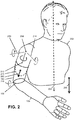
- the shoulder joint 209 is assumed to be a ball joint, and therefore has three degrees of freedom, described by flexion/extension, abduction/adduction, and internal/external rotation (as shown in FIG. 2 ).
- the location 307 of the powered elbow joint 108 relative to the body centerline 204 can be regarded as the elbow position in the Cartesian frame, while the angles of the elbow joint 108 and the shoulder joint 209 can be regarded as the elbow and shoulder joint angles in the configuration frame.
- shoulder flexion/extension and abduction/adduction in the configuration frame generally result in elbow movement in the Cartesian frame, while shoulder internal/external rotation in the configuration frame results in re-orientation of the elbow joint in the Cartesian frame, but not elbow joint movement through the Cartesian frame.
- the controller 116 can cause the powered elbow joint 108 to be extended (in the configuration frame) in relation to the linear distance between the elbow and body centerline. If the shoulder joint 209 moves the powered elbow joint 108 toward the body 202, the controller 116 configures the powered elbow joint 108 to be flexed in relation to the distance between the powered elbow joint 108 and the centerline 204.
- the estimated distance 309 can then be computed by the control 116 as a function of the orientation of the upper arm portion 201 (which can be used to approximate shoulder configuration) and the known length 310 from the intact shoulder joint 209 to the powered elbow joint 108.
- an alternate estimation is to use only the spatial orientation of the upper arm portion 102 to estimate the distance between the powered elbow joint 108 and centerline 204.
- the elbow angular velocity is essentially proportional to the component of velocity with which the powered elbow joint is moving away from or towards the centerline 204 (where away from results in an extensive angular velocity and towards results in a flexive angular velocity).
- the operation of the reaching mode can be further refined by using the orientation of the powered elbow joint 108 in relation to the shoulder joint 209 in order to further specify the action for the powered elbow joint 108.
- the movement of the powered elbow joint 108 can occur in relation to the projection of shoulder joint movement onto the plane orthogonal to the elbow joint axis of rotation (which is the plane containing the forearm portion 106 and the upper arm portion 102). In this manner, only shoulder joint movement in substantially the same plane as potential elbow joint movement will cause the controller 116 to generate coordinated movement in the powered elbow joint 108.
- detecting reaching with the shoulder joint 209 in a plane substantially orthogonal to the current axis of elbow joint rotation 218 will cause the controller 116 to generate simultaneous coordinated reaching with the powered elbow joint 108, while reaching with the shoulder joint 209 in a substantially different plane will not cause the controller 116 to generate a simultaneous coordinated movement of the powered elbow joint 108.
- the user can control whether or not coordinated reaching, using the powered elbow joint 108, will occur by orienting the shoulder appropriately.
- This approach is essentially the same as using the rotation about the long axis of the humerus bone (i.e., internal/external rotation 212 of the shoulder) to control the extent to which elbow flexion/extension is linked to elbow movement in the inertial reference frame.
- the controller 116 can be configured such that the coordinated action between the shoulder joint 209 and powered elbow joint 108 only occurs in a preselected plane.
- the controller 116 can be configured to provide coordinated action only when the arm prosthesis 100 is oriented essentially in the sagittal plane.
- the controller 116 can be configured to coordinate action only when the arm prosthesis 100 is oriented essentially in the frontal or mid-sagittal planes.
- the controller 116 utilizes the measured movement of the upper arm 104 to generate flexion or extension of the powered elbow joint 108, where the extra degrees-of-freedom in the shoulder joint 209 (three in the shoulder relative to one in the elbow) are used to modulate the relationship between movement of the upper arm portion 104 and movement of the powered elbow joint 108.
- the controller 116 can also be configured to combine an IMS coordinated control approach with EMG measurement from the upper arm (i.e., from the biceps and triceps muscle groups) to modify the IMS coordinated control approach.
- standard EMG control in which the differential amplitude of the EMG signals is used to command an angular velocity of the powered elbow joint 108, can be superimposed on the IMS coordinated control approach, which has the effect of moderating or modifying the coordinated control action by superimposing an elbow angular velocity command from the EMG onto the elbow angular velocity command from the IMS.
- a sustained co-contraction of the biceps and triceps musculature (as measured via EMG sensors 114) can be used by the controller 116 to lock out the influence of the IMS 118, such that movement of the upper arm portion 104 does not affect movement of the powered elbow joint 108 while the user is co-contracting musculature in the residual limb. Note that this approach has a biological analog, since a healthy individual will generally co-contract agonist/antagonist musculature in order to prevent a joint from moving.
- the strength of co-contraction can be used by the controller 116 to inversely modulate the gain of the previously described IMS coordinated control approach (e.g., modulate the gain relating the extension and flexion angular velocity of the powered elbow joint 108 to the component of linear velocity away from and toward, respectively, the body centerline 204).
- a strong co-contraction would essentially cause the controller 116 to zero the gain (i.e., lock the powered elbow joint 108, and decouple motion of the powered elbow joint 108 from motion in the shoulder joint 209), while a weak co-contraction would cause the controller 116 to slightly attenuate the gain (i.e., maintain but slightly lessen the coupling between motion in the shoulder joint and motion in the powered elbow joint 108).
- movement of the upper arm portion 104 can be used by the controller 116 to effectively lock out differential (velocity-based) EMG control of the powered elbow joint 108.
- the absence of motion in the shoulder joint 209 can be used by the controller 116 to enable standard EMG-based differential velocity control. Therefore, when the controller 116 detects that the shoulder joint 209 (and the upper arm portion 104) is moving, the powered elbow joint 108 is controlled using a IMS-based coordination controller (potentially modulated by EMG co-contraction), and when the shoulder joint 209 (and the upper arm portion 104) are not moving, the controller 116 reverts to the standard EMG-based differential velocity control.
- controller 116 With this control architecture implemented in controller 116, if the user co-contracts strongly while moving the upper arm portion 104, the IMS controller is locked out and the controller 116 essentially operates as a standard differential EMG velocity controller. By lessening the strength of the co-contraction during movement of the upper arm portion 104 (and the shoulder joint 209), the controller 116 complements the traditional (differential EMG) control method with the previously described IMS-based coordinated control approach. In this manner, the user can independently control movement of the powered elbow joint 108 when desired, and can alternatively leverage coordinated control of the shoulder joint 209 and powered elbow joint 108 movement when desired.
- the controller 116 can be configured so that the coordination between the powered elbow joint 108 and shoulder 209 can be such that the forearm portion 102 remains at a fixed orientation relative to the inertial reference frame for shoulder movement in the plane orthogonal to the axis 218 of the powered elbow joint 108.
- the axis 218 of the powered elbow joint 108 is orthogonal to the vertical, then movement of the shoulder joint 208 such that the upper arm portion 104 moves in the vertical plane will control the powered elbow joint 108 such that the forearm portion 102 remains at the same angle with respect to the vertical.
- the axis 218 of the powered elbow joint 108 is orthogonal to the horizontal plane, movement of the shoulder that moves the upper arm in the horizontal plane will maintain the orientation of the forearm portion 104 relative to an inertial reference frame in the horizontal plane.
- the projection of the angle of the forearm portion 104 with respect to the inertial reference frame onto the plane orthogonal to the axis 218 of the powered elbow joint 108 will remain invariant.
- the prescribed angle at which the forearm portion 104 remains invariant with respect to the inertial reference frame can be adjusted by the controller 116 by using EMG input from the residual limb in a manner similar to the typical myoelectric control of the powered elbow joint 108.
- EMG control of the angle of the powered elbow joint 108 can be superimposed onto the coordinated control of the powered elbow joint 108, such that the movement of the powered elbow joint 108 is both a function of EMG and movement of the shoulder joint 209.
- the controller 116 may be configured to allow the user to switch between a coordinated control mode and a strictly sequential control mode.
- the control approach will automatically switch into standard differential EMG velocity control in the absence of movement of shoulder joint 209 (as detected via IMS 118).
- the user can switch between these modes by a co-contraction pulse of both the biceps and triceps muscles, which is a commonly used method for switching control between joints in a multi-joint arm or for selecting various modes of operation.
- the switching signal can be a single co-contraction or a pattern of multiple co-contractions.
- the user can switch between modes via the IMS 118.
- the user can perform a specific movement and the IMS 118 then generates a set of signals that causes the controller 116 switch between modes.
- the user can perform a sudden abduction of the shoulder joint 209, which can be used to indicate that the user would like to switch between the coordinated and sequential control modes.
- information from the two sensors can be combined, such that switching is indicated by a co-contraction (as measured via EMG 114) and simultaneous sudden movement of the shoulder joint (as measured by the IMS 118).
- the arm prosthesis 100 can contain a powered wrist joint 112, as described above with respect to FIG. 1 .
- the IMS 118 can be used to determine the orientation of the prosthetic hand 110 relative to the inertial reference frame.
- the configuration of the arm prosthesis 100 is generally known and the orientation of its various components can therefore be determined based off a single IMS.
- the present technology is not limited in this regard and an IMS can be additionally provided for prosthetic hand 110.
- the joints of the arm prosthesis 100 can be coordinated with the movement of the shoulder joint 209 to maintain the prosthetic hand 110 in a prescribed orientation.
- the prosthetic hand 110 can be rotated about the axis of the arm prosthesis 100 either by pronation supination of the wrist or by internal and external rotation of the shoulder.
- the powered wrist joint 112 would provide an equal and opposite wrist pronation or supination, such that the hand would not rotate relative to the inertial reference frame. Flexion and extension or ulnar and radial deviation can be controlled similarly.
- This mode of operation can be switched by an EMG or IMS event, or some combination thereof.
- a sustained EMG co-contraction would cause the wrist to operate in this mode for the duration of the sustained co-contraction.
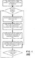
- the prosthetic arm prosthesis 100 can be initialized. In some configurations, this merely involves the powering the controller 116 in arm prosthesis 100. Optionally, this can involve manually selecting a mode of operation. That is, a user could select to operate the arm prosthesis 100 in a conventional EMG mode or allow the arm prosthesis 100 to auto-select between the conventional EMG mode and a coordinated control mode based on motion, orientation, and configuration information for the arm prosthesis 100, as described above. In such configurations, a mechanical switch can be provided on arm prosthesis 100, the mode can be selected at step 404 based on co-contractions detected by EMG sensors 114, or some other methodology can be provided for setting this operation mode at step 404.
- the method 400 can thereafter proceed to step 404.
- step 404 it is determined whether the EMG mode has been manually selected or not. If the EMG mode has been manually selected at 404, the method can proceed to step 412, discussed in further detail below. Otherwise, the method proceeds to step 406.
- step 406 sensor information for the prosthetic arm prosthesis 100 is received by controller 116.
- This sensor information can include, for example, signals from IMS 118, signals from EMG sensors 114, configuration/position information for joints in arm prosthesis 100 (e.g., powered elbow joint 108, wrist joint 112, and/or joints in prosthetic hand 110), or any combination thereof.
- controller 116 the method proceeds to step 408.
- step 408 the current motion, orientation, and configuration of arm prosthesis 100, and thus that of the residual limb by way of upper arm portion 102, with respect to the inertial reference frame, is computed.
- the information obtained at step 408 for the arm prosthesis 100 and the residual limb is utilized at step 410 to auto-select a mode of operation for the arm prosthesis 100.
- the arm prosthesis 100 can be operated in a coordinated control mode or a conventional EMG control mode based on the orientation of the arm prosthesis 100 and/or control signals being received (e.g., signals from EMG sensors 114).
- control signals being received e.g., signals from EMG sensors 114.
- the type of coordinated control or even the type of conventional EMG control to be provided for arm prosthesis 100 can also vary based on the current motion, orientation, or the configuration of the arm prosthesis 100.
- the control signals appropriate for the current control mode can be generated at step 412 and the prosthetic arm prosthesis 100 is operated.
- the joints are operated conventionally, based on signals from EMG sensors 114.
- the control signals can be based solely on the current motion, orientation, and configuration of the arm prosthesis 100.
- these control signals can also be based on a combination of the current motion, orientation, and configuration and the control signals provided by the user via EMG sensors 114.
- EMG signals can be used to modulate or modify the motion in a particular mode.
- steps 406, 408, 410, and 412 are repeated continuously.
- a determination can be made as to whether the current operation mode has changed. That is, whether the controller detects the user manually selecting going to the EMG control mode or the auto-select mode of operation. If there is no change, the method proceeds to repeat method 400 starting with step 406. Otherwise, the method proceeds to repeat method 400 starting with step 404.
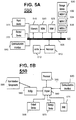
- FIG. 5A, and FIG. 5B illustrate exemplary possible system embodiments for a controller for carrying out the various embodiments in accordance with the present technology.
- the more appropriate embodiment will be apparent to those of ordinary skill in the art when practicing the present technology. Persons of ordinary skill in the art will also readily appreciate that other system embodiments are possible.
- FIG. 5A illustrates a conventional system bus computing system architecture 500 wherein the components of the system are in electrical communication with each other using a bus 505.
- Exemplary system 500 includes a processing unit (CPU or processor) 510 and a system bus 505 that couples various system components including the system memory 515, such as read only memory (ROM) 520 and random access memory (RAM) 525, to the processor 510.
- the system 500 can include a cache of high-speed memory connected directly with, in close proximity to, or integrated as part of the processor 510.
- the system 500 can copy data from the memory 515 and/or the storage device 530 to the cache 512 for quick access by the processor 510. In this way, the cache can provide a performance boost that avoids processor 510 delays while waiting for data.
- the processor 510 can include any general purpose processor and a hardware module or software module, such as module 1 532, module 2 534, and module 3 536 stored in storage device 530, configured to control the processor 510 as well as a special-purpose processor where software instructions are incorporated into the actual processor design.
- the processor 510 may essentially be a completely self-contained computing system, containing multiple cores or processors, a bus, memory controller, cache, etc.
- a multi-core processor may be symmetric or asymmetric.
- an input device 545 can represent any number of input mechanisms, such as a microphone for speech, a touch-sensitive screen for gesture or graphical input, keyboard, mouse, motion input, speech and so forth.
- An output device 535 can also be one or more of a number of output mechanisms known to those of skill in the art.
- multimodal systems can enable a user to provide multiple types of input to communicate with the computing device 500.
- the communications interface 540 can generally govern and manage the user input and system output. There is no restriction on operating on any particular hardware arrangement and therefore the basic features here may easily be substituted for improved hardware or firmware arrangements as they are developed.
- Storage device 530 is a non-volatile memory and can be a hard disk or other types of computer readable media which can store data that are accessible by a computer, such as magnetic cassettes, flash memory cards, solid state memory devices, digital versatile disks, cartridges, random access memories (RAMs) 525, read only memory (ROM) 520, and hybrids thereof.
- RAMs random access memories
- ROM read only memory
- the storage device 530 can include software modules 532, 534, 536 for controlling the processor 510. Other hardware or software modules are contemplated.
- the storage device 530 can be connected to the system bus 505.
- a hardware module that performs a particular function can include the software component stored in a computer-readable medium in connection with the necessary hardware components, such as the processor 510, bus 505, display 535, and so forth, to carry out the function.
- FIG. 5B illustrates a computer system 550 having a chipset architecture that can be used in executing the described method and generating and displaying a graphical user interface (GUI).
- Computer system 550 is an example of computer hardware, software, and firmware that can be used to implement the disclosed technology.
- System 550 can include a processor 555, representative of any number of physically and/or logically distinct resources capable of executing software, firmware, and hardware configured to perform identified computations.
- Processor 555 can communicate with a chipset 560 that can control input to and output from processor 555.
- chipset 560 outputs information to output 565, such as a display, and can read and write information to storage device 570, which can include magnetic media, and solid state media, for example.
- Chipset 560 can also read data from and write data to RAM 575.
- a bridge 580 for interfacing with a variety of user interface components 585 can be provided for interfacing with chipset 560.
- Such user interface components 585 can include a keyboard, a microphone, touch detection and processing circuitry, a pointing device, such as a mouse, and so on.
- inputs to system 550 can come from any of a variety of sources, machine generated and/or human generated.
- Chipset 560 can also interface with one or more communication interfaces 590 that can have different physical interfaces.
- Such communication interfaces can include interfaces for wired and wireless local area networks, for broadband wireless networks, as well as personal area networks.
- Some applications of the methods for generating, displaying, and using the GUI disclosed herein can include receiving ordered datasets over the physical interface or be generated by the machine itself by processor 555 analyzing data stored in storage 570 or 575. Further, the machine can receive inputs from a user via user interface components 585 and execute appropriate functions, such as browsing functions by interpreting these inputs using processor 555.
- exemplary systems 500 and 550 can have more than one processor 510 or be part of a group or cluster of computing devices networked together to provide greater processing capability.
- the present technology may be presented as including individual functional blocks including functional blocks comprising devices, device components, steps or routines in a method embodied in software, or combinations of hardware and software.
- the computer-readable storage devices, mediums, and memories can include a cable or wireless signal containing a bit stream and the like.
- non-transitory computer-readable storage media expressly exclude media such as energy, carrier signals, electromagnetic waves, and signals per se.
- Such instructions can comprise, for example, instructions and data which cause or otherwise configure a general purpose computer, special purpose computer, or special purpose processing device to perform a certain function or group of functions. Portions of computer resources used can be accessible over a network.
- the computer executable instructions may be, for example, binaries, intermediate format instructions such as assembly language, firmware, or source code. Examples of computer-readable media that may be used to store instructions, information used, and/or information created during methods according to described examples include magnetic or optical disks, flash memory, USB devices provided with non-volatile memory, networked storage devices, and so on.
- Devices implementing methods according to these disclosures can comprise hardware, firmware and/or software, and can take any of a variety of form factors. Typical examples of such form factors include laptops, smart phones, small form factor personal computers, personal digital assistants, and so on. Functionality described herein also can be embodied in peripherals or add-in cards. Such functionality can also be implemented on a circuit board among different chips or different processes executing in a single device, by way of further example.
- the instructions, media for conveying such instructions, computing resources for executing them, and other structures for supporting such computing resources are means for providing the functions described in these disclosures.
Description
- The present invention relates to control of arm prostheses, and more specifically to apparatus and methods for coordinating operation of joints in myoelectric arm prostheses.
- In many conventional myoelectric arm prostheses with a powered elbow joint, the configuration of the powered elbow joint is typically controlled irrespective of the configuration of the shoulder joint, and the wrist joint is typically controlled irrespective of the configuration of the other major joints in the arm. Further, in such myoelectric arm prostheses, the configuration of each joint in the prosthetic arm is typically controlled in a sequential manner (i.e., one joint is moved at a time), until the arm is configured in a desired posture. An exemplary embodiment of a method for control of a prostethic arm of the prior art is disclosed in
US 2011/264238 A1 . - The reason that conventional myoelectric prostheses are typically configured in a sequential manner is that the at least one joint of the myoelectric arm prosthesis is typically controlled with input from a pair of electromyogram (EMG) measurements, each of which measures the electrical activity resulting from a muscle contraction in a pair of opposing muscles in the residual limb of the amputated arm. In the case of an above-elbow amputation, the EMG is typically measured from the biceps and triceps muscle groups. In the anatomical arm, the combination of the pair of measurements provides a single bidirectional control for flexing or extending a given joint. Although the biceps and triceps muscles no longer act to flex and extend an anatomical elbow joint in above-elbow amputees, filtered and rectified EMG measurements can provide a real-time electrical signal proportional to the strength of contraction of the respective muscles in the residual limb. In most myoelectric arm prostheses, this electrical signal drives an elbow motor control loop for the prosthesis, such that the angular velocity of the prosthetic elbow joint is proportional to the measured EMG, where EMG is measured from the biceps muscle group for flexion and EMG is measured from the triceps muscle group for extension. Therefore, the angular speed of the elbow joint is generally proportional to the strength of contraction. In the absence of muscle contraction, the elbow remains locked at its current position (i.e., the joints of a myoelectric prosthetic arm are normally-locked). This control method can be referred to as differential, velocity-based EMG control.
- In the case of an arm prosthesis with powered elbow and wrist joints, coordinated control of these joints is typically not possible since only a single control signal (from the biceps and triceps) is available for controlling these multiple joints. As a result, the EMG control signal is typically switched between joints, resulting in the joints being controlled in a sequential fashion. For example, the EMG from biceps/triceps will first be used to move the prosthetic elbow joint. Thereafter, control may be switched to the wrist joint (typically by momentarily co-contracting both the biceps and triceps in unison, rather than using them in a differential sense) and the EMG from the biceps/triceps can adjust the angle of the wrist. A further momentary co-contraction will switch control to a prosthetic hand, such that the same EMG will open/close the hand. A subsequent momentary co-contraction will cycle EMG control back to the elbow joint. As such, the same agonist/antagonist muscle group (in this case biceps and triceps) provide myoelectric control of all of the joints and the hand of the prosthetic arm.
- With respect to coordinated control of the powered elbow joint and the intact shoulder joint in an above-elbow prosthesis, the powered elbow unit could be moved in concert with the shoulder, but not without great difficulty. In particular, since substantial portions of both the biceps and triceps extend over the shoulder joint (i.e., both are two-joint muscle groups), movement of the intact shoulder also produces myoelectric signals in the biceps and triceps. Therefore it is difficult, if not impossible, particularly without elbow proprioception, for the amputee to provide EMG signals to control the prosthetic elbow joint that are decoupled from EMG signals generated during use of the intact shoulder joint. As a result, the amputee typically resorts to the independent, sequential configuring of the shoulder and elbow joints, which removes the interference that shoulder movement presents in the biceps and triceps EMG signals. Therefore, above-elbow amputees are typically forced to move all joints of the arm in a sequential manner.
- The present technology is directed to systems and methods as set out in the claims. In particular configurations, the residual limb is the upper arm. The inertial measurement of the upper arm motion can be a measurement of upper arm spatial orientation and/or angular velocity with respect to an inertial reference frame.
- The elbow joint angular movement is controlled as a function of the upper arm spatial orientation, such that the elbow joint moves in extension when the upper arm orientation indicates that the elbow is moving away from the body, and such that the elbow joint moves in flexion when the upper arm orientation indicates that the elbow is moving closer to or toward the body. The movement of the elbow toward or away from the body can be indicated by the radial distance of the elbow from the body centerline.
- In some configurations, an elbow joint angular velocity can be caused by an instantaneous linear velocity of the elbow joint in a direction orthogonal to both the elbow axis of rotation and the long axis of the upper arm. Accordingly, the elbow joint angle can move in flexion when the instantaneous linear velocity is toward the body centerline and move in extension when the velocity is away from the body centerline.
- In still other configurations, an angular velocity of the elbow joint can be caused by an angular velocity of the upper arm with respect to an inertial reference frame. The angular velocity of the upper arm can be the component of angular velocity along the rotational axis of the elbow joint. Alternatively, the angular velocity of the upper arm can be the vector sum of angular velocity components in the plane orthogonal to the long axis of the upper arm. In some cases, the angle of shoulder internal/external rotation is used to modulate a gain between elbow joint angular velocity and upper arm angular velocity.
- In particular configurations, the elbow joint can be controlled such that the orientation of the forearm with respect to the inertial reference frame remains invariant for upper arm movement in the plane orthogonal to the axis of the elbow joint.
- In the various configurations, electromyogram (EMG) control of the elbow joint can be combined with IMS control of the elbow joint. In some cases, the EMG from the upper arm can be combined with measured orientation of the upper arm from the IMS to cause movement of the elbow joint. Further, a differential EMG elbow angular velocity control can be superimposed onto the IMS control.
- Additionally, a sustained co-contraction as indicated by EMG can be used to prevent elbow joint movement or attenuate elbow joint movement in relation to the strength of co-contraction.
- In some configurations, an angular velocity of the upper arm can be used to prevent differential EMG control of elbow joint movement. Alternatively, absence of angular velocity of the upper arm can switch control of elbow joint motion to differential EMG control.
- In some configurations, the prosthesis can be switched between the coordinated control mode and a sequential control mode. This switching can be based on at least an EMG or an IMS event.
- In some configurations, the at least one powered joint can include a powered wrist joint. The powered wrist joint can be controlled such that the orientation of the hand remains invariant relative to the inertial reference frame. Further, a co-contraction of muscles in the residual limb can be used to select the coordinated wrist control mode.
-
-
FIG. 1 shows a schematic illustration of a prosthetic arm in accordance with the present technology; -
FIGs. 2 and3 illustrates a user with the prosthetic arm ofFIG. 1 ; -
FIG. 4 shows a flowchart of steps in an exemplary method according to the present technology; and -
FIGs. 5A and 5B show a system embodiment suitable for implementing the control system of the present technology. - The present invention is described with reference to the attached figures, wherein like reference numerals are used throughout the figures to designate similar or equivalent elements. The figures are not drawn to scale and they are provided merely to illustrate the instant invention. Several aspects of the invention are described below with reference to example applications for illustration. It should be understood that numerous specific details, relationships, and methods are set forth to provide a full understanding of the invention. One having ordinary skill in the relevant art, however, will readily recognize that the invention can be practiced without one or more of the specific details or with other methods. In other instances, well-known structures or operations are not shown in detail to avoid obscuring the invention. The present invention is not limited by the illustrated ordering of acts or events, as some acts may occur in different orders and/or concurrently with other acts or events. Furthermore, not all illustrated acts or events are required to implement a methodology in accordance with the present invention.
- This present technology is directed to a control methodology that enables above-elbow amputees with myoelectric prostheses to effect coordinated, simultaneous movements of their anatomical shoulder joints and prosthetic elbow joints. In subjects with a healthy or intact arm, the major joints (i.e., shoulder, elbow, and possibly wrist) are typically controlled simultaneously in order to achieve a desired configuration of the arm. Configuring all joints simultaneously provides a number of important advantages relative to configuring them sequentially. The most obvious is that sequential configuration requires more time than simultaneous configuration of the joints, assuming the time required to configure each joint is essentially invariant. Therefore, obtaining a desired posture with simultaneous configuration of the joints enables a faster movement of the arm. Perhaps more significantly, a user is often interested in following a given path with his or her hand, rather than simply achieving a given final position of the hand. For example, in a reaching motion, or in opening a door or a drawer, the desired movement involves configuring the arm such that the hand follows a path or a trajectory, rather than simply obtaining a single pose with the arm.
- As is known in the study of robot manipulators, the ability to move the endpoint (in this case, the hand) of a multi-joint manipulator (in this case, the arm) along an arbitrary path requires the simultaneous movement of multiple joints in the arm. For example, for a two-joint manipulator consisting of a one-axis shoulder and one-axis elbow joint, moving the endpoint (i.e., hand) in a straight line path requires the simultaneous movement of both the shoulder and elbow joints. If the joints are moved sequentially, the path is instead constrained to move along one of two arc-shaped paths (an arc with a center located either at the shoulder or elbow, depending on which joint is being sequentially moved). Thus, the inability to configure multiple joints in a serial manipulator (i.e., arm) simultaneously increases the time to achieve a given configuration, and restricts severely the ability to move the hand along a generalizable path or trajectory.
- In view of the limitations of existing myoelectric prostheses, the present technology is directed to a control methodology that enables above-elbow amputees with myoelectric prostheses to effect coordinated, simultaneous movements of their anatomical shoulder joints and prosthetic elbow joints. Although the invention will be described primarily with respect to coordinating the control of a prosthetic elbow joint in an above-elbow myoelectric arm with the movement of the intact shoulder joint, the methodology of the present technology is also more broadly applicable to above-elbow and below-elbow myoelectric arms with wrist joints.
- Turning first to
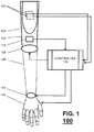
FIG. 1 , there is shown an above-elbowmyoelectric arm prosthesis 100 in accordance with the present technology. As shown inFIG. 1 , thearm prosthesis 100 includes anupper arm portion 102, with asocket 104 for receiving a residual limb, aforearm portion 106, and a powered elbow joint 108 rotatably coupling theforearm portion 106 and theupper arm portion 102. The powered elbow joint 108 can be configured to provide extension or flexion of thearm prosthesis 100. - A distal end of the
forearm portion 106, thearm prosthesis 100 can include ahand portion 110. Thehand portion 110 can include one or more powered joints. Further, although thehand portion 110 is shown as a hand-type terminal device, thehand portion 110 can be a non-anthropomorphic terminal device, such as a hook-type device. - The
hand portion 110 can be coupled via awrist joint 112. In some configurations, the wrist joint 112 can be passive. However, in other configurations, the wrist joint 112 can be powered as well and provide motion along one or more degrees of freedom. - As noted above, the
arm prosthesis 100 can be controlled myoelectrically. Accordingly, the arm can includeEMG sensors 114 for detecting EMG signals generated by different muscle groups. Additionally, thearm prosthesis 100 can include acontroller 116 for receiving the EMG signals fromEMG sensors 114 and for generating control signals for the elbow joint 108 and, if needed, for a wrist joint 112 andhand 110. - In addition to the above-mentioned components, which provide basic myoelectric operation of
arm prosthesis 100, as previously described, thearm prosthesis 100 can also include components to support the coordinated control of joints in accordance with the present technology. - In particular, the arm prosthesis can include an inertial measurement unit (IMS) 118 that can be used to compute in real-time the motion (relative to an inertial reference frame) of the
upper arm portion 102, and therefore estimate the motion of wearer's residual limb. As used herein, the motion information obtained based on theIMS 118 can encompass one or more of displacement or position, direction, velocity, acceleration, and time. In a particular embodiment, the IMS is located on theforearm portion 106 ofarm prosthesis 100, although it can be located on any part ofarm prosthesis 100. In some embodiments,IMS 118 can comprise a 3-axis gyroscope from which an angular velocity can be computed in multiple directions or axes. In other embodiments, theIMS 118 can comprise a single-axis gyroscope from which the angular velocity can be along a single direction or axis. In still other embodiments,IMS 118 can comprise accelerometers, gyroscopes, and potentially magnetometers. For example, in one particular embodiment,IMS 118 is a nine-axis IMS that includes a 3-axis accelerometer, a 3-axis gyroscope, and a 3-axis magnetometer. The data from these elements can then be used bycontroller 116 to compute the 3-dimensional orientation of theupper arm portion 102 and thus estimate the 3-dimensional orientation of a residual limb insocket 104 in real-time. The computation for a nine-axis IMS, such asIMS 118, is described below. - In general, a 3-axis magnetometer provides a low-frequency measure of the direction of the magnetic north vector (relative to the Earth, or inertial-reference frame). The 3-axis accelerometer provides a low-frequency measure of the direction of the gravity vector (relative to the Earth frame) and the 3-axis gyroscope provides angular velocities about each of the IMS's principal axes. The measured orientations of the magnetic north and gravity vectors can be used to compute an orthonormal basis of vectors (u1, u2, u3) of the reference frame for the IMU. This orthonormal basis represents the three-dimensional orientation of the IMU relative to the inertial reference frame (IRF), and can be computed from:


- Concatenating this set of vectors forms a rotation matrix which represents the steady state orientation of the IMS. Since the accelerometer and magnetometer generally provide low-frequency (essentially steady-state) measurements, this information can be combined with the measured angular velocity from the gyroscope to provide high-frequency measurement.
- Specifically, the gyroscope provides angular velocities about each principal axis of the IMS, which are integrated to calculate an estimation of the angular position of the IMS. Since the integration may result in drift over a prolonged period, only the high-frequency information from the gyroscope is used. By using a complementary filter approach to combine the low-frequency information from the magnetometer and accelerometer with the high-frequency information from the gyroscope, the three sensing modalities of the 9-axis IMS can provide a single rotation matrix with good accuracy and dynamic response, thus providing a real-time measurement of IMS orientation.
- Referring back to
FIG. 1 , theIMS 118 is shown as being located onupper arm portion 102 ofarm prosthesis 100. However, since all configuration angles withinarm prosthesis 100 are known, the motion ofupper arm portion 102 can be computed, and that of residual arm as well, regardless of the location of theIMS 118 inarm prosthesis 100. Thus, theIMS 118 can be located anywhere onarm prosthesis 100 in the various embodiments. For example, if theIMS 118 is situated on the forearm of the arm prosthesis, and if the elbow joint angle is measured (e.g., with an angular position sensor such as a rotary encoder), the orientation and motion of the wearer's upper arm (i.e., residual limb) can be determined relative to the inertial reference frame. Using the orientation or angular velocity information from theIMS 118, thecontroller 116 can then be used to coordinate motion of the powered joints inarm prosthesis 100 with that of the intact shoulder joint, as illustrated inFIG. 2 . In particular, assuming the upper body 202 (i.e., torso) of the user remains relatively stationary in or near a known configuration (e.g., acenter line 204 of the upper body is approximately parallel to a gravity vector 206), the configuration or movement of theshoulder joint 209 can also be estimated by thecontroller 116 in real-time based on the orientation orangular velocity information 208 obtained usingIMS 118 for theresidual limb 210. In particular, theIMS information 208 can be utilized by thecontroller 116 to extrapolate shoulder movement inrotation 212, abduction/adduction 214, and/or flexion/extension. Based on this estimate of shoulder motion and/or configuration, therotation 218 of the powered elbow joint 108 can be specified bycontroller 116 such that it moves in a coordinated fashion with the shoulder joint. Thus, thecontroller 116 can be configured to provide movement coordination between the powered elbow joint 118 and the (intact)shoulder joint 209. This coordinated movement can be independent of the EMG measurements from the residual limb, or can be modulated by or coordinated with the EMG input patterns to modify the pattern of coordination between the elbow and shoulder joints. - In one particular embodiment, the
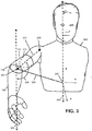
controller 116 can be configured to operate thearm prosthesis 100 in a reaching mode. In the reaching mode, the powered elbow joint 118 is flexed or extended in relation to the estimated distance 302 between alocation 307 of thepowered elbow 118 andapproximate centerline 204 of thebody 202. In the reaching mode, it is also important to distinguish between the elbowjoint location 307, which is a function of the upper arm orientation (and therefore a function of shoulder angle), and the elbow jointangular position 306, which is the angle formed between theforearm portion 106 andupper arm portion 102. The powered elbowjoint location 307 can be identified by three Cartesian coordinates with respect to areference 308 alongcenterline 204, while the elbow joint angle 306 (or elbow angle) is a scalar (since the powered elbow joint 108 is assumed to be a hinge, and thus has a single degree of freedom). The elbowjoint angle 306 is described anatomically as elbow flexion and extension, where flexion decreases the angle between theforearm portion 106 andupper arm portion 102, and extension increases it. Theshoulder joint 209 is assumed to be a ball joint, and therefore has three degrees of freedom, described by flexion/extension, abduction/adduction, and internal/external rotation (as shown inFIG. 2 ). - The
location 307 of the powered elbow joint 108 relative to thebody centerline 204 can be regarded as the elbow position in the Cartesian frame, while the angles of the elbow joint 108 and theshoulder joint 209 can be regarded as the elbow and shoulder joint angles in the configuration frame. Note that shoulder flexion/extension and abduction/adduction in the configuration frame generally result in elbow movement in the Cartesian frame, while shoulder internal/external rotation in the configuration frame results in re-orientation of the elbow joint in the Cartesian frame, but not elbow joint movement through the Cartesian frame. - In the reaching mode, if the
shoulder joint 209 moves the powered elbow joint 108 away from the body 202 (in the Cartesian frame), thecontroller 116 can cause the powered elbow joint 108 to be extended (in the configuration frame) in relation to the linear distance between the elbow and body centerline. If theshoulder joint 209 moves the powered elbow joint 108 toward thebody 202, thecontroller 116 configures the powered elbow joint 108 to be flexed in relation to the distance between the powered elbow joint 108 and thecenterline 204. The estimateddistance 309 can then be computed by thecontrol 116 as a function of the orientation of the upper arm portion 201 (which can be used to approximate shoulder configuration) and the knownlength 310 from theintact shoulder joint 209 to the powered elbow joint 108. Alternatively, an alternate estimation is to use only the spatial orientation of theupper arm portion 102 to estimate the distance between the powered elbow joint 108 andcenterline 204. In this approach, the elbow angular velocity is essentially proportional to the component of velocity with which the powered elbow joint is moving away from or towards the centerline 204 (where away from results in an extensive angular velocity and towards results in a flexive angular velocity). - The operation of the reaching mode can be further refined by using the orientation of the powered elbow joint 108 in relation to the
shoulder joint 209 in order to further specify the action for the powered elbow joint 108. In particular, the movement of the powered elbow joint 108 can occur in relation to the projection of shoulder joint movement onto the plane orthogonal to the elbow joint axis of rotation (which is the plane containing theforearm portion 106 and the upper arm portion 102). In this manner, only shoulder joint movement in substantially the same plane as potential elbow joint movement will cause thecontroller 116 to generate coordinated movement in the powered elbow joint 108. Therefore, detecting reaching with theshoulder joint 209 in a plane substantially orthogonal to the current axis of elbowjoint rotation 218 will cause thecontroller 116 to generate simultaneous coordinated reaching with the powered elbow joint 108, while reaching with theshoulder joint 209 in a substantially different plane will not cause thecontroller 116 to generate a simultaneous coordinated movement of the powered elbow joint 108. In this manner, the user can control whether or not coordinated reaching, using the powered elbow joint 108, will occur by orienting the shoulder appropriately. This approach is essentially the same as using the rotation about the long axis of the humerus bone (i.e., internal/external rotation 212 of the shoulder) to control the extent to which elbow flexion/extension is linked to elbow movement in the inertial reference frame. - In some configurations, the
controller 116 can be configured such that the coordinated action between theshoulder joint 209 and powered elbow joint 108 only occurs in a preselected plane. For example, thecontroller 116 can be configured to provide coordinated action only when thearm prosthesis 100 is oriented essentially in the sagittal plane. Alternatively, thecontroller 116 can be configured to coordinate action only when thearm prosthesis 100 is oriented essentially in the frontal or mid-sagittal planes. In all cases, thecontroller 116 utilizes the measured movement of theupper arm 104 to generate flexion or extension of the powered elbow joint 108, where the extra degrees-of-freedom in the shoulder joint 209 (three in the shoulder relative to one in the elbow) are used to modulate the relationship between movement of theupper arm portion 104 and movement of the powered elbow joint 108. - In addition to using the
IMS 118 to command flexion and extension of the powered elbow joint 108, thecontroller 116 can also be configured to combine an IMS coordinated control approach with EMG measurement from the upper arm (i.e., from the biceps and triceps muscle groups) to modify the IMS coordinated control approach. In one embodiment, standard EMG control, in which the differential amplitude of the EMG signals is used to command an angular velocity of the powered elbow joint 108, can be superimposed on the IMS coordinated control approach, which has the effect of moderating or modifying the coordinated control action by superimposing an elbow angular velocity command from the EMG onto the elbow angular velocity command from the IMS. - In another embodiment of the controller, a sustained co-contraction of the biceps and triceps musculature (as measured via EMG sensors 114) can be used by the
controller 116 to lock out the influence of theIMS 118, such that movement of theupper arm portion 104 does not affect movement of the powered elbow joint 108 while the user is co-contracting musculature in the residual limb. Note that this approach has a biological analog, since a healthy individual will generally co-contract agonist/antagonist musculature in order to prevent a joint from moving. - In a variation of this approach, the strength of co-contraction (as measured via EMG sensor 114) can be used by the
controller 116 to inversely modulate the gain of the previously described IMS coordinated control approach (e.g., modulate the gain relating the extension and flexion angular velocity of the powered elbow joint 108 to the component of linear velocity away from and toward, respectively, the body centerline 204). A strong co-contraction would essentially cause thecontroller 116 to zero the gain (i.e., lock the powered elbow joint 108, and decouple motion of the powered elbow joint 108 from motion in the shoulder joint 209), while a weak co-contraction would cause thecontroller 116 to slightly attenuate the gain (i.e., maintain but slightly lessen the coupling between motion in the shoulder joint and motion in the powered elbow joint 108). - In some embodiments, movement of the upper arm portion 104 (as detected by IMS 118) can be used by the
controller 116 to effectively lock out differential (velocity-based) EMG control of the powered elbow joint 108. Additionally, the absence of motion in the shoulder joint 209 (and thus in upper arm portion 104) can be used by thecontroller 116 to enable standard EMG-based differential velocity control. Therefore, when thecontroller 116 detects that the shoulder joint 209 (and the upper arm portion 104) is moving, the powered elbow joint 108 is controlled using a IMS-based coordination controller (potentially modulated by EMG co-contraction), and when the shoulder joint 209 (and the upper arm portion 104) are not moving, thecontroller 116 reverts to the standard EMG-based differential velocity control. - With this control architecture implemented in
controller 116, if the user co-contracts strongly while moving theupper arm portion 104, the IMS controller is locked out and thecontroller 116 essentially operates as a standard differential EMG velocity controller. By lessening the strength of the co-contraction during movement of the upper arm portion 104 (and the shoulder joint 209), thecontroller 116 complements the traditional (differential EMG) control method with the previously described IMS-based coordinated control approach. In this manner, the user can independently control movement of the powered elbow joint 108 when desired, and can alternatively leverage coordinated control of theshoulder joint 209 and powered elbow joint 108 movement when desired. - In a different embodiment, the
controller 116 can be configured so that the coordination between the powered elbow joint 108 andshoulder 209 can be such that theforearm portion 102 remains at a fixed orientation relative to the inertial reference frame for shoulder movement in the plane orthogonal to theaxis 218 of the powered elbow joint 108. For example, if theaxis 218 of the powered elbow joint 108 is orthogonal to the vertical, then movement of theshoulder joint 208 such that theupper arm portion 104 moves in the vertical plane will control the powered elbow joint 108 such that theforearm portion 102 remains at the same angle with respect to the vertical. If theaxis 218 of the powered elbow joint 108 is orthogonal to the horizontal plane, movement of the shoulder that moves the upper arm in the horizontal plane will maintain the orientation of theforearm portion 104 relative to an inertial reference frame in the horizontal plane. When moved in a different plane, the projection of the angle of theforearm portion 104 with respect to the inertial reference frame onto the plane orthogonal to theaxis 218 of the powered elbow joint 108 will remain invariant. - Further, in this embodiment, the prescribed angle at which the
forearm portion 104 remains invariant with respect to the inertial reference frame can be adjusted by thecontroller 116 by using EMG input from the residual limb in a manner similar to the typical myoelectric control of the powered elbow joint 108. Thus, EMG control of the angle of the powered elbow joint 108 can be superimposed onto the coordinated control of the powered elbow joint 108, such that the movement of the powered elbow joint 108 is both a function of EMG and movement of theshoulder joint 209. - In all embodiments of the control methodology of the present technology, it may be useful for the
controller 116 to be configured to allow the user to switch between a coordinated control mode and a strictly sequential control mode. In a preferred embodiment, the control approach will automatically switch into standard differential EMG velocity control in the absence of movement of shoulder joint 209 (as detected via IMS 118). In another embodiment, the user can switch between these modes by a co-contraction pulse of both the biceps and triceps muscles, which is a commonly used method for switching control between joints in a multi-joint arm or for selecting various modes of operation. The switching signal can be a single co-contraction or a pattern of multiple co-contractions. - Alternatively, the user can switch between modes via the
IMS 118. In particular, the user can perform a specific movement and theIMS 118 then generates a set of signals that causes thecontroller 116 switch between modes. For example, the user can perform a sudden abduction of theshoulder joint 209, which can be used to indicate that the user would like to switch between the coordinated and sequential control modes. Alternatively, information from the two sensors can be combined, such that switching is indicated by a co-contraction (as measured via EMG 114) and simultaneous sudden movement of the shoulder joint (as measured by the IMS 118). - In some embodiments, the
arm prosthesis 100 can contain a powered wrist joint 112, as described above with respect toFIG. 1 . In such embodiments, theIMS 118 can be used to determine the orientation of theprosthetic hand 110 relative to the inertial reference frame. For example, as noted above, the configuration of thearm prosthesis 100 is generally known and the orientation of its various components can therefore be determined based off a single IMS. However, the present technology is not limited in this regard and an IMS can be additionally provided forprosthetic hand 110. - When switched into a wrist control mode, the joints of the
arm prosthesis 100 can be coordinated with the movement of theshoulder joint 209 to maintain theprosthetic hand 110 in a prescribed orientation. For example, when the powered elbow joint 108 is fully extended, theprosthetic hand 110 can be rotated about the axis of thearm prosthesis 100 either by pronation supination of the wrist or by internal and external rotation of the shoulder. In this coordinated control mode, if theshoulder joint 209 were internally or externally rotated, the powered wrist joint 112 would provide an equal and opposite wrist pronation or supination, such that the hand would not rotate relative to the inertial reference frame. Flexion and extension or ulnar and radial deviation can be controlled similarly. This mode of operation can be switched by an EMG or IMS event, or some combination thereof. In a preferred embodiment, a sustained EMG co-contraction would cause the wrist to operate in this mode for the duration of the sustained co-contraction. - Now turning to
FIG. 4 , there is shown a flowchart of steps in anexemplary method 400 for coordinated control of a prosthetic arm in accordance with the present technology. The method begins atstep 402. Atstep 402, theprosthetic arm prosthesis 100 can be initialized. In some configurations, this merely involves the powering thecontroller 116 inarm prosthesis 100. Optionally, this can involve manually selecting a mode of operation. That is, a user could select to operate thearm prosthesis 100 in a conventional EMG mode or allow thearm prosthesis 100 to auto-select between the conventional EMG mode and a coordinated control mode based on motion, orientation, and configuration information for thearm prosthesis 100, as described above. In such configurations, a mechanical switch can be provided onarm prosthesis 100, the mode can be selected atstep 404 based on co-contractions detected byEMG sensors 114, or some other methodology can be provided for setting this operation mode atstep 404. - In the case of manual mode selection, the
method 400 can thereafter proceed to step 404. Atstep 404 it is determined whether the EMG mode has been manually selected or not. If the EMG mode has been manually selected at 404, the method can proceed to step 412, discussed in further detail below. Otherwise, the method proceeds to step 406. - After the initialization of the
prosthetic arm prosthesis 100 atstep 402 and, optionally, the determination atstep 404 that auto-selection of mode is desired, the method can proceed to step 406. Atstep 406, sensor information for theprosthetic arm prosthesis 100 is received bycontroller 116. This sensor information can include, for example, signals fromIMS 118, signals fromEMG sensors 114, configuration/position information for joints in arm prosthesis 100 (e.g., powered elbow joint 108, wrist joint 112, and/or joints in prosthetic hand 110), or any combination thereof. Once the sensor information is received bycontroller 116 atstep 406, the method proceeds to step 408. At step 408, the current motion, orientation, and configuration ofarm prosthesis 100, and thus that of the residual limb by way ofupper arm portion 102, with respect to the inertial reference frame, is computed. - Thereafter, the information obtained at step 408 for the
arm prosthesis 100 and the residual limb is utilized atstep 410 to auto-select a mode of operation for thearm prosthesis 100. As noted above, thearm prosthesis 100 can be operated in a coordinated control mode or a conventional EMG control mode based on the orientation of thearm prosthesis 100 and/or control signals being received (e.g., signals from EMG sensors 114). Further, as also noted above, the type of coordinated control or even the type of conventional EMG control to be provided forarm prosthesis 100 can also vary based on the current motion, orientation, or the configuration of thearm prosthesis 100. - Once the control mode is auto-selected at step 408 (or a manual EMG control mode is determined at step 404), the control signals appropriate for the current control mode can be generated at
step 412 and theprosthetic arm prosthesis 100 is operated. In an EMG control mode, the joints are operated conventionally, based on signals fromEMG sensors 114. In a coordinated control mode, the control signals can be based solely on the current motion, orientation, and configuration of thearm prosthesis 100. However, as also discussed above, these control signals can also be based on a combination of the current motion, orientation, and configuration and the control signals provided by the user viaEMG sensors 114. For example, as discussed above, EMG signals can be used to modulate or modify the motion in a particular mode. - Thereafter, steps 406, 408, 410, and 412 are repeated continuously. Optionally, after
step 412, a determination can be made as to whether the current operation mode has changed. That is, whether the controller detects the user manually selecting going to the EMG control mode or the auto-select mode of operation. If there is no change, the method proceeds to repeatmethod 400 starting withstep 406. Otherwise, the method proceeds to repeatmethod 400 starting withstep 404. -
FIG. 5A, and FIG. 5B illustrate exemplary possible system embodiments for a controller for carrying out the various embodiments in accordance with the present technology. The more appropriate embodiment will be apparent to those of ordinary skill in the art when practicing the present technology. Persons of ordinary skill in the art will also readily appreciate that other system embodiments are possible. -
FIG. 5A illustrates a conventional system buscomputing system architecture 500 wherein the components of the system are in electrical communication with each other using abus 505.Exemplary system 500 includes a processing unit (CPU or processor) 510 and asystem bus 505 that couples various system components including thesystem memory 515, such as read only memory (ROM) 520 and random access memory (RAM) 525, to theprocessor 510. Thesystem 500 can include a cache of high-speed memory connected directly with, in close proximity to, or integrated as part of theprocessor 510. Thesystem 500 can copy data from thememory 515 and/or thestorage device 530 to thecache 512 for quick access by theprocessor 510. In this way, the cache can provide a performance boost that avoidsprocessor 510 delays while waiting for data. These and other modules can control or be configured to control theprocessor 510 to perform various actions.Other system memory 515 may be available for use as well. Thememory 515 can include multiple different types of memory with different performance characteristics. Theprocessor 510 can include any general purpose processor and a hardware module or software module, such as module 1 532,module 2 534, and module 3 536 stored instorage device 530, configured to control theprocessor 510 as well as a special-purpose processor where software instructions are incorporated into the actual processor design. Theprocessor 510 may essentially be a completely self-contained computing system, containing multiple cores or processors, a bus, memory controller, cache, etc. A multi-core processor may be symmetric or asymmetric. - To enable user interaction with the
computing device 500, aninput device 545 can represent any number of input mechanisms, such as a microphone for speech, a touch-sensitive screen for gesture or graphical input, keyboard, mouse, motion input, speech and so forth. Anoutput device 535 can also be one or more of a number of output mechanisms known to those of skill in the art. In some instances, multimodal systems can enable a user to provide multiple types of input to communicate with thecomputing device 500. Thecommunications interface 540 can generally govern and manage the user input and system output. There is no restriction on operating on any particular hardware arrangement and therefore the basic features here may easily be substituted for improved hardware or firmware arrangements as they are developed. -
Storage device 530 is a non-volatile memory and can be a hard disk or other types of computer readable media which can store data that are accessible by a computer, such as magnetic cassettes, flash memory cards, solid state memory devices, digital versatile disks, cartridges, random access memories (RAMs) 525, read only memory (ROM) 520, and hybrids thereof. - The
storage device 530 can includesoftware modules processor 510. Other hardware or software modules are contemplated. Thestorage device 530 can be connected to thesystem bus 505. In one aspect, a hardware module that performs a particular function can include the software component stored in a computer-readable medium in connection with the necessary hardware components, such as theprocessor 510,bus 505,display 535, and so forth, to carry out the function. -
FIG. 5B illustrates acomputer system 550 having a chipset architecture that can be used in executing the described method and generating and displaying a graphical user interface (GUI).Computer system 550 is an example of computer hardware, software, and firmware that can be used to implement the disclosed technology.System 550 can include aprocessor 555, representative of any number of physically and/or logically distinct resources capable of executing software, firmware, and hardware configured to perform identified computations.Processor 555 can communicate with achipset 560 that can control input to and output fromprocessor 555. In this example,chipset 560 outputs information tooutput 565, such as a display, and can read and write information tostorage device 570, which can include magnetic media, and solid state media, for example.Chipset 560 can also read data from and write data to RAM 575. Abridge 580 for interfacing with a variety ofuser interface components 585 can be provided for interfacing withchipset 560. Suchuser interface components 585 can include a keyboard, a microphone, touch detection and processing circuitry, a pointing device, such as a mouse, and so on. In general, inputs tosystem 550 can come from any of a variety of sources, machine generated and/or human generated. -
Chipset 560 can also interface with one ormore communication interfaces 590 that can have different physical interfaces. Such communication interfaces can include interfaces for wired and wireless local area networks, for broadband wireless networks, as well as personal area networks. Some applications of the methods for generating, displaying, and using the GUI disclosed herein can include receiving ordered datasets over the physical interface or be generated by the machine itself byprocessor 555 analyzing data stored instorage user interface components 585 and execute appropriate functions, such as browsing functions by interpreting theseinputs using processor 555. - It can be appreciated that
exemplary systems processor 510 or be part of a group or cluster of computing devices networked together to provide greater processing capability. - For clarity of explanation, in some instances the present technology may be presented as including individual functional blocks including functional blocks comprising devices, device components, steps or routines in a method embodied in software, or combinations of hardware and software.
- In some embodiments the computer-readable storage devices, mediums, and memories can include a cable or wireless signal containing a bit stream and the like. However, when mentioned, non-transitory computer-readable storage media expressly exclude media such as energy, carrier signals, electromagnetic waves, and signals per se.
- Methods according to the above-described examples can be implemented using computer-executable instructions that are stored or otherwise available from computer readable media. Such instructions can comprise, for example, instructions and data which cause or otherwise configure a general purpose computer, special purpose computer, or special purpose processing device to perform a certain function or group of functions. Portions of computer resources used can be accessible over a network. The computer executable instructions may be, for example, binaries, intermediate format instructions such as assembly language, firmware, or source code. Examples of computer-readable media that may be used to store instructions, information used, and/or information created during methods according to described examples include magnetic or optical disks, flash memory, USB devices provided with non-volatile memory, networked storage devices, and so on.
- Devices implementing methods according to these disclosures can comprise hardware, firmware and/or software, and can take any of a variety of form factors. Typical examples of such form factors include laptops, smart phones, small form factor personal computers, personal digital assistants, and so on. Functionality described herein also can be embodied in peripherals or add-in cards. Such functionality can also be implemented on a circuit board among different chips or different processes executing in a single device, by way of further example.
- The instructions, media for conveying such instructions, computing resources for executing them, and other structures for supporting such computing resources are means for providing the functions described in these disclosures.
- While various embodiments of the present invention have been described above, it should be understood that they have been presented by way of example only, and not limitation. Numerous changes to the disclosed embodiments can be made in accordance with the disclosure herein without departing from the scope of the invention. Thus, the breadth and scope of the present invention should not be limited by any of the above described embodiments. Rather, the scope of the invention should be defined in accordance with the following claims and their equivalents.
- Although the invention has been illustrated and described with respect to one or more implementations, equivalent alterations and modifications will occur to others skilled in the art upon the reading and understanding of this specification and the annexed drawings. In addition, while a particular feature of the invention may have been disclosed with respect to only one of several implementations, such feature may be combined with one or more other features of the other implementations as may be desired and advantageous for any given or particular application.
- The terminology used herein is for the purpose of describing particular embodiments only and is not intended to be limiting of the invention. As used herein, the singular forms "a", "an" and "the" are intended to include the plural forms as well, unless the context clearly indicates otherwise. Furthermore, to the extent that the terms "including", "includes", "having", "has", "with", or variants thereof are used in either the detailed description and/or the claims, such terms are intended to be inclusive in a manner similar to the term "comprising."
- Unless otherwise defined, all terms (including technical and scientific terms) used herein have the same meaning as commonly understood by one of ordinary skill in the art to which this invention belongs. Also, the terms "about", "substantially", "essentially", and "approximately", as used herein with respect to a stated value, property, or condition are intend to indicate being within 20% or less of the stated value, property, or condition unless otherwise specified above. It will be further understood that terms, such as those defined in commonly used dictionaries, should be interpreted as having a meaning that is consistent with their meaning in the context of the relevant art and will not be interpreted in an idealized or overly formal sense unless expressly so defined herein.
Claims (13)
- A method for the control of an arm prosthesis (100) having at least one powered joint (108, 112) and at least one inertial measurement sensor (IMS) (118), characterized in that the method comprising:determining (406, 408) a motion of the arm prosthesis relative to the inertial reference frame based at least on an output of the IMS;
generating (410, 412) control signals for the at least one powered joint based on the motion and the orientation of the prosthetic arm,
wherein the at least one powered joint comprises a powered elbow joint (108), wherein the IMS measures the motion of an upper arm portion (102) of the arm prosthesis, and wherein the generating the control signals comprises controlling an angular movement of the powered elbow joint based on the motion of the upper arm; and wherein the generating of control signals comprises:determining a motion of the powered elbow joint with respect to a body (202) of a user based on the orientation and motion of the arm prosthesis with respect to the body;configuring the control signals to move the powered elbow joint in extension when the powered elbow joint is moving away from the body; and
configuring the control signals to move the powered elbow joint in flexion when the powered elbow joint is moving closer toward the body. - The method of claim 1, wherein determining the motion of the powered elbow joint with respect to the body comprises determining a change in at least one of a radial distance (309) from the powered elbow joint to at least one of a centerline (204) of the body or a distance of the powered elbow joint from a preselected plane relative to the body.
- The method of claim 1, wherein the generating of control signals comprises:
determining a velocity vector (208) for the powered elbow joint with respect to a body (204) of a user in a direction orthogonal to both an axis of rotation of the powered elbow joint and a long axis of the upper arm portion based on the orientation and motion of the arm prosthesis with respect to the body - The method of claim 1, wherein the generating of control signals comprises:determining an angular velocity (208) of the upper arm portion with respect to the inertial reference frame; andconfiguring the control signals to move the powered elbow joint according to the angular velocity.
- The method of claim 4, further comprising determining an angle of internal/external shoulder rotation (212).
- The method of claim 1, wherein the generating of control signals further comprises:determining whether the upper arm portion is moving in a plane orthogonal to the axis of the powered elbow joint; andupon determining that the upper arm portion is moving in a plane orthogonal to the axis of the powered elbow joint, configuring the control signals to maintain an orientation of a forearm portion of the arm prosthesis invariant.
- The method of any of claims 1 to 6, wherein the control signals also comprise electromyogram (EMG) signals, and wherein the generating of the control signals further comprises modulating an amount of motion of the at least one powered joint based on the EMG signals.
- The method of claim 7, where a sustained co-contraction as indicated by EMG attenuates the amount of motion based on a strength of the co-contraction.
- The method of any of claims 1-8, further comprising:selecting (410) a mode of operating the at least one powered joint based at least on the motion of the upper arm portion; andconfiguring (412) the control signals based on the selected mode.
- The method of claim 1, where the at least one powered joint is a powered wrist joint (112) between a forearm portion (106) and a hand portion (110) of the prosthetic arm.
- The method of claim 9, where the configuring of the control signals comprises configuring the control signals for the powered wrist joint to maintain an orientation of the hand portion invariant relative to the inertial reference frame.
- A computer-readable medium having stored thereon a computer program for controlling a prosthetic arm, characterized in that the computer program comprising a plurality of instructions for carrying out the method of any of claims 1 to 11.
- A control system (116) for a prosthetic arm (100) comprising an upper arm portion (102), a forearm portion (106), a powered elbow joint (108), and an inertial measurement sensor (118), the control system comprising:a processor (510); anda computer readable medium (530), characterized in that the computer readable medium having stored thereon a plurality of instructions for causing the processor to perform the steps of any of claims 1 to 11.
Applications Claiming Priority (2)
| Application Number | Priority Date | Filing Date | Title |
|---|---|---|---|
| US201361818596P | 2013-05-02 | 2013-05-02 | |
| PCT/US2014/036599 WO2014179704A1 (en) | 2013-05-02 | 2014-05-02 | Coordinated control for an arm prosthesis |
Publications (3)
| Publication Number | Publication Date |
|---|---|
| EP2991592A1 EP2991592A1 (en) | 2016-03-09 |
| EP2991592B1 EP2991592B1 (en) | 2017-07-19 |
| EP2991592B2 true EP2991592B2 (en) | 2020-07-01 |
Family
ID=50981849
Family Applications (1)
| Application Number | Title | Priority Date | Filing Date |
|---|---|---|---|
| EP14732473.5A Active EP2991592B2 (en) | 2013-05-02 | 2014-05-02 | Coordinated control for an arm prosthesis |
Country Status (5)
| Country | Link |
|---|---|
| US (2) | US10092423B2 (en) |
| EP (1) | EP2991592B2 (en) |
| CA (1) | CA2910346A1 (en) |
| ES (1) | ES2642123T5 (en) |
| WO (1) | WO2014179704A1 (en) |
Cited By (1)
| Publication number | Priority date | Publication date | Assignee | Title |
|---|---|---|---|---|
| CN109407531A (en) * | 2018-10-30 | 2019-03-01 | 深圳市心流科技有限公司 | Intelligent home furnishing control method, device and computer readable storage medium |
Families Citing this family (27)
| Publication number | Priority date | Publication date | Assignee | Title |
|---|---|---|---|---|
| US8956421B2 (en) | 2007-02-06 | 2015-02-17 | Deka Products Limited Partnership | Dynamic support apparatus and system |
| US9114030B2 (en) * | 2007-02-06 | 2015-08-25 | Deka Products Limited Partnership | System for control of a prosthetic device |
| CA2679616C (en) | 2007-02-06 | 2015-10-06 | David E. Altobelli | Dynamic support apparatus |
| US9114028B2 (en) | 2007-02-06 | 2015-08-25 | Deka Products Limited Partnership | Arm prosthetic device |
| US8979943B2 (en) | 2007-02-06 | 2015-03-17 | Deka Products Limited Partnership | Arm prosthetic device |
| US8864845B2 (en) | 2007-02-06 | 2014-10-21 | DEKA Limited Partnership | System for control of a prosthetic device |
| WO2008098059A2 (en) | 2007-02-06 | 2008-08-14 | Deka Integrated Solutions Corp. | Method and apparatus for control of a prosthetic |
| US8449624B2 (en) | 2007-02-06 | 2013-05-28 | Deka Products Limited Partnership | Arm prosthetic device |
| ITPI20130004A1 (en) * | 2013-01-16 | 2014-07-17 | Machinale S R L Fab | PROSTHETIC STRUCTURE FOR HAND AMPUTATION |
| WO2014179704A1 (en) * | 2013-05-02 | 2014-11-06 | Vanderbilt University | Coordinated control for an arm prosthesis |
| WO2015061453A1 (en) * | 2013-10-22 | 2015-04-30 | Msssachusetts Institute Of Technology | Peripheral neural interface via nerve regeneration to distal tissues |
| EP3102158B1 (en) | 2014-02-04 | 2019-06-12 | Rehabilitation Institute of Chicago | Modular and lightweight prosthesis components |
| GB201403265D0 (en) | 2014-02-25 | 2014-04-09 | Touch Emas Ltd | Prosthetic digit for use with touchscreen devices |
| CN104997582B (en) * | 2015-07-30 | 2017-03-22 | 沈阳工业大学 | Device and method for controlling intelligent artificial limb based on eye and lower jaw electromyographic signals |
| CN105082174B (en) * | 2015-08-14 | 2017-10-10 | 哈尔滨工大服务机器人有限公司 | A kind of clothes Robot model two-freedom active elbow joint drive device |
| US11179251B2 (en) | 2016-01-08 | 2021-11-23 | Massachusetts Institute Of Technology | Method and system for providing proprioceptive feedback and functionality mitigating limb pathology |
| CN106236336A (en) * | 2016-08-15 | 2016-12-21 | 中国科学院重庆绿色智能技术研究院 | A kind of myoelectric limb gesture and dynamics control method |
| WO2018132711A1 (en) * | 2017-01-12 | 2018-07-19 | Deka Products Limited Partnership | Prosthetic device |
| CN107684501B (en) * | 2017-09-07 | 2020-05-08 | 北京机械设备研究所 | Elbow joint action continuous identification method based on surface myoelectricity |
| US10973660B2 (en) | 2017-12-15 | 2021-04-13 | Touch Bionics Limited | Powered prosthetic thumb |
| CA3009219C (en) | 2018-06-21 | 2021-01-19 | Bionicarm Ltd. | Electrically driven artificial arm and method of use |
| EP3695813A1 (en) * | 2019-02-14 | 2020-08-19 | VBIONIC Sp. z o.o. | Active prosthetic wrist |
| KR102251364B1 (en) * | 2019-03-28 | 2021-05-12 | 근로복지공단 | Control system for hand motion of myoelectric hand and control method thereof |
| RU2744605C2 (en) * | 2019-07-24 | 2021-03-11 | Федеральное государственное бюджетное учреждение "ФЕДЕРАЛЬНЫЙ НАУЧНЫЙ ЦЕНТР РЕАБИЛИТАЦИИ ИНВАЛИДОВ ИМ. Г.А. АЛЬБРЕХТА" МИНИСТЕРСТВА ТРУДА И СОЦИАЛЬНОЙ ЗАЩИТЫ РОССИЙСКОЙ ФЕДЕРАЦИИ (ФГБУ "ФНЦРИ им. Альбрехта Минтруда России") | Multifunctional active shoulder prosthesis |
| CN110801317B (en) * | 2019-10-29 | 2021-09-21 | 德林义肢矫型器(北京)有限公司 | Artificial limb with elbow joint device |
| US11931270B2 (en) | 2019-11-15 | 2024-03-19 | Touch Bionics Limited | Prosthetic digit actuator |
| CN114176854B (en) * | 2021-11-30 | 2023-05-30 | 中国人民解放军总医院第四医学中心 | Multi-sensing acquisition and control system for osseointegration |
Citations (2)
| Publication number | Priority date | Publication date | Assignee | Title |
|---|---|---|---|---|
| WO2001043669A1 (en) † | 1999-12-17 | 2001-06-21 | Respecta Oy | Support device replacing the existence or function of a limb |
| WO2013010597A1 (en) † | 2011-07-20 | 2013-01-24 | Otto Bock Healthcare Gmbh | Device with a wall designed to tightly enclose a body part |
Family Cites Families (4)
| Publication number | Priority date | Publication date | Assignee | Title |
|---|---|---|---|---|
| US9114030B2 (en) * | 2007-02-06 | 2015-08-25 | Deka Products Limited Partnership | System for control of a prosthetic device |
| EP2429459B1 (en) * | 2009-04-13 | 2016-07-20 | DEKA Products Limited Partnership | System, method and apparatus for control of a prosthetic device |
| CA2761809C (en) * | 2010-02-16 | 2019-05-28 | Deka Products Limited Partnership | System, method and apparatus for control of a prosthetic device |
| WO2014179704A1 (en) * | 2013-05-02 | 2014-11-06 | Vanderbilt University | Coordinated control for an arm prosthesis |
-
2014
- 2014-05-02 WO PCT/US2014/036599 patent/WO2014179704A1/en active Application Filing
- 2014-05-02 CA CA2910346A patent/CA2910346A1/en not_active Abandoned
- 2014-05-02 EP EP14732473.5A patent/EP2991592B2/en active Active
- 2014-05-02 ES ES14732473T patent/ES2642123T5/en active Active
-
2015
- 2015-11-02 US US14/929,779 patent/US10092423B2/en active Active
-
2018
- 2018-10-09 US US16/155,150 patent/US10952877B2/en active Active
Patent Citations (2)
| Publication number | Priority date | Publication date | Assignee | Title |
|---|---|---|---|---|
| WO2001043669A1 (en) † | 1999-12-17 | 2001-06-21 | Respecta Oy | Support device replacing the existence or function of a limb |
| WO2013010597A1 (en) † | 2011-07-20 | 2013-01-24 | Otto Bock Healthcare Gmbh | Device with a wall designed to tightly enclose a body part |
Non-Patent Citations (1)
| Title |
|---|
| ALSHAMMARY N.A. ET AL.: "Assessment of a Multigrasp Myoelectric Control Approach for use by Transhumeral Amputees", CONF PROC IEEE ENGINEERING IN MEDICINE AND BIOLOGY SOCIETY, 25 June 2015 (2015-06-25) † |
Cited By (1)
| Publication number | Priority date | Publication date | Assignee | Title |
|---|---|---|---|---|
| CN109407531A (en) * | 2018-10-30 | 2019-03-01 | 深圳市心流科技有限公司 | Intelligent home furnishing control method, device and computer readable storage medium |
Also Published As
| Publication number | Publication date |
|---|---|
| ES2642123T5 (en) | 2021-04-06 |
| EP2991592A1 (en) | 2016-03-09 |
| US10952877B2 (en) | 2021-03-23 |
| EP2991592B1 (en) | 2017-07-19 |
| US20190105185A1 (en) | 2019-04-11 |
| US20160051383A1 (en) | 2016-02-25 |
| US10092423B2 (en) | 2018-10-09 |
| ES2642123T3 (en) | 2017-11-15 |
| WO2014179704A1 (en) | 2014-11-06 |
| CA2910346A1 (en) | 2014-11-06 |
Similar Documents
| Publication | Publication Date | Title |
|---|---|---|
| US10952877B2 (en) | Coordinated control for an arm prosthesis | |
| CN108874119B (en) | System and method for tracking arm movement to generate input for a computer system | |
| Fang et al. | 3D human gesture capturing and recognition by the IMMU-based data glove | |
| US10635166B2 (en) | Motion predictions of overlapping kinematic chains of a skeleton model used to control a computer system | |
| Baldi et al. | GESTO: A glove for enhanced sensing and touching based on inertial and magnetic sensors for hand tracking and cutaneous feedback | |
| US11474593B2 (en) | Tracking user movements to control a skeleton model in a computer system | |
| Fang et al. | A novel data glove using inertial and magnetic sensors for motion capture and robotic arm-hand teleoperation | |
| US10976863B1 (en) | Calibration of inertial measurement units in alignment with a skeleton model to control a computer system based on determination of orientation of an inertial measurement unit from an image of a portion of a user | |
| Fang et al. | Development of a wearable device for motion capturing based on magnetic and inertial measurement units | |
| Gunawardane et al. | Comparison of hand gesture inputs of leap motion controller & data glove in to a soft finger | |
| US11079860B2 (en) | Kinematic chain motion predictions using results from multiple approaches combined via an artificial neural network | |
| US20220155866A1 (en) | Ring device having an antenna, a touch pad, and/or a charging pad to control a computing device based on user motions | |
| CN108279773B (en) | Data glove based on MARG sensor and magnetic field positioning technology | |
| CN114503057A (en) | Orientation determination based on both image and inertial measurement units | |
| US20210109606A1 (en) | Automatic Switching between Different Modes of Tracking User Motions to Control Computer Applications | |
| WO2020009715A2 (en) | Tracking user movements to control a skeleton model in a computer system | |
| Mohammadi et al. | Fingertip force estimation via inertial and magnetic sensors in deformable object manipulation | |
| Zhang et al. | 3D upper limb motion modeling and estimation using wearable micro-sensors | |
| US20230011082A1 (en) | Combine Orientation Tracking Techniques of Different Data Rates to Generate Inputs to a Computing System | |
| Yang et al. | Research on human motion monitoring method based on multi-joint constraint filter model | |
| US20210318759A1 (en) | Input device to control a computing device with a touch pad having a curved surface configured to sense touch input | |
| Amir et al. | Sensor based human arm motion and gesture replication system using MATLAB | |
| Denz et al. | A high-accuracy, low-budget Sensor Glove for Trajectory Model Learning | |
| Wang et al. | Finger Tracking for Human Computer Interface Using Multiple Sensor Data Fusion | |
| Sauer et al. | RSQ Motion-a prototype of the motion analysis system in the joints |
Legal Events
| Date | Code | Title | Description |
|---|---|---|---|
| PUAI | Public reference made under article 153(3) epc to a published international application that has entered the european phase |
Free format text: ORIGINAL CODE: 0009012 |
|
| 17P | Request for examination filed |
Effective date: 20151030 |
|
| AK | Designated contracting states |
Kind code of ref document: A1 Designated state(s): AL AT BE BG CH CY CZ DE DK EE ES FI FR GB GR HR HU IE IS IT LI LT LU LV MC MK MT NL NO PL PT RO RS SE SI SK SM TR |
|
| AX | Request for extension of the european patent |
Extension state: BA ME |
|
| DAX | Request for extension of the european patent (deleted) | ||
| GRAP | Despatch of communication of intention to grant a patent |
Free format text: ORIGINAL CODE: EPIDOSNIGR1 |
|
| STAA | Information on the status of an ep patent application or granted ep patent |
Free format text: STATUS: GRANT OF PATENT IS INTENDED |
|
| INTG | Intention to grant announced |
Effective date: 20170127 |
|
| GRAS | Grant fee paid |
Free format text: ORIGINAL CODE: EPIDOSNIGR3 |
|
| GRAA | (expected) grant |
Free format text: ORIGINAL CODE: 0009210 |
|
| STAA | Information on the status of an ep patent application or granted ep patent |
Free format text: STATUS: THE PATENT HAS BEEN GRANTED |
|
| AK | Designated contracting states |
Kind code of ref document: B1 Designated state(s): AL AT BE BG CH CY CZ DE DK EE ES FI FR GB GR HR HU IE IS IT LI LT LU LV MC MK MT NL NO PL PT RO RS SE SI SK SM TR |
|
| REG | Reference to a national code |
Ref country code: GB Ref legal event code: FG4D |
|
| REG | Reference to a national code |
Ref country code: CH Ref legal event code: EP |
|
| REG | Reference to a national code |
Ref country code: IE Ref legal event code: FG4D |
|
| REG | Reference to a national code |
Ref country code: AT Ref legal event code: REF Ref document number: 909646 Country of ref document: AT Kind code of ref document: T Effective date: 20170815 |
|
| REG | Reference to a national code |
Ref country code: DE Ref legal event code: R096 Ref document number: 602014012018 Country of ref document: DE |
|
| REG | Reference to a national code |
Ref country code: ES Ref legal event code: FG2A Ref document number: 2642123 Country of ref document: ES Kind code of ref document: T3 Effective date: 20171115 |
|
| REG | Reference to a national code |
Ref country code: NL Ref legal event code: MP Effective date: 20170719 |
|
| REG | Reference to a national code |
Ref country code: LT Ref legal event code: MG4D |
|
| REG | Reference to a national code |
Ref country code: AT Ref legal event code: MK05 Ref document number: 909646 Country of ref document: AT Kind code of ref document: T Effective date: 20170719 |
|
| PG25 | Lapsed in a contracting state [announced via postgrant information from national office to epo] |
Ref country code: FI Free format text: LAPSE BECAUSE OF FAILURE TO SUBMIT A TRANSLATION OF THE DESCRIPTION OR TO PAY THE FEE WITHIN THE PRESCRIBED TIME-LIMIT Effective date: 20170719 Ref country code: LT Free format text: LAPSE BECAUSE OF FAILURE TO SUBMIT A TRANSLATION OF THE DESCRIPTION OR TO PAY THE FEE WITHIN THE PRESCRIBED TIME-LIMIT Effective date: 20170719 Ref country code: NO Free format text: LAPSE BECAUSE OF FAILURE TO SUBMIT A TRANSLATION OF THE DESCRIPTION OR TO PAY THE FEE WITHIN THE PRESCRIBED TIME-LIMIT Effective date: 20171019 Ref country code: SE Free format text: LAPSE BECAUSE OF FAILURE TO SUBMIT A TRANSLATION OF THE DESCRIPTION OR TO PAY THE FEE WITHIN THE PRESCRIBED TIME-LIMIT Effective date: 20170719 Ref country code: HR Free format text: LAPSE BECAUSE OF FAILURE TO SUBMIT A TRANSLATION OF THE DESCRIPTION OR TO PAY THE FEE WITHIN THE PRESCRIBED TIME-LIMIT Effective date: 20170719 Ref country code: NL Free format text: LAPSE BECAUSE OF FAILURE TO SUBMIT A TRANSLATION OF THE DESCRIPTION OR TO PAY THE FEE WITHIN THE PRESCRIBED TIME-LIMIT Effective date: 20170719 Ref country code: AT Free format text: LAPSE BECAUSE OF FAILURE TO SUBMIT A TRANSLATION OF THE DESCRIPTION OR TO PAY THE FEE WITHIN THE PRESCRIBED TIME-LIMIT Effective date: 20170719 |
|
| PG25 | Lapsed in a contracting state [announced via postgrant information from national office to epo] |
Ref country code: LV Free format text: LAPSE BECAUSE OF FAILURE TO SUBMIT A TRANSLATION OF THE DESCRIPTION OR TO PAY THE FEE WITHIN THE PRESCRIBED TIME-LIMIT Effective date: 20170719 Ref country code: PL Free format text: LAPSE BECAUSE OF FAILURE TO SUBMIT A TRANSLATION OF THE DESCRIPTION OR TO PAY THE FEE WITHIN THE PRESCRIBED TIME-LIMIT Effective date: 20170719 Ref country code: IS Free format text: LAPSE BECAUSE OF FAILURE TO SUBMIT A TRANSLATION OF THE DESCRIPTION OR TO PAY THE FEE WITHIN THE PRESCRIBED TIME-LIMIT Effective date: 20171119 Ref country code: GR Free format text: LAPSE BECAUSE OF FAILURE TO SUBMIT A TRANSLATION OF THE DESCRIPTION OR TO PAY THE FEE WITHIN THE PRESCRIBED TIME-LIMIT Effective date: 20171020 Ref country code: RS Free format text: LAPSE BECAUSE OF FAILURE TO SUBMIT A TRANSLATION OF THE DESCRIPTION OR TO PAY THE FEE WITHIN THE PRESCRIBED TIME-LIMIT Effective date: 20170719 Ref country code: BG Free format text: LAPSE BECAUSE OF FAILURE TO SUBMIT A TRANSLATION OF THE DESCRIPTION OR TO PAY THE FEE WITHIN THE PRESCRIBED TIME-LIMIT Effective date: 20171019 |
|
| REG | Reference to a national code |
Ref country code: DE Ref legal event code: R026 Ref document number: 602014012018 Country of ref document: DE |
|
| PLBI | Opposition filed |
Free format text: ORIGINAL CODE: 0009260 |
|
| PG25 | Lapsed in a contracting state [announced via postgrant information from national office to epo] |
Ref country code: DK Free format text: LAPSE BECAUSE OF FAILURE TO SUBMIT A TRANSLATION OF THE DESCRIPTION OR TO PAY THE FEE WITHIN THE PRESCRIBED TIME-LIMIT Effective date: 20170719 Ref country code: CZ Free format text: LAPSE BECAUSE OF FAILURE TO SUBMIT A TRANSLATION OF THE DESCRIPTION OR TO PAY THE FEE WITHIN THE PRESCRIBED TIME-LIMIT Effective date: 20170719 Ref country code: RO Free format text: LAPSE BECAUSE OF FAILURE TO SUBMIT A TRANSLATION OF THE DESCRIPTION OR TO PAY THE FEE WITHIN THE PRESCRIBED TIME-LIMIT Effective date: 20170719 |
|
| PLAX | Notice of opposition and request to file observation + time limit sent |
Free format text: ORIGINAL CODE: EPIDOSNOBS2 |
|
| REG | Reference to a national code |
Ref country code: FR Ref legal event code: PLFP Year of fee payment: 5 |
|
| 26 | Opposition filed |
Opponent name: OTTO BOCK HEALTHCARE PRODUCTS GMBH Effective date: 20180419 |
|
| PG25 | Lapsed in a contracting state [announced via postgrant information from national office to epo] |
Ref country code: EE Free format text: LAPSE BECAUSE OF FAILURE TO SUBMIT A TRANSLATION OF THE DESCRIPTION OR TO PAY THE FEE WITHIN THE PRESCRIBED TIME-LIMIT Effective date: 20170719 Ref country code: SK Free format text: LAPSE BECAUSE OF FAILURE TO SUBMIT A TRANSLATION OF THE DESCRIPTION OR TO PAY THE FEE WITHIN THE PRESCRIBED TIME-LIMIT Effective date: 20170719 Ref country code: SM Free format text: LAPSE BECAUSE OF FAILURE TO SUBMIT A TRANSLATION OF THE DESCRIPTION OR TO PAY THE FEE WITHIN THE PRESCRIBED TIME-LIMIT Effective date: 20170719 |
|
| PLBB | Reply of patent proprietor to notice(s) of opposition received |
Free format text: ORIGINAL CODE: EPIDOSNOBS3 |
|
| PG25 | Lapsed in a contracting state [announced via postgrant information from national office to epo] |
Ref country code: SI Free format text: LAPSE BECAUSE OF FAILURE TO SUBMIT A TRANSLATION OF THE DESCRIPTION OR TO PAY THE FEE WITHIN THE PRESCRIBED TIME-LIMIT Effective date: 20170719 |
|
| REG | Reference to a national code |
Ref country code: CH Ref legal event code: PL |
|
| REG | Reference to a national code |
Ref country code: BE Ref legal event code: MM Effective date: 20180531 |
|
| PG25 | Lapsed in a contracting state [announced via postgrant information from national office to epo] |
Ref country code: MC Free format text: LAPSE BECAUSE OF FAILURE TO SUBMIT A TRANSLATION OF THE DESCRIPTION OR TO PAY THE FEE WITHIN THE PRESCRIBED TIME-LIMIT Effective date: 20170719 |
|
| REG | Reference to a national code |
Ref country code: IE Ref legal event code: MM4A |
|
| PG25 | Lapsed in a contracting state [announced via postgrant information from national office to epo] |
Ref country code: CH Free format text: LAPSE BECAUSE OF NON-PAYMENT OF DUE FEES Effective date: 20180531 Ref country code: LI Free format text: LAPSE BECAUSE OF NON-PAYMENT OF DUE FEES Effective date: 20180531 |
|
| PG25 | Lapsed in a contracting state [announced via postgrant information from national office to epo] |
Ref country code: LU Free format text: LAPSE BECAUSE OF NON-PAYMENT OF DUE FEES Effective date: 20180502 |
|
| PG25 | Lapsed in a contracting state [announced via postgrant information from national office to epo] |
Ref country code: IE Free format text: LAPSE BECAUSE OF NON-PAYMENT OF DUE FEES Effective date: 20180502 |
|
| PG25 | Lapsed in a contracting state [announced via postgrant information from national office to epo] |
Ref country code: BE Free format text: LAPSE BECAUSE OF NON-PAYMENT OF DUE FEES Effective date: 20180531 |
|
| PG25 | Lapsed in a contracting state [announced via postgrant information from national office to epo] |
Ref country code: MT Free format text: LAPSE BECAUSE OF NON-PAYMENT OF DUE FEES Effective date: 20180502 |
|
| PG25 | Lapsed in a contracting state [announced via postgrant information from national office to epo] |
Ref country code: TR Free format text: LAPSE BECAUSE OF FAILURE TO SUBMIT A TRANSLATION OF THE DESCRIPTION OR TO PAY THE FEE WITHIN THE PRESCRIBED TIME-LIMIT Effective date: 20170719 |
|
| PG25 | Lapsed in a contracting state [announced via postgrant information from national office to epo] |
Ref country code: PT Free format text: LAPSE BECAUSE OF FAILURE TO SUBMIT A TRANSLATION OF THE DESCRIPTION OR TO PAY THE FEE WITHIN THE PRESCRIBED TIME-LIMIT Effective date: 20170719 |
|
| PUAH | Patent maintained in amended form |
Free format text: ORIGINAL CODE: 0009272 |
|
| STAA | Information on the status of an ep patent application or granted ep patent |
Free format text: STATUS: PATENT MAINTAINED AS AMENDED |
|
| PG25 | Lapsed in a contracting state [announced via postgrant information from national office to epo] |
Ref country code: CY Free format text: LAPSE BECAUSE OF FAILURE TO SUBMIT A TRANSLATION OF THE DESCRIPTION OR TO PAY THE FEE WITHIN THE PRESCRIBED TIME-LIMIT Effective date: 20170719 Ref country code: MK Free format text: LAPSE BECAUSE OF NON-PAYMENT OF DUE FEES Effective date: 20170719 Ref country code: HU Free format text: LAPSE BECAUSE OF FAILURE TO SUBMIT A TRANSLATION OF THE DESCRIPTION OR TO PAY THE FEE WITHIN THE PRESCRIBED TIME-LIMIT; INVALID AB INITIO Effective date: 20140502 |
|
| 27A | Patent maintained in amended form |
Effective date: 20200701 |
|
| AK | Designated contracting states |
Kind code of ref document: B2 Designated state(s): AL AT BE BG CH CY CZ DE DK EE ES FI FR GB GR HR HU IE IS IT LI LT LU LV MC MK MT NL NO PL PT RO RS SE SI SK SM TR |
|
| REG | Reference to a national code |
Ref country code: DE Ref legal event code: R102 Ref document number: 602014012018 Country of ref document: DE |
|
| PG25 | Lapsed in a contracting state [announced via postgrant information from national office to epo] |
Ref country code: AL Free format text: LAPSE BECAUSE OF FAILURE TO SUBMIT A TRANSLATION OF THE DESCRIPTION OR TO PAY THE FEE WITHIN THE PRESCRIBED TIME-LIMIT Effective date: 20170719 |
|
| PGFP | Annual fee paid to national office [announced via postgrant information from national office to epo] |
Ref country code: ES Payment date: 20200601 Year of fee payment: 7 |
|
| PGFP | Annual fee paid to national office [announced via postgrant information from national office to epo] |
Ref country code: IT Payment date: 20200522 Year of fee payment: 7 |
|
| REG | Reference to a national code |
Ref country code: ES Ref legal event code: DC2A Ref document number: 2642123 Country of ref document: ES Kind code of ref document: T5 Effective date: 20210406 |
|
| PGFP | Annual fee paid to national office [announced via postgrant information from national office to epo] |
Ref country code: GB Payment date: 20220527 Year of fee payment: 9 Ref country code: FR Payment date: 20220525 Year of fee payment: 9 Ref country code: DE Payment date: 20220527 Year of fee payment: 9 |
|
| REG | Reference to a national code |
Ref country code: ES Ref legal event code: FD2A Effective date: 20220801 |
|
| PG25 | Lapsed in a contracting state [announced via postgrant information from national office to epo] |
Ref country code: ES Free format text: LAPSE BECAUSE OF NON-PAYMENT OF DUE FEES Effective date: 20210503 |
|
| PG25 | Lapsed in a contracting state [announced via postgrant information from national office to epo] |
Ref country code: IT Free format text: LAPSE BECAUSE OF NON-PAYMENT OF DUE FEES Effective date: 20200502 |
|
| REG | Reference to a national code |
Ref country code: DE Ref legal event code: R119 Ref document number: 602014012018 Country of ref document: DE |
|
| GBPC | Gb: european patent ceased through non-payment of renewal fee |
Effective date: 20230502 |