EP2991374A1 - Ultrasound emission device - Google Patents
Ultrasound emission device Download PDFInfo
- Publication number
- EP2991374A1 EP2991374A1 EP13883272.0A EP13883272A EP2991374A1 EP 2991374 A1 EP2991374 A1 EP 2991374A1 EP 13883272 A EP13883272 A EP 13883272A EP 2991374 A1 EP2991374 A1 EP 2991374A1
- Authority
- EP
- European Patent Office
- Prior art keywords
- ultrasonic wave
- wave generation
- ventilation hole
- frame body
- lengthwise direction
- Prior art date
- Legal status (The legal status is an assumption and is not a legal conclusion. Google has not performed a legal analysis and makes no representation as to the accuracy of the status listed.)
- Withdrawn
Links
- 238000002604 ultrasonography Methods 0.000 title 1
- 238000009423 ventilation Methods 0.000 claims abstract description 89
- 239000000463 material Substances 0.000 description 20
- 239000010410 layer Substances 0.000 description 17
- 239000002585 base Substances 0.000 description 10
- 230000000052 comparative effect Effects 0.000 description 9
- 230000001070 adhesive effect Effects 0.000 description 6
- 239000000853 adhesive Substances 0.000 description 5
- 229910010293 ceramic material Inorganic materials 0.000 description 5
- 238000010586 diagram Methods 0.000 description 5
- 239000012790 adhesive layer Substances 0.000 description 3
- 239000000919 ceramic Substances 0.000 description 3
- 229910052751 metal Inorganic materials 0.000 description 3
- 239000002184 metal Substances 0.000 description 3
- XLYOFNOQVPJJNP-UHFFFAOYSA-N water Chemical compound O XLYOFNOQVPJJNP-UHFFFAOYSA-N 0.000 description 3
- 239000004593 Epoxy Substances 0.000 description 2
- 239000000956 alloy Substances 0.000 description 2
- 229910045601 alloy Inorganic materials 0.000 description 2
- PNEYBMLMFCGWSK-UHFFFAOYSA-N aluminium oxide Inorganic materials [O-2].[O-2].[O-2].[Al+3].[Al+3] PNEYBMLMFCGWSK-UHFFFAOYSA-N 0.000 description 2
- 239000013013 elastic material Substances 0.000 description 2
- 239000011521 glass Substances 0.000 description 2
- 238000004519 manufacturing process Methods 0.000 description 2
- 239000007769 metal material Substances 0.000 description 2
- 229910052763 palladium Inorganic materials 0.000 description 2
- 229910052709 silver Inorganic materials 0.000 description 2
- 239000003513 alkali Substances 0.000 description 1
- 239000000470 constituent Substances 0.000 description 1
- 230000000694 effects Effects 0.000 description 1
- 239000003822 epoxy resin Substances 0.000 description 1
- 238000000034 method Methods 0.000 description 1
- 229920000647 polyepoxide Polymers 0.000 description 1
- BITYAPCSNKJESK-UHFFFAOYSA-N potassiosodium Chemical compound [Na].[K] BITYAPCSNKJESK-UHFFFAOYSA-N 0.000 description 1
- 229920005989 resin Polymers 0.000 description 1
- 239000011347 resin Substances 0.000 description 1
- 229910000679 solder Inorganic materials 0.000 description 1
- 229920003002 synthetic resin Polymers 0.000 description 1
- 239000000057 synthetic resin Substances 0.000 description 1
Images




Classifications
-
- G—PHYSICS
- G10—MUSICAL INSTRUMENTS; ACOUSTICS
- G10K—SOUND-PRODUCING DEVICES; METHODS OR DEVICES FOR PROTECTING AGAINST, OR FOR DAMPING, NOISE OR OTHER ACOUSTIC WAVES IN GENERAL; ACOUSTICS NOT OTHERWISE PROVIDED FOR
- G10K9/00—Devices in which sound is produced by vibrating a diaphragm or analogous element, e.g. fog horns, vehicle hooters or buzzers
- G10K9/12—Devices in which sound is produced by vibrating a diaphragm or analogous element, e.g. fog horns, vehicle hooters or buzzers electrically operated
- G10K9/122—Devices in which sound is produced by vibrating a diaphragm or analogous element, e.g. fog horns, vehicle hooters or buzzers electrically operated using piezoelectric driving means
- G10K9/125—Devices in which sound is produced by vibrating a diaphragm or analogous element, e.g. fog horns, vehicle hooters or buzzers electrically operated using piezoelectric driving means with a plurality of active elements
-
- G—PHYSICS
- G10—MUSICAL INSTRUMENTS; ACOUSTICS
- G10K—SOUND-PRODUCING DEVICES; METHODS OR DEVICES FOR PROTECTING AGAINST, OR FOR DAMPING, NOISE OR OTHER ACOUSTIC WAVES IN GENERAL; ACOUSTICS NOT OTHERWISE PROVIDED FOR
- G10K9/00—Devices in which sound is produced by vibrating a diaphragm or analogous element, e.g. fog horns, vehicle hooters or buzzers
- G10K9/18—Details, e.g. bulbs, pumps, pistons, switches or casings
- G10K9/22—Mountings; Casings
-
- B—PERFORMING OPERATIONS; TRANSPORTING
- B06—GENERATING OR TRANSMITTING MECHANICAL VIBRATIONS IN GENERAL
- B06B—METHODS OR APPARATUS FOR GENERATING OR TRANSMITTING MECHANICAL VIBRATIONS OF INFRASONIC, SONIC, OR ULTRASONIC FREQUENCY, e.g. FOR PERFORMING MECHANICAL WORK IN GENERAL
- B06B1/00—Methods or apparatus for generating mechanical vibrations of infrasonic, sonic, or ultrasonic frequency
- B06B1/02—Methods or apparatus for generating mechanical vibrations of infrasonic, sonic, or ultrasonic frequency making use of electrical energy
- B06B1/06—Methods or apparatus for generating mechanical vibrations of infrasonic, sonic, or ultrasonic frequency making use of electrical energy operating with piezoelectric effect or with electrostriction
- B06B1/0603—Methods or apparatus for generating mechanical vibrations of infrasonic, sonic, or ultrasonic frequency making use of electrical energy operating with piezoelectric effect or with electrostriction using a piezoelectric bender, e.g. bimorph
-
- B—PERFORMING OPERATIONS; TRANSPORTING
- B06—GENERATING OR TRANSMITTING MECHANICAL VIBRATIONS IN GENERAL
- B06B—METHODS OR APPARATUS FOR GENERATING OR TRANSMITTING MECHANICAL VIBRATIONS OF INFRASONIC, SONIC, OR ULTRASONIC FREQUENCY, e.g. FOR PERFORMING MECHANICAL WORK IN GENERAL
- B06B1/00—Methods or apparatus for generating mechanical vibrations of infrasonic, sonic, or ultrasonic frequency
- B06B1/02—Methods or apparatus for generating mechanical vibrations of infrasonic, sonic, or ultrasonic frequency making use of electrical energy
- B06B1/06—Methods or apparatus for generating mechanical vibrations of infrasonic, sonic, or ultrasonic frequency making use of electrical energy operating with piezoelectric effect or with electrostriction
- B06B1/0607—Methods or apparatus for generating mechanical vibrations of infrasonic, sonic, or ultrasonic frequency making use of electrical energy operating with piezoelectric effect or with electrostriction using multiple elements
- B06B1/0611—Methods or apparatus for generating mechanical vibrations of infrasonic, sonic, or ultrasonic frequency making use of electrical energy operating with piezoelectric effect or with electrostriction using multiple elements in a pile
-
- B—PERFORMING OPERATIONS; TRANSPORTING
- B06—GENERATING OR TRANSMITTING MECHANICAL VIBRATIONS IN GENERAL
- B06B—METHODS OR APPARATUS FOR GENERATING OR TRANSMITTING MECHANICAL VIBRATIONS OF INFRASONIC, SONIC, OR ULTRASONIC FREQUENCY, e.g. FOR PERFORMING MECHANICAL WORK IN GENERAL
- B06B1/00—Methods or apparatus for generating mechanical vibrations of infrasonic, sonic, or ultrasonic frequency
- B06B1/02—Methods or apparatus for generating mechanical vibrations of infrasonic, sonic, or ultrasonic frequency making use of electrical energy
- B06B1/06—Methods or apparatus for generating mechanical vibrations of infrasonic, sonic, or ultrasonic frequency making use of electrical energy operating with piezoelectric effect or with electrostriction
- B06B1/0607—Methods or apparatus for generating mechanical vibrations of infrasonic, sonic, or ultrasonic frequency making use of electrical energy operating with piezoelectric effect or with electrostriction using multiple elements
- B06B1/0611—Methods or apparatus for generating mechanical vibrations of infrasonic, sonic, or ultrasonic frequency making use of electrical energy operating with piezoelectric effect or with electrostriction using multiple elements in a pile
- B06B1/0618—Methods or apparatus for generating mechanical vibrations of infrasonic, sonic, or ultrasonic frequency making use of electrical energy operating with piezoelectric effect or with electrostriction using multiple elements in a pile of piezo- and non-piezoelectric elements, e.g. 'Tonpilz'
-
- G—PHYSICS
- G01—MEASURING; TESTING
- G01S—RADIO DIRECTION-FINDING; RADIO NAVIGATION; DETERMINING DISTANCE OR VELOCITY BY USE OF RADIO WAVES; LOCATING OR PRESENCE-DETECTING BY USE OF THE REFLECTION OR RERADIATION OF RADIO WAVES; ANALOGOUS ARRANGEMENTS USING OTHER WAVES
- G01S7/00—Details of systems according to groups G01S13/00, G01S15/00, G01S17/00
- G01S7/52—Details of systems according to groups G01S13/00, G01S15/00, G01S17/00 of systems according to group G01S15/00
- G01S7/521—Constructional features
Definitions
- the present invention relates to an ultrasonic wave generation apparatus in which plate-shaped first and second vibrators vibrate at opposite phases.
- ultrasonic wave generation apparatuses have been used in rangefinding techniques and the like that employ ultrasonic waves.
- Patent Document 1 discloses an ultrasonic wave generation apparatus that uses a piezoelectric vibrator.
- This ultrasonic wave generation apparatus includes a housing and an ultrasonic wave generation element disposed within the housing.
- the ultrasonic wave generation element has a frame body and plate-shaped first and second piezoelectric vibrators.
- a groove or a through-hole is formed in a central area of the frame body.
- the first piezoelectric vibrator is bonded to a first main surface of the frame body and the second piezoelectric vibrator is bonded to a second main surface that is opposite to the first main surface.
- the first piezoelectric vibrator and the second piezoelectric vibrator vibrate at opposite phases from each other, and as a result, the ultrasonic wave generation element vibrates in a buckling tuning-fork vibration mode.
- the ultrasonic wave generation apparatus disclosed in Patent Document 1 emits ultrasonic waves generated by the vibration of this ultrasonic wave generation element.
- Patent Document 2 discloses an electroacoustic transducer that uses a support body having a hollow structure.
- a part of each of main surfaces of the support body is constituted by an elastic material.
- Piezoelectric elements are bonded to outer side portions of the parts of both main surfaces of the support body that are constituted by the elastic material.
- an acoustic emission opening is formed in a side surface of the support body. This acoustic emission opening is formed as a through-hole that makes an inner space of the support body communicate with the exterior.
- the groove or through-hole of the frame body is closed off by the first and second piezoelectric vibrators. Accordingly, an inner space enclosed by the first and second piezoelectric vibrators and the frame body is sealed.
- providing a ventilation hole in the frame body to enable the inner space to communicate with the exterior is considered desirable. Specifically, providing a through-hole in a side surface of the frame body and using that through-hole as the ventilation hole can be considered.
- providing such a ventilation hole may lead to a drop in durability. For example, there is a risk of cracks being formed in the ultrasonic wave generation element or the like when stress acts thereon due to impacts from being dropped and so on.
- the acoustic emission opening in the electroacoustic transducer disclosed in Patent Document 2 is provided to emit sound waves produced within the support body, and is not provided as a ventilation hole for enabling the inner space of the support body to communicate with the exterior as described above.
- An ultrasonic wave generation apparatus includes an ultrasonic wave generation element and a connecting member.
- the ultrasonic wave generation element has a frame body and plate-shaped first and second vibrators.
- the frame body has first and second main surfaces that are opposite to each other and a plurality of side surfaces. In the first and second main surfaces, one of a groove or a through-hole is provided in the first and second main surfaces.
- a plate-shaped first vibrator is bonded to the first main surface so as to close off the groove or the through-hole on the first main surface side of the frame body.
- a plate-shaped second vibrator is bonded to the second main surface so as to close off the groove or the through-hole on the second main surface side of the frame body.
- the ultrasonic wave generation element has an inner space formed by the groove or the through-hole and the first and second vibrators.
- the connecting member is bonded to a surface of the second vibrator opposite to the surface of the second vibrator that is bonded to the second main surface of the frame body.
- the connecting member supports the ultrasonic wave generation element, and is electrically connected to at least one of the first and second vibrators.
- a ventilation hole that has a part that opens into a first side surface of the plurality of side surfaces and that allows the inner space and an exterior to communicate is provided in the frame body.
- a direction of the first side surface that is parallel to the first main surface or the second main surface is taken as a lengthwise direction.
- a location furthest from a center of the first side surface in the lengthwise direction is taken as an outer side end portion.
- a location closest to the center of the first side surface in the lengthwise direction is taken as an inner side end portion.
- the ventilation hole is provided so that, when viewed in plan view, the outer side end portion of the part of the ventilation hole that opens into the first side surface is in a position that does not overlap with the inner side end portion of the connecting member.
- the ventilation hole is provided so that, when viewed in plan view, the outer side end portion of the part that opens into the first side surface is in a position that is different from the center of the first side surface in the lengthwise direction and that does not overlap with the inner side end portion of the connecting member.
- the ventilation hole is provided so that the part that opens into the first side surface is covered by the connecting member when viewed from below. Through this, stress acting on the frame body becomes extremely small, and a drop in durability can be almost completely prevented.
- the ultrasonic wave generation apparatus further includes a housing that houses the ultrasonic wave generation element and that has a sonic wave emission opening, and a frequency of a resonance within the ventilation hole is different from a frequency of resonance, produced by sonic waves emitted due to vibration of the first and second vibrators, that takes the sonic wave emission opening as an open end.
- the ultrasonic wave generation element generates ultrasonic waves in a buckling tuning-fork vibration mode in which the first vibrator and the second vibrator vibrate at opposite phases.
- the ventilation hole that allows the inner space of the ultrasonic wave generation element to communicate with the exterior is provided in the frame body, and thus the ultrasonic wave generation element can be prevented from being damaged even if the ultrasonic wave generation element is exposed to high temperatures and water vapor or the like within the inner space has expanded. Furthermore, because the ventilation hole is provided so as to be in a specific positional relationship with the connecting member, cracks will not form in the ultrasonic wave generation element even when stress caused by a drop impact or the like acts thereon. Accordingly, a drop in the durability of an ultrasonic wave generation apparatus having a ventilation hole can be prevented.
- Fig. 1 is a perspective view illustrating the external appearance of an ultrasonic wave generation apparatus 1 according to an embodiment of the present invention.
- Fig. 2 is a cross-sectional view of the ultrasonic wave generation apparatus 1, taken along an X-X line indicated in Fig. 1 .
- Fig. 3 is an exploded perspective view of the ultrasonic wave generation apparatus 1.
- the ultrasonic wave generation apparatus 1 includes a plate-shaped base board 2 and a cap member 3 having an opening that opens downward.
- the cap member 3 is fixed upon the base board 2, and a housing is formed by the base board 2 and the cap member 3.
- An ultrasonic wave generation element 6, which will be mentioned later, is housed within a space enclosed by the base board 2 and the cap member 3, or in other words, within the housing.
- the base board 2 is a ceramic board constituted by alumina, a glass epoxy board, or the like, for example.
- a plurality of sonic wave emission openings 3a to 3d are provided in a top surface of the cap member 3.
- a plurality of electrode lands 4 are provided on a top surface 2a of the stated base board 2.
- the electrode lands 4 are electrically connected to terminal electrodes (not shown) provided in a bottom surface of the base board 2 by through-hole electrodes or the like provided in the base board 2.
- the ultrasonic wave generation element 6 is mechanically bonded to the plurality of electrode lands 4 with a plurality of connecting members 5 interposed therebetween, and is also electrically connected thereto.
- the connecting members 5 have a function of mechanically supporting the ultrasonic wave generation element 6 on the base board 2 and a function of electrically connecting the ultrasonic wave generation element 6 to the terminal electrodes (not shown).
- the connecting members 5 are formed from a metal material, for example. Ultimately, a material aside from metal, such as a conductive resin material or the like, may be employed as well, as long as the connecting members 5 have the function of mechanically supporting the ultrasonic wave generation element 6 on the base board 2 and the function of electrically connecting the ultrasonic wave generation element 6 to the terminal electrodes (not shown).
- the connecting members 5 are formed from a metal material, and the connecting members 5 and the ultrasonic wave generation element 6 are bonded by a conductive adhesive 12. Note that the connecting members 5 and the ultrasonic wave generation element 6 may be bonded using solder instead of the conductive adhesive 12.
- the connecting members 5 may be formed of a material having adhesive properties, such as an epoxy resin-based conductive adhesive or the like.
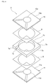
- Fig. 4 is an exploded perspective view of the ultrasonic wave generation element 6.
- the ultrasonic wave generation element 6 includes a frame body 7.
- the frame body 7 has a first main surface 7a, a second main surface 7b that is opposite to the first main surface 7a, and four side surfaces including a side surface 7e serving as a first side surface.
- the frame body 7 is formed from a ceramic material such as alumina, a synthetic resin such as glass epoxy, or the like, for example.
- a through-hole 7c that penetrates from the first main surface 7a toward the second main surface 7b is provided in a central area of the frame body 7.
- a ventilation hole 7d is provided in the frame body 7 spanning from the through-hole 7c to the side surface 7e. In the present embodiment, the ventilation hole 7d penetrates from the first main surface 7a toward the second main surface 7b.
- Fig. 5 is a plan view of the frame body 7. As illustrated in Fig. 5 , the ventilation hole 7d connects the through-hole 7c and the side surface 7e of the frame body 7 in a linear shape.
- a first piezoelectric vibrator 10 is bonded to the first main surface 7a of the frame body 7 with a frame-shaped adhesive layer 8 interposed therebetween so as to close off the through-hole 7c.
- a second piezoelectric vibrator 11 is bonded to the second main surface 7b of the frame body 7 with a frame-shaped adhesive layer 9 interposed therebetween so as to close off the through-hole 7c.
- the first and second piezoelectric vibrators 10 and 11 are bimorph-type piezoelectric vibrators having plate shapes.
- a part of the frame body 7 where the stated through-hole 7c is provided is sealed from above and below.
- the ultrasonic wave generation element 6 has an inner space formed by the through-hole 7c and the first and second piezoelectric vibrators 10 and 11.
- the stated ventilation hole 7d is provided in the frame body 7 in order to enable the inner space of the ultrasonic wave generation element 6 to communicate with the exterior.
- the ultrasonic wave generation element 6 can be prevented from being damaged.
- the first piezoelectric vibrator 10 has a rectangular plate-shaped piezoelectric plate 10a.
- the piezoelectric plate 10a has two piezoelectric material layers formed of piezoelectric ceramics such as PZT, and an inner electrode 10b disposed between the two piezoelectric material layers.
- An exciting electrode 10c is provided in a central area of a top surface of the piezoelectric plate 10a.
- the exciting electrode 10c is provided so as to overlap with the inner electrode 10b, with the upper-side piezoelectric material layer interposed therebetween.
- An exciting electrode 10d is provided in a central area of a bottom surface of the piezoelectric plate 10a.
- the exciting electrode 10d is provided so as to overlap with the inner electrode 10b, with the lower-side piezoelectric material layer interposed therebetween.
- the piezoelectric material layer between the exciting electrode 10c and the inner electrode 10b and the piezoelectric material layer between the inner electrode 10b and the exciting electrode 10d are polarized in the same direction relative to a thickness direction.
- the exciting electrodes 10c and 10d are formed of a metal such as Ag, Pd, or the like, and an alloy thereof.
- the second piezoelectric vibrator 11 has a rectangular plate-shaped piezoelectric plate 11a.
- the piezoelectric plate 11a has two piezoelectric material layers formed of piezoelectric ceramics such as PZT, and an inner electrode 11b disposed between the two piezoelectric material layers.
- An exciting electrode 11c is provided in a central area of a bottom surface of the piezoelectric plate 11a.
- the exciting electrode 11c is provided so as to overlap with the inner electrode 11b, with the lower-side piezoelectric material layer interposed therebetween.
- An exciting electrode 11d is provided in a central area of a top surface of the piezoelectric plate 11a.
- the exciting electrode 11d is provided so as to overlap with the inner electrode 11b, with the upper-side piezoelectric material layer interposed therebetween.
- the piezoelectric material layer between the exciting electrode 11c and the inner electrode 11b and the piezoelectric material layer between the inner electrode 11b and the exciting electrode 11d are polarized in the same direction relative to the thickness direction.
- the exciting electrodes 11c and 11d are formed of a metal such as Ag, Pd, or the like, and an alloy thereof. Note that the piezoelectric material layers of the second piezoelectric vibrator 11 are polarized in the opposite direction to the piezoelectric material layers of the first piezoelectric vibrator 10, in the thickness direction. Accordingly, the second piezoelectric vibrator 11 is configured to vibrate at a phase opposite to the phase of the first piezoelectric vibrator 10.
- the piezoelectric material layers are not limited thereto.
- the piezoelectric material layers may be formed from a non-leaded piezoelectric ceramic material such as a potassium sodium niobate-based ceramic material, an alkali niobate-based ceramic material, or the like.
- the stated first piezoelectric vibrator 10 and second piezoelectric vibrator 11 are driven so as to vibrate at opposite phases.
- the ultrasonic wave generation element 6 vibrates in a buckling tuning-fork vibration mode. This vibration generates ultrasonic waves upward and downward from the ultrasonic wave generation element 6.
- the generated ultrasonic waves propagate in the directions indicated by the broken line arrows in Fig. 2 , and are emitted to the exterior from the sonic wave emission openings 3a to 3d.
- a feature of the ultrasonic wave generation apparatus 1 according to the present embodiment is that the ventilation hole 7d and the connecting members 5 are in a specific positional relationship, and as a result, it is difficult for the durability of the apparatus to drop even though the ventilation hole 7d is provided. This will be described in detail with reference to Fig. 6 to Fig. 11 .
- Fig. 6 is a general perspective view illustrating a positional relationship between the ventilation hole 7d and the connecting members 5 in the ultrasonic wave generation apparatus 1.
- the ventilation hole 7d opens into the aforementioned side surface 7e of the frame body 7.
- the cap member 3, the first piezoelectric vibrator 10, and the conductive adhesive 12 are not illustrated in Fig. 6 .
- the ventilation hole 7d is provided in a region of the side surface 7e where a connecting member 5 is located therebelow. Accordingly, the part of the ventilation hole 7d that opens into the side surface 7e is supported by the connecting member 5 located therebelow.
- the vicinity of the part of the ventilation hole 7d that opens into the side surface 7e is an area that is susceptible to stress from impacts caused by drops of the frame body 7 and the like. Accordingly, depending on the position where the ventilation hole 7d is provided, there is a risk of cracks forming in the area in the vicinity of the part of the ventilation hole 7d that opens into the side surface 7e due to stress from impacts caused by drops or the like.
- the ventilation hole 7d when viewing the ultrasonic wave generation apparatus 1 in plan view, the ventilation hole 7d is provided in a region of the side surface 7e where a connecting member 5 is located therebelow. Accordingly, because the part of the ventilation hole 7d that opens into the side surface 7e is supported by the connecting member 5 located therebelow, a drop in durability can be prevented even when the ventilation hole 7d is provided.
- a lengthwise direction position along the horizontal axis in Fig. 7 represents the position, in the lengthwise direction of the side surface 7e of the frame body 7, of the part of the ventilation hole 7d that opens into the side surface 7e.
- the vertical axis in Fig. 7 represents the magnitude of the stress acting on the frame body 7. Note that a direction, in the side surface 7e, that is parallel to the first main surface 7a or the second main surface 7b is taken as the lengthwise direction.
- the lengthwise direction position along the horizontal axis in Fig. 7 refers to a distance from a center position of the side surface 7e in the lengthwise direction to a center position of the part of the ventilation hole 7d that opens into the side surface 7e in the lengthwise direction.
- Fig. 8 is a diagram illustrating a positional relationship between the ventilation hole 7d and connecting members 5 and 5 in the lengthwise direction of the side surface 7e of the frame body 7, according to the first working example.
- the first and second piezoelectric vibrators 10 and 11 are illustrated in a simplified manner.
- the lengthwise direction dimension of the stated side surface 7e was set at 2 mm. Meanwhile, the dimension, along the stated lengthwise direction, of the part of the ventilation hole 7d that opens into the side surface 7e was set at 0.1 mm.
- the center position, in the lengthwise direction, of the part of the ventilation hole 7d that opens into the side surface 7e is provided in a center position of the side surface 7e in the lengthwise direction. Accordingly, the first working example illustrated in Fig. 8 corresponds to a lengthwise direction position of 0 ⁇ m in Fig. 7 .
- a location that is furthest from the center of the stated lengthwise direction in the side surface 7e, which serves as the first side surface is taken as an outer side end portion 5a.
- a location that is closest to the center of the stated lengthwise direction in the side surface 7e is taken as an inner side end portion 5b.
- positions of the outer side end portion 5a in the connecting members 5 and 5 are not particularly limited, in the first working example, those positions are the same as the positions of the respective end portions of the side surface 7e in the lengthwise direction.
- Fig. 9 is a diagram illustrating a positional relationship between the ventilation hole 7d and the connecting members 5 and 5 in the lengthwise direction of the side surface 7e of the frame body 7, according to a comparative example.
- the comparative example differs from the first working example only in terms of the position of the part of the ventilation hole 7d that opens into the side surface 7e, which corresponds to a lengthwise direction position of 650 ⁇ m in Fig. 7 .
- Fig. 9 is a diagram illustrating a positional relationship between the ventilation hole 7d and the connecting members 5 and 5 in the lengthwise direction of the side surface 7e of the frame body 7, according to a comparative example.
- the comparative example differs from the first working example only in terms of the position of the part of the ventilation hole 7d that opens into the side surface 7e, which corresponds to a lengthwise direction position of 650 ⁇ m in Fig. 7 .
- Fig. 9 is a diagram illustrating a positional relationship between the ventilation hole 7d and the connecting members 5
- an outer side end portion 7d1 in the lengthwise direction, of the part of the ventilation hole 7d that opens into the side surface 7e matches the inner side end portion 5b, in the lengthwise direction, of the connecting member 5 located therebelow.
- the stress acting on the frame body 7 varies greatly as the stated lengthwise direction position varies. It can be seen that the stress acting on the frame body 7 is greatest, resulting in a drop in durability, in the case where the lengthwise direction position is 650 ⁇ m, or in other words, in the comparative example illustrated in Fig. 9 . Accordingly, when viewing the ultrasonic wave generation apparatus 1 in plan view, it is necessary for the outer side end portion 7d1 of the ventilation hole 7d to be in a position, in the side surface 7e, that does not overlap with the inner side end portion 5b of the connecting member 5. Through this, a drop in durability can be prevented even when the ventilation hole 7d is provided.
- the outer side end portion 7d1 of the ventilation hole 7d is in a position, in the side surface 7e, that does not overlap with the inner side end portion 5b of the connecting member 5; as such, a lower amount of stress acts on the frame body 7 and the durability does not drop as compared to the comparative example.
- the part of the ventilation hole 7d that opens into the side surface 7e is provided in a position, in the side surface 7e, that is different from a central area of the side surface 7e in the lengthwise direction, and thus does not overlap with the connecting member 5 located therebelow.
- the outer side end portion 7d1 in the lengthwise direction, of the part of the ventilation hole 7d that opens into the side surface 7e is in a position that does not overlap with the inner side end portion 5b, in the lengthwise direction, of the connecting member 5 located therebelow and a position further toward the center in the lengthwise direction than the inner side end portion 5b.
- the outer side end portion 7d1 of the ventilation hole 7d does not overlap with the inner side end portion 5b of the connecting member 5 in the side surface 7e; as such, a lower amount of stress acts on the frame body 7 and the durability does not drop as compared to the comparative example. Furthermore, a lower amount of stress acts on the frame body 7 and there is almost no drop in durability as compared to the first working example.
- Fig. 10 is a diagram illustrating a positional relationship between the ventilation hole 7d and connecting members 5 and 5 in the lengthwise direction of the side surface 7e of the frame body 7, according to a second working example.
- the second working example differs from the first working example only in terms of the position of the part of the ventilation hole 7d that opens into the side surface 7e, which corresponds to a lengthwise direction position of 700 ⁇ m in Fig. 7 .
- Fig. 10 is a diagram illustrating a positional relationship between the ventilation hole 7d and connecting members 5 and 5 in the lengthwise direction of the side surface 7e of the frame body 7, according to a second working example.
- the second working example differs from the first working example only in terms of the position of the part of the ventilation hole 7d that opens into the side surface 7e, which corresponds to a lengthwise direction position of 700 ⁇ m in Fig. 7 .
- Fig. 10 is a diagram illustrating a positional relationship between the ventilation hole 7d and connecting members 5 and 5 in the length
- the part of the ventilation hole 7d that opens into the side surface 7e is provided in a position that is different from a central area of the side surface 7e in the lengthwise direction, and partially overlaps with the connecting member 5 located therebelow.
- the outer side end portion 7d1 in the lengthwise direction, of the part of the ventilation hole 7d that opens into the side surface 7e does not overlap with the inner side end portion 5b, in the lengthwise direction, of the connecting member 5 located therebelow, and is in a position between the outer side end portion 5a and the inner side end portion 5b.
- the outer side end portion 7d1 of the ventilation hole 7d does not overlap with the inner side end portion 5b of the connecting member 5 in the side surface 7e; as such, a lower amount of stress acts on the frame body 7 as compared to the comparative example, as indicated in Fig. 7 . Accordingly, it can be seen that the durability does not drop.
- Fig. 11 is a diagram illustrating a positional relationship between the ventilation hole 7d and connecting members 5 and 5 in the lengthwise direction of the side surface 7e of the frame body 7, according to a third working example.
- the third working example differs from the first working example only in terms of the position of the part of the ventilation hole 7d that opens into the side surface 7e, which corresponds to a lengthwise direction position of 750 ⁇ m in Fig. 7 .
- the part of the ventilation hole 7d that opens into the side surface 7e is provided in a position that is different from a central area of the side surface 7e in the lengthwise direction.
- the ventilation hole 7d is provided so that the part of the ventilation hole 7d that opens into the side surface 7e is covered by the connecting member 5 located therebelow when viewed from below.
- the outer side end portion 7d1 in the lengthwise direction, of the part of the ventilation hole 7d that opens into the side surface 7e does not overlap with the inner side end portion 5b, in the lengthwise direction, of the connecting member 5 located therebelow, and is in a position between the outer side end portion 5a and the inner side end portion 5b.
- the part of the ventilation hole 7d that opens into the side surface 7e is provided in a region in a different position from the central area of the side surface 7e in the lengthwise direction and in a position where the connecting member 5 is located therebelow, as in the aforementioned embodiment; the outer side end portion 7d1 of the ventilation hole 7d does not overlap with the inner side end portion 5b of the connecting member 5, and thus the stress acting on the frame body 7 becomes extremely small and there is almost no drop in durability.
- the ventilation hole 7d is provided so as to penetrate from the first main surface 7a to the second main surface 7b of the frame body 7 as indicated in Fig. 4
- the shape of the ventilation hole is not particularly limited.
- the ventilation hole may be formed having a part that opens into the side surface 7e as a groove 7f whose horizontal cross-section is rectangular, with an opening only on the first main surface 7a side of the frame body 7, as illustrated in Fig. 12(a) .
- the ventilation hole may be formed having a part that opens into the side surface 7e as a hollow passage 7g, without having an opening in the first main surface 7a and the second main surface 7b of the frame body 7, as illustrated in Fig. 12(b) .
- the ventilation hole may be formed having a part that opens into the side surface 7e as a groove 7h whose horizontal cross-section is semicircular, a groove 7i whose horizontal cross-section is V-shaped, or the like, with an opening only on the first main surface 7a side of the frame body 7, as illustrated in Figs. 12(c) and (d) .
- resonance occurs within the ventilation hole 7d as well.
- a frequency of the resonance in the ventilation hole 7d matches a frequency of resonance, produced by sonic waves emitted due to the vibration of the first and second piezoelectric vibrators 10 and 11, that takes the sonic wave emission openings 3a to 3d as open ends, the resonances will interfere with each other within the housing, resulting in a drop in the sound pressure of the ultrasonic waves emitted from the ultrasonic wave generation apparatus.
- the frequency of the resonance in the ventilation hole 7d be different from the frequency of resonance, produced by sonic waves emitted due to the vibration of the first and second piezoelectric vibrators 10 and 11, that takes the sonic wave emission openings 3a to 3d as open ends.
- the frequency of the resonance is the frequency of a sound pressure peak.
- the stated first and second piezoelectric vibrators 10 and 11 are not limited to bimorph-type piezoelectric vibrators, and may be piezoelectric vibrators having other structures such as unimorph types.
- the stated ultrasonic wave generation element 6 and connecting members 5 are required constituent elements, and the package structure is not limited to that described in the aforementioned embodiment.
Landscapes
- Engineering & Computer Science (AREA)
- Mechanical Engineering (AREA)
- Physics & Mathematics (AREA)
- Acoustics & Sound (AREA)
- Multimedia (AREA)
- Transducers For Ultrasonic Waves (AREA)
- General Electrical Machinery Utilizing Piezoelectricity, Electrostriction Or Magnetostriction (AREA)
- Measurement Of Velocity Or Position Using Acoustic Or Ultrasonic Waves (AREA)
Abstract
Description
- The present invention relates to an ultrasonic wave generation apparatus in which plate-shaped first and second vibrators vibrate at opposite phases.
- Thus far, ultrasonic wave generation apparatuses have been used in rangefinding techniques and the like that employ ultrasonic waves.
- For example,
Patent Document 1, indicated below, discloses an ultrasonic wave generation apparatus that uses a piezoelectric vibrator. This ultrasonic wave generation apparatus includes a housing and an ultrasonic wave generation element disposed within the housing. The ultrasonic wave generation element has a frame body and plate-shaped first and second piezoelectric vibrators. A groove or a through-hole is formed in a central area of the frame body. To close off the groove or through-hole, the first piezoelectric vibrator is bonded to a first main surface of the frame body and the second piezoelectric vibrator is bonded to a second main surface that is opposite to the first main surface. The first piezoelectric vibrator and the second piezoelectric vibrator vibrate at opposite phases from each other, and as a result, the ultrasonic wave generation element vibrates in a buckling tuning-fork vibration mode. The ultrasonic wave generation apparatus disclosed inPatent Document 1 emits ultrasonic waves generated by the vibration of this ultrasonic wave generation element. - On the other hand,
Patent Document 2, indicated below, discloses an electroacoustic transducer that uses a support body having a hollow structure. In this electroacoustic transducer, a part of each of main surfaces of the support body is constituted by an elastic material. Piezoelectric elements are bonded to outer side portions of the parts of both main surfaces of the support body that are constituted by the elastic material. In addition, an acoustic emission opening is formed in a side surface of the support body. This acoustic emission opening is formed as a through-hole that makes an inner space of the support body communicate with the exterior. -
- Patent Document 1:
WO2012/026319 - Patent Document 2:
Japanese Unexamined Patent Application Publication No. 2011-228966 - In the ultrasonic wave generation apparatus disclosed in
Patent Document 1, the groove or through-hole of the frame body is closed off by the first and second piezoelectric vibrators. Accordingly, an inner space enclosed by the first and second piezoelectric vibrators and the frame body is sealed. As such, if the ultrasonic wave generation element is exposed to high temperatures during manufacture, such as when disposing the ultrasonic wave generation element within the housing, there is a risk that the ultrasonic wave generation element will be damaged due to the expansion of water vapor or the like within the inner space. To prevent such damage, providing a ventilation hole in the frame body to enable the inner space to communicate with the exterior is considered desirable. Specifically, providing a through-hole in a side surface of the frame body and using that through-hole as the ventilation hole can be considered. However, providing such a ventilation hole may lead to a drop in durability. For example, there is a risk of cracks being formed in the ultrasonic wave generation element or the like when stress acts thereon due to impacts from being dropped and so on. - Note that the acoustic emission opening in the electroacoustic transducer disclosed in
Patent Document 2 is provided to emit sound waves produced within the support body, and is not provided as a ventilation hole for enabling the inner space of the support body to communicate with the exterior as described above. - It is an object of the present invention to provide an ultrasonic wave generation apparatus in which a ventilation hole that enables an interior space of an ultrasonic wave generation element to communicate with the exterior is provided in a frame body, and that does not easily experience a drop in durability.
- An ultrasonic wave generation apparatus according to the present invention includes an ultrasonic wave generation element and a connecting member. The ultrasonic wave generation element has a frame body and plate-shaped first and second vibrators. The frame body has first and second main surfaces that are opposite to each other and a plurality of side surfaces. In the first and second main surfaces, one of a groove or a through-hole is provided in the first and second main surfaces. A plate-shaped first vibrator is bonded to the first main surface so as to close off the groove or the through-hole on the first main surface side of the frame body. A plate-shaped second vibrator is bonded to the second main surface so as to close off the groove or the through-hole on the second main surface side of the frame body. The ultrasonic wave generation element has an inner space formed by the groove or the through-hole and the first and second vibrators.
- The connecting member is bonded to a surface of the second vibrator opposite to the surface of the second vibrator that is bonded to the second main surface of the frame body. The connecting member supports the ultrasonic wave generation element, and is electrically connected to at least one of the first and second vibrators.
- In the present invention, a ventilation hole that has a part that opens into a first side surface of the plurality of side surfaces and that allows the inner space and an exterior to communicate is provided in the frame body. A direction of the first side surface that is parallel to the first main surface or the second main surface is taken as a lengthwise direction. In the first side surface, in the part of the ventilation hole that opens into the first side surface, a location furthest from a center of the first side surface in the lengthwise direction is taken as an outer side end portion. Meanwhile, a location closest to the center of the first side surface in the lengthwise direction is taken as an inner side end portion. The ventilation hole is provided so that, when viewed in plan view, the outer side end portion of the part of the ventilation hole that opens into the first side surface is in a position that does not overlap with the inner side end portion of the connecting member.
- According to a specific aspect of the ultrasonic wave generation apparatus according to the present invention, the ventilation hole is provided so that, when viewed in plan view, the outer side end portion of the part that opens into the first side surface is in a position that is different from the center of the first side surface in the lengthwise direction and that does not overlap with the inner side end portion of the connecting member. Through this, stress acting on the frame body becomes extremely small, and a drop in durability can be almost completely prevented.
- According to another specific aspect of the ultrasonic wave generation apparatus according to the present invention, the ventilation hole is provided so that the part that opens into the first side surface is covered by the connecting member when viewed from below. Through this, stress acting on the frame body becomes extremely small, and a drop in durability can be almost completely prevented.
- According to yet another specific aspect of the ultrasonic wave generation apparatus according to the present invention, the ultrasonic wave generation apparatus further includes a housing that houses the ultrasonic wave generation element and that has a sonic wave emission opening, and a frequency of a resonance within the ventilation hole is different from a frequency of resonance, produced by sonic waves emitted due to vibration of the first and second vibrators, that takes the sonic wave emission opening as an open end. Through this, a drop in the sound pressure of ultrasonic waves emitted from the ultrasonic wave generation apparatus can be reduced.
- According to still another specific aspect of the ultrasonic wave generation apparatus according to the present invention, the ultrasonic wave generation element generates ultrasonic waves in a buckling tuning-fork vibration mode in which the first vibrator and the second vibrator vibrate at opposite phases.
- In the ultrasonic wave generation apparatus according to the present invention, the ventilation hole that allows the inner space of the ultrasonic wave generation element to communicate with the exterior is provided in the frame body, and thus the ultrasonic wave generation element can be prevented from being damaged even if the ultrasonic wave generation element is exposed to high temperatures and water vapor or the like within the inner space has expanded. Furthermore, because the ventilation hole is provided so as to be in a specific positional relationship with the connecting member, cracks will not form in the ultrasonic wave generation element even when stress caused by a drop impact or the like acts thereon. Accordingly, a drop in the durability of an ultrasonic wave generation apparatus having a ventilation hole can be prevented.
-
- [
Fig. 1] Fig. 1 is a perspective view illustrating the external appearance of an ultrasonic wave generation apparatus according to an embodiment of the present invention. - [
Fig. 2] Fig. 2 is a cross-sectional view of an ultrasonic wave generation apparatus according to an embodiment of the present invention, taken along an X-X line indicated inFig. 1 . - [
Fig. 3] Fig. 3 is an exploded perspective view of an ultrasonic wave generation apparatus according to an embodiment of the present invention. - [
Fig. 4] Fig. 4 is an exploded perspective view of an ultrasonic wave generation element included in an ultrasonic wave generation apparatus according to an embodiment of the present invention. - [
Fig. 5] Fig. 5 is a plan view of a frame body included in an ultrasonic wave generation apparatus according to an embodiment of the present invention. - [
Fig. 6] Fig. 6 is a general perspective view illustrating a positional relationship between a ventilation hole and a connecting member in an ultrasonic wave generation apparatus according to an embodiment of the present invention. - [
Fig. 7] Fig. 7 is a diagram illustrating a relationship between a position of a ventilation hole in a lengthwise direction of a first side surface of a frame body and stress acting thereon during a drop impact. - [
Fig. 8] Fig. 8 is a side view illustrating a positional relationship between a ventilation hole and connecting members in a lengthwise direction of a first side surface of a frame body according to a first working example of the present invention. - [
Fig. 9] Fig. 9 is a side view illustrating a positional relationship between a ventilation hole and connecting members in a lengthwise direction of a first side surface of a frame body according to a comparative example. - [
Fig. 10] Fig. 10 is a side view illustrating a positional relationship between a ventilation hole and connecting members in a lengthwise direction of a first side surface of a frame body according to a second working example of the present invention. - [
Fig. 11] Fig. 11 is a side view illustrating a positional relationship between a ventilation hole and connecting members in a lengthwise direction of a first side surface of a frame body according to a third working example of the present invention. - [
Fig. 12] Fig. 12(a) to Fig. 12(d) are each side views for illustrating variations on a shape of a ventilation hole in an ultrasonic wave generation apparatus according to the present invention. - The present invention will be made clear hereinafter through descriptions of a specific embodiment of the present invention with reference to the drawings.
-
Fig. 1 is a perspective view illustrating the external appearance of an ultrasonicwave generation apparatus 1 according to an embodiment of the present invention.Fig. 2 is a cross-sectional view of the ultrasonicwave generation apparatus 1, taken along an X-X line indicated inFig. 1 .Fig. 3 is an exploded perspective view of the ultrasonicwave generation apparatus 1. - The ultrasonic
wave generation apparatus 1 includes a plate-shapedbase board 2 and acap member 3 having an opening that opens downward. - As illustrated in
Fig. 1 and Fig. 2 , thecap member 3 is fixed upon thebase board 2, and a housing is formed by thebase board 2 and thecap member 3. An ultrasonicwave generation element 6, which will be mentioned later, is housed within a space enclosed by thebase board 2 and thecap member 3, or in other words, within the housing. Thebase board 2 is a ceramic board constituted by alumina, a glass epoxy board, or the like, for example. - As illustrated in
Fig. 1 , a plurality of sonicwave emission openings 3a to 3d are provided in a top surface of thecap member 3. - As illustrated in
Fig. 3 , a plurality ofelectrode lands 4 are provided on atop surface 2a of the statedbase board 2. The electrode lands 4 are electrically connected to terminal electrodes (not shown) provided in a bottom surface of thebase board 2 by through-hole electrodes or the like provided in thebase board 2. The ultrasonicwave generation element 6 is mechanically bonded to the plurality ofelectrode lands 4 with a plurality of connectingmembers 5 interposed therebetween, and is also electrically connected thereto. As mentioned above, the connectingmembers 5 have a function of mechanically supporting the ultrasonicwave generation element 6 on thebase board 2 and a function of electrically connecting the ultrasonicwave generation element 6 to the terminal electrodes (not shown). - To provide a gap between the
top surface 2a of thebase board 2 and a lower surface of the ultrasonicwave generation element 6, it is necessary for the connectingmembers 5 to have a certain degree of thickness, as illustrated inFig. 2 . The connectingmembers 5 are formed from a metal material, for example. Ultimately, a material aside from metal, such as a conductive resin material or the like, may be employed as well, as long as the connectingmembers 5 have the function of mechanically supporting the ultrasonicwave generation element 6 on thebase board 2 and the function of electrically connecting the ultrasonicwave generation element 6 to the terminal electrodes (not shown). In the present embodiment, the connectingmembers 5 are formed from a metal material, and the connectingmembers 5 and the ultrasonicwave generation element 6 are bonded by aconductive adhesive 12. Note that the connectingmembers 5 and the ultrasonicwave generation element 6 may be bonded using solder instead of theconductive adhesive 12. Alternatively, the connectingmembers 5 may be formed of a material having adhesive properties, such as an epoxy resin-based conductive adhesive or the like. - The ultrasonic
wave generation element 6 will be described in detail with reference toFig. 2 andFig. 4. Fig. 4 is an exploded perspective view of the ultrasonicwave generation element 6. - The ultrasonic
wave generation element 6 includes aframe body 7. Theframe body 7 has a firstmain surface 7a, a secondmain surface 7b that is opposite to the firstmain surface 7a, and four side surfaces including aside surface 7e serving as a first side surface. Theframe body 7 is formed from a ceramic material such as alumina, a synthetic resin such as glass epoxy, or the like, for example. A through-hole 7c that penetrates from the firstmain surface 7a toward the secondmain surface 7b is provided in a central area of theframe body 7. Aventilation hole 7d is provided in theframe body 7 spanning from the through-hole 7c to theside surface 7e. In the present embodiment, theventilation hole 7d penetrates from the firstmain surface 7a toward the secondmain surface 7b. -
Fig. 5 is a plan view of theframe body 7. As illustrated inFig. 5 , theventilation hole 7d connects the through-hole 7c and theside surface 7e of theframe body 7 in a linear shape. - A first
piezoelectric vibrator 10 is bonded to the firstmain surface 7a of theframe body 7 with a frame-shapedadhesive layer 8 interposed therebetween so as to close off the through-hole 7c. A secondpiezoelectric vibrator 11 is bonded to the secondmain surface 7b of theframe body 7 with a frame-shapedadhesive layer 9 interposed therebetween so as to close off the through-hole 7c. - The first and second
piezoelectric vibrators piezoelectric vibrators main surfaces frame body 7, respectively, a part of theframe body 7 where the stated through-hole 7c is provided is sealed from above and below. Accordingly, the ultrasonicwave generation element 6 has an inner space formed by the through-hole 7c and the first and secondpiezoelectric vibrators ventilation hole 7d is provided in theframe body 7 in order to enable the inner space of the ultrasonicwave generation element 6 to communicate with the exterior. Through this, even if the ultrasonicwave generation element 6 is exposed to high temperatures during manufacture, such as when mounting the ultrasonicwave generation element 6 on thebase board 2, and water vapor or the like within the inner space has expanded as a result, the ultrasonicwave generation element 6 can be prevented from being damaged. - The first
piezoelectric vibrator 10 has a rectangular plate-shapedpiezoelectric plate 10a. Thepiezoelectric plate 10a has two piezoelectric material layers formed of piezoelectric ceramics such as PZT, and aninner electrode 10b disposed between the two piezoelectric material layers. Anexciting electrode 10c is provided in a central area of a top surface of thepiezoelectric plate 10a. Theexciting electrode 10c is provided so as to overlap with theinner electrode 10b, with the upper-side piezoelectric material layer interposed therebetween. Anexciting electrode 10d is provided in a central area of a bottom surface of thepiezoelectric plate 10a. Theexciting electrode 10d is provided so as to overlap with theinner electrode 10b, with the lower-side piezoelectric material layer interposed therebetween. The piezoelectric material layer between theexciting electrode 10c and theinner electrode 10b and the piezoelectric material layer between theinner electrode 10b and theexciting electrode 10d are polarized in the same direction relative to a thickness direction. Theexciting electrodes - The second
piezoelectric vibrator 11 has a rectangular plate-shapedpiezoelectric plate 11a. Thepiezoelectric plate 11a has two piezoelectric material layers formed of piezoelectric ceramics such as PZT, and aninner electrode 11b disposed between the two piezoelectric material layers. Anexciting electrode 11c is provided in a central area of a bottom surface of thepiezoelectric plate 11a. Theexciting electrode 11c is provided so as to overlap with theinner electrode 11b, with the lower-side piezoelectric material layer interposed therebetween. Anexciting electrode 11d is provided in a central area of a top surface of thepiezoelectric plate 11a. Theexciting electrode 11d is provided so as to overlap with theinner electrode 11b, with the upper-side piezoelectric material layer interposed therebetween. The piezoelectric material layer between theexciting electrode 11c and theinner electrode 11b and the piezoelectric material layer between theinner electrode 11b and theexciting electrode 11d are polarized in the same direction relative to the thickness direction. Theexciting electrodes piezoelectric vibrator 11 are polarized in the opposite direction to the piezoelectric material layers of the firstpiezoelectric vibrator 10, in the thickness direction. Accordingly, the secondpiezoelectric vibrator 11 is configured to vibrate at a phase opposite to the phase of the firstpiezoelectric vibrator 10. - Although the foregoing describes the piezoelectric material layers as being formed from PZT-based ceramic material, the piezoelectric material layers are not limited thereto. The piezoelectric material layers may be formed from a non-leaded piezoelectric ceramic material such as a potassium sodium niobate-based ceramic material, an alkali niobate-based ceramic material, or the like.
- In the ultrasonic
wave generation element 6, the stated firstpiezoelectric vibrator 10 and secondpiezoelectric vibrator 11 are driven so as to vibrate at opposite phases. As a result, the ultrasonicwave generation element 6 vibrates in a buckling tuning-fork vibration mode. This vibration generates ultrasonic waves upward and downward from the ultrasonicwave generation element 6. The generated ultrasonic waves propagate in the directions indicated by the broken line arrows inFig. 2 , and are emitted to the exterior from the sonicwave emission openings 3a to 3d. - A feature of the ultrasonic
wave generation apparatus 1 according to the present embodiment is that theventilation hole 7d and the connectingmembers 5 are in a specific positional relationship, and as a result, it is difficult for the durability of the apparatus to drop even though theventilation hole 7d is provided. This will be described in detail with reference toFig. 6 to Fig. 11 . -
Fig. 6 is a general perspective view illustrating a positional relationship between theventilation hole 7d and the connectingmembers 5 in the ultrasonicwave generation apparatus 1. As illustrated inFig. 6 , theventilation hole 7d opens into theaforementioned side surface 7e of theframe body 7. Thecap member 3, the firstpiezoelectric vibrator 10, and the conductive adhesive 12 are not illustrated inFig. 6 . When viewing the ultrasonicwave generation apparatus 1 in plan view, theventilation hole 7d is provided in a region of theside surface 7e where a connectingmember 5 is located therebelow. Accordingly, the part of theventilation hole 7d that opens into theside surface 7e is supported by the connectingmember 5 located therebelow. - The vicinity of the part of the
ventilation hole 7d that opens into theside surface 7e is an area that is susceptible to stress from impacts caused by drops of theframe body 7 and the like. Accordingly, depending on the position where theventilation hole 7d is provided, there is a risk of cracks forming in the area in the vicinity of the part of theventilation hole 7d that opens into theside surface 7e due to stress from impacts caused by drops or the like. - As opposed to this, according to the present embodiment, when viewing the ultrasonic
wave generation apparatus 1 in plan view, theventilation hole 7d is provided in a region of theside surface 7e where a connectingmember 5 is located therebelow. Accordingly, because the part of theventilation hole 7d that opens into theside surface 7e is supported by the connectingmember 5 located therebelow, a drop in durability can be prevented even when theventilation hole 7d is provided. - The inventors of the present invention examined a relationship between the position where the
ventilation hole 7d opens into theside surface 7e and stress acting on theframe body 7 by an impact caused by a drop. The results are illustrated inFig. 7 . A lengthwise direction position along the horizontal axis inFig. 7 represents the position, in the lengthwise direction of theside surface 7e of theframe body 7, of the part of theventilation hole 7d that opens into theside surface 7e. The vertical axis inFig. 7 represents the magnitude of the stress acting on theframe body 7. Note that a direction, in theside surface 7e, that is parallel to the firstmain surface 7a or the secondmain surface 7b is taken as the lengthwise direction. The lengthwise direction position along the horizontal axis inFig. 7 refers to a distance from a center position of theside surface 7e in the lengthwise direction to a center position of the part of theventilation hole 7d that opens into theside surface 7e in the lengthwise direction. - The stated lengthwise direction position will be described using a first working example, illustrated in
Fig. 8 , as an example.Fig. 8 is a diagram illustrating a positional relationship between theventilation hole 7d and connectingmembers side surface 7e of theframe body 7, according to the first working example. InFig. 8 , the first and secondpiezoelectric vibrators - The lengthwise direction dimension of the stated
side surface 7e was set at 2 mm. Meanwhile, the dimension, along the stated lengthwise direction, of the part of theventilation hole 7d that opens into theside surface 7e was set at 0.1 mm. InFig. 8 , the center position, in the lengthwise direction, of the part of theventilation hole 7d that opens into theside surface 7e is provided in a center position of theside surface 7e in the lengthwise direction. Accordingly, the first working example illustrated inFig. 8 corresponds to a lengthwise direction position of 0 µm inFig. 7 . - Note that with respect to the part of the
ventilation hole 7d that opens into theside surface 7e, a location that is furthest from the center of the stated lengthwise direction in theside surface 7e, which serves as the first side surface, is taken as an outerside end portion 5a. On the other hand, a location that is closest to the center of the stated lengthwise direction in theside surface 7e is taken as an innerside end portion 5b. - Although the positions of the outer
side end portion 5a in the connectingmembers side surface 7e in the lengthwise direction. -
Fig. 9 is a diagram illustrating a positional relationship between theventilation hole 7d and the connectingmembers side surface 7e of theframe body 7, according to a comparative example. The comparative example differs from the first working example only in terms of the position of the part of theventilation hole 7d that opens into theside surface 7e, which corresponds to a lengthwise direction position of 650 µm inFig. 7 . As illustrated inFig. 9 , in the comparative example, when viewing the ultrasonic wave generation apparatus in plan view, in theside surface 7e, an outer side end portion 7d1, in the lengthwise direction, of the part of theventilation hole 7d that opens into theside surface 7e matches the innerside end portion 5b, in the lengthwise direction, of the connectingmember 5 located therebelow. - As is clear from
Fig. 7 , the stress acting on theframe body 7 varies greatly as the stated lengthwise direction position varies. It can be seen that the stress acting on theframe body 7 is greatest, resulting in a drop in durability, in the case where the lengthwise direction position is 650 µm, or in other words, in the comparative example illustrated inFig. 9 . Accordingly, when viewing the ultrasonicwave generation apparatus 1 in plan view, it is necessary for the outer side end portion 7d1 of theventilation hole 7d to be in a position, in theside surface 7e, that does not overlap with the innerside end portion 5b of the connectingmember 5. Through this, a drop in durability can be prevented even when theventilation hole 7d is provided. - On the other hand, in the first working example that corresponds to a case where the lengthwise direction position is 0 µm, when viewing the ultrasonic
wave generation apparatus 1 in plan view, the outer side end portion 7d1 of theventilation hole 7d is in a position, in theside surface 7e, that does not overlap with the innerside end portion 5b of the connectingmember 5; as such, a lower amount of stress acts on theframe body 7 and the durability does not drop as compared to the comparative example. - Meanwhile, in the case where the lengthwise direction position is 400 µm, when viewing the ultrasonic
wave generation apparatus 1 in plan view, the part of theventilation hole 7d that opens into theside surface 7e is provided in a position, in theside surface 7e, that is different from a central area of theside surface 7e in the lengthwise direction, and thus does not overlap with the connectingmember 5 located therebelow. To rephrase, in the case where the lengthwise direction position is 400 µm, when viewing the ultrasonicwave generation apparatus 1 in plan view, in theside surface 7e, the outer side end portion 7d1, in the lengthwise direction, of the part of theventilation hole 7d that opens into theside surface 7e is in a position that does not overlap with the innerside end portion 5b, in the lengthwise direction, of the connectingmember 5 located therebelow and a position further toward the center in the lengthwise direction than the innerside end portion 5b. As is clear fromFig. 7 , in the case where the lengthwise direction position is 400 µm, when viewing the ultrasonicwave generation apparatus 1 in plan view, the outer side end portion 7d1 of theventilation hole 7d does not overlap with the innerside end portion 5b of the connectingmember 5 in theside surface 7e; as such, a lower amount of stress acts on theframe body 7 and the durability does not drop as compared to the comparative example. Furthermore, a lower amount of stress acts on theframe body 7 and there is almost no drop in durability as compared to the first working example. -
Fig. 10 is a diagram illustrating a positional relationship between theventilation hole 7d and connectingmembers side surface 7e of theframe body 7, according to a second working example. The second working example differs from the first working example only in terms of the position of the part of theventilation hole 7d that opens into theside surface 7e, which corresponds to a lengthwise direction position of 700 µm inFig. 7 . As illustrated inFig. 10 , in the second working example, when viewing the ultrasonicwave generation apparatus 1 in plan view, in theside surface 7e, the part of theventilation hole 7d that opens into theside surface 7e is provided in a position that is different from a central area of theside surface 7e in the lengthwise direction, and partially overlaps with the connectingmember 5 located therebelow. To rephrase, in the second working example, when viewing the ultrasonicwave generation apparatus 1 in plan view, in theside surface 7e, the outer side end portion 7d1, in the lengthwise direction, of the part of theventilation hole 7d that opens into theside surface 7e does not overlap with the innerside end portion 5b, in the lengthwise direction, of the connectingmember 5 located therebelow, and is in a position between the outerside end portion 5a and the innerside end portion 5b. - In the second working example that corresponds to a case where the lengthwise direction position is 700 µm, when viewing the ultrasonic
wave generation apparatus 1 in plan view, the outer side end portion 7d1 of theventilation hole 7d does not overlap with the innerside end portion 5b of the connectingmember 5 in theside surface 7e; as such, a lower amount of stress acts on theframe body 7 as compared to the comparative example, as indicated inFig. 7 . Accordingly, it can be seen that the durability does not drop. -
Fig. 11 is a diagram illustrating a positional relationship between theventilation hole 7d and connectingmembers side surface 7e of theframe body 7, according to a third working example. The third working example differs from the first working example only in terms of the position of the part of theventilation hole 7d that opens into theside surface 7e, which corresponds to a lengthwise direction position of 750 µm inFig. 7 . As illustrated inFig. 11 , in the third working example, when viewing the ultrasonicwave generation apparatus 1 in plan view, in theside surface 7e, the part of theventilation hole 7d that opens into theside surface 7e is provided in a position that is different from a central area of theside surface 7e in the lengthwise direction. To be more specific, theventilation hole 7d is provided so that the part of theventilation hole 7d that opens into theside surface 7e is covered by the connectingmember 5 located therebelow when viewed from below. To rephrase, in the third working example, when viewing the ultrasonicwave generation apparatus 1 in plan view, in theside surface 7e, the outer side end portion 7d1, in the lengthwise direction, of the part of theventilation hole 7d that opens into theside surface 7e does not overlap with the innerside end portion 5b, in the lengthwise direction, of the connectingmember 5 located therebelow, and is in a position between the outerside end portion 5a and the innerside end portion 5b. - As is clear from
Fig. 7 , in the third working example that corresponds to a case where the lengthwise direction position is 750 µm, when viewing the ultrasonicwave generation apparatus 1 in plan view, in theside surface 7e, the part of theventilation hole 7d that opens into theside surface 7e is provided in a region in a different position from the central area of theside surface 7e in the lengthwise direction and in a position where the connectingmember 5 is located therebelow, as in the aforementioned embodiment; the outer side end portion 7d1 of theventilation hole 7d does not overlap with the innerside end portion 5b of the connectingmember 5, and thus the stress acting on theframe body 7 becomes extremely small and there is almost no drop in durability. - As described above, by setting the lengthwise direction position of the
ventilation hole 7d to the aforementioned specific relationship, a drop in durability can be suppressed with certainty as compared to the comparative example illustrated inFig. 9 . - Although in the aforementioned embodiment, the
ventilation hole 7d is provided so as to penetrate from the firstmain surface 7a to the secondmain surface 7b of theframe body 7 as indicated inFig. 4 , the shape of the ventilation hole is not particularly limited. For example, the ventilation hole may be formed having a part that opens into theside surface 7e as agroove 7f whose horizontal cross-section is rectangular, with an opening only on the firstmain surface 7a side of theframe body 7, as illustrated inFig. 12(a) . Furthermore, the ventilation hole may be formed having a part that opens into theside surface 7e as ahollow passage 7g, without having an opening in the firstmain surface 7a and the secondmain surface 7b of theframe body 7, as illustrated inFig. 12(b) . Further still, the ventilation hole may be formed having a part that opens into theside surface 7e as agroove 7h whose horizontal cross-section is semicircular, agroove 7i whose horizontal cross-section is V-shaped, or the like, with an opening only on the firstmain surface 7a side of theframe body 7, as illustrated inFigs. 12(c) and (d) . - In addition, in the ultrasonic wave generation apparatus according to the present invention, resonance occurs within the
ventilation hole 7d as well. In the case where a frequency of the resonance in theventilation hole 7d matches a frequency of resonance, produced by sonic waves emitted due to the vibration of the first and secondpiezoelectric vibrators wave emission openings 3a to 3d as open ends, the resonances will interfere with each other within the housing, resulting in a drop in the sound pressure of the ultrasonic waves emitted from the ultrasonic wave generation apparatus. Accordingly, it is preferable that the frequency of the resonance in theventilation hole 7d be different from the frequency of resonance, produced by sonic waves emitted due to the vibration of the first and secondpiezoelectric vibrators wave emission openings 3a to 3d as open ends. As a result, a drop in the sound pressure of the ultrasonic waves emitted from the ultrasonic wave generation apparatus caused by resonance within theventilation hole 7d can be reduced. Note that the frequency of the resonance is the frequency of a sound pressure peak. - In the present invention, to provide the characteristic positional relationship for the ventilation hole provided in the frame body as described above, the stated first and second
piezoelectric vibrators - In addition, in the present invention, the stated ultrasonic
wave generation element 6 and connectingmembers 5 are required constituent elements, and the package structure is not limited to that described in the aforementioned embodiment. -
- 1... ultrasonic wave generation apparatus
- 2... base board
- 2a... top surface
- 3... cap member
- 3a to 3d... sonic wave emission opening
- 4... electrode land
- 5... connecting member
- 5a... outer side end portion
- 5b... inner side end portion
- 6... ultrasonic wave generation element
- 7... frame body
- 7a, 7b... first and second main surfaces
- 7c... through-hole
- 7d... ventilation hole
- 7d1... outer side end portion
- 7e... side surface
- 7f... groove
- 7g... hollow passage
- 7h... groove
- 7i... groove
- 8, 9... adhesive layer
- 10, 11... first and second piezoelectric vibrators
- 10a, 11a... piezoelectric plate
- 10b, 11b... inner electrode
- 10c, 10d, 11c, 11d... exciting electrode
- 12... conductive adhesive
Claims (5)
- An ultrasonic wave generation apparatus comprising:an ultrasonic wave generation element including a frame body having first and second main surfaces that are opposite to each other and a plurality of side surfaces as well as one of a groove or a through-hole provided in the first and second main surfaces, a plate-shaped first vibrator bonded to the first main surface so as to close off the groove or the through-hole on the first main surface side of the frame body, and a plate-shaped second vibrator bonded to the second main surface so as to close off the groove or the through-hole on the second main surface side of the frame body, the ultrasonic wave generation element having an inner space formed by the groove or the through-hole and the first and second vibrators; anda connecting member that is bonded to a surface of the second vibrator opposite to the surface of the second vibrator that is bonded to the second main surface of the frame body and that supports the ultrasonic wave generation element, and that is electrically connected to at least one of the first and second vibrators,wherein a ventilation hole that has a part that opens into a first side surface of the plurality of side surfaces and that allows the inner space and an exterior to communicate is provided in the frame body; andwhen a direction of the first side surface that is parallel to the first main surface or the second main surface is taken as a lengthwise direction, and in the part of the ventilation hole that opens into the first side surface, a location furthest from a center of the first side surface in the lengthwise direction is taken as an outer side end portion and a location closest to the center of the first side surface in the lengthwise direction is taken as an inner side end portion, the ventilation hole is provided so that, when viewed in plan view, the outer side end portion of the part of the ventilation hole that opens into the first side surface is in a position that does not overlap with the inner side end portion of the connecting member.
- The ultrasonic wave generation apparatus according to claim 1,
wherein the ventilation hole is provided so that, when viewed in plan view, the outer side end portion of the part that opens into the first side surface is in a position that is different from the center of the first side surface in the lengthwise direction and that does not overlap with the inner side end portion of the connecting member. - The ultrasonic wave generation apparatus according to claim 1,
wherein the ventilation hole is provided so that the part that opens into the first side surface is covered by the connecting member when viewed from below. - The ultrasonic wave generation apparatus according to any one of claims 1 to 3, further comprising:a housing that houses the ultrasonic wave generation element and that has a sonic wave emission opening,wherein a frequency of a resonance within the ventilation hole is different from a frequency of resonance, produced by sonic waves emitted due to vibration of the first and second vibrators, that takes the sonic wave emission opening as an open end.
- The ultrasonic wave generation apparatus according to any one of claims 1 to 4,
wherein the ultrasonic wave generation element generates ultrasonic waves in a buckling tuning-fork vibration mode in which the first vibrator and the second vibrator vibrate at opposite phases.
Applications Claiming Priority (2)
| Application Number | Priority Date | Filing Date | Title |
|---|---|---|---|
| JP2013091269 | 2013-04-24 | ||
| PCT/JP2013/085194 WO2014174729A1 (en) | 2013-04-24 | 2013-12-27 | Ultrasound emission device |
Publications (2)
| Publication Number | Publication Date |
|---|---|
| EP2991374A1 true EP2991374A1 (en) | 2016-03-02 |
| EP2991374A4 EP2991374A4 (en) | 2016-08-24 |
Family
ID=51791320
Family Applications (1)
| Application Number | Title | Priority Date | Filing Date |
|---|---|---|---|
| EP13883272.0A Withdrawn EP2991374A4 (en) | 2013-04-24 | 2013-12-27 | ULTRASOUND EMISSION DEVICE |
Country Status (5)
| Country | Link |
|---|---|
| US (1) | US10074352B2 (en) |
| EP (1) | EP2991374A4 (en) |
| JP (1) | JPWO2014174729A1 (en) |
| CN (1) | CN105144749A (en) |
| WO (1) | WO2014174729A1 (en) |
Families Citing this family (9)
| Publication number | Priority date | Publication date | Assignee | Title |
|---|---|---|---|---|
| WO2016104414A1 (en) * | 2014-12-26 | 2016-06-30 | 株式会社村田製作所 | Ultrasonic generation element and ultrasonic generation device provided with same |
| DE102015216163A1 (en) * | 2015-08-25 | 2017-03-02 | Robert Bosch Gmbh | Acoustic sensor for emitting and / or receiving acoustic signals |
| DE102016200657A1 (en) * | 2016-01-20 | 2017-07-20 | Robert Bosch Gmbh | Transducer array |
| JP7298225B2 (en) | 2019-03-20 | 2023-06-27 | セイコーエプソン株式会社 | MEMS devices and electronic equipment |
| WO2021186860A1 (en) * | 2020-03-18 | 2021-09-23 | 株式会社村田製作所 | Actuator, fluid control device, and actuator manufacturing method |
| CN113573216B (en) * | 2020-04-29 | 2023-11-03 | 维沃移动通信有限公司 | Speakers and electronic equipment |
| US12150384B2 (en) * | 2021-07-12 | 2024-11-19 | Robert Bosch Gmbh | Ultrasound transducer with distributed cantilevers |
| US12256642B2 (en) | 2021-07-12 | 2025-03-18 | Robert Bosch Gmbh | Ultrasound transducer with distributed cantilevers |
| US11899143B2 (en) | 2021-07-12 | 2024-02-13 | Robert Bosch Gmbh | Ultrasound sensor array for parking assist systems |
Family Cites Families (9)
| Publication number | Priority date | Publication date | Assignee | Title |
|---|---|---|---|---|
| JPS60134700A (en) * | 1983-12-23 | 1985-07-17 | Nippon Denso Co Ltd | Sound producing device |
| JPH0446798U (en) * | 1990-08-28 | 1992-04-21 | ||
| JP2894276B2 (en) * | 1996-05-02 | 1999-05-24 | 日本電気株式会社 | Piezo acoustic transducer |
| DE60332817D1 (en) * | 2002-03-15 | 2010-07-15 | Panasonic Corp | REFORMING DEVICE AND OPERATING METHOD THEREFOR |
| JP4513596B2 (en) * | 2004-08-25 | 2010-07-28 | 株式会社デンソー | Ultrasonic sensor |
| JP5088526B2 (en) * | 2005-04-18 | 2012-12-05 | ソニー株式会社 | Jet generator and electronic device |
| JP5652813B2 (en) * | 2010-04-21 | 2015-01-14 | レノボ・イノベーションズ・リミテッド(香港) | Electroacoustic transducer and electronic device using the same |
| JP5556893B2 (en) * | 2010-08-24 | 2014-07-23 | 株式会社村田製作所 | Ultrasonic generator |
| WO2013051400A1 (en) * | 2011-10-03 | 2013-04-11 | 株式会社村田製作所 | Ultrasonic-wave generation device |
-
2013
- 2013-12-27 JP JP2015513490A patent/JPWO2014174729A1/en active Pending
- 2013-12-27 EP EP13883272.0A patent/EP2991374A4/en not_active Withdrawn
- 2013-12-27 CN CN201380075796.0A patent/CN105144749A/en active Pending
- 2013-12-27 WO PCT/JP2013/085194 patent/WO2014174729A1/en not_active Ceased
-
2015
- 2015-10-01 US US14/873,076 patent/US10074352B2/en active Active
Also Published As
| Publication number | Publication date |
|---|---|
| US20160027424A1 (en) | 2016-01-28 |
| JPWO2014174729A1 (en) | 2017-02-23 |
| WO2014174729A1 (en) | 2014-10-30 |
| EP2991374A4 (en) | 2016-08-24 |
| CN105144749A (en) | 2015-12-09 |
| US10074352B2 (en) | 2018-09-11 |
Similar Documents
| Publication | Publication Date | Title |
|---|---|---|
| US10074352B2 (en) | Ultrasonic wave generation apparatus | |
| JP6135088B2 (en) | Ultrasonic transducer device, probe head, ultrasonic probe, electronic device and ultrasonic diagnostic apparatus | |
| US12275040B2 (en) | Piezoelectric device and ultrasonic transducer | |
| CN103858442B (en) | Ultrasonic generator | |
| TWI571134B (en) | Apparatus for generating sound | |
| JP5556893B2 (en) | Ultrasonic generator | |
| KR101518987B1 (en) | Acoustic generator, acoustic generation device, and electronic device | |
| WO2020230358A1 (en) | Piezoelectric device and acoustic transducer | |
| WO2016080387A1 (en) | Sound generating device and electronic equipment | |
| TWI590668B (en) | Sound generator, sound generator and electronic equipment | |
| WO2023095829A1 (en) | Ultrasonic transducer | |
| JP7088099B2 (en) | Ultrasonic sensor | |
| JP2003058166A (en) | Piezoelectric type electroacoustic transducer | |
| EP2819434B1 (en) | Ultrasonic wave-generating device | |
| JP6107940B2 (en) | Ultrasonic generator | |
| WO2014174731A1 (en) | Ultrasound generation device | |
| JP2014239333A (en) | Ultrasonic generator | |
| WO2023203879A1 (en) | Ultrasonic transducer and method for producing same | |
| WO2020250497A1 (en) | Piezoelectric device |
Legal Events
| Date | Code | Title | Description |
|---|---|---|---|
| PUAI | Public reference made under article 153(3) epc to a published international application that has entered the european phase |
Free format text: ORIGINAL CODE: 0009012 |
|
| 17P | Request for examination filed |
Effective date: 20151006 |
|
| AK | Designated contracting states |
Kind code of ref document: A1 Designated state(s): AL AT BE BG CH CY CZ DE DK EE ES FI FR GB GR HR HU IE IS IT LI LT LU LV MC MK MT NL NO PL PT RO RS SE SI SK SM TR |
|
| AX | Request for extension of the european patent |
Extension state: BA ME |
|
| DAX | Request for extension of the european patent (deleted) | ||
| A4 | Supplementary search report drawn up and despatched |
Effective date: 20160727 |
|
| RIC1 | Information provided on ipc code assigned before grant |
Ipc: H04R 17/00 20060101AFI20160721BHEP Ipc: G01S 7/521 20060101ALI20160721BHEP Ipc: B06B 1/06 20060101ALI20160721BHEP |
|
| STAA | Information on the status of an ep patent application or granted ep patent |
Free format text: STATUS: THE APPLICATION HAS BEEN WITHDRAWN |
|
| 18W | Application withdrawn |
Effective date: 20170721 |