EP2991050A1 - Secure enclosure - Google Patents
Secure enclosure Download PDFInfo
- Publication number
- EP2991050A1 EP2991050A1 EP15181361.5A EP15181361A EP2991050A1 EP 2991050 A1 EP2991050 A1 EP 2991050A1 EP 15181361 A EP15181361 A EP 15181361A EP 2991050 A1 EP2991050 A1 EP 2991050A1
- Authority
- EP
- European Patent Office
- Prior art keywords
- code
- secure enclosure
- safe
- secure
- lock
- Prior art date
- Legal status (The legal status is an assumption and is not a legal conclusion. Google has not performed a legal analysis and makes no representation as to the accuracy of the status listed.)
- Withdrawn
Links
Images



Classifications
-
- G—PHYSICS
- G07—CHECKING-DEVICES
- G07C—TIME OR ATTENDANCE REGISTERS; REGISTERING OR INDICATING THE WORKING OF MACHINES; GENERATING RANDOM NUMBERS; VOTING OR LOTTERY APPARATUS; ARRANGEMENTS, SYSTEMS OR APPARATUS FOR CHECKING NOT PROVIDED FOR ELSEWHERE
- G07C9/00—Individual registration on entry or exit
- G07C9/20—Individual registration on entry or exit involving the use of a pass
- G07C9/28—Individual registration on entry or exit involving the use of a pass the pass enabling tracking or indicating presence
-
- E—FIXED CONSTRUCTIONS
- E05—LOCKS; KEYS; WINDOW OR DOOR FITTINGS; SAFES
- E05B—LOCKS; ACCESSORIES THEREFOR; HANDCUFFS
- E05B47/00—Operating or controlling locks or other fastening devices by electric or magnetic means
- E05B47/0001—Operating or controlling locks or other fastening devices by electric or magnetic means with electric actuators; Constructional features thereof
-
- E—FIXED CONSTRUCTIONS
- E05—LOCKS; KEYS; WINDOW OR DOOR FITTINGS; SAFES
- E05B—LOCKS; ACCESSORIES THEREFOR; HANDCUFFS
- E05B65/00—Locks or fastenings for special use
- E05B65/0075—Locks or fastenings for special use for safes, strongrooms, vaults, fire-resisting cabinets or the like
-
- G—PHYSICS
- G06—COMPUTING OR CALCULATING; COUNTING
- G06Q—INFORMATION AND COMMUNICATION TECHNOLOGY [ICT] SPECIALLY ADAPTED FOR ADMINISTRATIVE, COMMERCIAL, FINANCIAL, MANAGERIAL OR SUPERVISORY PURPOSES; SYSTEMS OR METHODS SPECIALLY ADAPTED FOR ADMINISTRATIVE, COMMERCIAL, FINANCIAL, MANAGERIAL OR SUPERVISORY PURPOSES, NOT OTHERWISE PROVIDED FOR
- G06Q20/00—Payment architectures, schemes or protocols
- G06Q20/08—Payment architectures
- G06Q20/18—Payment architectures involving self-service terminals [SST], vending machines, kiosks or multimedia terminals
-
- G—PHYSICS
- G07—CHECKING-DEVICES
- G07C—TIME OR ATTENDANCE REGISTERS; REGISTERING OR INDICATING THE WORKING OF MACHINES; GENERATING RANDOM NUMBERS; VOTING OR LOTTERY APPARATUS; ARRANGEMENTS, SYSTEMS OR APPARATUS FOR CHECKING NOT PROVIDED FOR ELSEWHERE
- G07C9/00—Individual registration on entry or exit
-
- G—PHYSICS
- G07—CHECKING-DEVICES
- G07C—TIME OR ATTENDANCE REGISTERS; REGISTERING OR INDICATING THE WORKING OF MACHINES; GENERATING RANDOM NUMBERS; VOTING OR LOTTERY APPARATUS; ARRANGEMENTS, SYSTEMS OR APPARATUS FOR CHECKING NOT PROVIDED FOR ELSEWHERE
- G07C9/00—Individual registration on entry or exit
- G07C9/00174—Electronically operated locks; Circuits therefor; Nonmechanical keys therefor, e.g. passive or active electrical keys or other data carriers without mechanical keys
- G07C9/00571—Electronically operated locks; Circuits therefor; Nonmechanical keys therefor, e.g. passive or active electrical keys or other data carriers without mechanical keys operated by interacting with a central unit
-
- G—PHYSICS
- G07—CHECKING-DEVICES
- G07C—TIME OR ATTENDANCE REGISTERS; REGISTERING OR INDICATING THE WORKING OF MACHINES; GENERATING RANDOM NUMBERS; VOTING OR LOTTERY APPARATUS; ARRANGEMENTS, SYSTEMS OR APPARATUS FOR CHECKING NOT PROVIDED FOR ELSEWHERE
- G07C9/00—Individual registration on entry or exit
- G07C9/00174—Electronically operated locks; Circuits therefor; Nonmechanical keys therefor, e.g. passive or active electrical keys or other data carriers without mechanical keys
- G07C9/00896—Electronically operated locks; Circuits therefor; Nonmechanical keys therefor, e.g. passive or active electrical keys or other data carriers without mechanical keys specially adapted for particular uses
-
- G—PHYSICS
- G07—CHECKING-DEVICES
- G07C—TIME OR ATTENDANCE REGISTERS; REGISTERING OR INDICATING THE WORKING OF MACHINES; GENERATING RANDOM NUMBERS; VOTING OR LOTTERY APPARATUS; ARRANGEMENTS, SYSTEMS OR APPARATUS FOR CHECKING NOT PROVIDED FOR ELSEWHERE
- G07C9/00—Individual registration on entry or exit
- G07C9/00174—Electronically operated locks; Circuits therefor; Nonmechanical keys therefor, e.g. passive or active electrical keys or other data carriers without mechanical keys
- G07C9/00896—Electronically operated locks; Circuits therefor; Nonmechanical keys therefor, e.g. passive or active electrical keys or other data carriers without mechanical keys specially adapted for particular uses
- G07C9/00912—Electronically operated locks; Circuits therefor; Nonmechanical keys therefor, e.g. passive or active electrical keys or other data carriers without mechanical keys specially adapted for particular uses for safes, strong-rooms, vaults or the like
-
- G—PHYSICS
- G07—CHECKING-DEVICES
- G07F—COIN-FREED OR LIKE APPARATUS
- G07F19/00—Complete banking systems; Coded card-freed arrangements adapted for dispensing or receiving monies or the like and posting such transactions to existing accounts, e.g. automatic teller machines
- G07F19/20—Automatic teller machines [ATMs]
- G07F19/202—Depositing operations within ATMs
-
- E—FIXED CONSTRUCTIONS
- E05—LOCKS; KEYS; WINDOW OR DOOR FITTINGS; SAFES
- E05B—LOCKS; ACCESSORIES THEREFOR; HANDCUFFS
- E05B47/00—Operating or controlling locks or other fastening devices by electric or magnetic means
- E05B2047/0094—Mechanical aspects of remotely controlled locks
-
- G—PHYSICS
- G07—CHECKING-DEVICES
- G07C—TIME OR ATTENDANCE REGISTERS; REGISTERING OR INDICATING THE WORKING OF MACHINES; GENERATING RANDOM NUMBERS; VOTING OR LOTTERY APPARATUS; ARRANGEMENTS, SYSTEMS OR APPARATUS FOR CHECKING NOT PROVIDED FOR ELSEWHERE
- G07C9/00—Individual registration on entry or exit
- G07C9/00174—Electronically operated locks; Circuits therefor; Nonmechanical keys therefor, e.g. passive or active electrical keys or other data carriers without mechanical keys
- G07C9/00658—Electronically operated locks; Circuits therefor; Nonmechanical keys therefor, e.g. passive or active electrical keys or other data carriers without mechanical keys operated by passive electrical keys
- G07C9/00674—Electronically operated locks; Circuits therefor; Nonmechanical keys therefor, e.g. passive or active electrical keys or other data carriers without mechanical keys operated by passive electrical keys with switch-buttons
- G07C9/0069—Electronically operated locks; Circuits therefor; Nonmechanical keys therefor, e.g. passive or active electrical keys or other data carriers without mechanical keys operated by passive electrical keys with switch-buttons actuated in a predetermined sequence
Definitions
- the step of receiving the code optionally further includes obtaining the code over a wired signal sent from a self-service terminal controller external to the secure enclosure.
- the step of receiving the code optionally further includes obtaining the code over a short-range wireless signal sent from a wireless device in proximity to a self-service terminal into which the secure enclosure is integrated.
- the step of obtaining the result optionally further includes obtaining a valid unlock command and a valid re-lock command with the result.
- the method optionally further comprises one of: automatically and electronically unlocking an access door of the secure enclosure from inside the secure enclosure in response to the at least a portion of the code; and automatically and electronically locking the access door from inside the secure enclosure in response to the at least a portion of the code.
- a method comprising: cryptographically communicating initial key information to a secure enclosure over a network connection; and dynamically supplying transactional cryptographic keys to authenticated requestors, each transaction cryptographic key being unique to a unique transaction for operating the secure enclosure made by a unique requestor, and the secure enclosure being operable to reproduce each transactional cryptographic key independently by processing the initial key information, wherein the secure enclosure processes each transaction cryptographic key to determine whether to lock or unlock the secure enclosure from within an inside of the secure enclosure.
- the step of cryptographically communicating optionally further includes wirelessly communicating with a lock drive of the secure enclosure to supply the initial key information.
- the step of cryptographically communicating optionally further includes communicating the initial key information to a self-service terminal controller of a self-service terminal into which the secure enclosure is integrated, the controller relaying the initial key information to the secure enclosure, and wherein the initial key information is encrypted and cannot be decrypted by the controller.
- FIG. 1A is a diagram of an outside view of a secure enclosure (safe) 100, according to an example embodiment.
- the safe door 101 A is devoid of any handle other than that is used for opening the safe door 101A (any handle present does not unlock the safe door) and there are no holes through the safe door 101A for lock spindle/handles.
- the handle used for opening the safe door is mounted on an outer surface of the safe door and does not have any component therein that extends through the safe door, thereby ensuring that the structural soundness of the safe door is not compromised in any way by the handle.
- a secure microcontroller 102 Inside the safe 100 a variety of electromechanical components exists: a secure microcontroller 102, a lock drive 103 and a General Purpose Input/Output (GPIO) chip for locking and unlocking the safe door 101A on direction of the lock drive 103.
- GPIO General Purpose Input/Output
- the components shown in the FIG. 1B are depicted as being situated on an inside surface 101 B of the safe door 101 A. It is noted that this does not have to be the only configuration. That is the components can exist in whole or in part on the inside walls, ceiling, and/floor of the safe 100. Moreover, the components may be covered with material from within the safe 100 so as to prevent damage to the components.
- FIG. 1D is a diagram of interacting with the SST safe 100 to acquire key information, according to an example embodiment.
- a Bluetooth enabled device 108 makes a wireless connection to the lock drive 103 or the SST system controller 105 to acquire the serial number of the safe 100 and a random token.
- the Bluetooth enabled device 108 communicates this to the lock key distribution center 106 (either via a mobile app or by a phone call to a help center associated with the lock key distribution center 106).
- the lock key distribution center 106 (either automatically via a software process or by manual entry by a help desk person) supplies the serial number and random token (associated uniquely with the unlock transaction being conducted) to the secure key database 107.
- the secure database 107 returns a cryptographically sealed unlock code plus the random token referenced by the serial number. That is, the random token is based on the serial number for the safe 100.
- FIG. 1F shows a similar situation to FIG. 1E only the Bluetooth enabled device 108 interacts with the SST system controller 102 directly and not the lock drive 103 to access the SST safe 100. This was discussed above with reference to the FIG. 1E as well as an alternative operational scenario for unlocking the safe 100.
- the operator of the Bluetooth enabled device is also validated and may include a customer engineer that services the SST or a replenisher that is authorized to replenish the safe 100.
- a variety of additional authentication mechanisms can be used to authenticate the customer engineer or replenisher and their devices (if using a Bluetooth enabled device 108 or directly accessing an interface of the SST system controller 102).
- the wireless transmission need not be Bluetooth as any short-range wireless transmission can be used.
- FIG. 2 is a diagram 200 of a bank branch 210 that incorporates a safe 213 into an Automated Teller Machine (ATM) 211, according to an example embodiment. It is to be noted that the components are shown schematically in greatly simplified form, with only those components relevant to understanding of the embodiments being illustrated.
- ATM Automated Teller Machine
- the diagram 200 includes a bank branch 210, an ATM host/switch 220, a core banking system 230, a lock key distribution center 240, and a secure key database 250.
- the bank branch 210 includes an ATM 211 (having an ATM system controller 212 and an ATM safe 213), a communication server 214, and a branch server 215.
- the core banking system 130 includes a remote teller manager 131.
- a customer operating the ATM 211 to conduct a transaction to deposit or receive cash from the ATM 211 makes a network connection with a remote ATM host/switch 220 that routes transaction details along with approval or denial through the core banking system 230.
- Tellers can assist with transactions or with customers through modes of operation for the ATM 211 that routes transaction details through the communication server 214 to the branch server 215 and to tellers (remote or local and not depicted in the diagram 200). Tellers can perform authorizations and overrides through the branch server 215 connected to the core banking system 230.
- the ATM safe 213 is accessed in one of two manners.
- the first manner is through a replenisher or customer engineer (CE) interacting with an administrative interface of the ATM 211 to communicate with the ATM system controller 212 or interacting with the ATM system controller 212 through a short-range wireless communication, such as Bluetooth Low Energy (LE), using a Bluetooth enabled device 216.
- CE customer engineer
- LE Bluetooth Low Energy
- the second manner is direct communication with the ATM safe 213 through the Bluetooth enabled device 216 (phone, tablet, laptop, wearable processing device, etc.).
- the Bluetooth enabled device 216 phone, tablet, laptop, wearable processing device, etc.
- a lock drive of the ATM safe 213 is contacted (either through the ATM system controller 212 or directly from the Bluetooth enabled device 216) to acquire a serial number and in some cases a random number from the ATM safe 213 (by the lock drive 103 using its secure microcontroller 102). This is then communicated from the Bluetooth enabled device 216 to the lock key distribution center 240.
- the lock key distribution center 240 supplies the serial number, the random number, and, perhaps a device identifier and other credentials of the replenisher or CE to the secure key database 250.
- a cryptographic access code with the random number is returned to the Bluetooth enabled device 216.
- the replenisher or CE then uses a mobile application to communicate the cryptographic code and random number to the lock drive 103 or through an interface to the ATM system controller 212 that is then delivered to the lock drive 103 of the ATM safe 213. Assuming the cryptographic code and random number are verified by the secure micro controller 102, the safe door 101A is unlocked electronically from the inside surface 101 B of the safe door 101 A. The modules and interaction for achieving this was discussed above with reference to the FIGS. 1A-1F .
- the ATM safe 213 has no access from the outside of the safe door 101 A. Locking and unlocking of the ATM safe door 101A occurs from the components and processing occurring entirely from within the inside of the ATM safe 213.
- the Bluetooth pairing code between the Bluetooth enabled device 216 and the ATM system controller 212 or the lock drive 102 must be known by the lock drive 102 and the replenisher or the CE.
- This pairing code can change with a configured periodicity for even added security.
- the pairing codes are closely guarded by the ATM distributor, operator, or owner.
- the cryptographic processing uses a derived unique key per transaction (DUKPT) scheme with Advance Encryption Standards (AES).
- DKPT derived unique key per transaction
- AES Advance Encryption Standards
- Each unique ATM safe 211 has its lock drive 103 seeded with an initial PIN encryption key (IPEK) with the secure micro controller 102 during manufacture of the ATM safe 211.
- IPEK initial PIN encryption key
- Each attempt to open the lock drive 103 requires a code to be generated by retrieving a current key serial number from the lock drive 103 via the secure micro controller 102 and the current key serial number is transmitted to the lock key distribution center 240 along to the secure key database 250.
- the secure key database 250 then derives a current key Message Authentication Code (MAC) and calculates an AES MAC over the identifier associated with the replenisher or the CE conducting the transaction, and perhaps, a work order number supplied by the replenisher or the CE.
- the cryptographic operations are performed within a hardware security module (HSM) on the secure key database 250 and on the ATM safe 211 via the secure micro controller 102.
- HSM hardware security module
- section one includes bytes 1 through 5 and represent an open or unlock code that must be supplied to the lock drive 103 to open the ATM safe 211
- section two includes the next five bytes beginning at byte 6 and this represents a close code that is sent back from the lock drive 103 to allow the secure key database 250 to verify the ATM safe 211 locked
- section three includes the next 5 bytes, which are cached by the lock drive 103 and the secure key database 250 to be used as the pairing passcode for the next attempt to connect to the lock drive 103 (the first attempt is the initial key serial number without the transaction counter).
- the lock drive 103 may also independently require the replenisher or CE identifier with the unlock code to achieve unlocking of the ATM safe 211 (two-factor authentication - the unlock code from the secure key database 250 and the identifier from the replenisher or the CE).
- This approach eliminates the need to store large volumes of symmetric keys on the secure key database 250; a single base key (using DUKPT) can allow current unique keys on transactional bases to be derived for thousands of lock drives associated with thousands of ATMs. Unauthorized users are prevented from even connecting to the lock drive 103.
- each DUKPT current key allows for one million future unique key usages before it needs to be replaced, which is more than the lock drive 103 will likely receive during its entire lifetime so there is no need to re-seed on any regular interval.
- the ATM safe 211 is the SST safe 100.
- the secure key distribution center 240 and the secure key database 250 operated as a single combined entity, such as a central host.
- FIG. 3 is a diagram of a method 300 for wirelessly operating a SST safe, according to an example embodiment.
- the software module(s) that implements the method 200 is referred to as a "safe controller.”
- the safe controller is implemented as executable instructions programmed and residing within memory and/or a non-transitory computer-readable (processor-readable) storage medium and executed by one or more processors of a Self-Service Terminal (SST) safe.
- the processor(s) of the SST safe that executes the safe controller are specifically configured and programmed to process the safe controller.
- the safe controller has access to one or more network connections during its processing.
- the network connections can be wired, wireless, or a combination of wired and wireless.
- the SST safe that executes the safe controller is the SST safe 100.
- the safe controller is the lock drive 103.
- the processing of the transaction controller assumes initial key methodology and initialization as discussed above between the SST safe (having the transaction controller) and a central host (remote host from the SST). Moreover, the methodology and in some cases some keys are prefabricated (including configuration) into the components of the SST.
- the transaction controller receives, within the SST safe, a code.
- the code can be encrypted and/or digitally signed.
- the code is transaction based meaning it is good for a single transaction with the SST safe and the code is not repeated for other transactions occurring with the SST safe.
- the transaction controller obtains a valid unlock command and a valid re-lock command with the result.
- the transaction controller may also cache a portion of the result for use in generating a next cryptographic key associated with a next transaction-based code supplied to the SST safe. This scenario was discussed above with reference to the FIG. 2 .
- the SST safe is unlocked and locked entirely and completely from the inside of the SST safe.
- the SST safe includes no holes in the SST safe door used for unlocking the SST safe. Locking and unlocking the safe must occur via electronic communication with the transaction controller located and processing within the inside of the SST safe.
- the transaction controller automatically and electronically unlocks the safe door from inside the safe in response to the at least a portion of the code and/or the transaction controller automatically and electronically locks the safe door from inside the safe in response to the at least a portion of the code or another portion of that code (as discussed above).
- FIG. 4 is a diagram of another method 400 for wirelessly operating a SST safe, according to an example embodiment.
- the software module(s) that implements the method 400 is referred to as a "safe host controller.”
- the safe host controller is implemented as executable instructions programmed and residing within memory and/or a non-transitory computer-readable (processor-readable) storage medium and executed by one or more processors of one or more devices.
- the processors that execute the safe host controller are specifically configured and programmed to process the safe host controller.
- the safe host controller has access to one or more network connections during its processing.
- the network connections can be wired, wireless, or a combination of wired and wireless.
- the device that executes the safe host controller is a server.
- the safe host controller is the lock key distribution center 106.
- the safe host controller is lock key distribution center 240.
- the safe host controller is the secure key database 107.
- the safe host controller is the secure key database 250.
- the safe host controller cryptographically communicates initial key information to a SST safe over a network connection. This is initialization and synchronization between the SST safe and the safe host controller that processes on a remote host, remote from the SST to which the SST safe is integrated within.
- the safe host controller wirelessly communicates with a lock drive of the SST safe to supply the initial key information.
- the safe host controller communicates the initial key information to an SST controller of an SST to which the SST safe is integrated within.
- the SST controller relaying initial key information to the SST safe over a wired connection.
- the initial key information is encrypted and cannot be decrypted or deciphered by the SST controller.
- the safe host controller dynamically supplies transactional cryptographic keys to authenticated requestors (such as replenishers or CEs).
- authenticated requestors such as replenishers or CEs.
- Each transaction cryptographic key unique to a unique transaction for operating the SST safe made by a unique requestor.
- the SST safe can independently reproduce each transactional cryptographic key by processing the initial key information.
- the SST safe processes each transaction cryptographic key to determine whether to lock or unlock the SST safe from within an inside of the SST safe.
- the safe host controller uses verified identifiers associated with the requestors as at least a portion of the transactional cryptographic keys.
- FIG. 5 is a diagram of an SST safe 501, according to an example embodiment.
- the SST safe 501 includes a variety of hardware components and software components.
- the software components of the SST safe 501 are programmed and reside within memory and/or a non-transitory computer-readable medium and execute on one or more processors of an SST safe 501.
- the SST safe 501 communicates one or more networks, which can be wired, wireless, or a combination of wired and wireless.
- the processing and embodiments discussed above with respect to the SST safe 100, the ATM safe 213, and the method 300 are processed by the components of the SST safe 501 and are embodiments of the SST safe 501.
- the SST safe 501 is integrated within an SST 500.
- the SST 500 is a gaming machine.
- the SST 500 is a kiosk.
- the SST 500 is a Self-Service Checkout Station.
- the SST 500 is a Point-Of-Sale (POS) device.
- POS Point-Of-Sale
- the lock drive 503 is a combination of electromechanical hardware and software components.
- the lock drive 503 is adapted and configured to: operate entirely within an inside of the SST safe 501, receive a wireless code sent from outside the SST safe 501, and determine whether to lock or unlock the SST safe 501 in response to at least a portion of the wireless code.
- the lock drive 503 is the lock drive 103 of the FIGS. 1A-1F and the FIG. 2 and the operations discussed above with respect to the lock drive 103 are incorporated by reference herein with the secure micro controller 501.
- the lock drive 503 is adapted to perform any of the processing discussed above with respect to the method 300; thus, embodiments and processing associated with the method 300 are incorporated by reference herein with the lock drive 503.
- the lock drive 503 is further adapted and configured to engage a lock shaft to secure an access door to shut and lock when at least a portion of the wireless code is verified as a valid lock code.
- the lock drive 503 is further adapted and configured to obtain both a valid lock code and a valid unlock code from the wireless code for a single access transaction to the SST safe 501.
- the lock drive 503 is further adapted and configured to send a confirmation to a remote host when the SST safe 501 is locked after having been unlocked or unlocked after having been locked.
- the lock drive 503 is further adapted and configured to directly receive the wireless code from a short-range wireless transmission of a wireless device in proximity to the SST 500.
- the lock drive 503 is further adapted and configured to accept the wireless code when a wireless device in proximity to the SST 500 provides a valid wireless pairing code recognized by the lock drive 503.
- the SST safe 501 also includes a secure micro controller 502.
- the secure micro controller 502 is adapted and configured to operate entirely within the SST safe 501, perform cryptographic operations on the wireless code on behalf of the lock drive 503.
- the secure micro controller 501 is the secure micro controller 102 of the FIGS. 1A-1F and the FIG. 2 and the operations discussed above with respect to the secure micro controller 102 are incorporated by reference herein with the secure micro controller 501.
- the SST safe 501 includes an access door to the SST safe 501 that is devoid of any holes used for unlocking the SST safe 501 and/or handles used for unlocking the SST safe 501.
- modules are illustrated as separate modules, but may be implemented as homogenous code, as individual components, some, but not all of these modules may be combined, or the functions may be implemented in software structured in any other convenient manner.
Landscapes
- Physics & Mathematics (AREA)
- General Physics & Mathematics (AREA)
- Business, Economics & Management (AREA)
- Accounting & Taxation (AREA)
- Finance (AREA)
- Strategic Management (AREA)
- General Business, Economics & Management (AREA)
- Engineering & Computer Science (AREA)
- Theoretical Computer Science (AREA)
- Lock And Its Accessories (AREA)
Abstract
Description
- Secure enclosures, commonly referred to as safes, are used in a variety of applications. One application of a safe is in a self-service terminal (SST) that stores valuable items. For example, Automated Teller Machines (ATMs) require internal safes for securing cash that is stocked in the safes for dispensing to customers. Distributors, owners, and operators of the ATMs go to great expense in ensuring that their ATM safes are secure.
- Thieves can be very ingenious and persistent in their attempts to retrieve and open ATM safes. Conventional ATM safes are equipped with expensive locks that are integrated with spindles and handles into the safe doors; deployment requires drilling holes into the front of the safe doors. Ironically, these holes provide opportunity for the safe to be breached by thieves. Moreover, the equipment itself that is added to the safe door (handle, etc.) is expensive and adds to the cost of manufacture.
- Furthermore, the types of locks and related equipment can vary substantially. ATM distributors, owners, and operators have to make hard choices between increased security and cost and the decision can be complicated by the large number of choices available in the industry.
- In various embodiments, a secure enclosure and methods of operating a lock of the secure enclosure are presented. The secure enclosure may be located in an SST, such as an ATM.
- According to an embodiment, a SST safe is presented. Specifically, the SST safe includes a lock drive adapted and configured to i) operate inside the SST safe, ii) receive a wireless code sent from outside the SST safe, and iii) determine whether to lock or unlock the SST safe from inside the SST safe in response to the wireless code, and wherein the wireless code is cryptographically secured and authenticated prior to any unlock or lock operation.
- According to a first aspect of the present invention there is provided a secure enclosure for use in a self-service terminal, the secure enclosure comprising: a lock drive arranged and configured to i) operate inside the secure enclosure, ii) receive a wireless code sent from outside the secure enclosure, and iii) determine whether to lock or unlock the secure enclosure from inside the secure enclosure in response to at least a portion of the wireless code.
- The secure enclosure optionally further comprises a secure micro controller arranged and configured to operate inside the secure enclosure and perform cryptographic operations on the wireless code on behalf of the lock drive.
- The secure enclosure may comprise an access door through which valuable media may be loaded into or unloaded from the secure enclosure, and the access door may have continuous structural integrity. In other words, the access door may be devoid of any holes, indentations, recesses, or the like, that are conventionally used to enable door furniture to interact with the lock. Any handle provided may be mounted on an outer surface of the door.
- The lock drive is optionally further arranged and configured to: disengage a lock shaft to free the access door to open when the wireless code is verified as a valid unlock code.
- The lock drive is optionally further arranged and configured to: engage a lock shaft to secure the access door shut (for example, to re-lock the access door) when the wireless code is verified as a valid lock code.
- The lock drive is optionally further arranged and configured to: obtain both a valid lock code and a valid unlock code from the wireless code.
- The lock drive is optionally further arranged and configured to: send a confirmation to a remote host when the secure enclosure is locked after having been unlocked.
- The lock drive is optionally further arranged and configured to: receive the wireless code from a self-service terminal system controller over a wired connection, and wherein the wireless code is acquired wirelessly by the self-service terminal system controller from a short-range wireless transmission of a wireless device in proximity to a self-service terminal into which the secure enclosure is integrated.
- The lock drive is optionally further arranged and configured to: directly receive the wireless code from a short-range wireless transmission of a wireless device in proximity to a self-service terminal into which the secure enclosure is integrated.
- In other words, the wireless code may be transmitted directly to the lock drive (or associated micro controller) or via a controller in a self-service terminal in which the secure enclosure is mounted.
- The self-service terminal may provide power to the lock and secure micro controller located inside the secure enclosure.
- The lock drive is optionally further arranged and configured to: accept the wireless code when a wireless device in proximity to a self-service terminal into which the secure enclosure is integrated provides a valid wireless pairing code recognized by the lock drive.
- According to a second aspect of the present invention there is provided a method of operating a secure enclosure lock, the method comprising: receiving within a secure enclosure a code; verifying the code within the secure enclosure; and determining whether to automatically and electronically unlock or lock the secure enclosure from inside the secure enclosure in response to at least a portion of the code.
- The step of receiving the code optionally further includes obtaining the code over a wired signal sent from a self-service terminal controller external to the secure enclosure.
- The step of receiving the code optionally further includes obtaining the code over a short-range wireless signal sent from a wireless device in proximity to a self-service terminal into which the secure enclosure is integrated.
- The step of verifying the code optionally further includes: supplying the code to a secure micro controller located within the secure enclosure to perform cryptographic operations on the code, and obtaining a result from the secure micro controller indicating whether the at least a portion of the code is verified.
- The step of obtaining the result optionally further includes obtaining a valid unlock command and a valid re-lock command with the result.
- The method optionally further comprises one of: automatically and electronically unlocking an access door of the secure enclosure from inside the secure enclosure in response to the at least a portion of the code; and automatically and electronically locking the access door from inside the secure enclosure in response to the at least a portion of the code.
- According to a third aspect of the present invention there is provided a method comprising: cryptographically communicating initial key information to a secure enclosure over a network connection; and dynamically supplying transactional cryptographic keys to authenticated requestors, each transaction cryptographic key being unique to a unique transaction for operating the secure enclosure made by a unique requestor, and the secure enclosure being operable to reproduce each transactional cryptographic key independently by processing the initial key information, wherein the secure enclosure processes each transaction cryptographic key to determine whether to lock or unlock the secure enclosure from within an inside of the secure enclosure.
- The step of cryptographically communicating optionally further includes wirelessly communicating with a lock drive of the secure enclosure to supply the initial key information.
- The step of cryptographically communicating optionally further includes communicating the initial key information to a self-service terminal controller of a self-service terminal into which the secure enclosure is integrated, the controller relaying the initial key information to the secure enclosure, and wherein the initial key information is encrypted and cannot be decrypted by the controller.
- The step of dynamically supplying transactional cryptographic keys optionally further includes using verified identifiers associated with the requestors as at least a portion of the transactional cryptographic keys.
- These and other aspects of the present invention will be apparent from the following specific description given by way of example with reference to the accompanying drawings, in which:
-
FIG. 1A is a diagram of an outside view of a Self-Service Terminal (SST) secure enclosure (or safe), according to an example embodiment; -
FIG. 1B is a diagram of an inside view of a SST safe, according to an example embodiment; -
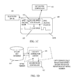
FIG. 1C is a diagram of interacting with the SST safe to lock and unlock the SST safe, according to an example embodiment; -
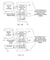
FIG. 1D is a diagram of interacting with the SST safe to acquire key information, according to an example embodiment; -
FIG. 1E is a diagram of interacting with the SST safe by a Bluetooth (trade mark) enabled device, according to an example embodiment; -
FIG. 1F is a diagram of interacting with the SST safe by a SST system component, according to an example embodiment; -
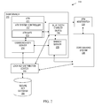
FIG. 2 is a diagram of a bank branch that incorporates a SST safe into an ATM, according to an example embodiment; -
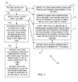
FIG. 3 is a diagram of a method for wirelessly operating a SST safe, according to an example embodiment; -
FIG. 4 is a diagram of another method for wirelessly operating a SST safe, according to an example embodiment; and -
FIG. 5 is a diagram of an SST safe, according to an example embodiment. - Reference is first made to
FIG. 1A , which is a diagram of an outside view of a secure enclosure (safe) 100, according to an example embodiment. - Although not depicted in the
FIG. 1A , the safe 100 is incorporated and securely mounted within an SST and houses valuable media, such as currency, checks, gift certificates, value tickets, coupons, goods, and the like. - The safe 100 includes a
safe door 101A through which the inside of the safe 100 can be accessed to remove the valuable media and/or replenish the safe 100 with valuable media. - Notably, the
safe door 101 A is devoid of any handle other than that is used for opening thesafe door 101A (any handle present does not unlock the safe door) and there are no holes through thesafe door 101A for lock spindle/handles. The handle used for opening the safe door is mounted on an outer surface of the safe door and does not have any component therein that extends through the safe door, thereby ensuring that the structural soundness of the safe door is not compromised in any way by the handle. -
FIG. 1B is a diagram of an inside view of a SST safe 100, according to an example embodiment. - Inside the safe 100 a variety of electromechanical components exists: a
secure microcontroller 102, alock drive 103 and a General Purpose Input/Output (GPIO) chip for locking and unlocking thesafe door 101A on direction of thelock drive 103. - The components shown in the
FIG. 1B are depicted as being situated on aninside surface 101 B of the safe door 101 A. It is noted that this does not have to be the only configuration. That is the components can exist in whole or in part on the inside walls, ceiling, and/floor of the safe 100. Moreover, the components may be covered with material from within the safe 100 so as to prevent damage to the components. -
FIG. 1C is a diagram of interacting with the SST safe 100 to lock and unlock the SST safe 100, according to an example embodiment. - The secure
micro controller 102 provides cryptographic processing for thelock drive 103, which activates the GPIOs to lock and unlock thesafe door 101A from the inside of the safe 100. Cryptographic communication and keys supplied from the securemicro controller 102 are supplied to the lock drive 103 to lock and unlock the SST safe 100. Communication to the lock drive 103 can occur via a Universal Serial Bus (USB) connection between thelock drive 103 and theSST system controller 105. Moreover, communication can occur wirelessly via a Bluetooth drive 104 (which assumes the lock drive 103 also includes a Bluetooth transceiver not shown in theFIG. 1 C) . -
FIG. 1D is a diagram of interacting with the SST safe 100 to acquire key information, according to an example embodiment. -
FIG. 1D illustrates an example embodiment of the invention for the securemicro controller 103 to acquire its master key from a securekey database 107 through an externallock distribution center 106 that interacts with the securekey database 107. In this embodiment, the securemicro controller 102 generates a public/private key pair. Next, the securemicro controller 102 provides its public key and serial number to the lockkey distribution center 106. The lockkey distribution center 106 derives a unique master key for the securemicro controller 102 from the serial number and then stores just the serial number for the secure microcontroller in the secure key database 107 (it is to be noted that the unique master key (unique to the securemicro controller 102, and based on its serial number) is not stored in the securekey database 107. The lockkey distribution center 106 encrypts the master key using the public key of the securemicro controller 102 and sends back the encrypted master key to the securemicro controller 102. The securemicro controller 102 then decrypts the encrypted master key using its private key and stores the decrypted master key within the securemicro controller 102 for future use. The securemicro controller 102 maintains complete control and access to its private key and the decrypted master key and it is not accessible outside the securemicro controller 102. - It is noted that other cryptographic techniques can be used to ensure that the master key acquired from the secure
micro controller 102 during initialization with the lockkey distribution center 106 is not exposed or compromised while on any network communication wire and the lockkey distribution center 106 does not retain or store that master key. One such other technique is discussed below with reference to theFIGS. 2-4 . -
FIG. 1E is a diagram of interacting with the SST safe 100 by a Bluetooth enableddevice 108, according to an example embodiment. - According to an unlock access embodiment, a Bluetooth enabled
device 108 makes a wireless connection to the lock drive 103 or theSST system controller 105 to acquire the serial number of the safe 100 and a random token. The Bluetooth enableddevice 108 communicates this to the lock key distribution center 106 (either via a mobile app or by a phone call to a help center associated with the lock key distribution center 106). The lock key distribution center 106 (either automatically via a software process or by manual entry by a help desk person) supplies the serial number and random token (associated uniquely with the unlock transaction being conducted) to the securekey database 107. Thesecure database 107 returns a cryptographically sealed unlock code plus the random token referenced by the serial number. That is, the random token is based on the serial number for the safe 100. The Bluetooth enableddevice 108 enters the encrypted code plus random token either directly supplying via a mobile app to the lock drive 103 or via an interface associated with the SST system controller 150. The securemicro controller 102 validates the encrypted information and the random token on behalf of thelock drive 103, and if valid thelock drive 103 unlocks thesafe door 101 A for access. -
FIG. 1F is a diagram of interacting with the SST safe 100 by a SST system component, according to an example embodiment. -
FIG. 1F shows a similar situation toFIG. 1E only the Bluetooth enableddevice 108 interacts with theSST system controller 102 directly and not the lock drive 103 to access the SST safe 100. This was discussed above with reference to theFIG. 1E as well as an alternative operational scenario for unlocking the safe 100. - It is noted that the operator of the Bluetooth enabled device is also validated and may include a customer engineer that services the SST or a replenisher that is authorized to replenish the safe 100. A variety of additional authentication mechanisms can be used to authenticate the customer engineer or replenisher and their devices (if using a Bluetooth enabled
device 108 or directly accessing an interface of the SST system controller 102). - Moreover, in an embodiment, the wireless communication is through Bluetooth Low Energy (LE) and the devices communicating wirelessly use Bluetooth LE.
- Additionally, in other embodiments, the wireless transmission need not be Bluetooth as any short-range wireless transmission can be used.
- Moreover, the variations on the cryptology used to wirelessly communicate with the safe 100 can vary, and some of these variations are discussed herein and below with other embodiments of cryptographically operating the safe 100 wirelessly.
-
FIG. 2 is a diagram 200 of abank branch 210 that incorporates a safe 213 into an Automated Teller Machine (ATM) 211, according to an example embodiment. It is to be noted that the components are shown schematically in greatly simplified form, with only those components relevant to understanding of the embodiments being illustrated. - Furthermore, the various components (that are identified in the
FIG. 2 ) are illustrated and the arrangement of the components is presented for purposes of illustration only. It is to be noted that other arrangements with more or less components are possible without departing from the teachings of SST safe and methods of operating a lock of the SST safe, presented herein and below. - The diagram 200 includes a
bank branch 210, an ATM host/switch 220, acore banking system 230, a lockkey distribution center 240, and a secure key database 250. Thebank branch 210 includes an ATM 211 (having anATM system controller 212 and an ATM safe 213), acommunication server 214, and abranch server 215. The core banking system 130 includes a remote teller manager 131. - During operation, a customer operating the
ATM 211 to conduct a transaction to deposit or receive cash from theATM 211 makes a network connection with a remote ATM host/switch 220 that routes transaction details along with approval or denial through thecore banking system 230. Tellers can assist with transactions or with customers through modes of operation for theATM 211 that routes transaction details through thecommunication server 214 to thebranch server 215 and to tellers (remote or local and not depicted in the diagram 200). Tellers can perform authorizations and overrides through thebranch server 215 connected to thecore banking system 230. - When the ATM safe 213 is in need of replenishment or in need of service from a customer engineer, a conventional ATM safe would entail opening the
ATM 211 outer compartment and with proper authorization and physical keys opening a safe door. This is changed with the teachings presented herein. - Specifically, the ATM safe 213 is accessed in one of two manners. The first manner is through a replenisher or customer engineer (CE) interacting with an administrative interface of the
ATM 211 to communicate with theATM system controller 212 or interacting with theATM system controller 212 through a short-range wireless communication, such as Bluetooth Low Energy (LE), using a Bluetooth enableddevice 216. - The second manner is direct communication with the ATM safe 213 through the Bluetooth enabled device 216 (phone, tablet, laptop, wearable processing device, etc.).
- In each manner of communication to unlock and lock the ATM safe 213, a lock drive of the ATM safe 213 is contacted (either through the
ATM system controller 212 or directly from the Bluetooth enabled device 216) to acquire a serial number and in some cases a random number from the ATM safe 213 (by the lock drive 103 using its secure microcontroller 102). This is then communicated from the Bluetooth enableddevice 216 to the lockkey distribution center 240. The lockkey distribution center 240 supplies the serial number, the random number, and, perhaps a device identifier and other credentials of the replenisher or CE to the secure key database 250. A cryptographic access code with the random number is returned to the Bluetooth enableddevice 216. The replenisher or CE then uses a mobile application to communicate the cryptographic code and random number to the lock drive 103 or through an interface to theATM system controller 212 that is then delivered to the lock drive 103 of the ATM safe 213. Assuming the cryptographic code and random number are verified by the securemicro controller 102, thesafe door 101A is unlocked electronically from theinside surface 101 B of thesafe door 101 A. The modules and interaction for achieving this was discussed above with reference to theFIGS. 1A-1F . - The ATM safe 213 has no access from the outside of the safe door 101 A. Locking and unlocking of the ATM
safe door 101A occurs from the components and processing occurring entirely from within the inside of the ATM safe 213. - It is noted that for added security, the Bluetooth pairing code between the Bluetooth enabled
device 216 and theATM system controller 212 or the lock drive 102 must be known by thelock drive 102 and the replenisher or the CE. This pairing code can change with a configured periodicity for even added security. The pairing codes are closely guarded by the ATM distributor, operator, or owner. - In an embodiment, the cryptographic processing uses a derived unique key per transaction (DUKPT) scheme with Advance Encryption Standards (AES). Each unique ATM safe 211 has its lock drive 103 seeded with an initial PIN encryption key (IPEK) with the secure
micro controller 102 during manufacture of the ATM safe 211. Each attempt to open thelock drive 103 requires a code to be generated by retrieving a current key serial number from the lock drive 103 via the securemicro controller 102 and the current key serial number is transmitted to the lockkey distribution center 240 along to the secure key database 250. The secure key database 250 then derives a current key Message Authentication Code (MAC) and calculates an AES MAC over the identifier associated with the replenisher or the CE conducting the transaction, and perhaps, a work order number supplied by the replenisher or the CE. The cryptographic operations are performed within a hardware security module (HSM) on the secure key database 250 and on the ATM safe 211 via the securemicro controller 102. What results is a 16 byte MAC that includes three sections: section one includesbytes 1 through 5 and represent an open or unlock code that must be supplied to the lock drive 103 to open the ATM safe 211, section two includes the next five bytes beginning at byte 6 and this represents a close code that is sent back from the lock drive 103 to allow the secure key database 250 to verify the ATM safe 211 locked, section three includes the next 5 bytes, which are cached by thelock drive 103 and the secure key database 250 to be used as the pairing passcode for the next attempt to connect to the lock drive 103 (the first attempt is the initial key serial number without the transaction counter). Thelock drive 103 may also independently require the replenisher or CE identifier with the unlock code to achieve unlocking of the ATM safe 211 (two-factor authentication - the unlock code from the secure key database 250 and the identifier from the replenisher or the CE). This approach eliminates the need to store large volumes of symmetric keys on the secure key database 250; a single base key (using DUKPT) can allow current unique keys on transactional bases to be derived for thousands of lock drives associated with thousands of ATMs. Unauthorized users are prevented from even connecting to thelock drive 103. Moreover, each DUKPT current key allows for one million future unique key usages before it needs to be replaced, which is more than thelock drive 103 will likely receive during its entire lifetime so there is no need to re-seed on any regular interval. The pairing codes is never transmitted to or from thelock drive 103 and is not available outside of the secure key database 250 until a next connection attempt is made to thelock drive 103. Finally, a single cryptographic operation provides all three needed codes (unlocking, locking, and deriving the next pairing code). - In an embodiment, the ATM safe 211 is the SST safe 100.
- In an embodiment, the lock
key distribution center 240 is the lockkey distribution center 106. - In an embodiment, the secure key database 250 is the secure
key database 107. - In an embodiment, the secure
key distribution center 240 and the secure key database 250 operated as a single combined entity, such as a central host. - Some of embodiments of the
FIGS. 1A-1F andFIG. 2 along with other embodiments are now discussed with reference to theFIGS. 3-5 . -
FIG. 3 is a diagram of amethod 300 for wirelessly operating a SST safe, according to an example embodiment. The software module(s) that implements themethod 200 is referred to as a "safe controller." The safe controller is implemented as executable instructions programmed and residing within memory and/or a non-transitory computer-readable (processor-readable) storage medium and executed by one or more processors of a Self-Service Terminal (SST) safe. The processor(s) of the SST safe that executes the safe controller are specifically configured and programmed to process the safe controller. The safe controller has access to one or more network connections during its processing. The network connections can be wired, wireless, or a combination of wired and wireless. - In an embodiment, the SST safe that executes the safe controller is the SST safe 100.
- In an embodiment, the SST safe that executes the safe controller is the ATM safe 213.
- In an embodiment, the safe controller is the
lock drive 103. - In an embodiment, the safe controller is a combination of the secure
micro controller 102 and thelock drive 103. - The processing of the transaction controller assumes initial key methodology and initialization as discussed above between the SST safe (having the transaction controller) and a central host (remote host from the SST). Moreover, the methodology and in some cases some keys are prefabricated (including configuration) into the components of the SST.
- At 310, the transaction controller receives, within the SST safe, a code. The code can be encrypted and/or digitally signed. The code is transaction based meaning it is good for a single transaction with the SST safe and the code is not repeated for other transactions occurring with the SST safe.
- According to an embodiment, at 311, the transaction controller obtains the code over a wired signal sent from an SST controller that is external to the SST safe and perhaps interfaced via a USB connection.
- In an embodiment, at 312, the transaction controller obtains the code over a short-range wireless signal (such as Bluetooth and others) send from a wireless device (phone, tablet, laptop computer, wearable processing device, and the like), which is in proximity to an SST. The SST safe having the transaction controller processing therein is integrated into the SST.
- At 320, the transaction controller verifies, within the SST safe, the code for access to the SST safe or for an operation to be performed on the SST safe.
- In an embodiment, at 321, the transaction controller supplies the code to a secure micro controller located within the SST safe to perform cryptographic operations on the code and obtain a result from the secure micro controller, which indicates whether at least a portion of the code is verified. Some cryptographic functions of the secure micro controller that are performed on codes on behalf of a lock drive was presented above with reference to the
FIGS. 1A-1F andFIG. 2 . - In an embodiment of 321 and at 322, the transaction controller obtains a valid unlock command and a valid re-lock command with the result. The transaction controller may also cache a portion of the result for use in generating a next cryptographic key associated with a next transaction-based code supplied to the SST safe. This scenario was discussed above with reference to the
FIG. 2 . - At 330, the transaction controller determines whether to automatically and electronically unlock or lock the SST safe in response to at least a portion of the code (which may be cryptographically transformed as well during the determination as discussed above).
- The SST safe is unlocked and locked entirely and completely from the inside of the SST safe. The SST safe includes no holes in the SST safe door used for unlocking the SST safe. Locking and unlocking the safe must occur via electronic communication with the transaction controller located and processing within the inside of the SST safe.
- According to an embodiment, at 340, the transaction controller automatically and electronically unlocks the safe door from inside the safe in response to the at least a portion of the code and/or the transaction controller automatically and electronically locks the safe door from inside the safe in response to the at least a portion of the code or another portion of that code (as discussed above).
-
FIG. 4 is a diagram of anothermethod 400 for wirelessly operating a SST safe, according to an example embodiment. The software module(s) that implements themethod 400 is referred to as a "safe host controller." The safe host controller is implemented as executable instructions programmed and residing within memory and/or a non-transitory computer-readable (processor-readable) storage medium and executed by one or more processors of one or more devices. The processors that execute the safe host controller are specifically configured and programmed to process the safe host controller. The safe host controller has access to one or more network connections during its processing. The network connections can be wired, wireless, or a combination of wired and wireless. - In an embodiment, the device that executes the safe host controller is a server.
- In an embodiment, the safe host controller is the lock
key distribution center 106. - In an embodiment, the safe host controller is lock
key distribution center 240. - In an embodiment, the safe host controller is the secure
key database 107. - In an embodiment, the safe host controller is the secure key database 250.
- In an embodiment, the safe host controller is a combination of the lock
key distribution center 106 and the securekey database 107. - In an embodiment, the safe host controller is a combination of the lock
key distribution center 240 and the secure key database 250. - At 410, the safe host controller cryptographically communicates initial key information to a SST safe over a network connection. This is initialization and synchronization between the SST safe and the safe host controller that processes on a remote host, remote from the SST to which the SST safe is integrated within.
- According to an embodiment, at 411, the safe host controller wirelessly communicates with a lock drive of the SST safe to supply the initial key information.
- In an embodiment, at 412, the safe host controller communicates the initial key information to an SST controller of an SST to which the SST safe is integrated within. The SST controller relaying initial key information to the SST safe over a wired connection. The initial key information is encrypted and cannot be decrypted or deciphered by the SST controller.
- At 420, the safe host controller dynamically supplies transactional cryptographic keys to authenticated requestors (such as replenishers or CEs). Each transaction cryptographic key unique to a unique transaction for operating the SST safe made by a unique requestor. Moreover, the SST safe can independently reproduce each transactional cryptographic key by processing the initial key information. Furthermore, the SST safe processes each transaction cryptographic key to determine whether to lock or unlock the SST safe from within an inside of the SST safe.
- According to an embodiment, at 421, the safe host controller uses verified identifiers associated with the requestors as at least a portion of the transactional cryptographic keys.
-
FIG. 5 is a diagram of an SST safe 501, according to an example embodiment. The SST safe 501 includes a variety of hardware components and software components. The software components of the SST safe 501 are programmed and reside within memory and/or a non-transitory computer-readable medium and execute on one or more processors of an SST safe 501. The SST safe 501 communicates one or more networks, which can be wired, wireless, or a combination of wired and wireless. - In an embodiment, the SST safe 501 is the SST safe 100.
- In an embodiment, the SST safe 501 is a component of the ATM safe 213.
- In an embodiment, the processing and embodiments discussed above with respect to the SST safe 100, the ATM safe 213, and the
method 300 are processed by the components of the SST safe 501 and are embodiments of the SST safe 501. - The SST safe 501 is integrated within an SST 500.
- In an embodiment, the SST 500 is the
ATM 211. - In an embodiment, the SST 500 is a gaming machine.
- In an embodiment, the SST 500 is a kiosk.
- In an embodiment, the SST 500 is a Self-Service Checkout Station.
- In an embodiment, the SST 500 is a Point-Of-Sale (POS) device.
- The SST safe 501 includes a
lock drive 503. - The
lock drive 503 is a combination of electromechanical hardware and software components. Thelock drive 503 is adapted and configured to: operate entirely within an inside of the SST safe 501, receive a wireless code sent from outside the SST safe 501, and determine whether to lock or unlock the SST safe 501 in response to at least a portion of the wireless code. - In an embodiment, the
lock drive 503 is the lock drive 103 of theFIGS. 1A-1F and theFIG. 2 and the operations discussed above with respect to thelock drive 103 are incorporated by reference herein with the securemicro controller 501. - In an embodiment, the
lock drive 503 is adapted to perform any of the processing discussed above with respect to themethod 300; thus, embodiments and processing associated with themethod 300 are incorporated by reference herein with thelock drive 503. - In an embodiment, the
lock drive 503 is further adapted and configured to disengage a lock shaft to free an access door to open when the at least a portion of the wireless code is verified as a valid unlock code. - In an embodiment, the
lock drive 503 is further adapted and configured to engage a lock shaft to secure an access door to shut and lock when at least a portion of the wireless code is verified as a valid lock code. - In an embodiment, the
lock drive 503 is further adapted and configured to obtain both a valid lock code and a valid unlock code from the wireless code for a single access transaction to the SST safe 501. - In yet another embodiment, the
lock drive 503 is further adapted and configured to send a confirmation to a remote host when the SST safe 501 is locked after having been unlocked or unlocked after having been locked. - According to an embodiment, the
lock drive 503 is further adapted and configured to receive the wireless code from a SST system controller over a wired connection. The wireless code acquired wirelessly by the SST system controller from a short-range wireless transmission of a wireless device in proximity to the SST 500. In another case, the wireless code is received wirelessly by the wireless device and an interface of the SST 500 is used by a replenisher or CE to enter the wireless code into the interface for acquisition by the SST system controller. - In an embodiment, the
lock drive 503 is further adapted and configured to directly receive the wireless code from a short-range wireless transmission of a wireless device in proximity to the SST 500. - In an embodiment, the
lock drive 503 is further adapted and configured to accept the wireless code when a wireless device in proximity to the SST 500 provides a valid wireless pairing code recognized by thelock drive 503. - According to an embodiment, the SST safe 501 also includes a secure micro controller 502. The secure micro controller 502 is adapted and configured to operate entirely within the SST safe 501, perform cryptographic operations on the wireless code on behalf of the
lock drive 503. - In an embodiment, the secure
micro controller 501 is the securemicro controller 102 of theFIGS. 1A-1F and theFIG. 2 and the operations discussed above with respect to the securemicro controller 102 are incorporated by reference herein with the securemicro controller 501. - In an embodiment, the SST safe 501 includes an access door to the SST safe 501 that is devoid of any holes used for unlocking the SST safe 501 and/or handles used for unlocking the SST safe 501.
- It should be appreciated that where software is described in a particular form (such as a component or module) this is merely to aid understanding and is not intended to limit how software that implements those functions may be architected or structured. For example, modules are illustrated as separate modules, but may be implemented as homogenous code, as individual components, some, but not all of these modules may be combined, or the functions may be implemented in software structured in any other convenient manner.
- Furthermore, although the software modules are illustrated as executing on one piece of hardware, the software may be distributed over multiple processors or in any other convenient manner.
- The above description is illustrative, and not restrictive. Many other embodiments will be apparent to those of skill in the art upon reviewing the above description. The scope of embodiments should therefore be determined with reference to the appended claims.
- In the foregoing description of the embodiments, various features are grouped together in a single embodiment for the purpose of streamlining the disclosure. This method of disclosure is not to be interpreted as reflecting that the claimed embodiments have more features than are expressly recited in each claim. Rather, as the following claims reflect, inventive subject matter lies in less than all features of a single disclosed embodiment.
Claims (15)
- A secure enclosure (100, 213, or 501) for use in a self-service terminal (500), the secure enclosure (100, 213, or 501) comprising:a lock drive (103, 503) arranged and configured to (i) operate inside the secure enclosure (100, 213, or 501), (ii) receive a wireless code sent from outside the secure enclosure (100, 213, or 501), and (iii) determine whether to lock or unlock the secure enclosure (100, 213, or 501) from inside the secure enclosure (100, 213, or 501) in response to at least a portion of the wireless code.
- The secure enclosure of claim 1 further comprising a secure microcontroller (102, 502) arranged and configured to (i) operate inside the secure enclosure (100, 213, or 501), and (ii) perform cryptographic operations on the wireless code on behalf of the lock drive (103, 503).
- The secure enclosure of claim 1 or 2, further comprising an access door (101 A) wherein the access door (101 A) has continuous structural integrity devoid of any holes therein.
- The secure enclosure of claim 3, wherein the secure enclosure (100, 213, or 501) further comprises a wireless transceiver, and wherein the lock drive (103, 503) is further arranged and configured to: disengage a lock shaft to free the access door (101A) to open when the wireless code is verified as a valid unlock code.
- The secure enclosure of claim 3 or 4, wherein the lock drive (103, 503) is further arranged and configured to: engage a lock shaft to secure the access door (101 A) shut when the wireless code is verified as a valid lock code.
- The secure enclosure of any preceding claim, wherein the lock drive (103, 503) is further arranged and configured to obtain both a valid lock code and a valid unlock code from the wireless code.
- The secure enclosure of any preceding claim, wherein the lock drive (103, 503) is further arranged and configured to: send a confirmation to a remote host (240) when the secure enclosure (100, 213, or 501) is locked after having been unlocked
- The secure enclosure of any preceding claim, wherein the lock drive (103, 503) is further arranged and configured to: receive the wireless code from a self-service terminal system controller (105, 212) over a wired connection, and wherein the wireless code is acquired wirelessly by the self-service terminal system controller (105, 212) from a short-range wireless transmission of a wireless device (108, 216) in proximity to a self-service terminal (500) into which the secure enclosure (100, 213, or 501) is integrated.
- The secure enclosure of any preceding claim, wherein the lock drive (103, 503) is further arranged and configured to: directly receive the wireless code from a short-range wireless transmission of a wireless device (108, 216) in proximity to a self-service terminal (500) into which the secure enclosure (100, 213, or 501) is integrated.
- The secure enclosure of any preceding claim, wherein the lock drive (103, 503) is further arranged and configured to: accept the wireless code when a wireless device (108, 216) in proximity to a self-service terminal (500) into which the secure enclosure (100, 213, or 501) is integrated provides a valid wireless pairing code recognized by the lock drive (103, 503).
- A method of operating a secure enclosure lock, the method comprising:receiving within a secure enclosure (100, 213, 501) a code (step 310);verifying the code within the secure enclosure (100, 213, 501) (step 320); anddetermining whether to automatically and electronically unlock or lock the secure enclosure from inside the secure enclosure (100, 213, 501) in response to at least a portion of the code (step 330).
- The method of claim 11, wherein receiving the code further includes obtaining the code over a wired signal sent from a self-service terminal controller (105, 212) external to the secure enclosure (step 311).
- The method of claim 11 or 12, wherein receiving the code further includes obtaining the code over a short-range wireless signal sent from a wireless device (108, 216) in proximity to a self-service terminal (500) into which the secure enclosure (100, 213, 501) is integrated (step 312).
- The method of any of claims 11 to 13, wherein verifying further includes supplying the code to a secure microcontroller (102, 502) located within the secure enclosure (100, 213, 501) to perform cryptographic operations on the code and obtaining a result from the secure microcontroller (102, 502) indicating whether the at least a portion of the code is verified (step 321).
- The method of claim 14, wherein obtaining the result further includes obtaining a valid unlock command and a valid re-lock command with the result (step 322).
Applications Claiming Priority (1)
| Application Number | Priority Date | Filing Date | Title |
|---|---|---|---|
| US14/470,300 US10930101B2 (en) | 2014-08-27 | 2014-08-27 | Self-service terminal (SST) safe and methods of operating a lock for the SST safe |
Publications (1)
| Publication Number | Publication Date |
|---|---|
| EP2991050A1 true EP2991050A1 (en) | 2016-03-02 |
Family
ID=53879399
Family Applications (1)
| Application Number | Title | Priority Date | Filing Date |
|---|---|---|---|
| EP15181361.5A Withdrawn EP2991050A1 (en) | 2014-08-27 | 2015-08-18 | Secure enclosure |
Country Status (3)
| Country | Link |
|---|---|
| US (1) | US10930101B2 (en) |
| EP (1) | EP2991050A1 (en) |
| CN (1) | CN105386679B (en) |
Cited By (1)
| Publication number | Priority date | Publication date | Assignee | Title |
|---|---|---|---|---|
| US20230274622A1 (en) * | 2020-05-08 | 2023-08-31 | Coinstar Asset Holdings, Llc | Kiosk-based systems and methods for direct deposit of coin and/or other cash value |
Families Citing this family (8)
| Publication number | Priority date | Publication date | Assignee | Title |
|---|---|---|---|---|
| US10438198B1 (en) | 2017-05-19 | 2019-10-08 | Wells Fargo Bank, N.A. | Derived unique token per transaction |
| DE102018106352B4 (en) * | 2018-03-19 | 2025-10-02 | Deutsche Post Ag | Authentication at mail machines |
| CN109255873A (en) * | 2018-09-14 | 2019-01-22 | 天津安伴智能科技有限公司 | Bluetooth method for unlocking, apparatus and system |
| US11212090B1 (en) | 2019-02-27 | 2021-12-28 | Wells Fargo Bank, N.A. | Derived unique random key per transaction |
| CN111119655B (en) * | 2019-12-12 | 2021-08-03 | 创斯达科技集团(中国)有限责任公司 | A lock control system, safe and lock control method based on communication module |
| CN111593995B (en) * | 2020-05-07 | 2025-01-03 | 深圳市智谷金云科技有限公司 | Precious metal storage device |
| US12101395B2 (en) * | 2020-09-29 | 2024-09-24 | Ncr Atleos Corporation | Cryptographic lock-and-key generation, distribution, and validation |
| CN116545628B (en) * | 2023-03-13 | 2023-09-19 | 广东省绿算技术有限公司 | Identity authentication method and device applied to safe, safe and storage medium |
Citations (6)
| Publication number | Priority date | Publication date | Assignee | Title |
|---|---|---|---|---|
| GB2395978A (en) * | 2002-12-02 | 2004-06-09 | Ncr Int Inc | Processor with lock control functionality |
| US20060202026A1 (en) * | 2005-03-11 | 2006-09-14 | Kim Youn J | Financial automated-teller machine and method of withdrawing cassette provided therein |
| US20110311052A1 (en) * | 2010-06-16 | 2011-12-22 | Delphian Systems, LLC | Wireless Device Enabled Locking System |
| WO2013078561A1 (en) * | 2011-11-29 | 2013-06-06 | 1556053 Alberta Ltd. | Electronic wireless lock |
| GB2499191A (en) * | 2012-02-01 | 2013-08-14 | Scotia Safes Ltd | Door interlock apparatus |
| WO2014035585A1 (en) * | 2012-08-29 | 2014-03-06 | Bank Of America Corporation | Remote safe locking and control |
Family Cites Families (22)
| Publication number | Priority date | Publication date | Assignee | Title |
|---|---|---|---|---|
| GB9002605D0 (en) * | 1990-02-06 | 1990-04-04 | Rankine Gordon | Storage devices |
| US6409086B1 (en) * | 1997-08-08 | 2002-06-25 | Symbol Technolgies, Inc. | Terminal locking system |
| US20010054025A1 (en) * | 2000-06-19 | 2001-12-20 | Adams William M. | Method of securely delivering a package |
| JP3524863B2 (en) | 2000-10-13 | 2004-05-10 | 東海理研株式会社 | Card type money locker |
| DE20201947U1 (en) | 2002-02-08 | 2002-06-13 | Hoseit, Winrich, 50996 Köln | Transportable container for storing confidential documents and the like. |
| US20050193932A1 (en) * | 2004-03-05 | 2005-09-08 | Triteq Lock And Security, L.L.C. | Safe lock with motor controlled bolts and electronic access |
| US20050204787A1 (en) * | 2004-03-19 | 2005-09-22 | Nick Ernst | Hotel in-room safe automated control and communication system |
| US20080054649A1 (en) * | 2004-09-02 | 2008-03-06 | Matsushita Electric Industrial Co., Ltd. | Door Opening/Closing Device, Keyless Entry Device with the Door Opening/Closing Device, Vehicle Door or Building Door Carrying the Keyless Entry Device |
| US20080150684A1 (en) * | 2004-11-04 | 2008-06-26 | Lock Technology B.V. | Portable entry system and method |
| EP1846863B1 (en) * | 2005-10-31 | 2010-04-21 | Nero AG | Hardware multimedia endpoint and personal computer |
| CN101375289A (en) | 2006-01-25 | 2009-02-25 | 约翰·D·布拉什公司 | Safe with controlled data transfer |
| CN101225726B (en) | 2008-01-29 | 2010-09-15 | 宁波裕泰五金有限公司 | Padlock |
| CN100577980C (en) * | 2008-02-03 | 2010-01-06 | 深圳市俊武科技有限公司 | Security box management and control system as well as management and control method |
| US7909419B2 (en) * | 2008-05-07 | 2011-03-22 | Spacesaver Corporation | Restricted access storage compartment |
| US20110298584A1 (en) * | 2010-06-04 | 2011-12-08 | Kent Biggs | Securing a cash safe with a circuit |
| WO2012087111A1 (en) | 2010-12-24 | 2012-06-28 | Mobile Money International Sdn Bhd | Electronic cheque method and system |
| WO2012122268A2 (en) * | 2011-03-08 | 2012-09-13 | Security Enhancement Systems, Llc | Lock |
| CA2834964A1 (en) * | 2011-05-02 | 2012-11-08 | Apigy Inc. | Systems and methods for controlling a locking mechanism using a portable electronic device |
| US20140068247A1 (en) * | 2011-12-12 | 2014-03-06 | Moose Loop Holdings, LLC | Security device access |
| US9232400B2 (en) | 2012-11-13 | 2016-01-05 | Alcatel Lucent | Restricted certificate enrollment for unknown devices in hotspot networks |
| US10529156B2 (en) * | 2013-05-20 | 2020-01-07 | Delphian Systems, LLC | Access control via selective direct and indirect wireless communications |
| US10096183B2 (en) * | 2014-06-02 | 2018-10-09 | Best Lockers, Llc | Mobile kiosk for intelligent securable devices system |
-
2014
- 2014-08-27 US US14/470,300 patent/US10930101B2/en active Active
-
2015
- 2015-08-18 EP EP15181361.5A patent/EP2991050A1/en not_active Withdrawn
- 2015-08-24 CN CN201510522466.2A patent/CN105386679B/en active Active
Patent Citations (6)
| Publication number | Priority date | Publication date | Assignee | Title |
|---|---|---|---|---|
| GB2395978A (en) * | 2002-12-02 | 2004-06-09 | Ncr Int Inc | Processor with lock control functionality |
| US20060202026A1 (en) * | 2005-03-11 | 2006-09-14 | Kim Youn J | Financial automated-teller machine and method of withdrawing cassette provided therein |
| US20110311052A1 (en) * | 2010-06-16 | 2011-12-22 | Delphian Systems, LLC | Wireless Device Enabled Locking System |
| WO2013078561A1 (en) * | 2011-11-29 | 2013-06-06 | 1556053 Alberta Ltd. | Electronic wireless lock |
| GB2499191A (en) * | 2012-02-01 | 2013-08-14 | Scotia Safes Ltd | Door interlock apparatus |
| WO2014035585A1 (en) * | 2012-08-29 | 2014-03-06 | Bank Of America Corporation | Remote safe locking and control |
Cited By (2)
| Publication number | Priority date | Publication date | Assignee | Title |
|---|---|---|---|---|
| US20230274622A1 (en) * | 2020-05-08 | 2023-08-31 | Coinstar Asset Holdings, Llc | Kiosk-based systems and methods for direct deposit of coin and/or other cash value |
| US12456342B2 (en) * | 2020-05-08 | 2025-10-28 | Coinstar Assett Holdings, LLC | Kiosk-based systems and methods for direct deposit of coin and/or other cash value |
Also Published As
| Publication number | Publication date |
|---|---|
| US20160063781A1 (en) | 2016-03-03 |
| CN105386679A (en) | 2016-03-09 |
| US10930101B2 (en) | 2021-02-23 |
| CN105386679B (en) | 2018-08-10 |
Similar Documents
| Publication | Publication Date | Title |
|---|---|---|
| US10930101B2 (en) | Self-service terminal (SST) safe and methods of operating a lock for the SST safe | |
| US12002314B2 (en) | Authentication of Internet of Things devices, including electronic locks | |
| US20190319944A1 (en) | System and method for electronic credentials | |
| EP0007002B1 (en) | Transaction terminal systems provided with potential user authentication | |
| CN101297327B (en) | Procedure for control of interlock and lock | |
| EP3459057B1 (en) | Dynamic key access control system and method | |
| US10964141B2 (en) | Internet-of-things (IoT) enabled lock with management platform processing | |
| CN105516077A (en) | Authenticated self-service terminal (SST) access | |
| US20220366408A1 (en) | Digital Key With Monetary Value | |
| US6253997B1 (en) | Automated teller's machine and method thereof | |
| CN104702566B (en) | Authorized use method and device of virtual equipment | |
| JP2005190447A (en) | Management system based on distributed non-connection one-time password authentication | |
| JP2018512686A (en) | Security system for cash processing equipment | |
| EP2356637A1 (en) | Card credential method and system | |
| KR100963802B1 (en) | Digital door lock using wireless signal and control method thereof | |
| KR101837063B1 (en) | Apparatus for generating one time password, apparatus and method for electric closing and opening | |
| CN101465011B (en) | Lock control system | |
| US12083992B2 (en) | Methods for shared vehicle access | |
| KR20160066975A (en) | Washing machine and Apparatus for controlling system thereof | |
| KR102936962B1 (en) | Method for enhancing security when withdrawing cash from an ATM | |
| CN112116734A (en) | Bank integrated service processor and unlocking method thereof | |
| EP2377267B1 (en) | Key issuer, key carrier, access unit and methods performed in said units | |
| WO2023149124A1 (en) | Information processing system and information processing method | |
| EP4702700A1 (en) | Controlling access based on passcode | |
| JP2026019009A (en) | Electronic key issuing method, electronic key issuing system, key device, and electric lock |
Legal Events
| Date | Code | Title | Description |
|---|---|---|---|
| PUAI | Public reference made under article 153(3) epc to a published international application that has entered the european phase |
Free format text: ORIGINAL CODE: 0009012 |
|
| AK | Designated contracting states |
Kind code of ref document: A1 Designated state(s): AL AT BE BG CH CY CZ DE DK EE ES FI FR GB GR HR HU IE IS IT LI LT LU LV MC MK MT NL NO PL PT RO RS SE SI SK SM TR |
|
| AX | Request for extension of the european patent |
Extension state: BA ME |
|
| 17P | Request for examination filed |
Effective date: 20160902 |
|
| RBV | Designated contracting states (corrected) |
Designated state(s): AL AT BE BG CH CY CZ DE DK EE ES FI FR GB GR HR HU IE IS IT LI LT LU LV MC MK MT NL NO PL PT RO RS SE SI SK SM TR |
|
| RAP1 | Party data changed (applicant data changed or rights of an application transferred) |
Owner name: NCR CORPORATION |
|
| 17Q | First examination report despatched |
Effective date: 20181116 |
|
| STAA | Information on the status of an ep patent application or granted ep patent |
Free format text: STATUS: THE APPLICATION HAS BEEN WITHDRAWN |
|
| 18W | Application withdrawn |
Effective date: 20190830 |