EP2990891A2 - Systeme und verfahren zur steuerung des energieeintrags in ein gebäude - Google Patents
Systeme und verfahren zur steuerung des energieeintrags in ein gebäude Download PDFInfo
- Publication number
- EP2990891A2 EP2990891A2 EP15181208.8A EP15181208A EP2990891A2 EP 2990891 A2 EP2990891 A2 EP 2990891A2 EP 15181208 A EP15181208 A EP 15181208A EP 2990891 A2 EP2990891 A2 EP 2990891A2
- Authority
- EP
- European Patent Office
- Prior art keywords
- control
- control volume
- temperature value
- set point
- point temperature
- Prior art date
- Legal status (The legal status is an assumption and is not a legal conclusion. Google has not performed a legal analysis and makes no representation as to the accuracy of the status listed.)
- Withdrawn
Links
Images


Classifications
-
- G—PHYSICS
- G05—CONTROLLING; REGULATING
- G05D—SYSTEMS FOR CONTROLLING OR REGULATING NON-ELECTRIC VARIABLES
- G05D23/00—Control of temperature
- G05D23/19—Control of temperature characterised by the use of electric means
- G05D23/30—Automatic controllers with an auxiliary heating device affecting the sensing element, e.g. for anticipating change of temperature
-
- G—PHYSICS
- G05—CONTROLLING; REGULATING
- G05B—CONTROL OR REGULATING SYSTEMS IN GENERAL; FUNCTIONAL ELEMENTS OF SUCH SYSTEMS; MONITORING OR TESTING ARRANGEMENTS FOR SUCH SYSTEMS OR ELEMENTS
- G05B11/00—Automatic controllers
- G05B11/01—Automatic controllers electric
- G05B11/36—Automatic controllers electric with provision for obtaining particular characteristics, e.g. proportional, integral, differential
- G05B11/42—Automatic controllers electric with provision for obtaining particular characteristics, e.g. proportional, integral, differential for obtaining a characteristic which is both proportional and time-dependent, e.g. P. I., P. I. D.
-
- G—PHYSICS
- G05—CONTROLLING; REGULATING
- G05B—CONTROL OR REGULATING SYSTEMS IN GENERAL; FUNCTIONAL ELEMENTS OF SUCH SYSTEMS; MONITORING OR TESTING ARRANGEMENTS FOR SUCH SYSTEMS OR ELEMENTS
- G05B15/00—Systems controlled by a computer
- G05B15/02—Systems controlled by a computer electric
-
- G—PHYSICS
- G06—COMPUTING OR CALCULATING; COUNTING
- G06F—ELECTRIC DIGITAL DATA PROCESSING
- G06F17/00—Digital computing or data processing equipment or methods, specially adapted for specific functions
- G06F17/10—Complex mathematical operations
- G06F17/16—Matrix or vector computation, e.g. matrix-matrix or matrix-vector multiplication, matrix factorization
Definitions
- the technical field relates generally to control systems, and more specifically, to systems and methods for improving energy efficiency for a plurality of control volumes using a hierarchical control network.
- a conventional proportional-integral-derivative controller is a type of control loop feedback mechanism that controls a process by monitoring a calculated deviation that represents the difference between a measured process variable and a desired set point. This type of controller attempts to minimize the deviation by adjusting the process control inputs.
- PID controllers are more common than typical on/off controllers and they offer several advantages such as simplicity in design and execution, they may also be largely inefficient in terms of energy usage. This disadvantage is compounded in data centers, where heating and cooling is provisioned for worst-case or peak load scenarios.
- a system for controlling each control volume of a plurality of control volumes includes a plurality of sensors corresponding to the plurality of control volumes.
- Each sensor of the plurality of sensors is configured to detect a temperature value of the control volume corresponding to the sensor, and generate a feedback signal for the control volume corresponding to the sensor based on the temperature value.
- the system further includes a primary controller configured to: receive a set point temperature value for each control volume, receive the feedback signal for each control volume, execute a linear quadratic regulator (LQR) control that is configured to determine a target set point temperature value for each control volume based on the set point temperature value for the control volume and the feedback signal for the control volume, and transmit the target set point temperature value for each control volume to a secondary controller of a plurality of secondary controllers.
- LQR linear quadratic regulator
- the plurality of secondary controllers correspond to the plurality of control volumes and each secondary controller of the plurality of secondary controllers may be configured to: receive the target set point temperature value for the control volume corresponding to the secondary controller, receive the feedback signal for the control volume corresponding to the secondary controller, and generate a control signal for the control volume corresponding to the secondary controller based on the target set point temperature value for the control volume corresponding to the secondary controller and the feedback signal for the control volume corresponding to the secondary controller.
- the system further includes at least one actuator configured to adjust a flow rate of air into each control volume based on the control signal of the control volume.
- each secondary controller may be a PID controller.
- the primary controller is further configured to generate a thermal model for the plurality of control volumes.
- the thermal model may be determined from physical data related to the plurality of control volumes and from at least one calculation based on conservation of energy.
- the at least one calculation may include at least one heat transfer term corresponding to conduction, convection, and radiation.
- the primary controller is further configured to predict an energy utilization for at least one control volume based on the thermal model.
- the state variable corresponding to temperature includes at least one temperature derived from the thermal model.
- a method of controlling temperature for each control volume of plurality of control volumes in a system includes acts of receiving a measured temperature value corresponding to each control volume of the plurality of control volumes, receiving a set point temperature value for each control volume, determining a target set point temperature value for each control volume by executing a linear quadratic regulator (LQR) control based on the set point temperature value for the control volume and the measured temperature value for the control volume, transmitting the target set point temperature, and generating a control signal for each control volume based on the target set point temperature value for the control volume and the measured temperature value for each control volume.
- LQR linear quadratic regulator
- the method further includes adjusting a flow rate of air into each control volume based on the control signal of the control volume.
- generating the control signal for each control volume is performed by implementing PID control.
- the method further includes generating a thermal model for the plurality of control volumes based on physical data related to the plurality of control volumes and from at least one calculation based on conservation of energy, wherein the at least one calculation includes at least one heat transfer term corresponding to conduction, convection, and radiation.
- the method further includes predicting an energy utilization for at least one control volume based on the thermal model.
- the state variable corresponding to temperature includes at least one temperature derived from the thermal model.
- the method further includes periodically receiving the measured temperature value for each control volume, and updating the target set point temperature value based on the periodically received measured temperature value.
- a non-transitory computer readable medium storing instructions executable by at least one processor to execute a temperature control method within a system including a plurality of control volumes.
- the instructions may be coded to instruct the at least one processor to: receive a measured temperature value for each control volume of the plurality of control volumes, receive a set point temperature value for each control volume, determine a target set point temperature value for each control volume by executing a linear quadratic regulator (LQR) control based on the set point temperature value for the control volume and the measured temperature value for the control volume, transmit the target set point temperature value for each control volume, and generate a control signal for each control volume based on the target set point temperature value for the control volume and the measured temperature value for each control volume.
- LQR linear quadratic regulator
- a primary control system is provided that is configured to receive feedback signals carrying information regarding the physical characteristics of air from within a plurality of individual control volumes that are each controlled by a secondary PID type of controller.
- the primary controller executes a mathematical method to determine target set point temperatures for each of the control volumes.
- the mathematical method executed by the primary controller takes into account the interdependency of the individual control volumes with each other, which allows the primary and secondary controllers to work together to achieve one or more states set by a user. These states relate to the desired temperature (or comfort) of each control volume and the energy utilization (or energy cost) of each control volume.
- the control system used by the primary controller is therefore capable of providing the best comfort possible within any existing cost constraint.
- references to "or” may be construed as inclusive so that any terms described using “or” may indicate any of a single, more than one, and all of the described terms.
- the term usage in the incorporated reference is supplementary to that of this document; for irreconcilable inconsistencies, the term usage in this document controls.
- titles or subtitles may be used in the specification for the convenience of a reader, which shall have no influence on the scope of the present invention.
- the control system 100 includes a plurality of control volumes 105a, 105b, and 105c, where the temperature of each control volume 110a, 110b, and 110c, respectively, is controlled by respective controllers 130a, 130b, and 130c.
- the plurality of control volumes 105a, 105b, and 105c may be located within one building or structure.
- control volumes 105a, 105b, and 105c may each be one or more rooms within an office building or residence.
- control volumes 105a, 105b, and 105c may each be one or more rooms within a temperature zone located within an office building or residence.
- Each control volume has at least one wall that forms, at least in part, the dimensions of the control volume.
- the control volume may also include a ceiling, floor, doors, or other structures that define the dimensions of the control volume.
- the control volume may be a data center.
- Data centers house electronic devices, such as servers and computer storage devices, and may be used to perform various functions, such as hosting web servers, hosting databases, or any other function that can be performed by computer.
- Controllers 130a, 130b, and 130c may each feature a PID style or type of control.
- set point temperatures 115a, 115b, and 115c are each set by a user(s) using an interface, such as a graphical user interface, coupled to the controller.
- the set point temperature corresponds to a desired temperature of the corresponding control volume.
- the set point temperature may be a temperature that reflects the desired level of comfort that a user wishes to experience while living or working or otherwise spending time within the control volume.
- the set point temperature may also be a temperature that corresponds with safe or optimum working conditions for various pieces of equipment.
- one or more racks of equipment servers may be located within the control volume. During certain operational modes, the equipment servers may produce a great deal of heat, and the set point temperature may be set to a temperature that is low enough to allow the equipment to operate without overheating.
- Each control volume 105a, 105b, and 105c contains one or more sensors 150a, 150b, and 150c, respectively, which may be positioned at one or more locations within the control volume.
- the sensors may be configured to measure and transmit information related to any one of a number of physical characteristics of the air within the control volume, such as temperature and humidity.
- each sensor 150a, 150b, and 150c may measure the temperature of each respective control volume 110a, 110b, and 110c and then transmit this information to their respective PID controller 130a, 130b, and 130c in the form of feedback signals 132a, 132b, and 132c.
- Each PID controller 130a, 130b, and 130c uses its own respective feedback signal 132a, 132b, and 132c transmitted by the one or more sensors 150a, 150b, and 150c to determine a deviation 120a, 120b, and 120c.
- the deviation is used by the controller to control physical characteristics, such as the temperature, and volume of input air masses 125a, 125b, and 125c that are directed into control volumes 105a, 105b, and 105c.
- the temperature of the air associated with the input air mass may correspond to the set point temperature.
- the temperature of the input air mass may correspond to a temperature that is selected to bring the control volume temperature closer to the set point temperature.
- the temperature of the air directed into the control volume may be at a temperature that is higher than the set point temperature in order to bring the temperature of the air within the control volume to the set point temperature at a faster rate.
- a larger deviation results in more air at a certain temperature and flow rate being directed into the control volume, whereas a smaller deviation results in less airflow into the control volume.
- the control system 100 may further include one or more actuators 155a, 155b, and 155c that are associated with respective input air masses 125a, 125b, and 125c and the respective controllers 130a, 130b, and 130c.
- the actuators may provide or otherwise assist in controlling the physical characteristics and volume of the air mass that is directed into the control volume.
- the actuators 155a, 155b, and 155c may be in communication with a cooler (or heater) that is associated with one or more control volumes and functions to provide cooled or heated input air masses 125a, 125b, and 125c to the control volume via the actuators 155a, 155b, and 155c.
- deviations 120a, 120b, and 120c which are each calculated by controllers 130a, 130b, and 130c, respectively, represent the difference between the actual value of one or more physical properties of the air within the each control volume, such as control volume temperatures 110a, 110b, and 110c, and the respective set point value set by a user, such as temperatures 115a, 115b, and 115c.
- the value of the deviation is as small as possible.
- the controller 130a uses the actuator 155a to direct the input air mass 125a with a certain temperature and air flow value into the control volume 105a.
- the controller 130a sends a signal or otherwise communicates with the actuator 155a in directing air with a temperature value, such as air with at temperature value of the set point temperature, and a certain flow rate into the control volume 105a.
- the controller may be configured to "request” or otherwise obtain information about the air in the control volumes via the sensors and feedback signals at periodic time intervals. For example, the controller may request feedback information every five minutes. In other embodiments, the controller may be constantly or continuously obtaining information via the feedback signals.
- the actuator is configured to manipulate a characteristic of the airflow supplied to the control volume.
- the actuator may include a system or device for supplying air at a certain flow rate, temperature, humidity, and/or pressure.
- the actuator may include or be in communication with a humidifier or dehumidifier configured to vary the absolute humidity of the airflow supplied to the control volume.
- the actuator may include or be in communication with a cooling or heating system that provides cooled or heated air to the control volume.
- the actuator may also include a damper system that includes one or more dampers, such as venting devices, and may also include other devices such as valves and ducts.
- the actuator may include sensors to determine one or more physical properties of the air being supplied to the control volume. These sensors may also be configured to transmit this information to a controller or other component of the system.
- the control system 100 described above in reference to FIG. 1 includes three separate control volumes 105a, 105b, and 105c.
- Each control volume 105a, 105b, and 105c is locally and independently controlled by the respective controller 130a, 130b, and 130c.
- the controllers 130a, 130b, 130c may not be programmed to regulate the amount of energy consumed to reach the desired level of comfort.
- This method of control may waste energy.
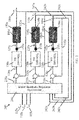
- FIG. 2 illustrates a control system, generally indicated at 200, that features some of the same elements discussed above in reference to FIG. 1 , such as the plurality of control volumes 105a, 105b, and 105c, controllers 130a, 130b, and 130c, sensors 150a, 150b, and 150c, and actuators 155a, 155b, and 155c.
- control system 200 further includes a primary controller 240 that is used to provide target set point temperatures 235a, 235b, and 235c.
- the target set point temperatures 235a, 235b, and 235c are each used by their respective secondary controller 130a, 130b, and 130c to determine the respective deviations 120a, 120b, and 120c.
- the primary controller 240 receives each respective set point temperature 115a, 115b, and 115c from the user instead of each individual controller 130a, 130b, and 130c receiving these values. Further, the primary controller 240 receives feedback signals 242a, 242b, and 242c transmitted by corresponding sensors 150a, 150b, and 150c in a similar manner as secondary controllers 130a, 130b, and 130c receive feedback signals 132a, 132b, and 132c, respectively. Primary controller 240 is configured to accommodate any interdependency that exists between the control volumes 105a, 105b, and 105c.
- control volume 105a may influence or otherwise affect one or more physical characteristics of the air within either one or both of control volumes 105b and 105c.
- control volumes 105a-105c are each supplied by the same air handler.
- the primary controller 240 provides the target set point temperatures 235a, 235b, and 235c based on a number of factors.
- these factors take into account the interdependency of the control volumes 105a, 105b, and 105c with each other.
- One such factor includes the comfort level, or desired temperature (such as the set point temperatures 115a, 115b, and 115c), that is input by one or more users by using an interface with the primary controller.
- Another factor includes energy utilization, or the energy cost by one or more of the control volumes.
- the desired comfort level of each respective control volume is indicated at 360, and 370 indicates the energy utilization associated with each respective control volume.
- 370 represents the output of the control system in terms of either heated or cooled air flow that is provided to each of the control volumes to reach the desired level of comfort. This is also indicative of the energy spent to reach this level of comfort
- Function 1 is a function of the difference between the desired temperatures in the control volumes and the actual temperatures in the control volumes. Function 1 therefore forms an integral part of the control scheme programmed into the primary controller 240, with the objective being to minimize "J.” When Function 1 is minimized, the deviations from the desired temperatures are minimized while at the same time taking into account the energy input to the control volumes.
- the quadratic function represented by Function 1 is also referred to as the Linear Quadratic Regulator (LQR) and represents an advanced control technique that utilizes state space representation. State space representations are useful for systems with multiple inputs and multiple outputs, since multiple first-order differential equations can be analyzed in vector form.
- one of the factors 360 and 370 in Function 1 comes at the cost, or detriment, of the other.
- a desired comfort level 360 such as the temperature set by a user for a control volume
- low energy utilization 370 comes at the cost of the desired comfort level 360.
- the balance between these two factors is used in Function 1 as one determining factor in calculating the target set point temperatures 235a, 235b, and 235c.
- the primary controller 240 uses the linear quadratic relationship of Function 1 to compute the target control inputs for the respective secondary or PID controllers 130a, 130b, and 130c.
- a balance between the comfort 360 and cost 370 terms of Function 1 is determined by one or more users, and may be input by a user using an interface with the primary controller 240. In other embodiments, the desired balance may be determined by a computer system.
- the term "Q" in Function 1 represents a weight matrix for the comfort term 360, which is also represented as 365 in FIG. 3 .
- the term "R” in Function 1 represents a weight matrix for the energy utilization term 370, which is also represented as 375 in FIG. 3 .
- the weight matrices for Q and R would each be represented by a 3x3 matrix.
- the values for each control volume may vary accordingly. For example, a user may decide that the desired comfort of the first control volume 105a should carry more weight than the desired comfort level of the second control volume 105b.
- the first control volume 105a may be an office space that is used during the daytime
- the second control volume 105b may be a residential space that is occupied only during evenings and overnight.
- the above examples use matrix values that included numerical values of 0.1 and 10, but it is appreciated that the values and/or ranges of values may vary depending on the application, including the size and nature of the control volume(s).
- the primary controller 240 may be programmed or otherwise configured to vary or otherwise change the weighting matrices Q and R at predetermined or periodic time intervals. For example, during periods of the day where energy costs are high, the desire to keep energy costs low may be more highly desired, which will be reflected in the values that populate the weighting matrix R.
- the members of the input vector 380 therefore affect the state vector variables, including the temperature of the wall and temperature of the control volume, as discussed further below.
- the primary controller 240 may use a thermal model as part of its control scheme.
- the primary controller may use the thermal model in determining the state and/or input variables of the state equation represented in Function 1.
- heat capacity describes how much energy is required to increase the temperature by a specified amount, which is proportional to the mass of the object.
- thermal conduction is the process of heat transfer from one part of a body at a higher temperature to another (or between bodies in direct contact) at a lower temperature.
- thermal convection is the transfer of heat from one part of a fluid, such as a gas, to another part at a lower temperature by mixing of fluid particles.
- Heat transfer by convection may take place, for example, at the surface of walls, floors, and roofs.
- FIG. 4 Also featured in FIG. 4 is the concept of heat transfer via radiation, which is the heat transfer from a body by virtue of its temperature.
- ⁇ is the emissivity of the building's surface, i.e., the wall
- ⁇ is the Stefan-Boltzmann constant
- A is the area of the exposed surface, i.e., surface area of the wall
- T s is the temperature of the surface, i.e., a small surface such as a radiator
- T sur is the temperature of the surroundings, which in certain instances, is the surface temperature of the wall.
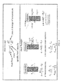
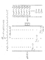
- FIG. 5 An example of a simple thermal model for a single control volume is shown in FIG. 5 .
- the room includes four walls, W1-W4, and featured at the bottom of FIG. 5 is a differential heat equation whose solution provides the temperature distribution in a stationary medium and is based on applying conservation of energy:
- C r 1 d T 1 d t T w 1 - T 1 R i + R w 2 1 + T w 2 - T 1 R i + R w 2 2 + T w 3 - T 1 R i + R w 2 3 + T w 4 - T 1 R i + R w 2 4 + m ⁇ c p a T 0 - T 1 + q int 1
- the left side of the equation represents the change in thermal energy storage and the first four terms on the right side of the equation represent the net transfer of thermal energy into the control volume (assuming energy transfer is exclusively by conduction).
- the fifth term is the heat contribution from the incoming air mass and the last term represents thermal energy
- each wall T wi is determined by a number of factors, including the thickness and type of material used in the wall's construction, and the presence or absence of any insulation material.
- the position of the wall within the room and within the overall structure may also influence its temperature. For example, walls adjacent the outside environment may be colder or hotter than interior walls, depending on the temperature and/or other environmental conditions of the outside environment.
- Building construction design information such as the thermal conductivity of materials, the size of the rooms, etc. may be used to determine a multidimensional heat transfer model of the building. This information may be input by a user or obtained through other means to the primary controller.
- the thermal model may be used to determine the energy input into a building.
- the thermal model may be used by the primary controller 240 as part of its calculations in determining the target set point temperatures 235a, 235b, and 235c.
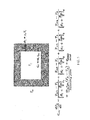
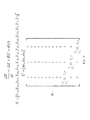
- the thermal model for the single control volume shown in FIG. 5 may be expanded to include three control volumes 105a, 105b, 105c, as discussed above, which is represented graphically in FIG. 6 .
- FIG. 6 features a thermal model, generally indicated at 600, for the three control volumes 105a, 105b, and 105c, which each contain air at temperatures 110a, 110b, and 110c, respectively. Also included are the input air masses, represented by 125a, 125b, and 125c respectively.
- the thermal model 600 also includes walls W1-W10, which represent walls that comprise the control volumes.
- control volume 105a is bounded by four walls, W1, W2, W8, and W10 and control volume 105b is bounded by walls W8, W3, W4, and W9, where W8 is shared by both control volumes 105a and 105b.
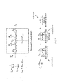
- a thermal circuit including a differential heat balance equation, of a single wall is shown in FIG. 7 .
- the thermal circuit is based on an analogy between diffusion of heat and electrical charge.
- electrical resistance is associated with the transfer of electricity
- a thermal resistance may be associated with the transfer of heat.
- R i L h A
- A is the area of the wall
- L is the thickness of the wall
- h is the thermal conductivity of the wall.
- one or more of the properties associated with the heat transfer equations such as the thermal conductivity of the wall (h), or the area of the wall (A) may be input or otherwise communicated to the primary controller.
- These properties including one or more other properties discussed below in reference to conduction, convection, and radiation, comprise physical data that is used by the system to generate and construct the thermal model.
- the thermal circuit is a representation of the resistance to heat flow as though it were a resistor, and the heat storage elements can be represented as capacitors. Further, temperature can be represented as potential.
- Equation 1 External disturbances such as heat generation are omitted from Equation 1.
- the transmission of heat through the wall may thus be considered as a network with three resistances in series, each of which is discussed further below.
- the thermal model may therefore be derived from using one or more of the heat transfer equations or terms discussed above, for example, using Equation 1, and thus may be used to solve for T w1 -T w10 .
- the thermal model is therefore configured to take into account heat transfer in both internal and external walls. Other surfaces may also be included in the thermal model, including ceilings, roofs, floors, doorways, etc.
- the x(t) T term which is expressed as 362 in the mathematical expression of FIG. 3 , represents the state variable that changes over time, which in this instance is the temperature of each individual wall, T w1 -T w10 and the temperature of the air in each control volume T 1 -T 3 (110a, 110b, and 110c).
- C wi is the heat capacitance of wall i
- R j is the thermal resistance of air in control volume j
- R wi is the thermal resistance of wall i
- C rj is the specific heat capacity of air in control volume j
- d(t) is the matrix shown in FIG. 8A , where ⁇ represents the absorption coefficient of the wall, which in this example is assumed to be constant for all the walls, q radi ⁇ is the thermal energy generation attributed to radiation for wall i, and A i is the surface area of wall i, as discussed above in reference to heat transfer attributed to radiation. Further, T ⁇ is the temperature of air external to the wall, as discussed above in reference to heat transfer attributed to convection, and q intj is the thermal energy generated from within the control volume j, also discussed above.
- external disturbances such as heat generation are included in the state space model expressed by Equation 2.
- Equation 2 Equation 2.
- g(X,U) is shown in FIG.
- To represents the temperature of the cooled (or heated) air mass provided to each control volume from the cooler (or heater) using one or more actuators, as discussed above.
- To is considered to be a constant value for all control volumes.
- C p is the specific heat capacity of air, and in this example, is considered to be constant at a value of 1.006 kJ/kg ⁇ K.
- the system represented in Equation 2 is non-linear, in that "g" is a function of both the state (X) and the input (U).
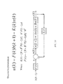
- Equation 3 is therefore a Jacobian linearization which generally states that a nonlinear differential equation can be accurately approximated by a first degree linear differential equation so long as the perturbations to the system are small.
- the system is limited around an operating point, or equilibrium point, and the input change is limited within a small range around this equilibrium point.
- the equilibrium point may be the set point temperature (such as 115a, 115b, or 115c).
- the linear state space model applies when the control volume temperature (such as 110a, 110b, and 110c) does not deviate widely from the set point temperature. Under these conditions, the first degree linear equation is a good enough approximation model to determine the control parameters.
- a discrete implementation of Function 1 may be represented by Equation 4 below, which is also shown in FIG. 10 :
- u k F k b k + 1 - K k x k
- K k R + B T P k + 1 B - 1 B T P k + 1 A
- F k - R + B T P k + 1 B - 1 B T
- the control signal for the time index k for each secondary controller is defined by Equation 4.
- the secondary controller may be a PID controller.
- the primary controller 240 is configured to use energy information, such as energy information generated by the thermal model discussed above, to predict the energy utilization required to achieve a desired environment.
- energy information such as energy information generated by the thermal model discussed above
- the thermal model may be used to calculate, or predict, the value of the state at X(t+1) at time "t+1". Once X(t+1) is determined, then the input variable can be determined.
- the primary controller 240 may therefore be configured to use both measured and predicted values in determining the target set point temperatures 235a, 235b, and 235c.
- the thermal model may also be expanded to use heat transfer information from other components of the building or structure housing the control volumes, such as the ceiling, floors and roof. Heat transfer information similar to that described in reference to FIG. 7 may be used in determining the relevant energy calculations for the building.
- control volumes may be included in the control system 200 discussed above.
- the number of control volumes included in the control system may include any number of control volumes that are capable of functioning with the control scheme as disclosed.
- the control system is also capable of controlling other desired physical properties of the air, such as humidity.
- the sensors within the control volume may be configured to transmit humidity data to the primary controller, which is then used by the primary controller in combination with a set point humidity (determined or otherwise established by a user or computer system) to determine a target set point humidity.
- Function 1 may be modified to further include a desired humidity in a treatment that is similar to that for the temperature.
- the primary controller 240 described above uses a control strategy that offers several advantages over PID or other on/off types of control strategies configured for existing HVAC systems.
- the Linear Quadratic Regulator included in the control scheme of primary controller 240 allows actual energy utilization and predicted energy utilization to be taken into account, which reduces the energy demands of the building. The reduced energy demands lead to cost savings in operating the building or other structure that uses the control scheme.
- the primary controller is capable of being retrofitted into an existing structure that uses an already-existing PID or other type of on/off controller.
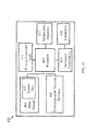
- FIG. 11 illustrates a temperature control system 400 that is configured to control the temperature of the air within a plurality of control volumes.
- the temperature control system 400 comprises a processor 402 coupled to data storage 404, an optional communication network interface 406, secondary controller(s) 416, temperature sensor(s) 412, and a primary controller 414.
- the data storage 404 may also optionally store system data 410.
- the secondary controller(s) 416 are coupled to one or more actuators 408.
- the processor 402 performs a series of instructions that result in manipulated data that is stored and retrieved from the data storage 404.
- the processor 402 is a commercially available processor, such as a processor manufactured by Texas Instruments, Intel, AMD, Sun, IBM, Motorola, and ARM Holdings, for example. It is appreciated that the processor 402 may be any type of processor, multiprocessor or controller, whether commercially available or specially manufactured.
- the processor 402 is configured to execute a conventional real-time operating system (RTOS), such as RTLinux.
- RTOS real-time operating system
- the RTOS may provide platform services to application software, such as some software associated with the primary controller 414 and secondary controller 416 discussed above. These platform services may include inter-process and network communication, file system management, and standard data store manipulation.
- application software such as some software associated with the primary controller 414 and secondary controller 416 discussed above.
- platform services may include inter-process and network communication, file system management, and standard data store manipulation.
- One or more operating systems may be used, and examples are not limited to any particular operating system or operating system characteristic.
- the processor 402 may be configured to execute a non-real time operating system, such as BSD or GNU/Linux. It is appreciated that the processor 402 may execute an Operating System Abstraction Library (OSAL).
- OSAL Operating System Abstraction Library
- the primary controller 414 and secondary controller 416 may be implemented using hardware, software, or a combination of hardware and software.
- the primary controller 414 and secondary controller 416 are implemented as software components that are stored within the data storage 404 and executed by the processor 402.
- the instructions included in the primary controller 414 program the processor 402 to generate control signals for one or more actuators 408 coupled to the secondary controller 416.
- the instructions included in the primary controller 414 may be based on LQR control strategy.
- the primary controller 414 and secondary controller 416 may each be an application-specific integrated circuit (ASIC) that is coupled to the processor 402.
- ASIC application-specific integrated circuit
- examples of the primary controller 414 and secondary controller 416 are not limited to a particular hardware or software implementation.
- the temperature control system 400 may execute one or more processes to control the temperature of the air within each control volume. One example of a process performed by the primary controller 414 and secondary controller 416 is discussed further below with reference to FIG 12 .
- one or more of the components disclosed herein may read parameters that affect the functions they perform. These parameters may be physically stored in any form of suitable memory including volatile memory, such as RAM, or nonvolatile memory, such as a flash memory or magnetic hard drive.
- volatile memory such as RAM
- nonvolatile memory such as a flash memory or magnetic hard drive.
- the parameters may be logically stored in a proprietary data structure, such as a database or file defined by a user mode application, or in a commonly shared data structure, such as an application registry that is defined by an operating system.
- the data storage 404 includes a computer readable and writeable nonvolatile data storage medium configured to store non-transitory instructions and data.
- the data storage 404 includes processor memory that stores data during operation of the processor 402.
- the processor memory includes a relatively high performance, volatile, random access memory such as dynamic random access memory (DRAM), static memory (SRAM) or synchronous DRAM.
- the processor memory may include any device for storing data, such as a non-volatile memory, with sufficient throughput and storage capacity to support the functions described herein.
- the processor 402 causes data to be read from the nonvolatile data storage medium into the processor memory prior to processing the data.
- the processor 402 copies the data from the processor memory to the non-volatile storage medium after processing is complete.
- a variety of components may manage data movement between the non-volatile storage medium and the processor memory and examples are not limited to particular data management components. Further, examples are not limited to a particular memory, memory system, or data storage system.
- the instructions stored on the data storage 404 may include executable programs or other code that can be executed by the processor 402.
- the instructions may be persistently stored as encoded signals, and the instructions may cause the processor 402 to perform the functions described herein.
- the data storage 404 also may include information that is recorded, on or in, the medium, and this information may be processed by the processor 402 during execution of instructions.
- the medium may be optical disk, magnetic disk, or flash memory, among others, and may be permanently affixed to, or removable from, the temperature control system 400.
- the system data 410 includes data used by the primary controller 414 to improve the temperature control strategy. More particularly, the system data 410 may include physical data related to the control volumes, such as data discussed above that is used for generating a thermal model of the system.
- the system data 410 may be stored in any logical construction capable of storing information on a computer readable medium including, among other structures, flat files, indexed files, hierarchical databases, relational databases or object oriented databases. These data structures may be specifically configured to conserve storage space or increase data exchange performance.
- various examples organize the system data 410 into particularized and, in some cases, unique structures to perform the functions disclosed herein.
- the data structures are sized and arranged to store values for particular types of data, such as integers, floating point numbers, character strings, arrays, linked lists, and the like. It is appreciated that the primary controller 414 and the system data 410 may be combined into a single component or re-organized so that a portion of the system data 410 is included in the primary controller 414. Such variations in these and the other components illustrated in FIG. 11 are intended to be within the scope of the embodiments disclosed herein.
- the temperature control system 400 also includes communication network interface 406, actuator(s) 408, and temperature sensor(s) 412.
- Each of these components is a specialized device or is configured to exchange (i.e., send or receive) data with one or more specialized devices that may be located within the temperature control system 400 or elsewhere.
- Each of these components may include hardware, software, or a combination of both hardware and software that functions to physically and logically couple one or more elements with one or more other elements of the temperature control system 400. This physical and logical coupling enables the temperature control system 400 to communicate with and, in some instances, power or control the operation of one or more components.
- the communication network interface 406 may be coupled to a communication device that is powered and/or controlled by the processor 402 through the communication network interface 406.
- the hardware and software components of the communication network interface 406, actuator(s) 408, and temperature sensor(s) 412 implement a variety of coupling and communication techniques.
- these components use leads, cables or other wired connectors as conduits to exchange data.
- wireless technologies such as radio frequency or infrared technology are used.
- Software components that may be included in these devices enable the processor 402 to communicate with other components of the temperature control system 400.
- the software components may include elements such as objects, executable code, and populated data structures.
- the communication network interface 406, actuator(s) 408, and temperature sensor(s) 412 further include components configured to convert analog information into digital information, and vice-versa, to enable the processor 402 to communicate with one or more components of the temperature control system 400.
- the temperature control system 400 includes the communication network interface 406.
- the components of the communication network interface 406 couple the processor 402 to one or more communication devices.
- the temperature control system 400 can transmit secure data via the communication network interface 406 using a variety of security measures.
- the network interface 406 includes both a physical interface configured for wireless communication and a physical interface configured for wired communication.
- the temperature control system 400 is configured to exchange temperature or other types of information with an external system via one or more communication devices coupled to the communication network interface 406.
- the secondary controller 416 shown in FIG. 2 includes a combination of hardware and software components that allow the temperature control system 400 to communicate with one or more actuators 408 (e.g., actuators 155a, 155b, and 155c discussed above in reference to FIGS. 1 and 2 ).
- the secondary controller 416 may generate one or more control signals based on data transmitted from the processor 402 and originating from the primary controller 414, and communicate the control signals to the actuator(s) 408 to adjust the flow rate of air into the control volumes.
- FIG. 12 illustrates an embodiment of a temperature control process 500.
- the temperature control process 500 enables the primary controller and secondary controller(s) to control the temperature of the air within one or more control volumes (e.g., 105a, 105b, and 105c).
- the temperature control system receives measured temperature values from one or more sensors (e.g., sensors150a, 150b, and 150c) and set point temperature values (e.g., 115a, 115b, and 115c), respectively. According to some embodiments, the temperature control system may receive one or both of these values periodically. Further, one or both of these values may be stored, for instance, in a data storage device and then retrieved for use in act 506. In act 506, the temperature control system determines a target set point temperature value for each control volume. For example, the primary controller (e.g., 240) may execute LQR control based on the measured temperature values and the set point temperature values.
- the primary controller e.g., 240
- the primary controller is also configured to generate a thermal model, shown as act 512, which may also contribute toward determining the target set point temperature values.
- the thermal model may be determined from physical data related to the plurality of control volumes, and may include calculations based on conservation of energy using one or more heat transfer terms corresponding to conduction, convection, and radiation.
- the temperature control system transmits the target set point temperature value.
- the target set point temperature value may be transmitted to the secondary controller (e.g., secondary controllers 130a, 130b, and 130c).
- a control signal is generated for each control volume.
- the secondary controller may generate a control signal based on the target set point temperature value and the measured temperature value to one or more actuators that are configured to adjust a flow rate of air into each control volume.
- receiving measured temperature values 502 and receiving set point temperature values 504 may be combined into a single stage.
Landscapes
- Engineering & Computer Science (AREA)
- Physics & Mathematics (AREA)
- General Physics & Mathematics (AREA)
- Automation & Control Theory (AREA)
- Mathematical Physics (AREA)
- General Engineering & Computer Science (AREA)
- Computational Mathematics (AREA)
- Mathematical Optimization (AREA)
- Mathematical Analysis (AREA)
- Pure & Applied Mathematics (AREA)
- Data Mining & Analysis (AREA)
- Theoretical Computer Science (AREA)
- Algebra (AREA)
- Databases & Information Systems (AREA)
- Software Systems (AREA)
- Computing Systems (AREA)
- Air Conditioning Control Device (AREA)
- Feedback Control In General (AREA)
- Control Of Temperature (AREA)
Applications Claiming Priority (1)
| Application Number | Priority Date | Filing Date | Title |
|---|---|---|---|
| US14/470,311 US9772633B2 (en) | 2014-08-27 | 2014-08-27 | Systems and methods for controlling energy input into a building |
Publications (2)
| Publication Number | Publication Date |
|---|---|
| EP2990891A2 true EP2990891A2 (de) | 2016-03-02 |
| EP2990891A3 EP2990891A3 (de) | 2016-07-13 |
Family
ID=53886929
Family Applications (1)
| Application Number | Title | Priority Date | Filing Date |
|---|---|---|---|
| EP15181208.8A Withdrawn EP2990891A3 (de) | 2014-08-27 | 2015-08-17 | Systeme und verfahren zur steuerung des energieeintrags in ein gebäude |
Country Status (3)
| Country | Link |
|---|---|
| US (1) | US9772633B2 (de) |
| EP (1) | EP2990891A3 (de) |
| CN (1) | CN105388756B (de) |
Cited By (1)
| Publication number | Priority date | Publication date | Assignee | Title |
|---|---|---|---|---|
| WO2019220679A1 (en) * | 2018-05-16 | 2019-11-21 | Mitsubishi Electric Corporation | Thermal conditioning system and method |
Families Citing this family (2)
| Publication number | Priority date | Publication date | Assignee | Title |
|---|---|---|---|---|
| US10942492B2 (en) * | 2017-01-05 | 2021-03-09 | Atmel Corporation | Autonomous process control peripheral |
| DE102017205033B4 (de) * | 2017-03-24 | 2024-02-08 | Viessmann Werke Gmbh & Co. Kg | Verfahren und System zum internetgestützten Optimieren von Parametern einer Heizungsregelung |
Citations (2)
| Publication number | Priority date | Publication date | Assignee | Title |
|---|---|---|---|---|
| US7218996B1 (en) * | 2006-06-26 | 2007-05-15 | Hewlett-Packard Development Company, L.P. | Method for thermally managing a room |
| US20130151019A1 (en) * | 2011-12-12 | 2013-06-13 | Vigilent Corporation | Controlling air temperatures of hvac units |
Family Cites Families (17)
| Publication number | Priority date | Publication date | Assignee | Title |
|---|---|---|---|---|
| JPH01217601A (ja) * | 1988-02-26 | 1989-08-31 | Ricoh Res Inst Of Gen Electron | サーボ制御装置 |
| US5867384A (en) | 1997-07-08 | 1999-02-02 | Johnson Services Company | Feedback controller |
| US6139627A (en) * | 1998-09-21 | 2000-10-31 | The University Of Akron | Transparent multi-zone crystal growth furnace and method for controlling the same |
| JP2001255903A (ja) * | 2000-03-14 | 2001-09-21 | Toshiba Corp | プロセス制御システム |
| US6554198B1 (en) * | 2000-05-05 | 2003-04-29 | Automated Logic Corporation | Slope predictive control and digital PID control |
| US6453993B1 (en) * | 2000-05-17 | 2002-09-24 | Carrier Corporation | Advanced starting control for multiple zone system |
| US7640760B2 (en) * | 2005-03-25 | 2010-01-05 | Hewlett-Packard Development Company, L.P. | Temperature control using a sensor network |
| US7894944B2 (en) * | 2007-07-06 | 2011-02-22 | Microsoft Corporation | Environmental monitoring in data facilities |
| CN102084302A (zh) | 2008-07-02 | 2011-06-01 | 格雷索明尼苏达有限公司 | 加热器和电机控制 |
| US20110054701A1 (en) * | 2009-08-27 | 2011-03-03 | Blueair Controls, Inc. | Energy saving method and system for climate control system |
| US8639651B2 (en) * | 2009-10-30 | 2014-01-28 | Hewlett-Packard Development Company, L. P. | Manipulating environmental conditions in an infrastructure |
| CN102393640A (zh) * | 2011-10-21 | 2012-03-28 | 哈尔滨工程大学 | 一种低频展宽的非线性反馈控制装置及方法 |
| US9348325B2 (en) * | 2012-01-30 | 2016-05-24 | Johnson Controls Technology Company | Systems and methods for detecting a control loop interaction |
| US9436179B1 (en) * | 2013-03-13 | 2016-09-06 | Johnson Controls Technology Company | Systems and methods for energy cost optimization in a building system |
| US20140365017A1 (en) * | 2013-06-05 | 2014-12-11 | Jason Hanna | Methods and systems for optimized hvac operation |
| CN103454921B (zh) * | 2013-08-30 | 2017-04-12 | 中国人民解放军第二炮兵工程大学 | 飞行控制系统非线性跟踪控制器设计的正切线性化方法 |
| TWI551830B (zh) * | 2013-12-12 | 2016-10-01 | 財團法人工業技術研究院 | 用於暖通空調系統之控制裝置及其方法 |
-
2014
- 2014-08-27 US US14/470,311 patent/US9772633B2/en not_active Expired - Fee Related
-
2015
- 2015-08-17 EP EP15181208.8A patent/EP2990891A3/de not_active Withdrawn
- 2015-08-26 CN CN201510531524.8A patent/CN105388756B/zh not_active Expired - Fee Related
Patent Citations (2)
| Publication number | Priority date | Publication date | Assignee | Title |
|---|---|---|---|---|
| US7218996B1 (en) * | 2006-06-26 | 2007-05-15 | Hewlett-Packard Development Company, L.P. | Method for thermally managing a room |
| US20130151019A1 (en) * | 2011-12-12 | 2013-06-13 | Vigilent Corporation | Controlling air temperatures of hvac units |
Non-Patent Citations (1)
| Title |
|---|
| QI QI, SHIMING DENG: "Building and Environment", vol. 44, 4 November 2008, ELSEVIER, article "Multivariable control of indoor air temperature and humidity in a directexpansion (DX) air conditioning (A/C) system", pages: 1659 - 1667 * |
Cited By (1)
| Publication number | Priority date | Publication date | Assignee | Title |
|---|---|---|---|---|
| WO2019220679A1 (en) * | 2018-05-16 | 2019-11-21 | Mitsubishi Electric Corporation | Thermal conditioning system and method |
Also Published As
| Publication number | Publication date |
|---|---|
| CN105388756A (zh) | 2016-03-09 |
| EP2990891A3 (de) | 2016-07-13 |
| CN105388756B (zh) | 2018-07-06 |
| US20160062374A1 (en) | 2016-03-03 |
| US9772633B2 (en) | 2017-09-26 |
Similar Documents
| Publication | Publication Date | Title |
|---|---|---|
| Joe et al. | A model predictive control strategy to optimize the performance of radiant floor heating and cooling systems in office buildings | |
| Maasoumy | Modeling and optimal control algorithm design for HVAC systems in energy efficient buildings | |
| US8818563B2 (en) | System for controlling room temperature in a building using a free energy source, an additional energy source, and predictive control | |
| Schmelas et al. | Adaptive predictive control of thermo-active building systems (TABS) based on a multiple regression algorithm | |
| Maasoumy et al. | Selecting building predictive control based on model uncertainty | |
| Minakais et al. | Database-driven iterative learning for building temperature control | |
| Mendes et al. | A Matlab-based simulation tool for building thermal performance analysis | |
| Thomas et al. | Feed-forward in temperature control of buildings | |
| Bursill et al. | Multi-zone field study of rule extraction control to simplify implementation of predictive control to reduce building energy use | |
| Yu et al. | Model-based predictive control for building energy management: Part II–Experimental validations | |
| EP2990891A2 (de) | Systeme und verfahren zur steuerung des energieeintrags in ein gebäude | |
| Zhu et al. | Heating, Ventilation, and Air Conditioning (HVAC) Temperature and Humidity Control Optimization Based on Large Language Models (LLMs). | |
| Wen et al. | Development and validation of online models with parameter estimation for a building zone with VAV system | |
| Thilker et al. | Learnings from experiments with MPC for heating of older school building | |
| Shamachurn et al. | Real‐Time Model Predictive Control of Air‐Conditioners Through IoT—Results From an Experimental Setup in a Tropical Climate | |
| Wemhoff | Application of optimization techniques on lumped HVAC models for energy conservation | |
| Charvátová et al. | Optimizing Home Heating: A Numerical Approach to Assessing Radiator, Floor, and Ceiling Heaters | |
| Wen et al. | Development and validation of online parameter estimation for HVAC systems | |
| Gabsi et al. | Energy efficiency of a multizone office building: MPC-based control and simscape modelling | |
| Deshko et al. | Modeling of unsteady temperature regimes of autonomous heating systems | |
| Ayed et al. | Optimal control of indoor-air cooling in buildings using a reduced order model | |
| Wani et al. | Intelligent Controller for Thermal Comfort Management in Buildings | |
| Eisenhower et al. | Uncertainty in the energy dynamics of commercial office buildings | |
| US12385660B2 (en) | Method and system for scalable embedded model predictive control of HVAC systems | |
| Skruch et al. | A sliding mode controller design for thermal comfort in buildings |
Legal Events
| Date | Code | Title | Description |
|---|---|---|---|
| PUAI | Public reference made under article 153(3) epc to a published international application that has entered the european phase |
Free format text: ORIGINAL CODE: 0009012 |
|
| AK | Designated contracting states |
Kind code of ref document: A2 Designated state(s): AL AT BE BG CH CY CZ DE DK EE ES FI FR GB GR HR HU IE IS IT LI LT LU LV MC MK MT NL NO PL PT RO RS SE SI SK SM TR |
|
| AX | Request for extension of the european patent |
Extension state: BA ME |
|
| PUAL | Search report despatched |
Free format text: ORIGINAL CODE: 0009013 |
|
| AK | Designated contracting states |
Kind code of ref document: A3 Designated state(s): AL AT BE BG CH CY CZ DE DK EE ES FI FR GB GR HR HU IE IS IT LI LT LU LV MC MK MT NL NO PL PT RO RS SE SI SK SM TR |
|
| AX | Request for extension of the european patent |
Extension state: BA ME |
|
| RIC1 | Information provided on ipc code assigned before grant |
Ipc: G05B 15/02 20060101AFI20160607BHEP Ipc: G05B 11/42 20060101ALI20160607BHEP Ipc: G06F 17/16 20060101ALI20160607BHEP Ipc: G05D 23/30 20060101ALI20160607BHEP |
|
| STAA | Information on the status of an ep patent application or granted ep patent |
Free format text: STATUS: REQUEST FOR EXAMINATION WAS MADE |
|
| 17P | Request for examination filed |
Effective date: 20170111 |
|
| RBV | Designated contracting states (corrected) |
Designated state(s): AL AT BE BG CH CY CZ DE DK EE ES FI FR GB GR HR HU IE IS IT LI LT LU LV MC MK MT NL NO PL PT RO RS SE SI SK SM TR |
|
| STAA | Information on the status of an ep patent application or granted ep patent |
Free format text: STATUS: EXAMINATION IS IN PROGRESS |
|
| 17Q | First examination report despatched |
Effective date: 20170920 |
|
| GRAP | Despatch of communication of intention to grant a patent |
Free format text: ORIGINAL CODE: EPIDOSNIGR1 |
|
| STAA | Information on the status of an ep patent application or granted ep patent |
Free format text: STATUS: GRANT OF PATENT IS INTENDED |
|
| INTG | Intention to grant announced |
Effective date: 20200306 |
|
| STAA | Information on the status of an ep patent application or granted ep patent |
Free format text: STATUS: THE APPLICATION IS DEEMED TO BE WITHDRAWN |
|
| 18D | Application deemed to be withdrawn |
Effective date: 20200717 |