EP2990847A1 - Wide-angle objective optical system - Google Patents
Wide-angle objective optical system Download PDFInfo
- Publication number
- EP2990847A1 EP2990847A1 EP14787932.4A EP14787932A EP2990847A1 EP 2990847 A1 EP2990847 A1 EP 2990847A1 EP 14787932 A EP14787932 A EP 14787932A EP 2990847 A1 EP2990847 A1 EP 2990847A1
- Authority
- EP
- European Patent Office
- Prior art keywords
- lens
- wide
- optical system
- objective optical
- refractive power
- Prior art date
- Legal status (The legal status is an assumption and is not a legal conclusion. Google has not performed a legal analysis and makes no representation as to the accuracy of the status listed.)
- Withdrawn
Links
Images












Classifications
-
- G—PHYSICS
- G02—OPTICS
- G02B—OPTICAL ELEMENTS, SYSTEMS OR APPARATUS
- G02B13/00—Optical objectives specially designed for the purposes specified below
- G02B13/04—Reversed telephoto objectives
-
- A—HUMAN NECESSITIES
- A61—MEDICAL OR VETERINARY SCIENCE; HYGIENE
- A61B—DIAGNOSIS; SURGERY; IDENTIFICATION
- A61B1/00—Instruments for performing medical examinations of the interior of cavities or tubes of the body by visual or photographical inspection, e.g. endoscopes; Illuminating arrangements therefor
- A61B1/00064—Constructional details of the endoscope body
- A61B1/00071—Insertion part of the endoscope body
- A61B1/0008—Insertion part of the endoscope body characterised by distal tip features
- A61B1/00096—Optical elements
-
- A—HUMAN NECESSITIES
- A61—MEDICAL OR VETERINARY SCIENCE; HYGIENE
- A61B—DIAGNOSIS; SURGERY; IDENTIFICATION
- A61B1/00—Instruments for performing medical examinations of the interior of cavities or tubes of the body by visual or photographical inspection, e.g. endoscopes; Illuminating arrangements therefor
- A61B1/00163—Optical arrangements
- A61B1/00174—Optical arrangements characterised by the viewing angles
-
- A—HUMAN NECESSITIES
- A61—MEDICAL OR VETERINARY SCIENCE; HYGIENE
- A61B—DIAGNOSIS; SURGERY; IDENTIFICATION
- A61B1/00—Instruments for performing medical examinations of the interior of cavities or tubes of the body by visual or photographical inspection, e.g. endoscopes; Illuminating arrangements therefor
- A61B1/04—Instruments for performing medical examinations of the interior of cavities or tubes of the body by visual or photographical inspection, e.g. endoscopes; Illuminating arrangements therefor combined with photographic or television appliances
- A61B1/05—Instruments for performing medical examinations of the interior of cavities or tubes of the body by visual or photographical inspection, e.g. endoscopes; Illuminating arrangements therefor combined with photographic or television appliances characterised by the image sensor, e.g. camera, being in the distal end portion
-
- G—PHYSICS
- G02—OPTICS
- G02B—OPTICAL ELEMENTS, SYSTEMS OR APPARATUS
- G02B13/00—Optical objectives specially designed for the purposes specified below
- G02B13/06—Panoramic objectives; So-called "sky lenses" including panoramic objectives having reflecting surfaces
-
- G—PHYSICS
- G02—OPTICS
- G02B—OPTICAL ELEMENTS, SYSTEMS OR APPARATUS
- G02B23/00—Telescopes, e.g. binoculars; Periscopes; Instruments for viewing the inside of hollow bodies; Viewfinders; Optical aiming or sighting devices
- G02B23/24—Instruments or systems for viewing the inside of hollow bodies, e.g. fibrescopes
- G02B23/2407—Optical details
- G02B23/2423—Optical details of the distal end
- G02B23/243—Objectives for endoscopes
-
- G—PHYSICS
- G02—OPTICS
- G02B—OPTICAL ELEMENTS, SYSTEMS OR APPARATUS
- G02B9/00—Optical objectives characterised both by the number of the components and their arrangements according to their sign, i.e. + or -
- G02B9/62—Optical objectives characterised both by the number of the components and their arrangements according to their sign, i.e. + or - having six components only
-
- G—PHYSICS
- G02—OPTICS
- G02B—OPTICAL ELEMENTS, SYSTEMS OR APPARATUS
- G02B13/00—Optical objectives specially designed for the purposes specified below
- G02B13/18—Optical objectives specially designed for the purposes specified below with lenses having one or more non-spherical faces, e.g. for reducing geometrical aberration
Definitions
- the present invention relates to a wide-angle objective optical system that is compact and applicable to endoscopes and monitoring cameras, and more particularly, to a wide-angle objective optical system that has a 100 degree or more angle of view.
- each of PTL 1 to PTL 3 discloses a wide-angle objective optical system including, in order from an object side, a first lens having negative refractive index, a second lens having negative refractive index, a brightness diaphragm and a third lens having positive refractive index.
- the first lens has negative refractive index and the brightness diaphragm is arranged as near an object as possible so that an entrance pupil is placed at a front side.
- an aberration generated in an objective optical system needs to be further reduced.
- a chromatic aberration of magnification which has a great influence on peripheral performance, particularly, needs to be reduced.
- the present invention has been made in view of the aforementioned situations.
- the object of the present invention is to provide a wide-angle objective optical system that enables excellent aberration correction, suitability for high-definition and high-pixel solid state imaging elements, a small outer diameter of an end and reduction in manufacturing cost.
- the present invention provides the following solutions.
- An aspect of the present invention is a wide-angle objective optical system comprising, in order from an object side to an image side: a first lens group; and a second lens group having positive refractive power, wherein the first lens group comprises, in order from the object side to the image side: a first lens having negative refractive power; a second lens having a concave face as an object-side face and having negative refractive power; a brightness diaphragm; and a third lens having positive refractive power, and the following condition expressions are satisfied: - 0.5 ⁇ f / f 1 ⁇ 0.5 0.3 ⁇ f / f 2 ⁇ 0.7 wherein f1 is a focal distance of the first lens group; f2 is a focal distance of the second lens group; and f is a focal distance of the entire wide-angle objective optical system.
- the wide-angle objective optical system has two separate lens groups: the first lens group and the second lens group having positive refractive power, aberrations of the respective lens groups can be corrected independently and loads of the aberration correction can be distributed between the two lens groups in a well-balanced manner. Consequently, a high-performance objective optical system can be obtained with the smaller number of the lenses.
- the first lens group comprises, in order from the object side to the image side: the first lens having negative refractive power; the second lens having a concave face as the object-side face and having negative refractive power; the brightness diaphragm; and the third lens having positive refractive power, a position of an entrance pupil can be placed as near an object as possible.
- an outer diameter of an end of the objective optical system can be reduced.
- the present aspect enables excellent aberration correction, suitability for high-definition and high-pixel solid state imaging elements, and further, a small outer diameter of the end, and reduction in manufacturing cost.
- D is an air space between a curved face having refractive power nearest to an image of the first lens group and a curved face having refractive power nearest to an object of the second lens group.
- the second lens group includes, in order from the object side to the image side, a fourth lens having positive refractive power, a fifth lens having negative refractive power and a sixth lens having positive refractive power.
- the second lens group includes, in order from the object side to the image side, a fourth lens having positive refractive power, a fifth lens having negative refractive power, a sixth lens having positive refractive power and a seventh lens having positive refractive power.
- condition expression 0.5 ⁇ f / f 13 ⁇ 0.9 wherein f13 is a focal distance of the third lens having positive refractive power of the first lens group.
- an off-axis aberration such as a field curvature, an astigmatic difference, a coma aberration and a chromatic aberration of magnification can be appropriately corrected.
- an off-axis aberration such as a field curvature, an astigmatic difference, a coma aberration and a chromatic aberration of magnification can be appropriately corrected.
- the present invention provides an effect that enables excellent aberration correction, suitability for high-definition and high-pixel solid state imaging elements, and further, a small outer diameter of an end and reduction in manufacturing cost.
- Fig. 1 illustrates a sectional view of an overall configuration of the wide-angle objective optical system of the present embodiment.
- the wide-angle objective optical system includes, in order from an object side to an image side, a first lens group G1 and a second lens group G2 having positive refractive power (hereinafter referred to as "positive" simply).
- the first lens group G1 includes, in order from the object side to the image side, a first lens L1 having negative refractive power (hereinafter referred to as "negative” simply), a negative second lens L2 having a concave face as an object-side face, a brightness diaphragm S and a positive third lens L3.
- a first lens L1 having negative refractive power hereinafter referred to as "negative” simply
- a negative second lens L2 having a concave face as an object-side face
- a brightness diaphragm S and a positive third lens L3.
- the second lens group G2 includes, in order from the object side, a positive fourth lens L4, a negative fifth lens L5 and a positive sixth lens L6.
- An image pickup element (not illustrated) is arranged in the vicinity of an image plane of the wide-angle objective optical system.
- the image pickup element is included in the wide-angle objective optical system and an image pickup optical system.
- a parallel plate F that protects an imaging area is attached.
- the wide-angle objective optical system is divided into two groups: the first lens group G1 and the second lens group G2 having positive refractive power, as in the present embodiment, and the first lens group is further divided into a negative front group G1n and a positive rear group G1p in an afocal arrangement. Consequently, aberrations of the wide-angle objective optical system are corrected with high performance and the number of the included lenses is reduced. Thus, such a low refractive index can be achieved that allows usage of a plastic optical material, and a wide angle can also be achieved.
- Afocal arrangement herein means, as illustrated in Fig. 2 , that a focal distance f2 of the second lens group, a focal distance fg1n and a focal distance fg1p of the front group and the rear group, respectively, included in the first lens group G1 and a principal point interval Dnp between G1n and G1p substantially satisfy the following expression (A): Dnp ⁇ fg 1 p + fg 1 n
- an entire focal distance f approximates the following expression (B): f ⁇ - fg 1 n / fg 1 p ⁇ f 2 wherein f2 is a focal distance of the second lens group G2.
- Such afocal arrangement enables correction of aberrations of the first lens group G1 and the second lens group G2 separately. Further, loads of the aberration correction can be distributed between the first lens group G1 and the second lens group G2 in a well-balanced manner. Consequently, a high-performance objective optical system can be achieved with the small number of the lenses.
- the wide-angle objective optical system satisfies the following condition expressions (1) and (2). - 0.5 ⁇ f / f 1 ⁇ 0.5 0.3 ⁇ f / f 2 ⁇ 0.7 wherein f1 is a focal distance of the first lens group G1; f2 is a focal distance of the second lens group G2; and f is a focal distance of the entire wide-angle objective optical system.
- the condition expression (1) is a condition to achieve an afocal arrangement. If f/f1 is equal to or lower than the lower limit of -0.5, stronger positive refractive power is required for the second lens group G2, which makes the aberration correction difficult. If f/f1 is equal to or higher than the upper limit of 0.5, the load of the aberration correction in the first lens group increases, which deteriorates the performance.
- the condition expression (2) defines the refractive power of the second lens group G2. If f/f2 is equal to or lower than the lower limit of 0.3, the smaller afocal magnification is required for the first lens group G1, which increases the load of the aberration correction in the first lens group G1, and further, as the focal distance of the second lens group G2 increases, the overall length increases. If f/f2 is equal to or higher than the upper limit of 0.7, the load of the aberration correction in the second lens group G2 becomes excessively large, which deteriorates the performance.
- the first lens group G1 is configured by the negative first lens L1, the negative second lens L2 having a concave face as the object-side face, the brightness diaphragm S and the positive third lens L3, in order from the object side. Placing the brightness diaphragm S before the positive third lens L3 makes the position of the entrance pupil as near the object as possible.
- the stronger refractive power of the third lens L3 enables a smaller space between the second lens L2 and the third lens L3 to place the position of the entrance pupil at the front side, with keeping the afocal magnification same.
- synthetic refractive power of the first lens L1 and the second lens L2 increases simultaneously.
- negative refractive power is distributed into the first lens L1 and the second lens L2.
- the second lens L2 has a concave face as the object-side face and has negative refractive power.
- the rear-side principal point position of the synthetic refractive power of the first lens L1 and the second lens L2 can be placed forward, which allows the afocal magnification to be small.
- the wide-angle objective optical system satisfies the following condition expression: 0.8 ⁇ D / f ⁇ 1.2 wherein D is an air space between a curved face having refractive power nearest to an image of the first lens group G1 and a curved face having refractive power nearest to an object of the second lens group G2.
- the second lens group G2 needs to use glass having a high refractive index.
- D/f is equal to or higher than the upper limit of 1.2, the distance from the second lens group G2 excessively increases, a height at which an off-axis ray enters the second lens group G2 becomes higher.
- the upper limit is further preferably a value lower than 1.0, at which the size and the performance are well-balanced.
- the wide-angle objective optical system including the first lens L1 of the first lens group G1 can be formed of a plastic optical material which has a low refractive index and is suitable for injection molding. The reason is that the afocal magnification of the first lens group G1 can be large and the height at which an off-axis ray passes the second lens group G2 can be held.
- the wide-angle objective optical system satisfies the following condition expression: 0.5 ⁇ f / f 13 ⁇ 0.9 wherein f13 is a focal distance of the third lens having positive refractive power of the first lens group.
- f/f13 is equal to or lower than the lower limit of 0.5 in the condition expression (4), the space between the second lens L2 and the third lens L3 of the first lens group G1 becomes wider in order to secure the afocal magnification. Thus, the outer diameter of the end becomes large. If f/f13 is equal to or higher than the upper limit of 0.9, the refractive power of the first lens L1 and the third lens L3 of the first lens group G1 is excessively strong. Thus, an off-axis aberration (field curvature, astigmatic difference, coma aberration, chromatic aberration of magnification) is difficult to be corrected.
- the wide-angle objective optical system further satisfies the following condition expression: - 0.3 f / f 12 ⁇ 0.0 wherein f12 is a focal distance of the second lens having negative refractive power of the first lens group.
- f/f12 is equal to or lower than the lower limit of - 0.3 in the condition expression (5), the space between the second lens L2 and the third lens L3 of the first lens group G1 becomes wider in order to secure the afocal magnification. Thus, the outer diameter of the end becomes large. If f/f12 is equal to or higher than the upper limit of 0.0, the refractive power of the first lens L1 of the first lens group G1 is excessively strong. Thus, an off-axis aberration (field curvature, astigmatic difference, coma aberration, chromatic aberration of magnification) is difficult to be corrected.
- the second lens group G2 is a triplet configuration including the positive fourth lens L4, the negative fifth lens L5 and the positive sixth lens L6, which are arranged in order from the object side. Accordingly, a color of magnification, an astigmatic difference and a field curvature can be appropriately corrected with the small number of the included lenses and the optical member having a low refractive index.
- the second lens group G2 is not limited to the aforementioned configuration but, for example, may have a quadruplet configuration in which the fourth lens L4 having positive refractive power, the fifth lens L5 having negative refractive power, the sixth lens L6 having positive refractive power and a seventh lens L7 having positive refractive power are included, as illustrated in Fig. 3 , that is, a lens having positive refractive power is added to a triplet.
- This configuration can reduce loads to the lenses having positive refractive power of the second lens group. Consequently, a color of magnification, an astigmatic difference and a field curvature can be appropriately corrected with the optical member having a low refractive index.
- the second lens group G2 includes a cemented lens CL1 that is formed by cementing the fifth lens 5 and the sixth lens 6, a color of magnification is corrected more appropriately although an angle of view is a little narrower than that in the aforementioned embodiment.
- the wide-angle objective optical system has a wider angle of view, can correct aberrations appropriately, is suitable even for high-definition and high-pixel solid state imaging elements, and can reduce the diameter.
- the number of the lenses included in the wide-angle objective optical system can be reduced so that the overall length can be decreased. Also, the manufacturing cost can be reduced.
- r is a curvature radius (unit: mm)
- d is a face space (mm)
- Ne is a refractive index relative to a line e
- Vd is an Abbe number relative to a line d.
- Fig. 5 illustrates a configuration of a wide-angle objective optical system of Example 1 of the present invention.
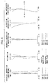
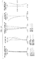
- Fig. 6 is a diagram of aberration curves of the wide-angle objective optical system of the present example.
- Lens data of the wide-angle objective optical system of Example 1 of the present invention is as follows.
- Lens Data Face No. r d Ne Vd Object face ⁇ 7.34 1. 1 ⁇ 0.2250 1.88815 40.76 2 0.5303 0.2400 1. 3 -3.2898 0.2250 1.64116 23.90 4 -22.5660 0.2217 1, 5 (Brightness diaphragm) ⁇ 0.0375 1. 6 1.5164 0.1967 1.53296 55.69 7 -1.2232 0.9242 1. 8 1.3092 0.7052 1.53296 55.69 9* -1.2062 0.1500 1. 10 -1.1260 0.2272 1.64116 23.90 11 2.0776 0.0375 1. 12 1.7475 0.8718 1.53296 55.69 13* -2.5172 0.9259 1. 14 ⁇ 0.5506 1.51825 64.14 15 ⁇ 0.0918 1. Image plane ⁇
- the wide-angle objective optical system of the present example which has an outer diameter of an end that is substantially same as the image height, is compact. Further, the wide-angle objective optical system achieves an angle of view of 137°.
- the lenses other than the first lens of the first lens group are adapted to characteristics of existing plastic optical materials with which injection molding can be performed. Thus, the manufacturing cost can be reduced to be low. Moreover, optical performance can be corrected preferably so that the wide-angle objective optical system is applicable to high-definition and high-pixel image pickup elements.
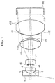
- Fig. 7 illustrates a configuration of a wide-angle objective optical system of Example 2 of the present invention.
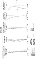
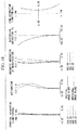
- Fig. 8 is a diagram of aberration curves of the wide-angle objective optical system of the present example.
- Lens data of the wide-angle objective optical system of Example 2 of the present invention is as follows.
- Lens Data Face No. r d Ne Vd Object face ⁇ 7.57 1. 1 ⁇ 0.2222 1.80811 46.57 2 0.4927 0.2475 1. 3 -3.4692 0.2168 1.53296 55.69 4 -7.8905 0.2535 1.
- 5 (Brightness diaphragm) ⁇ 0.0387 1. 6 1.5923 0.4206 1.53296 55.69 7 -1.2446 0.8759 1.
- 8 1.3493 0.8307 1.53296 55.69 9* -1.3500 0.1547 1. 10 -1.1851 0.2089 1.64116 23.90 11* 2.1985 0.0387 1. 12 1.9569 1.3150 1.53296 55.69 13* -2.4476 0.4477 1. 14 ⁇ 0.5415 1.51825 64.14 15 ⁇ 0.0947 1.
- Image plane ⁇
- the wide-angle objective optical system of the present example which has an outer diameter of an end that is substantially same as the image height, is compact. Further, the wide-angle objective optical system achieves a very wide angle of view of 160.8°.
- the lenses other than the first lens of the first lens group can be formed of a material adapted to characteristics of existing plastic optical materials with which injection molding can be performed. Thus, the manufacturing cost can be reduced to be low. Moreover, optical performance can be corrected preferably so that the wide-angle objective optical system is applicable to high-definition and high-pixel image pickup elements.
- Fig. 9 illustrates a configuration of a wide-angle objective optical system of Example 3 of the present invention.
- Fig. 10 is a diagram of aberration curves of the wide-angle objective optical system of the present example.
- Lens data of the wide-angle objective optical system of Example 3 of the present invention is as follows.
- Lens Data Face No. r d Ne Vd Object face ⁇ 7.71 1. 1 ⁇ 0.2363 1.88815 40.76 2 0.5431 0.2520 1. 3 -3.1744 0.2207 1.53296 55.69 4 -10.0626 0.2574 1.
- 5 (Brightness diaphragm) ⁇ 0.0394 1.
- 6 1.6617 0.4112 1.53296 55.69 7 -1.2271 0.8888 1.
- 8 1.3585 0.9015 1.53296 55.69
- Image plane ⁇
- the wide-angle objective optical system of the present example which has an outer diameter of an end that is substantially same as the image height, is compact. Further, the wide-angle objective optical system achieves a very wide angle of view of 164.0°.
- the lenses other than the first lens of the first lens group can be formed of a material adapted to characteristics of existing plastic optical materials with which injection molding can be performed. Thus, the manufacturing cost can be reduced to be low. Moreover, optical performance can be corrected preferably so that the wide-angle objective optical system is applicable to high-definition and high-pixel image pickup elements.
- Fig. 11 illustrates a configuration of a wide-angle objective optical system of Example 4 of the present invention.
- Fig. 12 is a diagram of aberration curves of the wide-angle objective optical system of the present example.
- Lens data of the wide-angle objective optical system of Example 4 of the present invention is as follows.
- Lens Data Face No. r d Ne Vd Object face ⁇ 7.26 1. 1 ⁇ 0.2214 1.88815 40.76 2 0.5302 0.2362 1. 3 -3.4490 0.2214 1.64116 23.90 4 -13.2109 0.2315 1.
- 5 (Brightness diaphragm) ⁇ 0.0369 1.
- 6 1.3615 0.2145 1.53296 55.69 7 -1.2179 0.9486 1.
- 8 1.2790 0.6072 1.53296 55.69 9* -1.3060 0.1476 1.
- 10 -1.4980 0.2527 1.85504 23.78 11 2.8365 0.0369 1.
- 12 1.9192 0.8580 1.53296 55.69 13* -2.3746 0.8169 1.
- Image plane ⁇
- the wide-angle objective optical system of the present example which has an outer diameter of an end that is substantially same as the image height, is compact. Further, the wide-angle objective optical system achieves a very wide angle of view of 164.0°.
- the lenses other than the first lens of the first lens group and the second lens of the second group can be formed of a material adapted to characteristics of existing plastic optical materials with which injection molding can be performed. Thus, the manufacturing cost can be reduced to be low.
- optical performance can be corrected preferably so that the wide-angle objective optical system is applicable to high-definition and high-pixel image pickup elements.
- Fig. 13 illustrates a configuration of a wide-angle objective optical system of Example 5 of the present invention.
- Fig. 14 is a diagram of aberration curves of the wide-angle objective optical system of the present example.
- Lens data of the wide-angle objective optical system of Example 5 of the present invention is as follows.
- Lens Data Face No. r d Ne Vd Object face ⁇ 8.18 1. 1 ⁇ 0.2505 1.88815 40.76 2 0.6109 0.2672 1. 3 -4.3397 0.2340 1.53296 55.69 4 -241.7170 0.3217 1.
- 5 (Brightness diaphragm) ⁇ 0.0418 1.
- 6 2.3344 0.3621 1.53296 55.69 7 -1.3748 0.8690 1.
- 8 1.4063 0.9028 1.53296 55.69 9* -1.4833 0.1670 1. 10 -1.2593 0.2255 1.64116 23.90 11* 2.3544 0.1086 1.
- the wide-angle objective optical system of the present example which has an outer diameter of an end that is less than 1.2 times of the image height, is compact. Further, the wide-angle objective optical system achieves a very wide angle of view of 164.0°.
- the lenses other than the first lens of the first group can be formed of a material adapted to characteristics of existing plastic optical materials with which injection molding can be performed. Thus, the manufacturing cost can be reduced to be low. Moreover, optical performance can be corrected preferably so that the wide-angle objective optical system is applicable to high-definition and high-pixel image pickup elements.
- Fig. 15 illustrates a configuration of a wide-angle objective optical system of Example 6 of the present invention.
- Fig. 16 is a diagram of aberration curves of the wide-angle objective optical system of the present example.
- Lens data of the wide-angle objective optical system of Example 6 of the present invention is as follows.
- 5 (Brightness ⁇ 0.0411 1. diaphragm) 6 2.3493 0.3634 1.53296 55.69 7 -1.3844 0.8988 1. 8 1.3918 0.8675 1.53296 55.69 9* -1.4475 0.1642 1.
- the wide-angle objective optical system of the present example which has an outer diameter of an end that is less than 1.2 times of the image height, is compact. Further, the wide-angle objective optical system achieves a very wide angle of view of 160.2°.
- the lenses other than the first lens of the first group can be formed of a material adapted to characteristics of existing plastic optical materials with which injection molding can be performed. Thus, the manufacturing cost can be reduced to be low. Moreover, optical performance can be corrected preferably so that the wide-angle objective optical system is applicable to high-definition and high-pixel image pickup elements.
- Fig. 17 illustrates a configuration of a wide-angle objective optical system of Example 7 of the present invention.
- Fig. 18 is a diagram of aberration curves of the wide-angle objective optical system of the present example.
- Lens data of the wide-angle objective optical system of Example 7 of the present invention is as follows.
- Lens Data Face No. r d Ne Vd Object face ⁇ 7.44 1. 1 ⁇ 0.2184 1.80811 46.57 2 0.4889 0.2433 1. 3 -4.4397 0.2130 1.53296 55.69 4 -4.7905 0.2596 1.
- 5 (Brightness diaphragm) ⁇ 0.0380 1.
- 6 1.9357 0.4322 1.53296 55.69 7 -1.1697 0.8118 1.
- 10 -1.1751 0.2053 1.64116 23.90 11 1.8701 1.2924 1.53296 55.69
- 12* -2.3764 0.4228 1. 13 ⁇ 0.5322 1.51825 64.14 14 ⁇ 0.0930 1.
- Image plane ⁇
- the wide-angle objective optical system of the present example which has an outer diameter of an end that is substantially same as the image height, is compact. Further, the wide-angle objective optical system achieves an angle of view of 140.6°.
- the lenses other than the first lens of the first lens group are adapted to characteristics of existing plastic optical materials with which injection molding can be performed. Thus, the manufacturing cost can be reduced to be low. Moreover, optical performance can be corrected preferably so that the wide-angle objective optical system is applicable to high-definition and high-pixel image pickup elements.
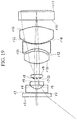
- Fig. 19 illustrates a configuration of a wide-angle objective optical system of Example 8 of the present invention.
- Fig. 20 is a diagram of aberration curves of the wide-angle objective optical system of the present example.
- Lens data of the wide-angle objective optical system of Example 8 of the present invention is as follows.
- Lens Data Face No. r d Ne Vd Object face ⁇ 6.71 1. 1 ⁇ 0.2058 1.53296 55.69 2 ⁇ 0.0420 1. 3 10.6871 0.2058 1.53296 55.69 4* 0.4072 0.2404 1. 5 -2.8467 0.2058 1.53296 55.69 6 -8.2032 0.1935 1.
- 8 1.4544 0.2047 1.53296 55.69 9 -1.5617 0.6498 1.
- 10 1.2805 0.7545 1.53296 55.69 11* -0.9639 0.1372 1.
- the wide-angle objective optical system of the present example which has an outer diameter of a parallel plate for protection of an end that is 1.5 times of the image height, is compact. Further, the wide-angle objective optical system achieves a wide angle of view of 103.8°. All lenses can be formed of a material adapted to characteristics of existing plastic optical materials with which injection molding can be performed. Thus, the manufacturing cost can be reduced to be low. Moreover, optical performance can be corrected preferably so that the wide-angle objective optical system is applicable to high-definition and high-pixel image pickup elements.
- the parallel plate for protection may be formed of optical glass, which is resistant to damage, instead of a plastic optical material.
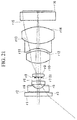
- Fig. 20 illustrates a configuration of a wide-angle objective optical system of Example 9 of the present invention.
- Fig. 21 is a diagram of aberration curves of the wide-angle objective optical system of the present example.
- Lens data of the wide-angle objective optical system of Example 9 of the present invention is as follows. ⁇ Table 25 ⁇ Lens Data Face No. r d Ne Vd Object face ⁇ 6.62 1. 1 ⁇ 0.2029 1.53296 55.69 2 ⁇ 0.0415 1. 3 11.9388 0.2029 1.53296 55.69 4* 0.3999 0.2384 1. 5 -2.7645 0.2029 1.53296 55.69 6 -8.2657 0.1932 1. STO ⁇ 0.0338 1. 8 1.3707 0.2038 1.53296 55.69 9 -1.5017 0.6234 1. 10 1.2580 0.7441 1.53296 55.69 11* -0.9491 0.1353 1. 12* -1.1132 0.2706 1.64116 23.90 13 1.5998 1.0147 1.53296 55.69 14* -1.8606 0.3854 1. 15 ⁇ 0.4966 1.51825 64.14 16 ⁇ 0.0828 1. Image plane ⁇
- the wide-angle objective optical system of the present example which has an outer diameter of a parallel plate for protection of an end that is less than 1.5 times of the image height, is compact. Further, the wide-angle objective optical system achieves a wide angle of view of 116.6°. All lenses can be formed of a material adapted to characteristics of existing plastic optical materials with which injection molding can be performed. Thus, the manufacturing cost can be reduced to be low. Moreover, optical performance can be corrected preferably so that the wide-angle objective optical system is applicable to high-definition and high-pixel image pickup elements.
- the parallel plate for protection may be formed of optical glass, which is resistant to damage, instead of a plastic optical material.
Landscapes
- Physics & Mathematics (AREA)
- Health & Medical Sciences (AREA)
- Life Sciences & Earth Sciences (AREA)
- Optics & Photonics (AREA)
- Surgery (AREA)
- General Physics & Mathematics (AREA)
- Heart & Thoracic Surgery (AREA)
- Biophysics (AREA)
- Pathology (AREA)
- Radiology & Medical Imaging (AREA)
- Veterinary Medicine (AREA)
- Engineering & Computer Science (AREA)
- Nuclear Medicine, Radiotherapy & Molecular Imaging (AREA)
- Animal Behavior & Ethology (AREA)
- Biomedical Technology (AREA)
- Molecular Biology (AREA)
- Medical Informatics (AREA)
- General Health & Medical Sciences (AREA)
- Public Health (AREA)
- Astronomy & Astrophysics (AREA)
- Lenses (AREA)
Abstract
Description
- The present invention relates to a wide-angle objective optical system that is compact and applicable to endoscopes and monitoring cameras, and more particularly, to a wide-angle objective optical system that has a 100 degree or more angle of view.
- Definition enhancement and increase in pixel value for solid state imaging elements such as CCD or CMOS sensors have been promoted recently. On the other hand, for objective lenses applicable to endoscopes and monitoring cameras, wider photographing ranges, that is, wider angles of view have been conventionally demanded. Further, since a channel for inserting illuminating optical systems and treatment instruments and an air/water supply nozzle need to be arranged at a distal end of an endoscope, reducing diameters of ends of objective lenses has been demanded. Also for monitoring cameras, reducing diameters of ends of lenses has been demanded for making the lenses inconspicuous.
- As such a wide-angle objective optical system, for example, each of
PTL 1 to PTL 3 discloses a wide-angle objective optical system including, in order from an object side, a first lens having negative refractive index, a second lens having negative refractive index, a brightness diaphragm and a third lens having positive refractive index. To achieve a smaller outer diameter of an end as well as a wider angle, in each of the objective optical systems, the first lens has negative refractive index and the brightness diaphragm is arranged as near an object as possible so that an entrance pupil is placed at a front side. - For such objective optical systems, reduction in manufacturing cost has also been demanded. In mobile phones or the like, lenses are manufactured in large amounts in a short time by an injection molding technique using a plastic optical material to bring about cost down.
- To achieve definition enhancement and increase in pixel value of a solid state imaging element, an aberration generated in an objective optical system needs to be further reduced. To achieve a wider angle, a chromatic aberration of magnification, which has a great influence on peripheral performance, particularly, needs to be reduced.
-
- {PTL 1} Japanese Unexamined Patent Application, Publication No.
Hei 10-20189 - {PTL 2} Japanese Unexamined Patent Application, Publication No.
Hei 10-197787 - {PTL 3} Japanese Unexamined Patent Application, Publication No.
Sho 61-162021 - However, in the objective optical system of
PTL 1, since refractive power arrangement in each lens causes reduction in the overall lens length, a large amount of glass materials having a high refractive index needs to be used. Thus, the manufacturing cost increases. In the objective optical system of PTL 2, the number of the included lenses is excessively small. Thus, imaging performance is insufficient for definition enhancement and a wider angle of view of a solid state imaging element. In the objective optical system of PTL 3, refractive power arrangement and shapes of the first lens and the second lens prevent the position of the entrance pupil from being placed at the front side. Thus, the outer diameter of the end becomes large. - The present invention has been made in view of the aforementioned situations. The object of the present invention is to provide a wide-angle objective optical system that enables excellent aberration correction, suitability for high-definition and high-pixel solid state imaging elements, a small outer diameter of an end and reduction in manufacturing cost.
- To achieve the aforementioned object, the present invention provides the following solutions.
- An aspect of the present invention is a wide-angle objective optical system comprising, in order from an object side to an image side: a first lens group; and a second lens group having positive refractive power, wherein the first lens group comprises, in order from the object side to the image side: a first lens having negative refractive power; a second lens having a concave face as an object-side face and having negative refractive power; a brightness diaphragm; and a third lens having positive refractive power, and the following condition expressions are satisfied:


- In the present aspect, since the wide-angle objective optical system has two separate lens groups: the first lens group and the second lens group having positive refractive power, aberrations of the respective lens groups can be corrected independently and loads of the aberration correction can be distributed between the two lens groups in a well-balanced manner. Consequently, a high-performance objective optical system can be obtained with the smaller number of the lenses.
- Further, since the first lens group comprises, in order from the object side to the image side: the first lens having negative refractive power; the second lens having a concave face as the object-side face and having negative refractive power; the brightness diaphragm; and the third lens having positive refractive power, a position of an entrance pupil can be placed as near an object as possible. Thus, an outer diameter of an end of the objective optical system can be reduced.
- In this way, the present aspect enables excellent aberration correction, suitability for high-definition and high-pixel solid state imaging elements, and further, a small outer diameter of the end, and reduction in manufacturing cost.
- Furthermore, in the aforementioned aspect, it is preferable that the following condition expression is satisfied:

- By this configuration, an off-axis aberration can be appropriately corrected, and further, the diameter of the end can be reduced.
- Moreover, in the aforementioned aspect, it is preferable that the second lens group includes, in order from the object side to the image side, a fourth lens having positive refractive power, a fifth lens having negative refractive power and a sixth lens having positive refractive power.
- By this configuration, a color of magnification, an astigmatic difference and a field curvature can be appropriately corrected with the small number of the included lenses and an optical member having a low refractive index. Thus, while high performance is achieved, the manufacturing cost can be reduced.
- Furthermore, in the aforementioned aspect, it is preferable that the second lens group includes, in order from the object side to the image side, a fourth lens having positive refractive power, a fifth lens having negative refractive power, a sixth lens having positive refractive power and a seventh lens having positive refractive power.
- By this configuration, a color of magnification, an astigmatic difference and a field curvature can be appropriately corrected with an optical member having a low refractive index. Thus, while high performance is achieved, the manufacturing cost can be reduced.
- Moreover, in the aforementioned aspect, it is preferable the following condition expression is satisfied:

- By this configuration, an off-axis aberration such as a field curvature, an astigmatic difference, a coma aberration and a chromatic aberration of magnification can be appropriately corrected.
- Furthermore, in the aforementioned aspect, it is preferable that the following condition expression is satisfied:

- By this configuration, an off-axis aberration such as a field curvature, an astigmatic difference, a coma aberration and a chromatic aberration of magnification can be appropriately corrected.
- The present invention provides an effect that enables excellent aberration correction, suitability for high-definition and high-pixel solid state imaging elements, and further, a small outer diameter of an end and reduction in manufacturing cost.
-
- {
Fig. 1} Fig. 1 is a sectional view of an overall configuration of a wide-angle objective optical system of an embodiment of the present invention. - {
Fig. 2} Fig. 2 is an explanatory diagram of an afocal arrangement. - {
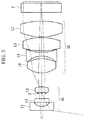
Fig. 3} Fig. 3 is a sectional view of an overall configuration of a wide-angle objective optical system in another example of the embodiment of the present invention. - {
Fig. 4} Fig. 4 is a sectional view of an overall configuration of a wide-angle objective optical system in still another example of the embodiment of the present invention. - {
Fig. 5} Fig. 5 is a sectional view of an overall configuration of a wide-angle objective optical system of Example 1 of the present invention. - {
Fig. 6} Fig. 6 is a diagram of aberration curves of the wide-angle objective optical system ofFig. 5 . - {
Fig. 7} Fig. 7 is a sectional view of an overall configuration of a wide-angle objective optical system of Example 2 of the present invention. - {
Fig. 8} Fig. 8 is a diagram of aberration curves of the wide-angle objective optical system ofFig. 7 . - {
Fig. 9} Fig. 9 is a sectional view of an overall configuration of a wide-angle objective optical system of Example 3 of the present invention. - {
Fig. 10} Fig. 10 is a diagram of aberration curves of the wide-angle objective optical system ofFig. 9 . - {
Fig. 11} Fig. 11 is a sectional view of an overall configuration of a wide-angle objective optical system of Example 4 of the present invention. - {
Fig. 12} Fig. 12 is a diagram of aberration curves of the wide-angle objective optical system ofFig. 11 . - {
Fig. 13} Fig. 13 is a sectional view of an overall configuration of a wide-angle objective optical system of Example 5 of the present invention. - {
Fig. 14} Fig. 14 is a diagram of aberration curves of the wide-angle objective optical system ofFig. 13 . - {
Fig. 15} Fig. 15 is a sectional view of an overall configuration of a wide-angle objective optical system of Example 6 of the present invention. - {
Fig. 16} Fig. 16 is a diagram of aberration curves of the wide-angle objective optical system ofFig. 15 . - {
Fig. 17} Fig. 17 is a sectional view of an overall configuration of a wide-angle objective optical system of Example 7 of the present invention. - {
Fig. 18} Fig. 18 is a diagram of aberration curves of the wide-angle objective optical system ofFig. 17 . - {
Fig. 19} Fig. 19 is a sectional view of an overall configuration of a wide-angle objective optical system of Example 8 of the present invention. - {
Fig. 20} Fig. 20 is a diagram of aberration curves of the wide-angle objective optical system ofFig. 19 . - {
Fig. 21} Fig. 21 is a sectional view of an overall configuration of a wide-angle objective optical system of Example 9 of the present invention. - {
Fig. 22} Fig. 22 is a diagram of aberration curves of the wide-angle objective optical system ofFig. 21 . - Hereinafter, descriptions will be given of a wide-angle objective optical system of an embodiment of the present invention with reference to the drawings.
-
Fig. 1 illustrates a sectional view of an overall configuration of the wide-angle objective optical system of the present embodiment. As illustrated inFig. 1 , the wide-angle objective optical system includes, in order from an object side to an image side, a first lens group G1 and a second lens group G2 having positive refractive power (hereinafter referred to as "positive" simply). - The first lens group G1 includes, in order from the object side to the image side, a first lens L1 having negative refractive power (hereinafter referred to as "negative" simply), a negative second lens L2 having a concave face as an object-side face, a brightness diaphragm S and a positive third lens L3.
- The second lens group G2 includes, in order from the object side, a positive fourth lens L4, a negative fifth lens L5 and a positive sixth lens L6.
- An image pickup element (not illustrated) is arranged in the vicinity of an image plane of the wide-angle objective optical system. The image pickup element is included in the wide-angle objective optical system and an image pickup optical system. To the image pickup element, a parallel plate F that protects an imaging area is attached.
- The wide-angle objective optical system is divided into two groups: the first lens group G1 and the second lens group G2 having positive refractive power, as in the present embodiment, and the first lens group is further divided into a negative front group G1n and a positive rear group G1p in an afocal arrangement. Consequently, aberrations of the wide-angle objective optical system are corrected with high performance and the number of the included lenses is reduced. Thus, such a low refractive index can be achieved that allows usage of a plastic optical material, and a wide angle can also be achieved.
- Afocal arrangement herein means, as illustrated in
Fig. 2 , that a focal distance f2 of the second lens group, a focal distance fg1n and a focal distance fg1p of the front group and the rear group, respectively, included in the first lens group G1 and a principal point interval Dnp between G1n and G1p substantially satisfy the following expression (A):
- At that time, an entire focal distance f approximates the following expression (B):

- The value of "-fg1n/fg1p" is referred to as an afocal magnification.
- Such afocal arrangement enables correction of aberrations of the first lens group G1 and the second lens group G2 separately. Further, loads of the aberration correction can be distributed between the first lens group G1 and the second lens group G2 in a well-balanced manner. Consequently, a high-performance objective optical system can be achieved with the small number of the lenses.
- The wide-angle objective optical system satisfies the following condition expressions (1) and (2).


- The condition expression (1) is a condition to achieve an afocal arrangement. If f/f1 is equal to or lower than the lower limit of -0.5, stronger positive refractive power is required for the second lens group G2, which makes the aberration correction difficult. If f/f1 is equal to or higher than the upper limit of 0.5, the load of the aberration correction in the first lens group increases, which deteriorates the performance.
- The condition expression (2) defines the refractive power of the second lens group G2. If f/f2 is equal to or lower than the lower limit of 0.3, the smaller afocal magnification is required for the first lens group G1, which increases the load of the aberration correction in the first lens group G1, and further, as the focal distance of the second lens group G2 increases, the overall length increases. If f/f2 is equal to or higher than the upper limit of 0.7, the load of the aberration correction in the second lens group G2 becomes excessively large, which deteriorates the performance.
- To make an outer diameter of the end small, a position of an entrance pupil needs to be placed as near an object as possible. Thus, the first lens group G1 is configured by the negative first lens L1, the negative second lens L2 having a concave face as the object-side face, the brightness diaphragm S and the positive third lens L3, in order from the object side. Placing the brightness diaphragm S before the positive third lens L3 makes the position of the entrance pupil as near the object as possible.
- Moreover, the stronger refractive power of the third lens L3 enables a smaller space between the second lens L2 and the third lens L3 to place the position of the entrance pupil at the front side, with keeping the afocal magnification same. However, synthetic refractive power of the first lens L1 and the second lens L2 increases simultaneously. Thus, to correct an aberration, negative refractive power is distributed into the first lens L1 and the second lens L2.
- Furthermore, the second lens L2 has a concave face as the object-side face and has negative refractive power. Thus, the rear-side principal point position of the synthetic refractive power of the first lens L1 and the second lens L2 can be placed forward, which allows the afocal magnification to be small.
- The wide-angle objective optical system satisfies the following condition expression:

- In the condition expression (3), if D/f is equal to or lower than the lower limit of 0.8, an off-axis aberration (field curvature, astigmatic difference, coma aberration) generated in the first lens group G1 is difficult to be corrected by the second lens group G2 formed of glass having a low refractive index, which prevents achievement of a wider angle in the wide-angle objective optical system. The reason is that the narrower space makes an off-axis ray pass the second lens group G2 at a lower height, which prevents aberration correction independent of an on-axis ray.
- Although strengthening the refractive power of the second lens group G2 and lowering the height of the ray relatively are conceivable, the second lens group G2 needs to use glass having a high refractive index. In contrast, if D/f is equal to or higher than the upper limit of 1.2, the distance from the second lens group G2 excessively increases, a height at which an off-axis ray enters the second lens group G2 becomes higher. As a result, the outer diameter of the second lens group G2 becomes large and an aberration is generated to bring about performance deterioration. The upper limit is further preferably a value lower than 1.0, at which the size and the performance are well-balanced.
- If the lower limit is changed from 0.8 to 0.6 in the condition expression (3), the wide-angle objective optical system, including the first lens L1 of the first lens group G1, can be formed of a plastic optical material which has a low refractive index and is suitable for injection molding. The reason is that the afocal magnification of the first lens group G1 can be large and the height at which an off-axis ray passes the second lens group G2 can be held.
- The wide-angle objective optical system satisfies the following condition expression:

- If f/f13 is equal to or lower than the lower limit of 0.5 in the condition expression (4), the space between the second lens L2 and the third lens L3 of the first lens group G1 becomes wider in order to secure the afocal magnification. Thus, the outer diameter of the end becomes large. If f/f13 is equal to or higher than the upper limit of 0.9, the refractive power of the first lens L1 and the third lens L3 of the first lens group G1 is excessively strong. Thus, an off-axis aberration (field curvature, astigmatic difference, coma aberration, chromatic aberration of magnification) is difficult to be corrected.
- The wide-angle objective optical system further satisfies the following condition expression:

- If f/f12 is equal to or lower than the lower limit of - 0.3 in the condition expression (5), the space between the second lens L2 and the third lens L3 of the first lens group G1 becomes wider in order to secure the afocal magnification. Thus, the outer diameter of the end becomes large. If f/f12 is equal to or higher than the upper limit of 0.0, the refractive power of the first lens L1 of the first lens group G1 is excessively strong. Thus, an off-axis aberration (field curvature, astigmatic difference, coma aberration, chromatic aberration of magnification) is difficult to be corrected.
- In the present embodiment, as described above, the second lens group G2 is a triplet configuration including the positive fourth lens L4, the negative fifth lens L5 and the positive sixth lens L6, which are arranged in order from the object side. Accordingly, a color of magnification, an astigmatic difference and a field curvature can be appropriately corrected with the small number of the included lenses and the optical member having a low refractive index.
- The second lens group G2 is not limited to the aforementioned configuration but, for example, may have a quadruplet configuration in which the fourth lens L4 having positive refractive power, the fifth lens L5 having negative refractive power, the sixth lens L6 having positive refractive power and a seventh lens L7 having positive refractive power are included, as illustrated in
Fig. 3 , that is, a lens having positive refractive power is added to a triplet. This configuration can reduce loads to the lenses having positive refractive power of the second lens group. Consequently, a color of magnification, an astigmatic difference and a field curvature can be appropriately corrected with the optical member having a low refractive index. - If, as illustrated in
Fig. 4 , the second lens group G2 includes a cemented lens CL1 that is formed by cementing the fifth lens 5 and the sixth lens 6, a color of magnification is corrected more appropriately although an angle of view is a little narrower than that in the aforementioned embodiment. - In the present embodiment, as described above, the wide-angle objective optical system has a wider angle of view, can correct aberrations appropriately, is suitable even for high-definition and high-pixel solid state imaging elements, and can reduce the diameter. The number of the lenses included in the wide-angle objective optical system can be reduced so that the overall length can be decreased. Also, the manufacturing cost can be reduced.
- Next, descriptions will be given of Examples 1 to 9 of the wide-angle objective optical system of the aforementioned embodiment with reference to
Fig. 5 to Fig. 22 . In lens data shown in the Examples, r is a curvature radius (unit: mm), d is a face space (mm), Ne is a refractive index relative to a line e, and Vd is an Abbe number relative to a line d. - Regarding an aspherical face, "*" is added to its face number in the lens data. A paraxial curvature radius r, a conic constant K, an aspheric coefficient Ai (i = 2, 4, 6, 8, and 10), which are expressed by the following expression, are shown in the aspherical face data. In the following expression, an optical axis direction is z and a direction perpendicular to the optical axis is y.

-
Fig. 5 illustrates a configuration of a wide-angle objective optical system of Example 1 of the present invention.Fig. 6 is a diagram of aberration curves of the wide-angle objective optical system of the present example. - Lens data of the wide-angle objective optical system of Example 1 of the present invention is as follows.
Lens Data Face No. r d Ne Vd Object face ∞ 7.34 1. 1 ∞ 0.2250 1.88815 40.76 2 0.5303 0.2400 1. 3 -3.2898 0.2250 1.64116 23.90 4 -22.5660 0.2217 1, 5 (Brightness diaphragm) ∞ 0.0375 1. 6 1.5164 0.1967 1.53296 55.69 7 -1.2232 0.9242 1. 8 1.3092 0.7052 1.53296 55.69 9* -1.2062 0.1500 1. 10 -1.1260 0.2272 1.64116 23.90 11 2.0776 0.0375 1. 12 1.7475 0.8718 1.53296 55.69 13* -2.5172 0.9259 1. 14 ∞ 0.5506 1.51825 64.14 15 ∞ 0.0918 1. Image plane ∞ -
- 9th face
- r=-1.2062
- K=-0.3682
- A2=0.0000E+00
- A4=2.5578E-01
- A6=1.8699E-01
- A8=-4.0304E-01
- 13th face
- r=-2.5172
- K=-0.7009
- A2=0.0000E+00
- A4=-5.6576E-02
- A6=3.1115E-02
- A8=3.5770E-02
- A10=-7.2866E-05
-
- Focal distance 1.0
- Image height 1.01
- Fno. 7.03
- Effective Fno. 7.15
- Objective distance 7.34
- Half angle of view 68.5°
- Distortion aberration -59.6%
- The wide-angle objective optical system of the present example, which has an outer diameter of an end that is substantially same as the image height, is compact. Further, the wide-angle objective optical system achieves an angle of view of 137°. The lenses other than the first lens of the first lens group are adapted to characteristics of existing plastic optical materials with which injection molding can be performed. Thus, the manufacturing cost can be reduced to be low. Moreover, optical performance can be corrected preferably so that the wide-angle objective optical system is applicable to high-definition and high-pixel image pickup elements.
-
Fig. 7 illustrates a configuration of a wide-angle objective optical system of Example 2 of the present invention.Fig. 8 is a diagram of aberration curves of the wide-angle objective optical system of the present example. - Lens data of the wide-angle objective optical system of Example 2 of the present invention is as follows.
Lens Data Face No. r d Ne Vd Object face ∞ 7.57 1. 1 ∞ 0.2222 1.80811 46.57 2 0.4927 0.2475 1. 3 -3.4692 0.2168 1.53296 55.69 4 -7.8905 0.2535 1. 5 (Brightness diaphragm) ∞ 0.0387 1. 6 1.5923 0.4206 1.53296 55.69 7 -1.2446 0.8759 1. 8 1.3493 0.8307 1.53296 55.69 9* -1.3500 0.1547 1. 10 -1.1851 0.2089 1.64116 23.90 11* 2.1985 0.0387 1. 12 1.9569 1.3150 1.53296 55.69 13* -2.4476 0.4477 1. 14 ∞ 0.5415 1.51825 64.14 15 ∞ 0.0947 1. Image plane ∞ -
- 9th face
- r=-1.3500
- K=-0.3596
- A2=0.0000E+00
- A4=2.0711E-01
- A6=1.8713E-01
- A8=-2.5548E-01
- 11th face
- r=2.1985
- K=-0.0656
- A2=0.0000E+00
- A4=8.8749E-03
- A6=1.8169E-03
- A8=4.5301E-04
- 13th face
- r=-2.4476
- K=-0.6886
- A2=0.0000E+00
- A4=-7.6842E-02
- A6=6.5255E-03
- A8=1.2701E-02
- A10=2.1695E-03
-
- Focal distance 1.0
- Image height 1.04
- Fno. 7.03
- Effective Fno. 7.12
- Objective distance 7.57
- Half angle of view 80.4°
- Distortion aberration -81.8%
- The wide-angle objective optical system of the present example, which has an outer diameter of an end that is substantially same as the image height, is compact. Further, the wide-angle objective optical system achieves a very wide angle of view of 160.8°. The lenses other than the first lens of the first lens group can be formed of a material adapted to characteristics of existing plastic optical materials with which injection molding can be performed. Thus, the manufacturing cost can be reduced to be low. Moreover, optical performance can be corrected preferably so that the wide-angle objective optical system is applicable to high-definition and high-pixel image pickup elements.
-
Fig. 9 illustrates a configuration of a wide-angle objective optical system of Example 3 of the present invention.Fig. 10 is a diagram of aberration curves of the wide-angle objective optical system of the present example. - Lens data of the wide-angle objective optical system of Example 3 of the present invention is as follows.
Lens Data Face No. r d Ne Vd Object face ∞ 7.71 1. 1 ∞ 0.2363 1.88815 40.76 2 0.5431 0.2520 1. 3 -3.1744 0.2207 1.53296 55.69 4 -10.0626 0.2574 1. 5 (Brightness diaphragm) ∞ 0.0394 1. 6 1.6617 0.4112 1.53296 55.69 7 -1.2271 0.8888 1. 8 1.3585 0.9015 1.53296 55.69 9* -1.3881 0.1575 1. 10 -1.2238 0.2126 1.64116 23.90 11* 2.2871 0.0394 1. 12 2.0062 1.3388 1.53296 55.69 13* -2.5256 0.4396 1. 14 ∞ 0.5513 1.51825 64.14 15 ∞ 0.0964 1. Image plane ∞ -
- 9th face
- r=-1.3881
- K=-0.3653
- A2=0.0000E+00
- A4=2.1119E-01
- A6=1.7193E-01
- A8=-2.1072E-01
- 11th face
- r=2.2871
- K=-0.0522
- A2=0.0000E+00
- A4=2.1972E-03
- A6=1.5395E-03
- A8=-2.4528E-03
- 13th face
- r=-2.5256
- K=-0.6925
- A2=0.0000E+00
- A4=-6.7290E-02
- A6=8.1438E-03
- A8=1.6600E-02
- A10=-7.1607E-04
-
- Focal distance 1.0
- Image height 1.06
- Fno. 6.86
- Effective Fno. 6.94
- Objective distance 7.71
- Half angle of view 82.0°
- Distortion aberration -84.6%
- The wide-angle objective optical system of the present example, which has an outer diameter of an end that is substantially same as the image height, is compact. Further, the wide-angle objective optical system achieves a very wide angle of view of 164.0°. The lenses other than the first lens of the first lens group can be formed of a material adapted to characteristics of existing plastic optical materials with which injection molding can be performed. Thus, the manufacturing cost can be reduced to be low. Moreover, optical performance can be corrected preferably so that the wide-angle objective optical system is applicable to high-definition and high-pixel image pickup elements.
-
Fig. 11 illustrates a configuration of a wide-angle objective optical system of Example 4 of the present invention.Fig. 12 is a diagram of aberration curves of the wide-angle objective optical system of the present example. - Lens data of the wide-angle objective optical system of Example 4 of the present invention is as follows.
Lens Data Face No. r d Ne Vd Object face ∞ 7.26 1. 1 ∞ 0.2214 1.88815 40.76 2 0.5302 0.2362 1. 3 -3.4490 0.2214 1.64116 23.90 4 -13.2109 0.2315 1. 5 (Brightness diaphragm) ∞ 0.0369 1. 6 1.3615 0.2145 1.53296 55.69 7 -1.2179 0.9486 1. 8 1.2790 0.6072 1.53296 55.69 9* -1.3060 0.1476 1. 10 -1.4980 0.2527 1.85504 23.78 11 2.8365 0.0369 1. 12 1.9192 0.8580 1.53296 55.69 13* -2.3746 0.8169 1. 14 ∞ 0.5419 1.51825 64.14 15 ∞ 0.0903 1. Image plane ∞ -
- 9th face
- r=-1.3060
- K=-0.3864
- A2=0.0000E+00
- A4=3.1029E-01
- A6=2.1928E-01
- A8=-3.2078E-01
- 13th face
- r=-2.3746
- K=-0.6988
- A2=0.0000E+00
- A4=-6.1785E-02
- A6=3.8835E-03
- A8=3.8809E-02
- A10=-1.3094E-03
-
- Focal distance 1.0
- Image height 0.993
- Fno. 7.12
- Effective Fno. 7.20
- Objective distance 7.26
- Half angle of view 69.0°
- Distortion aberration -61.4%
- The wide-angle objective optical system of the present example, which has an outer diameter of an end that is substantially same as the image height, is compact. Further, the wide-angle objective optical system achieves a very wide angle of view of 164.0°. The lenses other than the first lens of the first lens group and the second lens of the second group can be formed of a material adapted to characteristics of existing plastic optical materials with which injection molding can be performed. Thus, the manufacturing cost can be reduced to be low. Moreover, optical performance can be corrected preferably so that the wide-angle objective optical system is applicable to high-definition and high-pixel image pickup elements.
-
Fig. 13 illustrates a configuration of a wide-angle objective optical system of Example 5 of the present invention.Fig. 14 is a diagram of aberration curves of the wide-angle objective optical system of the present example. - Lens data of the wide-angle objective optical system of Example 5 of the present invention is as follows.
Lens Data Face No. r d Ne Vd Object face ∞ 8.18 1. 1 ∞ 0.2505 1.88815 40.76 2 0.6109 0.2672 1. 3 -4.3397 0.2340 1.53296 55.69 4 -241.7170 0.3217 1. 5 (Brightness diaphragm) ∞ 0.0418 1. 6 2.3344 0.3621 1.53296 55.69 7 -1.3748 0.8690 1. 8 1.4063 0.9028 1.53296 55.69 9* -1.4833 0.1670 1. 10 -1.2593 0.2255 1.64116 23.90 11* 2.3544 0.1086 1. 12 4.1849 0.8351 1.53296 55.69 13 -3.3589 0.0418 1. 14 3.3680 1.0022 1.53296 55.69 15* -4.1540 0.5489 1. 16 ∞ 0.5846 1.51825 64.14 17 ∞ 0.1022 1. Image plane ∞ -
- 9th face
- r=-1.4833
- K=-0.3350
- A2=0.0000E+00
- A4=1.4162E-01
- A6=9.2723E-02
- A8=-1.6871E-01
- 11th face
- r=2.3544
- K= -0.1943
- A2=0.0000E+00
- A4=6.2544E-03
- A6=2.7560E-03
- A8=4.5632E-03
- 15th face
- r=-4.1540
- K=-0.6724
- A2=0.0000E+00
- A4=-3.1750E-03
- A6=-1.3999E-03
- A8=1.1768E-03
- A10=9.6393E-04
-
- Focal distance 1.0
- Image height 1.12
- Fno. 6.51
- Effective Fno. 6.50
- Objective distance 8.18
- Half angle of view 82.0°
- Distortion aberration -83.4%
- The wide-angle objective optical system of the present example, which has an outer diameter of an end that is less than 1.2 times of the image height, is compact. Further, the wide-angle objective optical system achieves a very wide angle of view of 164.0°. The lenses other than the first lens of the first group can be formed of a material adapted to characteristics of existing plastic optical materials with which injection molding can be performed. Thus, the manufacturing cost can be reduced to be low. Moreover, optical performance can be corrected preferably so that the wide-angle objective optical system is applicable to high-definition and high-pixel image pickup elements.
-
Fig. 15 illustrates a configuration of a wide-angle objective optical system of Example 6 of the present invention.Fig. 16 is a diagram of aberration curves of the wide-angle objective optical system of the present example. - Lens data of the wide-angle objective optical system of Example 6 of the present invention is as follows.
Lens Data Face No. r d Ne Vd Object face ∞ 8.04 1. 1 ∞ 0.2359 1.80811 46.57 2 0.5554 0.2628 1. 3 -4.7506 0.2301 1.53296 55.69 4 -14.7055 0.3138 1. 5 (Brightness ∞ 0.0411 1. diaphragm) 6 2.3493 0.3634 1.53296 55.69 7 -1.3844 0.8988 1. 8 1.3918 0.8675 1.53296 55.69 9* -1.4475 0.1642 1. 10 -1.2200 0.2217 1.64116 23.90 11* 2.2838 0.1067 1. 12 3.9162 0.8211 1.53296 55.69 13* -3.2321 0.0411 1. 14 3.3038 0.9853 1.53296 55.69 15* -4.0534 0.5094 1. 16 ∞ 0.5748 1.51825 64.14 17 ∞ 0.1005 1. Image plane ∞ -
- 9th face
- r=-1.4475
- K=-0.3267
- A2=0.0000E+00
- A4=1.3199E-01
- A6=1.2211E-01
- A8=-2.0728E-01
- 11th face
- r=2.2838
- K=-0.1994
- A2=0.0000E+00
- A4=5.7995E-04
- A6=-1.1190E-04
- A8=9.0082E-03
- 13th face
- r=-3.2321
- K=0.0000
- A2=0.0000E+00
- A4=1.0619E-03
- A6=-8.9082E-04
- A8=2.4576E-05
- A10=9.9123E-04
- 15th face
- r=-4.0534
- K=-0.6719
- A2=0.0000E+00
- A4=-7.4185E-03
- A6=-7.6408E-04
- A8=1.8193E-03
- A10=4.1008E-04
-
- Focal distance 1.0
- Image height 1.11
- Fno. 7.09
- Effective Fno. 7.06
- Objective distance 8.04
- Half angle of view 80.1°
- Distortion aberration -79.7%
- The wide-angle objective optical system of the present example, which has an outer diameter of an end that is less than 1.2 times of the image height, is compact. Further, the wide-angle objective optical system achieves a very wide angle of view of 160.2°. The lenses other than the first lens of the first group can be formed of a material adapted to characteristics of existing plastic optical materials with which injection molding can be performed. Thus, the manufacturing cost can be reduced to be low. Moreover, optical performance can be corrected preferably so that the wide-angle objective optical system is applicable to high-definition and high-pixel image pickup elements.
-
Fig. 17 illustrates a configuration of a wide-angle objective optical system of Example 7 of the present invention.Fig. 18 is a diagram of aberration curves of the wide-angle objective optical system of the present example. - Lens data of the wide-angle objective optical system of Example 7 of the present invention is as follows.
Lens Data Face No. r d Ne Vd Object face ∞ 7.44 1. 1 ∞ 0.2184 1.80811 46.57 2 0.4889 0.2433 1. 3 -4.4397 0.2130 1.53296 55.69 4 -4.7905 0.2596 1. 5 (Brightness diaphragm) ∞ 0.0380 1. 6 1.9357 0.4322 1.53296 55.69 7 -1.1697 0.8118 1. 8 1.3220 0.8349 1.53296 55.69 9* -1.3119 0.1520 1. 10 -1.1751 0.2053 1.64116 23.90 11 1.8701 1.2924 1.53296 55.69 12* -2.3764 0.4228 1. 13 ∞ 0.5322 1.51825 64.14 14 ∞ 0.0930 1. Image plane ∞ -
- 9th face
- r=-1.3119
- K=-0.3507
- A2=0.0000E+00
- A4=2.2698E-01
- A6=1.7326E-01
- A8=-2.8028E-01
- 12th face
- r=-2.3764
- K=-0.6737
- A2=0.0000E+00
- A4=-8.7267E-02
- A6=1.1711E-02
- A8=3.3688E-02
- A10=-1.3511E-02
-
- Focal distance 1.0
- Image height 1.02
- Fno. 6.91
- Effective Fno. 7.20
- Objective distance 7.44
- Half angle of view 70.3°
- Distortion aberration -62.7%
- The wide-angle objective optical system of the present example, which has an outer diameter of an end that is substantially same as the image height, is compact. Further, the wide-angle objective optical system achieves an angle of view of 140.6°. The lenses other than the first lens of the first lens group are adapted to characteristics of existing plastic optical materials with which injection molding can be performed. Thus, the manufacturing cost can be reduced to be low. Moreover, optical performance can be corrected preferably so that the wide-angle objective optical system is applicable to high-definition and high-pixel image pickup elements.
-
Fig. 19 illustrates a configuration of a wide-angle objective optical system of Example 8 of the present invention.Fig. 20 is a diagram of aberration curves of the wide-angle objective optical system of the present example. - Lens data of the wide-angle objective optical system of Example 8 of the present invention is as follows.
Lens Data Face No. r d Ne Vd Object face ∞ 6.71 1. 1 ∞ 0.2058 1.53296 55.69 2 ∞ 0.0420 1. 3 10.6871 0.2058 1.53296 55.69 4* 0.4072 0.2404 1. 5 -2.8467 0.2058 1.53296 55.69 6 -8.2032 0.1935 1. 7 (Brightness diaphragm) ∞ 0.0343 1. 8 1.4544 0.2047 1.53296 55.69 9 -1.5617 0.6498 1. 10 1.2805 0.7545 1.53296 55.69 11* -0.9639 0.1372 1. 12 -1.1255 0.2744 1.64116 23.90 13 1.8786 0.0343 1. 14 1.6322 1.0289 1.53296 55.69 15* -1.9349 0.3990 1. 16 ∞ 0.5036 1.51825 64.14 17 ∞ 0.0839 1. Image plane ∞ -
- 4th face
- r=0.4072
- K=-0.5908
- A2=0.0000E+00
- A4=1.4061E+00
- A6=3.3904E-01
- A8=-1.8113E+00
- 11th face
- r=-0.9639
- K=-0.3711
- A2=0.0000E+00
- A4=3.4673E-01
- A6=7.5552E-01
- A8=-1.2819E+00
- 15th face
- r=-1.9349
- K=-0.7593
- A2=0.0000E+00
- A4=1.7180E-03
- A6=-1.8526E-01
- A8=2.5126E-O1
- A10=-1.9675E-02
-
- Focal distance 1.0
- Image height 0.923
- Fno. 6.83
- EffectiveFno. 6.93
- Objective distance 6.71
- Half angle of view 51.9°
- Distortion aberration -27.0%
- The wide-angle objective optical system of the present example, which has an outer diameter of a parallel plate for protection of an end that is 1.5 times of the image height, is compact. Further, the wide-angle objective optical system achieves a wide angle of view of 103.8°. All lenses can be formed of a material adapted to characteristics of existing plastic optical materials with which injection molding can be performed. Thus, the manufacturing cost can be reduced to be low. Moreover, optical performance can be corrected preferably so that the wide-angle objective optical system is applicable to high-definition and high-pixel image pickup elements. The parallel plate for protection may be formed of optical glass, which is resistant to damage, instead of a plastic optical material.
-
Fig. 20 illustrates a configuration of a wide-angle objective optical system of Example 9 of the present invention.Fig. 21 is a diagram of aberration curves of the wide-angle objective optical system of the present example. - Lens data of the wide-angle objective optical system of Example 9 of the present invention is as follows.
{Table 25} Lens Data Face No. r d Ne Vd Object face ∞ 6.62 1. 1 ∞ 0.2029 1.53296 55.69 2 ∞ 0.0415 1. 3 11.9388 0.2029 1.53296 55.69 4* 0.3999 0.2384 1. 5 -2.7645 0.2029 1.53296 55.69 6 -8.2657 0.1932 1. STO ∞ 0.0338 1. 8 1.3707 0.2038 1.53296 55.69 9 -1.5017 0.6234 1. 10 1.2580 0.7441 1.53296 55.69 11* -0.9491 0.1353 1. 12* -1.1132 0.2706 1.64116 23.90 13 1.5998 1.0147 1.53296 55.69 14* -1.8606 0.3854 1. 15 ∞ 0.4966 1.51825 64.14 16 ∞ 0.0828 1. Image plane ∞ -
- 4th face
- r=0.3999
- K=-0.6259
- A2=0.0000E+00
- A4=1.1956E+00
- A6=1.4816E+00
- A8=7.0716E+00
- 11th face
- r=-0.9491
- K=-0.3856
- A2=0.0000E+00
- A4=4.1595E-01
- A6=7.1883E-01
- A8=-1.2321E+00
- 12th face
- r=-1.1132
- K=0.0303
- A2=0.0000E+00
- A4=-3.6151E-05
- A6=4.5121E-05
- A8=-1.5651E-03
- 14th face
- r=-1.8606
- K=-0.7525
- A2=0.0000E+00
- A4=5.4669E-03
- A6=-2.4071E-01
- A8=2.0911E-01
- A10=3.2784E-02
-
- Focal distance 1.0
- Image height 0.910
- Fno. 6.97
- EffectiveFno. 7.11
- Objective distance 6.62
- Half angle of view 58.3°
- Distortion aberration -24.3%
- The wide-angle objective optical system of the present example, which has an outer diameter of a parallel plate for protection of an end that is less than 1.5 times of the image height, is compact. Further, the wide-angle objective optical system achieves a wide angle of view of 116.6°. All lenses can be formed of a material adapted to characteristics of existing plastic optical materials with which injection molding can be performed. Thus, the manufacturing cost can be reduced to be low. Moreover, optical performance can be corrected preferably so that the wide-angle objective optical system is applicable to high-definition and high-pixel image pickup elements. The parallel plate for protection may be formed of optical glass, which is resistant to damage, instead of a plastic optical material.
- Numerical values of the condition expressions (1) to (5) in the configurations of the aforementioned Examples 1 to 9 are shown in Table 1.
TABLE. 1 CONDITION EXPRESSION EXAMPLE 1 EXAMPLE 2 EXAMPLE 3 EXAMPLE 4 EXAMPLE 5 EXAMPLE 6 EXAMPLE 7 EXAMPLE 8 EXAMPLE 9 (10)f/f1 -0,135 0.0374 0.0112 -0.0060 -0.148 -0.124 0.0635 -0.0797 -0.0405 (2)f/f2 0.456 0.401 0.398 0.437 0.406 0.415 0.398 0.536 0.527 (3)D/f 0.924 0.876 0.889 0.949 0.869 0.899 0.812 0.650 0.623 (4)f/f13 0.768 0.724 0.718 0.805 0.595 0.591 0.696 0.691 0.725 (5)f/f12 -0.166 -0.0846 -0.114 -0.136 -0.121 -0.0753 -0.0069 -0.121 -0.127 -
- 1
- Wide-angle objective optical system
- G1
- First lens group
- G2
- Second lens group
- L1
- First lens
- L2
- Second lens
- L3
- Third lens
- L4
- Fourth lens
- L5
- Fifth lens
- L6
- Sixth lens
- L7
- Seventh lens
- CL1
- Cemented lens
- S
- Brightness diaphragm
- F
- Parallel plate
Claims (6)
- A wide-angle objective optical system comprising, in order from an object side to an image side:a first lens group; anda second lens group having positive refractive power,wherein the first lens group comprises, in order from the object side to the image side:a first lens having negative refractive power;a second lens having a concave face as an object-side face and having negative refractive power;a brightness diaphragm; anda third lens having positive refractive power, and following condition expressions are satisfied:


- The wide-angle objective optical system of Claim 1, wherein a following condition expression is satisfied:

- The wide-angle objective optical system of Claim 2, wherein the second lens group comprises, in order from the object side to the image side, a fourth lens having positive refractive power, a fifth lens having negative refractive power and a sixth lens having positive refractive power.
- The wide-angle objective optical system of Claim 2, wherein the second lens group comprises, in order from the object side to the image side, a fourth lens having positive refractive power, a fifth lens having negative refractive power, a sixth lens having positive refractive power and a seventh lens having positive refractive power.
- The wide-angle objective optical system of any one of Claims 1 to 4, wherein a following condition expression is satisfied:

- The wide-angle objective optical system of Claim 5, wherein a following condition expression is satisfied:

TABLE. 1 CONDITION EXPRESSION EXAMPLE 1 EXAMPLE 2 EXAMPLE 3 EXAMPLE 4 EXAMPLE 5 EXAMPLE 6 EXAMPLE 7 EXAMPLE 8 EXAMPLE 9 (1)f/f1 -0.135 0.0374 0.0112 -0.0060 -0.148 -0.124 0.0635 -0.0797 -0.0405 (2)f/f2 0.456 0.401 0.398 0.437 0.406 0.415 0.398 0.536 0.527 (3)D/f 0.924 0.876 0.889 0.949 0.869 0.899 0.812 0.650 0.623 (4)f/f13 0.768 0.724 0.718 0.805 0.595 0.591 0.696 0.691 0.725 (5)f/f12 -0.166 -0.0846 -0.114 -0.136 -0.121 -0.0753 -0.0069 -0.121 -0.127
Applications Claiming Priority (2)
| Application Number | Priority Date | Filing Date | Title |
|---|---|---|---|
| JP2013089431 | 2013-04-22 | ||
| PCT/JP2014/059896 WO2014175038A1 (en) | 2013-04-22 | 2014-04-03 | Wide-angle objective optical system |
Publications (2)
| Publication Number | Publication Date |
|---|---|
| EP2990847A1 true EP2990847A1 (en) | 2016-03-02 |
| EP2990847A4 EP2990847A4 (en) | 2016-11-30 |
Family
ID=51791619
Family Applications (1)
| Application Number | Title | Priority Date | Filing Date |
|---|---|---|---|
| EP14787932.4A Withdrawn EP2990847A4 (en) | 2013-04-22 | 2014-04-03 | Wide-angle objective optical system |
Country Status (5)
| Country | Link |
|---|---|
| US (1) | US20150309289A1 (en) |
| EP (1) | EP2990847A4 (en) |
| JP (1) | JP5750618B2 (en) |
| CN (1) | CN104919353B (en) |
| WO (1) | WO2014175038A1 (en) |
Families Citing this family (33)
| Publication number | Priority date | Publication date | Assignee | Title |
|---|---|---|---|---|
| TWI477808B (en) | 2014-01-17 | 2015-03-21 | Largan Precision Co Ltd | Photographic optical lens, image capturing device, and vehicle imaging device |
| US10491825B2 (en) * | 2015-04-15 | 2019-11-26 | Sony Corporation | Imaging unit and imaging apparatus with rotatable lens group for optical vibration isolation |
| TWI529417B (en) | 2015-04-15 | 2016-04-11 | 大立光電股份有限公司 | Photographing lens assembly, image capturing unit and electronic device |
| WO2016190184A1 (en) * | 2015-05-28 | 2016-12-01 | オリンパス株式会社 | Endoscope objective optical system |
| CN106324797B (en) * | 2015-06-29 | 2018-12-28 | 佳能企业股份有限公司 | Optical lens |
| WO2017065169A1 (en) * | 2015-10-16 | 2017-04-20 | オリンパス株式会社 | Objective optical system for endoscopes |
| CN106646834A (en) * | 2015-11-04 | 2017-05-10 | 佳凌科技股份有限公司 | Wide-angle lens |
| US9759891B2 (en) * | 2015-12-01 | 2017-09-12 | Calin Technology Co., Ltd. | Wide angle lens |
| JP6665587B2 (en) * | 2016-03-02 | 2020-03-13 | 株式会社リコー | Imaging lens, camera device, and sensing device |
| TWI582458B (en) * | 2016-04-22 | 2017-05-11 | 大立光電股份有限公司 | Imaging optical lens system, image capturing unit and electronic device |
| US11237251B2 (en) * | 2016-05-11 | 2022-02-01 | Texas Instruments Incorporated | Lidar scanning with expanded scan angle |
| DE112017004856T5 (en) | 2016-09-28 | 2019-06-13 | Olympus Corporation | Endoscope objective optical system |
| CN113189742B (en) * | 2016-11-15 | 2023-05-16 | 宁波舜宇车载光学技术有限公司 | Optical lens |
| CN108614344B (en) * | 2016-12-12 | 2023-08-11 | 广西师范大学 | A car wide-angle lens |
| CN108508571B (en) * | 2017-02-28 | 2021-01-12 | 宁波舜宇车载光学技术有限公司 | Imaging system lens group |
| TWI656376B (en) | 2017-08-30 | 2019-04-11 | 大立光電股份有限公司 | Image capturing system lens group, image capturing device and electronic device |
| TWI637212B (en) | 2017-10-27 | 2018-10-01 | 大立光電股份有限公司 | Optical imaging lens, image capturing device and electronic device |
| CN110412721B (en) * | 2018-04-28 | 2021-01-08 | 宁波舜宇车载光学技术有限公司 | Optical lens |
| CN109116519B (en) * | 2018-10-19 | 2024-01-09 | 中山联合光电科技股份有限公司 | Large-aperture wide-angle monitoring imaging system |
| CN109445068B (en) * | 2018-12-05 | 2020-02-18 | 江西联创电子有限公司 | Vehicle camera lens and imaging equipment |
| CN111352214B (en) * | 2018-12-24 | 2021-07-30 | 宁波舜宇车载光学技术有限公司 | Optical lens and imaging apparatus |
| JP7265376B2 (en) * | 2019-03-04 | 2023-04-26 | 株式会社タムロン | Observation imaging device |
| CN112006639B (en) * | 2019-05-31 | 2024-02-23 | 北京点阵虹光光电科技有限公司 | Electronic endoscope imaging lens |
| CN110579865B (en) * | 2019-09-20 | 2024-05-31 | 万象九域科技发展(北京)有限公司 | A high-definition ultra-wide-angle flat-field objective lens |
| JP7415642B2 (en) * | 2020-02-19 | 2024-01-17 | 株式会社リコー | Imaging lenses, cameras, and mobile information terminal devices |
| JP7313538B2 (en) * | 2020-03-02 | 2023-07-24 | オリンパス株式会社 | Objective optical system, imaging device and endoscope |
| JP6903850B1 (en) * | 2020-03-27 | 2021-07-14 | エスゼット ディージェイアイ テクノロジー カンパニー リミテッドSz Dji Technology Co.,Ltd | Lens system, image pickup device, and moving object |
| JP7535418B2 (en) * | 2020-08-31 | 2024-08-16 | 株式会社タムロン | Imaging lens and imaging device |
| CN113467070B (en) * | 2021-07-06 | 2025-02-14 | 卓外(上海)医疗电子科技有限公司 | Endoscope imaging objective lens with focusing function and focusing method |
| TWI786927B (en) * | 2021-11-04 | 2022-12-11 | 佳凌科技股份有限公司 | Optical Imaging Lens |
| JP7241853B1 (en) * | 2021-12-20 | 2023-03-17 | 京セラSoc株式会社 | objective lens |
| CN117261220B (en) * | 2023-10-25 | 2025-07-29 | 深圳市点睛创视技术有限公司 | Objective lens system for 3D printing |
| US20260020750A1 (en) * | 2024-07-19 | 2026-01-22 | Omnivision Technologies, Inc. | Dual View Endoscope |
Family Cites Families (23)
| Publication number | Priority date | Publication date | Assignee | Title |
|---|---|---|---|---|
| JPS5316627A (en) * | 1976-07-29 | 1978-02-15 | Asahi Optical Co Ltd | Small retrofocus wide angle photographic lens |
| JP2628627B2 (en) | 1985-01-11 | 1997-07-09 | オリンパス光学工業株式会社 | Aspheric objective lens for endoscope |
| JP2599312B2 (en) * | 1991-02-21 | 1997-04-09 | 株式会社コパル | Super wide angle lens |
| JPH09297264A (en) * | 1996-05-08 | 1997-11-18 | Konica Corp | Retro-focus type lens |
| JP3718286B2 (en) | 1996-07-03 | 2005-11-24 | ペンタックス株式会社 | Endoscope objective lens |
| JPH10197787A (en) | 1996-12-27 | 1998-07-31 | Olympus Optical Co Ltd | Objective lens |
| JP2000019391A (en) * | 1998-06-26 | 2000-01-21 | Konica Corp | Photographing lens |
| JP3390402B2 (en) * | 1999-07-02 | 2003-03-24 | 三菱電機株式会社 | Retrofocus lens and projection display device |
| JP3491578B2 (en) * | 1999-11-02 | 2004-01-26 | 松下電器産業株式会社 | Imaging lens, electronic still camera and video camera |
| JP4416391B2 (en) * | 2002-11-22 | 2010-02-17 | 株式会社リコー | Wide-angle lens, camera and projection display device |
| US6853493B2 (en) * | 2003-01-07 | 2005-02-08 | 3M Innovative Properties Company | Folded, telecentric projection lenses for use with pixelized panels |
| JP2006171597A (en) * | 2004-12-20 | 2006-06-29 | Matsushita Electric Ind Co Ltd | Wide angle lens |
| JP2006349920A (en) * | 2005-06-15 | 2006-12-28 | Ricoh Co Ltd | Imaging optical system, imaging lens unit, camera, and portable information terminal device |
| JP4823641B2 (en) * | 2005-10-19 | 2011-11-24 | 富士フイルム株式会社 | Projection lens and projection display device using the same |
| JP2007279632A (en) * | 2006-04-12 | 2007-10-25 | Matsushita Electric Ind Co Ltd | Super wide angle lens |
| JP2008176261A (en) * | 2006-12-21 | 2008-07-31 | Fujinon Corp | Zoom lens for projection and projection type display device |
| JP4949871B2 (en) * | 2007-01-22 | 2012-06-13 | 富士フイルム株式会社 | Image pickup lens and image pickup apparatus including the image pickup lens |
| JP5239081B2 (en) * | 2008-08-08 | 2013-07-17 | 株式会社タムロン | High magnification zoom lens |
| JP5433193B2 (en) * | 2008-09-29 | 2014-03-05 | 京セラオプテック株式会社 | Imaging lens and imaging apparatus |
| JP5360472B2 (en) * | 2009-02-04 | 2013-12-04 | 株式会社ニコン | Zoom lens and optical apparatus provided with the zoom lens |
| JP5345008B2 (en) * | 2009-07-09 | 2013-11-20 | 富士フイルム株式会社 | Projection variable focus lens and projection display device |
| JP5688562B2 (en) * | 2011-03-07 | 2015-03-25 | 株式会社オプトロジック | Imaging lens |
| CN203894464U (en) * | 2011-09-29 | 2014-10-22 | 富士胶片株式会社 | Imaging lenses and imaging equipment |
-
2014
- 2014-04-03 EP EP14787932.4A patent/EP2990847A4/en not_active Withdrawn
- 2014-04-03 WO PCT/JP2014/059896 patent/WO2014175038A1/en not_active Ceased
- 2014-04-03 JP JP2014547201A patent/JP5750618B2/en not_active Expired - Fee Related
- 2014-04-03 CN CN201480005302.6A patent/CN104919353B/en active Active
-
2015
- 2015-07-08 US US14/793,932 patent/US20150309289A1/en not_active Abandoned
Also Published As
| Publication number | Publication date |
|---|---|
| JP5750618B2 (en) | 2015-07-22 |
| CN104919353A (en) | 2015-09-16 |
| CN104919353B (en) | 2018-05-15 |
| US20150309289A1 (en) | 2015-10-29 |
| WO2014175038A1 (en) | 2014-10-30 |
| JPWO2014175038A1 (en) | 2017-02-23 |
| EP2990847A4 (en) | 2016-11-30 |
Similar Documents
| Publication | Publication Date | Title |
|---|---|---|
| EP2990847A1 (en) | Wide-angle objective optical system | |
| US11874433B2 (en) | Imaging lens | |
| US11199682B2 (en) | Imaging optical system and image capturing apparatus | |
| US6977779B2 (en) | Imaging lens | |
| EP3301495B1 (en) | Wide angle lens | |
| EP2299306B1 (en) | Wide-angle optical system, and imaging device | |
| CN109219766B (en) | Imaging optical system, lens component, and imaging device | |
| US9645383B2 (en) | Objective lens for endoscope and endoscope | |
| US11385445B2 (en) | Single-focus lens system and camera | |
| EP2336815B1 (en) | Retrofocus Objective Lens System with four lenses and Imaging Apparatus | |
| US11169353B2 (en) | Camera lens assembly | |
| US9405095B2 (en) | Imaging lens and imaging apparatus | |
| US9612425B2 (en) | Rear attachment lens | |
| EP2905644A1 (en) | Endoscope objective optical system | |
| EP3037858A1 (en) | Endoscope objective optical system | |
| US20060221457A1 (en) | Endoscope objective lens system | |
| EP3572859A1 (en) | Fixed focal length lens system and camera | |
| EP3301492A1 (en) | Wide angle lens | |
| EP1582899A1 (en) | Imaging lens | |
| US10281690B2 (en) | Imaging optical system, stereo camera device and car-mounted camera device | |
| EP2980624A1 (en) | Optical system for endoscope | |
| EP3401718A1 (en) | Objective optical system | |
| JP5795692B2 (en) | Imaging lens and imaging apparatus provided with the same | |
| WO2013024692A1 (en) | Imaging lens | |
| EP2662718A1 (en) | Optical system for endoscope |
Legal Events
| Date | Code | Title | Description |
|---|---|---|---|
| PUAI | Public reference made under article 153(3) epc to a published international application that has entered the european phase |
Free format text: ORIGINAL CODE: 0009012 |
|
| 17P | Request for examination filed |
Effective date: 20151029 |
|
| AK | Designated contracting states |
Kind code of ref document: A1 Designated state(s): AL AT BE BG CH CY CZ DE DK EE ES FI FR GB GR HR HU IE IS IT LI LT LU LV MC MK MT NL NO PL PT RO RS SE SI SK SM TR |
|
| AX | Request for extension of the european patent |
Extension state: BA ME |
|
| DAX | Request for extension of the european patent (deleted) | ||
| RAP1 | Party data changed (applicant data changed or rights of an application transferred) |
Owner name: OLYMPUS CORPORATION |
|
| RAP1 | Party data changed (applicant data changed or rights of an application transferred) |
Owner name: OLYMPUS CORPORATION |
|
| RIN1 | Information on inventor provided before grant (corrected) |
Inventor name: NAKAMURA, MINORU |
|
| A4 | Supplementary search report drawn up and despatched |
Effective date: 20161031 |
|
| RIC1 | Information provided on ipc code assigned before grant |
Ipc: A61B 1/00 20060101ALI20161025BHEP Ipc: G02B 13/18 20060101ALI20161025BHEP Ipc: G02B 13/04 20060101AFI20161025BHEP |
|
| STAA | Information on the status of an ep patent application or granted ep patent |
Free format text: STATUS: EXAMINATION IS IN PROGRESS |
|
| 17Q | First examination report despatched |
Effective date: 20171219 |
|
| STAA | Information on the status of an ep patent application or granted ep patent |
Free format text: STATUS: THE APPLICATION HAS BEEN WITHDRAWN |
|
| 18W | Application withdrawn |
Effective date: 20180116 |