EP2990624A1 - Cooling system for a work vehicle - Google Patents
Cooling system for a work vehicle Download PDFInfo
- Publication number
- EP2990624A1 EP2990624A1 EP15182188.1A EP15182188A EP2990624A1 EP 2990624 A1 EP2990624 A1 EP 2990624A1 EP 15182188 A EP15182188 A EP 15182188A EP 2990624 A1 EP2990624 A1 EP 2990624A1
- Authority
- EP
- European Patent Office
- Prior art keywords
- cooling system
- cross
- expansion tank
- fluid conduit
- flow
- Prior art date
- Legal status (The legal status is an assumption and is not a legal conclusion. Google has not performed a legal analysis and makes no representation as to the accuracy of the status listed.)
- Withdrawn
Links
Images



Classifications
-
- B—PERFORMING OPERATIONS; TRANSPORTING
- B60—VEHICLES IN GENERAL
- B60H—ARRANGEMENTS OF HEATING, COOLING, VENTILATING OR OTHER AIR-TREATING DEVICES SPECIALLY ADAPTED FOR PASSENGER OR GOODS SPACES OF VEHICLES
- B60H1/00—Heating, cooling or ventilating devices
- B60H1/32—Cooling devices
-
- F—MECHANICAL ENGINEERING; LIGHTING; HEATING; WEAPONS; BLASTING
- F01—MACHINES OR ENGINES IN GENERAL; ENGINE PLANTS IN GENERAL; STEAM ENGINES
- F01P—COOLING OF MACHINES OR ENGINES IN GENERAL; COOLING OF INTERNAL-COMBUSTION ENGINES
- F01P11/00—Component parts, details, or accessories not provided for in, or of interest apart from, groups F01P1/00 - F01P9/00
- F01P11/02—Liquid-coolant filling, overflow, venting, or draining devices
- F01P11/028—Deaeration devices
-
- F—MECHANICAL ENGINEERING; LIGHTING; HEATING; WEAPONS; BLASTING
- F01—MACHINES OR ENGINES IN GENERAL; ENGINE PLANTS IN GENERAL; STEAM ENGINES
- F01P—COOLING OF MACHINES OR ENGINES IN GENERAL; COOLING OF INTERNAL-COMBUSTION ENGINES
- F01P11/00—Component parts, details, or accessories not provided for in, or of interest apart from, groups F01P1/00 - F01P9/00
- F01P11/04—Arrangements of liquid pipes or hoses
Definitions
- the present subject matter relates generally to work vehicles and, more particularly, to a cooling system for a work vehicle.
- a work vehicle generally includes an engine and a pressurized liquid cooling system for cooling the engine during operation.
- the cooling system includes various components including a heat exchanger such as an air cooled radiator, a centrifugal pump such as a water pump, a cooling circuit defined within the engine, a thermostat and an expansion or surge tank which is fluidly coupled to one or more of the components of the cooling system such as the cooling circuit and/or the heat exchanger.
- a liquid coolant flows from the heat exchanger at a first temperature, through the water pump and into the cooling circuit.
- the liquid coolant is routed through the cooling circuit to provide cooling to various internal components within the engine before flowing through the thermostat and back into an inlet of the heat exchanger at a second higher temperature.
- various fluid conduits and the cooling circuit cavitation and/or other factors may result in air bubbles becoming entrapped within the liquid coolant.
- air which normally resides at a top portion of the heat exchanger when the cooling system is inactive also may contribute to air bubbles in the liquid coolant. The air bubbles may negatively impact the overall performance of the engine and/or the cooling system.
- the air bubbles are removed from the liquid coolant by routing a portion of the liquid coolant including the entrapped air bubbles to the expansion tank via one or more vent or deaeration lines.
- the liquid coolant collects in the expansion tank and the air bubbles separate from the liquid coolant.
- the liberated air is then vented to the atmosphere.
- the collected liquid coolant is then routed back to the cooing circuit via the water pump.
- the deaeration lines are fluidly open to the expansion tank.
- excess liquid coolant may flow into the expansion tank during operation of the engine, thus reducing the amount or volume of liquid coolant flowing directly back into the heat exchanger.
- the expansion tank is not as efficient as the heat exchanger at cooling the liquid coolant, thereby reducing the overall effectiveness of the cooling system.
- the present subject matter is directed to a liquid cooling system for a work vehicle.
- the cooling system may generally include an expansion tank and a deaeration line having a fluid conduit which fluidly couples the expansion tank to a component of the cooling system.
- the fluid conduit defines a flow passage therein and includes an upstream portion, a downstream portion and an intermediate portion where the intermediate portion is defined between the upstream and downstream portions.
- the flow passage within the intermediate portion has cross-sectional shape which restricts liquid coolant flow between the component and the expansion tank during operation of the work vehicle.
- the present subject matter is directed to a liquid cooling system for a work vehicle.
- the cooling system may generally include a cooling system component, the cooling system component including one of a cooling circuit defined within the engine and a heat exchanger, the cooling circuit having an inlet, an outlet and an auxiliary outlet coupled to the inlet, the heat exchanger being fluidly coupled to the outlet of the cooling circuit.
- the cooling system may further include an expansion tank and a deaeration line.
- the deaeration line includes a first fluid conduit fluidly coupling the expansion tank to one of the cooling system components.
- the first fluid conduit defines a flow passage therein and includes an upstream portion which is in fluid communication with the cooling system component, a downstream portion which is in fluid communication with the expansion tank and an intermediate portion which is defined between the upstream and downstream portions.
- the flow passage in the upstream portion has a first cross-sectional flow area and the flow passage within the intermediate portion has a second cross-sectional flow area.
- the second cross-sectional flow area is less than the first cross-sectional flow area to restrict liquid coolant flow between the cooling system component and the expansion tank during operation of the work vehicle.
- the present subject matter is directed to a cooling system for a work vehicle.
- the cooling system may generally include an expansion tank and a fluid conduit which fluidly couples the expansion tank to a component of the cooling system where the fluid conduit defines a flow passage therein.
- the system further includes a flow restrictor disposed within the flow passage and fully inscribed within the fluid conduit. The flow restrictor restricts liquid coolant flow between the heat exchanger and the expansion tank.
- the present subject matter is directed to a liquid cooling system for a work vehicle.
- the cooling system corresponds to a fluid conduit which fluidly couples a component of the cooling system such as a heat exchanger (i.e. radiator) or a cooling circuit defined within the engine to an expansion tank.
- the fluid conduit is configured to restrict liquid coolant flow between the component and the expansion tank during operation of the engine. By reducing the liquid coolant flow to the expansion tank, additional liquid coolant may remain within the cooling circuit, thus improving overall cooling efficiency of the cooling system.
- reduction of the liquid coolant flow to the expansion tank may provide additional time for the entrapped air/gas to separate from the liquid coolant already collected in the expansion tank.
- an intermediate portion the fluid conduit may have cross-sectional shape which is different from a cross-section shape of an upstream portion of the fluid conduit, thus reducing or restricting liquid coolant flow through the fluid conduit to the expansion tank.
- the intermediate portion of the fluid conduit may have a cross-sectional flow area which is smaller or more constricted than the cross-section flow area of the upstream portion, thus reducing or restricting liquid coolant flow to the expansion tank.
- a flow restrictor may be disposed within the fluid conduit along the intermediate portion so as to reduce the cross-sectional flow area of the fluid conduit, thus reducing or restricting liquid coolant flow through the fluid conduit to the expansion tank.
- FIG. 1 illustrates a side view of one embodiment of a work vehicle 10.
- the work vehicle 10 is configured as an agricultural tractor.
- the work vehicle 10 may be configured as any other suitable work vehicle known in the art, such as various other agricultural vehicles, earth-moving vehicles, loaders and/or various other off-road vehicles.
- the work vehicle 10 includes a pair of front wheels 12, a pair or rear wheels 14 and a chassis 16 coupled to and supported by the wheels 12, 14.
- An operator's cab 18 may be supported by a portion of the chassis 16 and may house various control or input devices 20, 22 (e.g., levers, pedals, control panels, buttons and/or the like) for permitting an operator to control the operation of the work vehicle 10.
- the work vehicle 10 may include a Forward-Neutral-Reverse-Park (FNRP) lever 20 and an emergency brake lever 22 configured to be communicatively coupled to a suitable controller (not shown) for electronically controlling the operation of the vehicle 10.
- the work vehicle 10 may include an engine 24 and a transmission 26 mounted on the chassis 16.
- the transmission 26 may be operably coupled to the engine 24 and may provide variably adjusted gear ratios for transferring engine power to the wheels 14 via an axle/differential 28.
- the engine 24, transmission 26, and axle/differential 28 may collectively define a drivetrain 30 of the work vehicle 10.
- the configuration of the work vehicle 10 described above and shown in FIG. 1 is provided only to place the present subject matter in an exemplary field of use.
- the present subject matter may be readily adaptable to any manner of work vehicle configuration 10.
- a separate frame or chassis may be provided to which the engine 24, transmission 26, and differential 28 are coupled, a configuration common in smaller tractors.
- Still other configurations may use an articulated chassis to steer the work vehicle 10, or rely on tracks in lieu of the wheels 12, 14.
- the work vehicle 10 may also be configured to be operably coupled to any suitable type of work implement, such as a trailer, spray boom, manure tank, feed grinder, plow and/or the like.
- the work vehicle includes a pressurized liquid cooling system 100 fluidly coupled to the engine 24.
- FIG. 2 provides a flow diagram of one embodiment of the cooling system 100 fluidly coupled to the engine 24 for use with the work vehicle 10 shown in FIG. 1 .
- the cooling system 100 will be described herein with reference to cooling the engine 24 of the work vehicle 10.
- the disclosed cooling system 100 may generally be utilized to cool an engine of any given work vehicle.
- the cooling system 100 generally includes various components fluidly coupled via multiple fluid conduits 102 such as hoses or pipes so as to form a closed loop cooling system.
- the components of the cooling system 100 include a heat exchanger 104 such as an air cooled radiator, a centrifugal or water pump 106, a cooling circuit or channel 108 defined within the engine 24 and shown in dotted lines, a thermostat 110 and an expansion or surge tank 112.
- the cooling system 100 also may include a secondary heat exchanger or heater 114 for providing heat to the operator cab 18 ( FIG. 1 ).
- the water pump 106 causes a liquid coolant 116 to flow from an outlet 118 of the heat exchanger 104 into an inlet 120 of the cooling circuit 108.
- the liquid coolant 116 circulates through various channels of the cooling circuit 108 within the engine 24, including but not limited to an oil cooler (not shown) and/or a cylinder head portion 122 of the engine 24.
- the liquid coolant 116 then flows out of the cooling circuit 108 via outlet 124, through the thermostat 110 and into an inlet 126 of the heat exchanger 104.
- the heat exchanger 104 removes thermal energy from the liquid coolant 116 as it is routed back to the outlet 118 before being recirculated through the cooling circuit 108 via the water pump 106.
- a portion of the liquid coolant 116 may flow from the thermostat 110 directly to the pump 106.
- a portion of the liquid coolant 116 may be routed from the cooling circuit 108, to the secondary heat exchanger 114 and back to the pump 106.
- the various components of the cooling system 100 such as the cooling circuit 108 and/or the heat exchanger 104, cavitation within the cooling system and/or other factors may result in air becoming entrapped within the liquid coolant 116, particularly in the cylinder head portion 122 of the engine 24, thereby potentially having a negative effect on the overall performance of the engine 24 and/or cooling system 100.
- various components of the cooling system 100 may be fluidly coupled to the expansion tank 112 via vent or deaeration lines 128.
- a deaeration line 128 may extend between an auxiliary outlet 130 of the cooling circuit 108 and an inlet 132 of the expansion tank 112 so as to fluidly couple the cooling circuit 108 to the expansion tank 112.
- a deaeration line 128 may extend between an overflow outlet 134 of the heat exchanger 104 and an inlet 136 of the expansion tank 112 so as to fluidly couple the heat exchanger 104 to the expansion tank 112.
- the deaeration line(s) 128 may comprise one or more fluid conduits such as pipes or hoses fluidly connected in series and which define a flow path between the corresponding component and the expansion tank.
- the deaeration line(s) 128 are always fluidly open to the expansion tank 112, there is the possibility that too much of the liquid coolant 116 will freely flow into the expansion tank 112, thus unnecessarily depleting the volume of liquid coolant 116 flowing directly back to the heat exchanger 104 from the cooling circuit 108.
- the expansion tank 112 is not generally effective at cooling the liquid coolant 116 collected in the expansion tank 112. Therefore, it is beneficial to restrict or reduce the flow of liquid coolant 116 to the expansion tank 112 in order to improve the overall performance of the cooling system 100 by allowing a minimum amount of liquid coolant 116 to flow to the expansion tank 112, while still providing a flow path to the deaeration tank 112 for the entrapped air.
- FIG. 3 provides an enlarged cross-sectional side view of an exemplary fluid conduit 138 of an exemplary deaeration line 128 according to various embodiments of the present invention.
- the fluid conduit 138 includes an inlet or upstream portion 140, an outlet or downstream portion 142 and an intermediate portion 144 which is defined between the upstream and downstream portions 140, 142.
- the fluid conduit 138 is continuous or unbroken between the upstream portion 140 and the downstream portion 142 and defines a continuous or unbroken flow passage 146 therein.
- the upstream portion 140 may be configured to connect directly to an outlet of a component of the cooling system 100 or to an adjacent fluid conduit of the deaeration line 128.
- the downstream portion 142 may be configured to connect directly to the expansion tank 112 ( FIG.
- the intermediate portion 144 corresponds to a portion of the fluid conduit 138 where a cross-sectional area and/or cross-sectional shape of a portion of the flow passage 146 varies or is different from a cross sectional area and/or cross-sectional shape of a portion of the flow passage 146 which is upstream therefrom.
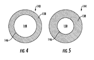
- FIG. 4 provides a cross-sectional front view of the upstream portion 140 of the fluid conduit 138 and FIG. 5 provides a cross-sectional front view of the intermediate portion 144 of the fluid conduit 138 according to one embodiment of the present invention.
- a portion of the flow passage 146 defined within the upstream portion 140 has a first cross-sectional flow area 148.
- a portion of the flow passage 146 defined within the intermediate portion 144 of the fluid conduit 138 has a second cross-sectional flow area 150.
- the second cross-sectional flow area 150 is less than the first cross-sectional flow area 148 so as to restrict flow of the liquid coolant 116 between the cooling system 100 component, such as the cooling circuit 108 and/or the heat exchanger 104 and the expansion tank 112 while allowing for the entrapped air to pass to the expansion tank 112.
- the second cross-sectional flow area 150 may be at least 10 percent to at least 80 percent less than the first cross-sectional area 148.
- the flow of liquid coolant from the cooling system 100 component such as the cooling circuit 108 and/or the heat exchanger 104 to the expansion tank 112 may be restricted or reduced by varying a cross-sectional shape of the flow passage 146 defined within the fluid conduit 138.
- the portion of the flow passage 146 defined in the upstream portion 140 of the fluid conduit 138 may have a substantially circular cross-sectional shape, as shown in FIG. 4
- the portion of the flow passage 146 defined within the intermediate portion 144 may have a substantially non-circular cross-sectional shape.
- the portion of the flow passage 146 in the intermediate portion 144 may have a substantially circular cross-sectional shape but may be smaller in diameter than the portion of the flow passage 146 extending through the upstream portion 140.
- the flow passage 146 in the intermediate portion 144 may have any non-circular cross-sectional shape which reduces or restricts flow between a corresponding component of the cooling system 100 and the expansion tank.
- FIGS. 6, 7 8, 9 and 10 provide various exemplary cross-sectional shapes of the flow passage 146 within the intermediate section 144 of the fluid conduit 138 according to various embodiments of the present invention.
- the cross-sectional shape of the flow passage 146 within the intermediate section 144 may be substantially crescent shaped.
- the cross-sectional shape of the flow passage 146 within the intermediate section 144 may be substantially oval or elliptical shaped.
- the cross-sectional shape of the flow passage 146 within the intermediate section 144 may be substantially star shaped.
- FIG. 6 the cross-sectional shape of the flow passage 146 within the intermediate section 144 may be substantially crescent shaped.
- the cross-sectional shape of the flow passage 146 within the intermediate section 144 may be substantially oval or elliptical shaped.
- the cross-sectional shape of the flow passage 146 within the intermediate section 144 may be substantially star shaped.
- the cross-sectional shape of the flow passage 146 within the intermediate section 144 may be substantially polygonal.
- the cross-sectional shape of the flow passage 146 within the intermediate section 144 may include multiple lobes in a daisy petal or cross pattern.
- the first cross-sectional flow area 148 of the flow passage 146 in the upstream portion 140 and the second cross-sectional flow area 150 of the flow passage 146 within the intermediate portion 144 may be different or varying.
- the second cross-sectional flow area 150 of the portion of the flow passage 146 defined within the intermediate portion 144 may be less than the first cross-sectional flow area 148 of the flow passage defined within the upstream portion 140.
- the cooling system 100 may include one or more of the deaeration lines 128 which include a fluid conduit 138 as described and shown herein for restricting or reducing liquid coolant flow to the expansion tank 112.
- a first deaeration line 152 having a fluid conduit 138 as described herein fluidly couples the cooling circuit 108 to the expansion tank 112.
- a second deaeration line 154 having a fluid conduit 138 as described herein fluidly couples the heat exchanger 104 to the expansion tank 112.
- a flow restrictor 156 may be disposed within the portion of the flow passage 146 of the fluid conduit 138 so as to restrict the flow of the liquid coolant 116 from a corresponding component of the liquid coolant system 100 such as the cooling circuit 108 and/or the heat exchanger 104 to the expansion tank 112.
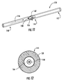
- FIG. 11 provides a perspective view of an exemplary flow restrictor disposed within the fluid conduit 138 of a deaeration line 128 according to one or more embodiments of the present invention. As shown in FIG. 11 , the flow restrictor 156 is fully inscribed within the fluid conduit 138.
- FIG. 12 provides a front cross-sectional view of the fluid conduit 138 and the flow restrictor 156 according to one or more embodiments.
- the flow restrictor includes a flow orifice 158 having a cross-sectional flow area 160 which is smaller than the cross sectional area 148 of the portion of the flow passage 146 defined within the upstream portion of the fluid conduit 138 ( FIG. 4 ), thus restricting or reducing flow of the liquid coolant through the deaeration line 128 to the expansion tank 112.
- the flow restrictor orifice may have any cross sectional shape such as any of those shown in FIGS. 5-10 .
- the flow restrictor may be held in position by a clamp 162 or other mechanical fastener suitable to hold the flow restrictor in place during operation of the cooling system 100. In alternate embodiments, the flow restrictor may be molded in place.
Landscapes
- Engineering & Computer Science (AREA)
- Mechanical Engineering (AREA)
- Chemical & Material Sciences (AREA)
- Combustion & Propulsion (AREA)
- General Engineering & Computer Science (AREA)
- Physics & Mathematics (AREA)
- Thermal Sciences (AREA)
- Air-Conditioning For Vehicles (AREA)
- Cooling Or The Like Of Electrical Apparatus (AREA)
Abstract
Description
- The present subject matter relates generally to work vehicles and, more particularly, to a cooling system for a work vehicle.
- A work vehicle generally includes an engine and a pressurized liquid cooling system for cooling the engine during operation. Typically, the cooling system includes various components including a heat exchanger such as an air cooled radiator, a centrifugal pump such as a water pump, a cooling circuit defined within the engine, a thermostat and an expansion or surge tank which is fluidly coupled to one or more of the components of the cooling system such as the cooling circuit and/or the heat exchanger.
- During operation, a liquid coolant flows from the heat exchanger at a first temperature, through the water pump and into the cooling circuit. The liquid coolant is routed through the cooling circuit to provide cooling to various internal components within the engine before flowing through the thermostat and back into an inlet of the heat exchanger at a second higher temperature. As the liquid coolant flows through the water pump, various fluid conduits and the cooling circuit, cavitation and/or other factors may result in air bubbles becoming entrapped within the liquid coolant. In addition, air which normally resides at a top portion of the heat exchanger when the cooling system is inactive also may contribute to air bubbles in the liquid coolant. The air bubbles may negatively impact the overall performance of the engine and/or the cooling system.
- Conventionally, the air bubbles are removed from the liquid coolant by routing a portion of the liquid coolant including the entrapped air bubbles to the expansion tank via one or more vent or deaeration lines. The liquid coolant collects in the expansion tank and the air bubbles separate from the liquid coolant. The liberated air is then vented to the atmosphere. The collected liquid coolant is then routed back to the cooing circuit via the water pump.
- Typically, the deaeration lines are fluidly open to the expansion tank. As a result, excess liquid coolant may flow into the expansion tank during operation of the engine, thus reducing the amount or volume of liquid coolant flowing directly back into the heat exchanger. In addition, the expansion tank is not as efficient as the heat exchanger at cooling the liquid coolant, thereby reducing the overall effectiveness of the cooling system.
- Accordingly, an improved cooling system for a work vehicle engine which restricts or reduces liquid coolant flow into the expansion tank during operation of the engine would be welcomed in the technology.
- Aspects and advantages of the invention will be set forth in part in the following description, or may be obvious from the description, or may be learned through practice of the invention.
- In one aspect, the present subject matter is directed to a liquid cooling system for a work vehicle. The cooling system may generally include an expansion tank and a deaeration line having a fluid conduit which fluidly couples the expansion tank to a component of the cooling system. The fluid conduit defines a flow passage therein and includes an upstream portion, a downstream portion and an intermediate portion where the intermediate portion is defined between the upstream and downstream portions. The flow passage within the intermediate portion has cross-sectional shape which restricts liquid coolant flow between the component and the expansion tank during operation of the work vehicle.
- In another aspect, the present subject matter is directed to a liquid cooling system for a work vehicle. The cooling system may generally include a cooling system component, the cooling system component including one of a cooling circuit defined within the engine and a heat exchanger, the cooling circuit having an inlet, an outlet and an auxiliary outlet coupled to the inlet, the heat exchanger being fluidly coupled to the outlet of the cooling circuit. The cooling system may further include an expansion tank and a deaeration line. The deaeration line includes a first fluid conduit fluidly coupling the expansion tank to one of the cooling system components. The first fluid conduit defines a flow passage therein and includes an upstream portion which is in fluid communication with the cooling system component, a downstream portion which is in fluid communication with the expansion tank and an intermediate portion which is defined between the upstream and downstream portions. The flow passage in the upstream portion has a first cross-sectional flow area and the flow passage within the intermediate portion has a second cross-sectional flow area. The second cross-sectional flow area is less than the first cross-sectional flow area to restrict liquid coolant flow between the cooling system component and the expansion tank during operation of the work vehicle.
- In a further aspect, the present subject matter is directed to a cooling system for a work vehicle. The cooling system may generally include an expansion tank and a fluid conduit which fluidly couples the expansion tank to a component of the cooling system where the fluid conduit defines a flow passage therein. The system further includes a flow restrictor disposed within the flow passage and fully inscribed within the fluid conduit. The flow restrictor restricts liquid coolant flow between the heat exchanger and the expansion tank.
- These and other features, aspects and advantages of the present invention will become better understood with reference to the following description and appended claims. The accompanying drawings, which are incorporated in and constitute a part of this specification, illustrate embodiments of the invention and, together with the description, serve to explain the principles of the invention.
- A full and enabling disclosure of the present invention, including the best mode thereof, directed to one of ordinary skill in the art, is set forth in the specification, which makes reference to the appended figures, in which:
-
FIG. 1 illustrates a side view of one embodiment of a work vehicle as may incorporate various embodiments of the present invention; -
FIG. 2 illustrates a schematic view of an exemplary cooling system of the work vehicle as may be incorporated with one or more embodiments of the present invention; -
FIG. 3 illustrates a cross-sectional side view of a portion of an exemplary fluid conduit of an exemplary deaeration line according to one embodiment of the present invention; -
FIG. 4 illustrates a cross-sectional front view of an upstream portion of an exemplary fluid conduit according to one embodiment of the present invention; -
FIG. 5 illustrates a cross-sectional front view of an intermediate portion of the exemplary fluid conduit as shown inFIG. 4 , according to one embodiment of the present invention; -
FIG. 6 illustrates a cross-sectional front view of an intermediate portion of the exemplary fluid conduit as shown inFIG. 4 , according to one embodiment of the present invention; -
FIG. 7 illustrates a cross-sectional front view of an intermediate portion of the exemplary fluid conduit as shown inFIG. 4 , according to one embodiment of the present invention; -
FIG. 8 illustrates a cross-sectional front view of an intermediate portion of the exemplary fluid conduit as shown inFIG. 4 , according to one embodiment of the present invention; -
FIG. 9 illustrates a cross-sectional front view of an intermediate portion of the exemplary fluid conduit as shown inFIG. 4 , according to one embodiment of the present invention; -
FIG. 10 illustrates a cross-sectional front view of an intermediate portion of the exemplary fluid conduit as shown inFIG. 4 , according to one embodiment of the present invention; -
FIG. 11 illustrates a perspective side of an exemplary fluid conduit of an exemplary deaeration line including a flow restrictor fully inscribed within the fluid conduit, according to one embodiment of the present invention; and -
FIG. 12 illustrates a cross-sectional front view of a portion of the exemplary fluid conduit as shown inFIG. 11 , according to one embodiment of the present invention. - Reference now will be made in detail to embodiments of the invention, one or more examples of which are illustrated in the drawings. Each example is provided by way of explanation of the invention, not limitation of the invention. In fact, it will be apparent to those skilled in the art that various modifications and variations can be made in the present invention without departing from the scope or spirit of the invention. For instance, features illustrated or described as part of one embodiment can be used with another embodiment to yield a still further embodiment. Thus, it is intended that the present invention covers such modifications and variations as come within the scope of the appended claims and their equivalents.
- In general, the present subject matter is directed to a liquid cooling system for a work vehicle. Specifically, in several embodiments, the cooling system corresponds to a fluid conduit which fluidly couples a component of the cooling system such as a heat exchanger (i.e. radiator) or a cooling circuit defined within the engine to an expansion tank. The fluid conduit is configured to restrict liquid coolant flow between the component and the expansion tank during operation of the engine. By reducing the liquid coolant flow to the expansion tank, additional liquid coolant may remain within the cooling circuit, thus improving overall cooling efficiency of the cooling system. In addition or in the alternative, reduction of the liquid coolant flow to the expansion tank may provide additional time for the entrapped air/gas to separate from the liquid coolant already collected in the expansion tank.
- For example, as will be described in greater detail below, an intermediate portion the fluid conduit may have cross-sectional shape which is different from a cross-section shape of an upstream portion of the fluid conduit, thus reducing or restricting liquid coolant flow through the fluid conduit to the expansion tank. In addition or in the alternative, the intermediate portion of the fluid conduit may have a cross-sectional flow area which is smaller or more constricted than the cross-section flow area of the upstream portion, thus reducing or restricting liquid coolant flow to the expansion tank. In addition or in the alternative, a flow restrictor may be disposed within the fluid conduit along the intermediate portion so as to reduce the cross-sectional flow area of the fluid conduit, thus reducing or restricting liquid coolant flow through the fluid conduit to the expansion tank.
- Referring now to the drawings,
FIG. 1 illustrates a side view of one embodiment of awork vehicle 10. As shown, thework vehicle 10 is configured as an agricultural tractor. However, in other embodiments, thework vehicle 10 may be configured as any other suitable work vehicle known in the art, such as various other agricultural vehicles, earth-moving vehicles, loaders and/or various other off-road vehicles. - As shown in
FIG. 1 , thework vehicle 10 includes a pair offront wheels 12, a pair orrear wheels 14 and achassis 16 coupled to and supported by thewheels cab 18 may be supported by a portion of thechassis 16 and may house various control orinput devices 20, 22 (e.g., levers, pedals, control panels, buttons and/or the like) for permitting an operator to control the operation of thework vehicle 10. For instance, as shown inFIG. 1 , thework vehicle 10 may include a Forward-Neutral-Reverse-Park (FNRP)lever 20 and anemergency brake lever 22 configured to be communicatively coupled to a suitable controller (not shown) for electronically controlling the operation of thevehicle 10. In addition, thework vehicle 10 may include anengine 24 and atransmission 26 mounted on thechassis 16. Thetransmission 26 may be operably coupled to theengine 24 and may provide variably adjusted gear ratios for transferring engine power to thewheels 14 via an axle/differential 28. Theengine 24,transmission 26, and axle/differential 28 may collectively define adrivetrain 30 of thework vehicle 10. - It should be appreciated that the configuration of the
work vehicle 10 described above and shown inFIG. 1 is provided only to place the present subject matter in an exemplary field of use. Thus, it should be appreciated that the present subject matter may be readily adaptable to any manner ofwork vehicle configuration 10. For example, in an alternative embodiment, a separate frame or chassis may be provided to which theengine 24,transmission 26, and differential 28 are coupled, a configuration common in smaller tractors. Still other configurations may use an articulated chassis to steer thework vehicle 10, or rely on tracks in lieu of thewheels work vehicle 10 may also be configured to be operably coupled to any suitable type of work implement, such as a trailer, spray boom, manure tank, feed grinder, plow and/or the like. In particular embodiments, the work vehicle includes a pressurizedliquid cooling system 100 fluidly coupled to theengine 24. -
FIG. 2 provides a flow diagram of one embodiment of thecooling system 100 fluidly coupled to theengine 24 for use with thework vehicle 10 shown inFIG. 1 . In general, thecooling system 100 will be described herein with reference to cooling theengine 24 of thework vehicle 10. However, the disclosedcooling system 100 may generally be utilized to cool an engine of any given work vehicle. - As shown in
FIG. 2 , thecooling system 100 generally includes various components fluidly coupled via multiplefluid conduits 102 such as hoses or pipes so as to form a closed loop cooling system. Conventionally, the components of thecooling system 100 include aheat exchanger 104 such as an air cooled radiator, a centrifugal orwater pump 106, a cooling circuit orchannel 108 defined within theengine 24 and shown in dotted lines, athermostat 110 and an expansion orsurge tank 112. In particular configurations, thecooling system 100 also may include a secondary heat exchanger orheater 114 for providing heat to the operator cab 18 (FIG. 1 ). - In operation, the
water pump 106 causes aliquid coolant 116 to flow from anoutlet 118 of theheat exchanger 104 into aninlet 120 of thecooling circuit 108. Theliquid coolant 116 circulates through various channels of thecooling circuit 108 within theengine 24, including but not limited to an oil cooler (not shown) and/or acylinder head portion 122 of theengine 24. Theliquid coolant 116 then flows out of thecooling circuit 108 viaoutlet 124, through thethermostat 110 and into aninlet 126 of theheat exchanger 104. Theheat exchanger 104 removes thermal energy from theliquid coolant 116 as it is routed back to theoutlet 118 before being recirculated through thecooling circuit 108 via thewater pump 106. In particular configurations, a portion of theliquid coolant 116 may flow from thethermostat 110 directly to thepump 106. In certain embodiments, wherein thecooling system 100 includes thesecondary heat exchanger 114, a portion of theliquid coolant 116 may be routed from thecooling circuit 108, to thesecondary heat exchanger 114 and back to thepump 106. - As the
liquid coolant 116 flows through the various components of thecooling system 100, such as thecooling circuit 108 and/or theheat exchanger 104, cavitation within the cooling system and/or other factors may result in air becoming entrapped within theliquid coolant 116, particularly in thecylinder head portion 122 of theengine 24, thereby potentially having a negative effect on the overall performance of theengine 24 and/orcooling system 100. In order to allow the entrapped air to escape from theliquid coolant 116, various components of thecooling system 100 may be fluidly coupled to theexpansion tank 112 via vent ordeaeration lines 128. - As shown in
FIG. 2 , adeaeration line 128 may extend between anauxiliary outlet 130 of thecooling circuit 108 and aninlet 132 of theexpansion tank 112 so as to fluidly couple thecooling circuit 108 to theexpansion tank 112. In addition or in the alternative, adeaeration line 128 may extend between anoverflow outlet 134 of theheat exchanger 104 and aninlet 136 of theexpansion tank 112 so as to fluidly couple theheat exchanger 104 to theexpansion tank 112. The deaeration line(s) 128 may comprise one or more fluid conduits such as pipes or hoses fluidly connected in series and which define a flow path between the corresponding component and the expansion tank. - Because the deaeration line(s) 128 are always fluidly open to the
expansion tank 112, there is the possibility that too much of theliquid coolant 116 will freely flow into theexpansion tank 112, thus unnecessarily depleting the volume ofliquid coolant 116 flowing directly back to theheat exchanger 104 from thecooling circuit 108. In addition, theexpansion tank 112 is not generally effective at cooling theliquid coolant 116 collected in theexpansion tank 112. Therefore, it is beneficial to restrict or reduce the flow ofliquid coolant 116 to theexpansion tank 112 in order to improve the overall performance of thecooling system 100 by allowing a minimum amount ofliquid coolant 116 to flow to theexpansion tank 112, while still providing a flow path to thedeaeration tank 112 for the entrapped air. -
FIG. 3 provides an enlarged cross-sectional side view of an exemplaryfluid conduit 138 of anexemplary deaeration line 128 according to various embodiments of the present invention. As shown inFIG. 3 , thefluid conduit 138 includes an inlet orupstream portion 140, an outlet ordownstream portion 142 and anintermediate portion 144 which is defined between the upstream anddownstream portions fluid conduit 138 is continuous or unbroken between theupstream portion 140 and thedownstream portion 142 and defines a continuous orunbroken flow passage 146 therein. Theupstream portion 140 may be configured to connect directly to an outlet of a component of thecooling system 100 or to an adjacent fluid conduit of thedeaeration line 128. Thedownstream portion 142 may be configured to connect directly to the expansion tank 112 (FIG. 2 ) or to an adjacent fluid conduit of thedeaeration line 128. In particular embodiments, theintermediate portion 144 corresponds to a portion of thefluid conduit 138 where a cross-sectional area and/or cross-sectional shape of a portion of theflow passage 146 varies or is different from a cross sectional area and/or cross-sectional shape of a portion of theflow passage 146 which is upstream therefrom. -
FIG. 4 provides a cross-sectional front view of theupstream portion 140 of thefluid conduit 138 andFIG. 5 provides a cross-sectional front view of theintermediate portion 144 of thefluid conduit 138 according to one embodiment of the present invention. As shown inFIG. 4 a portion of theflow passage 146 defined within theupstream portion 140 has a firstcross-sectional flow area 148. As shown inFIG. 5 , a portion of theflow passage 146 defined within theintermediate portion 144 of thefluid conduit 138 has a secondcross-sectional flow area 150. In one embodiment, as shown inFIGS. 4 and 5 , the secondcross-sectional flow area 150 is less than the firstcross-sectional flow area 148 so as to restrict flow of theliquid coolant 116 between thecooling system 100 component, such as thecooling circuit 108 and/or theheat exchanger 104 and theexpansion tank 112 while allowing for the entrapped air to pass to theexpansion tank 112. For example, in particular embodiments, the secondcross-sectional flow area 150 may be at least 10 percent to at least 80 percent less than the firstcross-sectional area 148. - In various embodiments, the flow of liquid coolant from the
cooling system 100 component such as thecooling circuit 108 and/or theheat exchanger 104 to theexpansion tank 112 may be restricted or reduced by varying a cross-sectional shape of theflow passage 146 defined within thefluid conduit 138. For example, the portion of theflow passage 146 defined in theupstream portion 140 of thefluid conduit 138 may have a substantially circular cross-sectional shape, as shown inFIG. 4 , and the portion of theflow passage 146 defined within theintermediate portion 144 may have a substantially non-circular cross-sectional shape. In other embodiments, the portion of theflow passage 146 in theintermediate portion 144 may have a substantially circular cross-sectional shape but may be smaller in diameter than the portion of theflow passage 146 extending through theupstream portion 140. Theflow passage 146 in theintermediate portion 144 may have any non-circular cross-sectional shape which reduces or restricts flow between a corresponding component of thecooling system 100 and the expansion tank. -
FIGS. 6, 7 8, 9 and 10 provide various exemplary cross-sectional shapes of theflow passage 146 within theintermediate section 144 of thefluid conduit 138 according to various embodiments of the present invention. In one embodiment, as shown inFIG. 6 , the cross-sectional shape of theflow passage 146 within theintermediate section 144 may be substantially crescent shaped. In one embodiment, as shown inFIG. 7 , the cross-sectional shape of theflow passage 146 within theintermediate section 144 may be substantially oval or elliptical shaped. In one embodiment, as shown inFIG. 8 , the cross-sectional shape of theflow passage 146 within theintermediate section 144 may be substantially star shaped. In one embodiment, as shown inFIG. 9 , the cross-sectional shape of theflow passage 146 within theintermediate section 144 may be substantially polygonal. In one embodiment, as shown inFIG. 10 , the cross-sectional shape of theflow passage 146 within theintermediate section 144 may include multiple lobes in a daisy petal or cross pattern. - In addition to having varying cross-sectional shapes, in particular embodiments, the first
cross-sectional flow area 148 of theflow passage 146 in theupstream portion 140 and the secondcross-sectional flow area 150 of theflow passage 146 within theintermediate portion 144 may be different or varying. For example, the secondcross-sectional flow area 150 of the portion of theflow passage 146 defined within theintermediate portion 144 may be less than the firstcross-sectional flow area 148 of the flow passage defined within theupstream portion 140. - As previously provided, the
cooling system 100 may include one or more of thedeaeration lines 128 which include afluid conduit 138 as described and shown herein for restricting or reducing liquid coolant flow to theexpansion tank 112. For example, in one embodiment, afirst deaeration line 152 having afluid conduit 138 as described herein fluidly couples thecooling circuit 108 to theexpansion tank 112. In addition or in the alternative, asecond deaeration line 154 having afluid conduit 138 as described herein fluidly couples theheat exchanger 104 to theexpansion tank 112. - In one embodiment, a
flow restrictor 156 may be disposed within the portion of theflow passage 146 of thefluid conduit 138 so as to restrict the flow of theliquid coolant 116 from a corresponding component of theliquid coolant system 100 such as thecooling circuit 108 and/or theheat exchanger 104 to theexpansion tank 112.FIG. 11 provides a perspective view of an exemplary flow restrictor disposed within thefluid conduit 138 of adeaeration line 128 according to one or more embodiments of the present invention. As shown inFIG. 11 , theflow restrictor 156 is fully inscribed within thefluid conduit 138.FIG. 12 provides a front cross-sectional view of thefluid conduit 138 and theflow restrictor 156 according to one or more embodiments. - As shown in
FIGS. 11 and 12 , the flow restrictor includes aflow orifice 158 having across-sectional flow area 160 which is smaller than the crosssectional area 148 of the portion of theflow passage 146 defined within the upstream portion of the fluid conduit 138 (FIG. 4 ), thus restricting or reducing flow of the liquid coolant through thedeaeration line 128 to theexpansion tank 112. The flow restrictor orifice may have any cross sectional shape such as any of those shown inFIGS. 5-10 . As shown, the flow restrictor may be held in position by aclamp 162 or other mechanical fastener suitable to hold the flow restrictor in place during operation of thecooling system 100. In alternate embodiments, the flow restrictor may be molded in place. - This written description uses examples to disclose the invention, including the best mode, and also to enable any person skilled in the art to practice the invention, including making and using any devices or cooling systems and performing any incorporated methods. The patentable scope of the invention is defined by the claims, and may include other examples that occur to those skilled in the art. Such other examples are intended to be within the scope of the claims if they include structural elements that do not differ from the literal language of the claims, or if they include equivalent structural elements with insubstantial differences from the literal languages of the claims.
Claims (8)
- A liquid cooling system (100) for an engine (24) of a work vehicle (10), the cooling system (100) comprising:an expansion tank (112) and a deaeration line (128) having a fluid conduit (138) fluidly coupling the expansion tank (112) to a component of the cooling system, the fluid conduit (138) defining a flow passage (146) therein, the fluid conduit (138) having an upstream portion (140), a downstream portion (142) and an intermediate portion (144) defined between the upstream (140) and downstream (142) portions;wherein the flow passage (146) within the intermediate portion (144) has cross-sectional shape which restricts liquid coolant flow between the component and the expansion tank (112).
- The cooling system (100) of claim 1, wherein the flow passage in the upstream portion (140) has a first cross-sectional flow area (148) and the flow passage in the intermediate portion (144) has a second cross-sectional flow area (150), wherein the second cross-sectional flow area (150) is less than the first cross-sectional flow area (148).
- The cooling system (100) of claim 1, wherein the cross-sectional shape of the flow passage in the intermediate portion (144) is circular.
- The cooling system of (100) claim 1, wherein the cross-sectional shape of the flow passage in the intermediate portion (144) is non-circular.
- The cooling system (100) of claim 1, wherein the cross-sectional shape of the flow passage in the intermediate portion (144) is crescent, elliptical or cross shaped.
- The cooling system (100) as in claim 1, wherein the cross-sectional shape of the flow passage in the intermediate portion (144) is polygonal.
- The cooling system (100) as in claim 1, wherein the component of the cooling system is a cooling circuit defined within the engine (24) of the work vehicle (10).
- The cooling system (100) of claim 1, wherein the component of the cooling system is a heat exchanger (104).
Applications Claiming Priority (1)
| Application Number | Priority Date | Filing Date | Title |
|---|---|---|---|
| US14/468,402 US20160059672A1 (en) | 2014-08-26 | 2014-08-26 | Cooling system for a work vehicle |
Publications (1)
| Publication Number | Publication Date |
|---|---|
| EP2990624A1 true EP2990624A1 (en) | 2016-03-02 |
Family
ID=53969282
Family Applications (1)
| Application Number | Title | Priority Date | Filing Date |
|---|---|---|---|
| EP15182188.1A Withdrawn EP2990624A1 (en) | 2014-08-26 | 2015-08-24 | Cooling system for a work vehicle |
Country Status (4)
| Country | Link |
|---|---|
| US (1) | US20160059672A1 (en) |
| EP (1) | EP2990624A1 (en) |
| CN (1) | CN105386849A (en) |
| BR (1) | BR102015020300A2 (en) |
Families Citing this family (6)
| Publication number | Priority date | Publication date | Assignee | Title |
|---|---|---|---|---|
| BR102015026378A2 (en) * | 2014-10-21 | 2017-07-11 | Modine Manufacturing Company | COOLING MODULE WITH A TANK OF INTEGRATED COMPENSATION TO HIM |
| DE102017116600A1 (en) * | 2017-07-24 | 2019-01-24 | Volkswagen Aktiengesellschaft | Cooling system and motor vehicle |
| US11753984B2 (en) * | 2020-10-14 | 2023-09-12 | Deere & Company | Coolant pump module |
| CN112627964A (en) * | 2020-12-01 | 2021-04-09 | 潍柴动力股份有限公司 | Integrated form gas removal pipeline structure and engine |
| CN113218447B (en) * | 2021-04-29 | 2023-01-10 | 中汽研汽车检验中心(天津)有限公司 | Oil level self-balancing test equipment for oil-cooled motor test |
| DK181629B1 (en) * | 2022-11-14 | 2024-08-13 | Man Energy Solutions Filial Af Man Energy Solutions Se Tyskland | Large two-stroke uniflow scavenged internal combustion engine configured to operate with high jacket water temperature |
Citations (5)
| Publication number | Priority date | Publication date | Assignee | Title |
|---|---|---|---|---|
| FR2388133A1 (en) * | 1977-04-19 | 1978-11-17 | Renault | IMPROVEMENT OF THE COOLING CIRCUITS OF INTERNAL COMBUSTION ENGINES |
| EP1505273A2 (en) * | 2003-08-06 | 2005-02-09 | Ford Global Technologies, LLC | Cooling system expansion tank |
| FR2866064A1 (en) * | 2004-02-11 | 2005-08-12 | Trelleborg Fluid Systems Geie | Cooling circuit liquid phase control device for motor vehicle, has orifices provided on part of fluid delivery pipe projecting into enclosure, and respectively opening into enclosure at levels situated above and below maximum fluid level |
| US20070215073A1 (en) * | 2006-03-16 | 2007-09-20 | Freightliner Llc | Surge tank |
| WO2009113019A2 (en) * | 2008-03-10 | 2009-09-17 | Land Rover | A cooling system expansion tank |
Family Cites Families (40)
| Publication number | Priority date | Publication date | Assignee | Title |
|---|---|---|---|---|
| US1305668A (en) * | 1919-06-03 | Walter n | ||
| US752175A (en) * | 1904-02-16 | Mute for water-pipes | ||
| US910192A (en) * | 1906-04-27 | 1909-01-19 | Philippe Jules Grouvelle | Tube. |
| US1329419A (en) * | 1918-12-23 | 1920-02-03 | Loomis Allen | Cooling system for engines |
| US1698314A (en) * | 1923-11-09 | 1929-01-08 | Bailey Meter Co | Flow meter |
| US2408374A (en) * | 1943-11-11 | 1946-10-01 | Linde Air Prod Co | Cooling system for internal-combustion engines |
| US2494427A (en) * | 1945-02-07 | 1950-01-10 | Gen Motors Corp | Deaerator |
| US2724246A (en) * | 1954-04-01 | 1955-11-22 | Charles E Lowe | Method and means for improving the utilization of volatile refrigerants in heat exchangers |
| US3028716A (en) * | 1957-02-12 | 1962-04-10 | Ford Motor Co | Fluid separator |
| US3759233A (en) * | 1969-05-23 | 1973-09-18 | Caterpillar Tractor Co | Engine cooling system |
| US3625257A (en) * | 1970-07-15 | 1971-12-07 | Modine Mfg Co | Fluid flow tube |
| US3636983A (en) * | 1970-08-14 | 1972-01-25 | Edwin J Keyser | Method and apparatus for increasing fluid flow |
| US3702144A (en) * | 1970-10-06 | 1972-11-07 | Atlas Pacific Eng Co | Orifice structure having two different flow rates |
| US3774645A (en) * | 1971-12-06 | 1973-11-27 | Universal Oil Prod Co | Flange-free venturi nozzle insert |
| US3945366A (en) * | 1973-12-20 | 1976-03-23 | Matthews Roe I | Oxygen supply system for IC engines |
| US3894562A (en) * | 1973-12-20 | 1975-07-15 | Jr Charles D Moseley | Fluid flow controller |
| FR2408722A1 (en) * | 1977-11-10 | 1979-06-08 | Berliet Automobiles | ADVANCED COOLING CIRCUIT FOR AN INTERNAL COMBUSTION ENGINE |
| HU176054B (en) * | 1978-11-30 | 1980-12-28 | Autoipari Kutato Intezet | Automatic deaeration plant for forced-flowing fluid system particularly for cooling system of internal combustion engine |
| US4346757A (en) * | 1980-09-10 | 1982-08-31 | Borg-Warner Corporation | Automotive cooling system using a non-pressurized reservoir bottle |
| US4466741A (en) * | 1982-01-16 | 1984-08-21 | Hisao Kojima | Mixing element and motionless mixer |
| JPS62144738A (en) * | 1985-12-20 | 1987-06-27 | Hisao Kojima | Liquid mixer |
| JP2686078B2 (en) * | 1987-07-16 | 1997-12-08 | 久夫 小嶋 | Mixing element |
| US5156680A (en) * | 1991-07-30 | 1992-10-20 | Rockwell International Corporation | Flow restrictor for a fluid |
| US5255636A (en) * | 1992-07-01 | 1993-10-26 | Evans John W | Aqueous reverse-flow engine cooling system |
| DE19538239C1 (en) * | 1995-10-13 | 1997-04-24 | Daimler Benz Ag | Coolant flow in a cooling circuit of a liquid-cooled internal combustion engine |
| US5992465A (en) * | 1996-08-02 | 1999-11-30 | Jansen; Robert C. | Flow system for pipes, pipe fittings, ducts and ducting elements |
| DE19814650C2 (en) * | 1998-04-01 | 2002-02-28 | Aeroquip Vickers Internat Gmbh | Process for producing a throttle point in a hose and a throttle point in a hose |
| US6276397B1 (en) * | 2000-06-12 | 2001-08-21 | Flow Design, Inc. | Apparatus and method for shaping fluid flow |
| DE10139314A1 (en) * | 2001-08-09 | 2003-03-06 | Deere & Co | Cooling system for motor vehicle drives |
| GB0220521D0 (en) * | 2002-09-04 | 2002-10-09 | Ford Global Tech Inc | A motor vehicle and a thermostatically controlled valve therefor |
| US7114525B2 (en) * | 2003-08-29 | 2006-10-03 | Dana Corporation | Method and apparatus for reduction of fluid-borne noise in hydraulic systems |
| NL1025624C2 (en) * | 2004-03-03 | 2005-09-07 | Solvist | Flow restriction device for use in drug metering device, has opening having specific diameter, formed in plastic baffle which is formed integrally with conduit |
| SE529541C2 (en) * | 2005-12-05 | 2007-09-11 | Volvo Lastvagnar Ab | Cooling |
| EP2047078A4 (en) * | 2006-07-20 | 2013-11-27 | Volvo Lastvagnar Ab | Cooling system |
| DE102008057291B4 (en) * | 2008-11-14 | 2012-10-04 | Albert-Ludwigs-Universität Freiburg | Apparatus and method for producing a drop of a liquid |
| SE533055C2 (en) * | 2008-11-21 | 2010-06-15 | Scania Cv Ab | expansion Tank |
| US8936392B2 (en) * | 2010-06-15 | 2015-01-20 | Ecosphere Technologies, Inc. | Hydrodynamic cavitation device |
| US20130126184A1 (en) * | 2011-11-17 | 2013-05-23 | David P. Gerrard | Reactive choke for automatic wellbore fluid management and methods of using same |
| AU2011265408A1 (en) * | 2011-12-21 | 2013-07-11 | Sandvik Intellectual Property Ab | Flow Restrictor and Drilling Assembly |
| TWM458497U (en) * | 2013-04-08 | 2013-08-01 | guo-zhen Cai | Water hammer cancellation device |
-
2014
- 2014-08-26 US US14/468,402 patent/US20160059672A1/en not_active Abandoned
-
2015
- 2015-08-24 EP EP15182188.1A patent/EP2990624A1/en not_active Withdrawn
- 2015-08-24 BR BR102015020300A patent/BR102015020300A2/en not_active Application Discontinuation
- 2015-08-25 CN CN201510526381.1A patent/CN105386849A/en active Pending
Patent Citations (5)
| Publication number | Priority date | Publication date | Assignee | Title |
|---|---|---|---|---|
| FR2388133A1 (en) * | 1977-04-19 | 1978-11-17 | Renault | IMPROVEMENT OF THE COOLING CIRCUITS OF INTERNAL COMBUSTION ENGINES |
| EP1505273A2 (en) * | 2003-08-06 | 2005-02-09 | Ford Global Technologies, LLC | Cooling system expansion tank |
| FR2866064A1 (en) * | 2004-02-11 | 2005-08-12 | Trelleborg Fluid Systems Geie | Cooling circuit liquid phase control device for motor vehicle, has orifices provided on part of fluid delivery pipe projecting into enclosure, and respectively opening into enclosure at levels situated above and below maximum fluid level |
| US20070215073A1 (en) * | 2006-03-16 | 2007-09-20 | Freightliner Llc | Surge tank |
| WO2009113019A2 (en) * | 2008-03-10 | 2009-09-17 | Land Rover | A cooling system expansion tank |
Also Published As
| Publication number | Publication date |
|---|---|
| US20160059672A1 (en) | 2016-03-03 |
| BR102015020300A2 (en) | 2016-07-05 |
| CN105386849A (en) | 2016-03-09 |
Similar Documents
| Publication | Publication Date | Title |
|---|---|---|
| US20160059672A1 (en) | Cooling system for a work vehicle | |
| US20090013942A1 (en) | Cooling Structure for a Work Vehicle | |
| EP3267007B1 (en) | Utility vehicle fluid cooling | |
| JP6566817B2 (en) | Work vehicle | |
| JP6448507B2 (en) | Work vehicle | |
| DE112014000492T5 (en) | Double-cooler machine cooling module with single coolant loop | |
| US20110277973A1 (en) | Cooling Circuit With Parallel Radiators | |
| CN109296444B (en) | Cooling system and motor vehicle | |
| US10571196B2 (en) | Vehicle cooling system with charge air cooling | |
| EP3159201B1 (en) | Integrated intake and deaeration assembly for a work vehicle | |
| US20200047694A1 (en) | Tractor | |
| JP2018069746A (en) | Work vehicle | |
| DE102018005067A1 (en) | Straddle-vehicle | |
| EP3210858B1 (en) | Tractor bonnet | |
| EP3101247B1 (en) | System and method for cooling charge air and excess fuel for a turbocharged diesel engine | |
| DE112015000071T5 (en) | Inlet device for engine | |
| WO2024017733A1 (en) | Motor vehicle with temperature control device | |
| CN203452898U (en) | Expansion tank assembly and operation machine with same | |
| CN206034530U (en) | All -hydraulic wheeled excavator cooling system | |
| JP2017030521A (en) | Radiator and work vehicle including the same | |
| CN206094978U (en) | Heat radiator for automobile | |
| DE102016103095A1 (en) | Motor assembly with a coolant channel | |
| JP2017030522A (en) | Tractor | |
| KR200490125Y1 (en) | Saddle type rice transplanter | |
| US12000325B2 (en) | Coolant system for an engine |
Legal Events
| Date | Code | Title | Description |
|---|---|---|---|
| PUAI | Public reference made under article 153(3) epc to a published international application that has entered the european phase |
Free format text: ORIGINAL CODE: 0009012 |
|
| AK | Designated contracting states |
Kind code of ref document: A1 Designated state(s): AL AT BE BG CH CY CZ DE DK EE ES FI FR GB GR HR HU IE IS IT LI LT LU LV MC MK MT NL NO PL PT RO RS SE SI SK SM TR |
|
| AX | Request for extension of the european patent |
Extension state: BA ME |
|
| 17P | Request for examination filed |
Effective date: 20160902 |
|
| RBV | Designated contracting states (corrected) |
Designated state(s): AL AT BE BG CH CY CZ DE DK EE ES FI FR GB GR HR HU IE IS IT LI LT LU LV MC MK MT NL NO PL PT RO RS SE SI SK SM TR |
|
| STAA | Information on the status of an ep patent application or granted ep patent |
Free format text: STATUS: THE APPLICATION IS DEEMED TO BE WITHDRAWN |
|
| 18D | Application deemed to be withdrawn |
Effective date: 20160903 |