EP2990596A2 - Low pressure shaft - Google Patents
Low pressure shaft Download PDFInfo
- Publication number
- EP2990596A2 EP2990596A2 EP15179057.3A EP15179057A EP2990596A2 EP 2990596 A2 EP2990596 A2 EP 2990596A2 EP 15179057 A EP15179057 A EP 15179057A EP 2990596 A2 EP2990596 A2 EP 2990596A2
- Authority
- EP
- European Patent Office
- Prior art keywords
- low pressure
- aft section
- engine
- section
- shaft
- Prior art date
- Legal status (The legal status is an assumption and is not a legal conclusion. Google has not performed a legal analysis and makes no representation as to the accuracy of the status listed.)
- Granted
Links
Images


Classifications
-
- F—MECHANICAL ENGINEERING; LIGHTING; HEATING; WEAPONS; BLASTING
- F02—COMBUSTION ENGINES; HOT-GAS OR COMBUSTION-PRODUCT ENGINE PLANTS
- F02C—GAS-TURBINE PLANTS; AIR INTAKES FOR JET-PROPULSION PLANTS; CONTROLLING FUEL SUPPLY IN AIR-BREATHING JET-PROPULSION PLANTS
- F02C3/00—Gas-turbine plants characterised by the use of combustion products as the working fluid
- F02C3/04—Gas-turbine plants characterised by the use of combustion products as the working fluid having a turbine driving a compressor
-
- F—MECHANICAL ENGINEERING; LIGHTING; HEATING; WEAPONS; BLASTING
- F01—MACHINES OR ENGINES IN GENERAL; ENGINE PLANTS IN GENERAL; STEAM ENGINES
- F01D—NON-POSITIVE DISPLACEMENT MACHINES OR ENGINES, e.g. STEAM TURBINES
- F01D5/00—Blades; Blade-carrying members; Heating, heat-insulating, cooling or antivibration means on the blades or the members
- F01D5/02—Blade-carrying members, e.g. rotors
- F01D5/025—Fixing blade carrying members on shafts
-
- F—MECHANICAL ENGINEERING; LIGHTING; HEATING; WEAPONS; BLASTING
- F01—MACHINES OR ENGINES IN GENERAL; ENGINE PLANTS IN GENERAL; STEAM ENGINES
- F01D—NON-POSITIVE DISPLACEMENT MACHINES OR ENGINES, e.g. STEAM TURBINES
- F01D5/00—Blades; Blade-carrying members; Heating, heat-insulating, cooling or antivibration means on the blades or the members
- F01D5/02—Blade-carrying members, e.g. rotors
- F01D5/026—Shaft to shaft connections
-
- F—MECHANICAL ENGINEERING; LIGHTING; HEATING; WEAPONS; BLASTING
- F01—MACHINES OR ENGINES IN GENERAL; ENGINE PLANTS IN GENERAL; STEAM ENGINES
- F01D—NON-POSITIVE DISPLACEMENT MACHINES OR ENGINES, e.g. STEAM TURBINES
- F01D5/00—Blades; Blade-carrying members; Heating, heat-insulating, cooling or antivibration means on the blades or the members
- F01D5/02—Blade-carrying members, e.g. rotors
- F01D5/06—Rotors for more than one axial stage, e.g. of drum or multiple disc type; Details thereof, e.g. shafts, shaft connections
- F01D5/066—Connecting means for joining rotor-discs or rotor-elements together, e.g. by a central bolt, by clamps
-
- F—MECHANICAL ENGINEERING; LIGHTING; HEATING; WEAPONS; BLASTING
- F05—INDEXING SCHEMES RELATING TO ENGINES OR PUMPS IN VARIOUS SUBCLASSES OF CLASSES F01-F04
- F05D—INDEXING SCHEME FOR ASPECTS RELATING TO NON-POSITIVE-DISPLACEMENT MACHINES OR ENGINES, GAS-TURBINES OR JET-PROPULSION PLANTS
- F05D2240/00—Components
- F05D2240/60—Shafts
Definitions
- the present invention relates to a low pressure shaft for interconnecting a fan or low pressure compressor of a gas turbine engine with a low pressure turbine of the engine
- Internal interconnecting shafts are major parts of gas turbine engines. Their prime purpose is to transmit driving power from the turbine to the compressor end of a rotor. Within a two or three shaft engine the innermost rotor is the low pressure (LP) rotor which transmits power from the LP turbine to the fan or LP compressor. Typically, the LP shaft carries the highest torque load of any of the shafts.
- LP low pressure
- Shaft joints may have to carry a combination of torque, axial load and bending moment.
- Three basic types of joint are in use, namely: bolted joints, splines and curvic couplings.
- Bolted joints are relatively low cost, but splined and curvic couplings have higher torque-carrying capabilities due to their use of interlocking teeth.
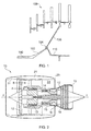
- Figure 1 shows schematically a longitudinal cross-section through the rear portion of a low pressure shaft of an engine.
- a cylindrical section 100 of the rear portion extends forwardly towards the compressor end of the rotor.
- the shaft has an aft section 102 or "cone" whose diameter expands progressively with distance along the rearward direction of the engine to terminate in one side of an annular curvic coupling 104.
- the other side of the coupling is the inner end of a drive arm 106 which extends, coaxially with the shaft, radially inwardly from the low pressure turbine 108 of the engine.
- a stubshaft 110 extending rearwardly from the joint provides a location for supporting bearings (not shown) for the shaft.
- An object of the present invention is to reduce the mass of low pressure shaft and/or to reduce peak stresses in the shaft.
- the present invention provides a low pressure shaft for interconnecting a fan or low pressure compressor of a gas turbine engine with a low pressure turbine of the engine, the shaft having an aft section whose diameter expands progressively with distance along the rearward direction of the engine, and an annular joint portion at the rear end of the aft section for joining the shaft to a drive arm of the low pressure turbine; wherein the rate of expansion of the diameter of the aft section decreases with distance along the rearward direction of the engine.
- the aft section can be considered as having a forward portion and a rearward portion, the forward portion having a greater rate of expansion of diameter than the rearward portion.
- the rate of expansion of the diameter of the aft section may continually decrease with distance along the rearward direction of the engine, or alternatively the aft section may have a discrete forward portion and a discrete rearward portion, the forward portion having a greater rate of expansion of diameter than the rearward portion.
- the present invention provides a gas turbine engine having the low pressure shaft of the first aspect interconnecting a fan or low pressure compressor of the engine with a low pressure turbine of the engine
- the shaft may be substantially cylindrical forward of the aft section.
- the aft section may have an elliptical section profile.
- Such a profile can very efficiently distribute stresses along the aft section.
- the curved walls of the elliptical section profile can be difficult to manufacture.
- another option is to form the aft section as an axial row of two or more frustoconical sub-sections, wherein, for each pair of adjacent frustoconical sub-sections, the cone angle of the rearward sub-section is less than the cone angle of the forward sub-section.
- the frustoconical sub-sections, having substantially straight-sided walls can be easier to manufacture than the elliptical section profile. Further, the more frustoconical sub-sections are used, the closer the aft section approximates to a section having the elliptical section profile.
- the annular joint portion may be configured to form a curvic coupling with the drive arm.
- the wall thickness of the aft section may decrease with distance along the rearward direction of the engine. For example, regions with decreasing wall thickness (typically at the front end of the aft section) may occupy at least 50% of the axial extent of the aft section. The remaining regions of the aft section (typically at the rear end of the aft section) may then be of substantially constant wall thickness.
- the shaft may further have an annular stiffening formation which bridges the rear end of the aft section and the joint portion, the wall thickness of the stiffening formation being greater than the wall thickness of the aft section at its rear end.
- the wall thickness of the stiffening formation may increase to be about double that of the wall thickness of the aft section at its rear end.
- Such a stiffening formation can reduce component movement at the joint with the drive arm, displacing such movement forward into plane stress regions of the aft section.
- Another option, however, is to form the stiffening formation such that it curves radially outwardly from the rear end of the aft section.
- the stiffening formation may have the same wall thickness as the wall thickness of the aft section at its rearmost end.
- the axial length of the stiffening formation may be less than 5%, for example less than 2%, of the axial length of the aft section.
- the drive arm can be a frustoconical section which extends, coaxially with the shaft, radially inwardly from the low pressure turbine.
- a ducted fan gas turbine is generally indicated at 10 and has a principal and rotational axis X-X.
- the engine comprises, in axial flow series, an air intake 11, a propulsive fan 12, an intermediate pressure (IP) compressor 13, a high pressure (HP) compressor 14, combustion equipment 15, an HP turbine 16, an IP turbine 17, an LP turbine 18 and a core engine exhaust nozzle 19.
- a nacelle 21 generally surrounds the engine 10 and defines the intake 11, a bypass duct 22 and a bypass exhaust nozzle 23.
- air entering the intake 11 is accelerated by the fan 12 to produce two air flows: a first air flow A into the intermediate-pressure compressor 13 and a second air flow B which passes through the bypass duct 22 to provide propulsive thrust.
- the IP compressor 13 compresses the air flow A directed into it before delivering that air to the HP compressor 14 where further compression takes place.
- the compressed air exhausted from the high-pressure compressor 14 is directed into the combustion equipment 15 where it is mixed with fuel and the mixture combusted.
- the resultant hot combustion products then expand through, and thereby drive the HP, IP and LP turbines 16, 17, 18 before being exhausted through the nozzle 19 to provide additional propulsive thrust.
- the HP, IP and LP turbines respectively drive the HPand IP compressors 14, 13 and the fan 12 by suitable interconnecting shafts.
- Figure 3 shows schematically (a) a longitudinal cross-section through the rear portion of the LP interconnecting shaft of the engine of Figure 2 , and (b) a close-up view of a selected area of the cross-section.
- the shaft has a cylindrical section 30 which extends forwardly towards the fan.
- An aft section 32 then extends rearwardly from the cylindrical section. The diameter of the aft section expands progressively with distance along the rearward direction of the engine.
- a short annular stiffening portion 34 bridges the rear end of the aft section and an annular joint portion 36 which forms a joint with a corresponding joint portion 38 at the end of a frustoconical drive arm 40 extending inwardly from the LP turbine.
- a stubshaft 42 extends rearwardly from the joint.
- the joint may be a curvic joint.
- the LP shaft differs in important respects from the shaft shown in Figure 1 .
- the aft section 32 is configured such that the rate of expansion of its diameter decreases with distance along the rearward direction of the engine. This is achieved by forming the aft section as two frustoconical sub-sections 32a, 32b, with the cone angle of the front subsection 32a being larger than that of the rear subsection 32b.
- the two sub-sections are produced in respective forging operations, with a bend 32c being formed at the boundary of the forging envelopes, and the front sub-section being longer than the rear sub-section.
- the aft section decreases gradually in wall thickness over the length of the front sub-section, and is approximately of constant wall thickness over the length of the rear sub-section.
- the stiffening portion 34 can reduce component movement in the region of the joint portion 36, where stress-raising shape complexities can lead to high peak stresses, and help to displace such movement into the plane stress region of the aft section 32.
- the wall thickness of the shaft increases at the stiffening portion relative to its thickness at the rear end of the aft section 32.
- Figure 4 shows finite element analysis (FEA) contours of von Mises stress for the joint region at the rear end of (a) an aft section of a shaft having the geometry of Figure 1 , and (b) an aft section of a shaft having the geometry of Figure 3 .
- FEA finite element analysis
- FIG. 4 A scale is shown to the right-hand side of Figures 4 (a) and (b) with the arrow S indicating increasing von Mises stress.
- this meeting point (indicated by arrow A) is mediated by the increased wall thickness of the stiffening portion and the region of high von Mises stress is eliminated from the meeting point.
- the von Mises stress at a position forward of the meeting point (indicated by arrow B) is higher than at the meeting point (indicated by arrow A).
- the aft section 32 is formed as two frustoconical sub-sections 32a, 32b it is possible to form it as an axial series of three or more such sub-sections, with the sub-section cone angle decreasing the closer a given sub-section is to the joint region.
- the increased manufacturing complexity of such configurations may be balanced by improved shaft performance.
- another option is to form the aft section with a smoothly varying elliptical section profile, thereby avoiding bends between sub-sections.
- stiffening portion 34 is to form the stiffening portion as a continuation of the rear end of the aft section, i.e. preserving the same wall thickness, but which curves radially outwardly from the rear end.
Landscapes
- Engineering & Computer Science (AREA)
- Mechanical Engineering (AREA)
- General Engineering & Computer Science (AREA)
- Chemical & Material Sciences (AREA)
- Combustion & Propulsion (AREA)
- Structures Of Non-Positive Displacement Pumps (AREA)
- Turbine Rotor Nozzle Sealing (AREA)
Abstract
Description
- The present invention relates to a low pressure shaft for interconnecting a fan or low pressure compressor of a gas turbine engine with a low pressure turbine of the engine
- Internal interconnecting shafts are major parts of gas turbine engines. Their prime purpose is to transmit driving power from the turbine to the compressor end of a rotor. Within a two or three shaft engine the innermost rotor is the low pressure (LP) rotor which transmits power from the LP turbine to the fan or LP compressor. Typically, the LP shaft carries the highest torque load of any of the shafts.
- Shaft joints may have to carry a combination of torque, axial load and bending moment. Three basic types of joint are in use, namely: bolted joints, splines and curvic couplings. Bolted joints are relatively low cost, but splined and curvic couplings have higher torque-carrying capabilities due to their use of interlocking teeth.
-
Figure 1 shows schematically a longitudinal cross-section through the rear portion of a low pressure shaft of an engine. Acylindrical section 100 of the rear portion extends forwardly towards the compressor end of the rotor. At the rear end of the cylindrical portion, the shaft has anaft section 102 or "cone" whose diameter expands progressively with distance along the rearward direction of the engine to terminate in one side of an annularcurvic coupling 104. The other side of the coupling is the inner end of adrive arm 106 which extends, coaxially with the shaft, radially inwardly from thelow pressure turbine 108 of the engine. Astubshaft 110 extending rearwardly from the joint provides a location for supporting bearings (not shown) for the shaft. - An object of the present invention is to reduce the mass of low pressure shaft and/or to reduce peak stresses in the shaft.
- Accordingly, in a first aspect, the present invention provides a low pressure shaft for interconnecting a fan or low pressure compressor of a gas turbine engine with a low pressure turbine of the engine, the shaft having an aft section whose diameter expands progressively with distance along the rearward direction of the engine, and an annular joint portion at the rear end of the aft section for joining the shaft to a drive arm of the low pressure turbine;
wherein the rate of expansion of the diameter of the aft section decreases with distance along the rearward direction of the engine. - For example, the aft section can be considered as having a forward portion and a rearward portion, the forward portion having a greater rate of expansion of diameter than the rearward portion.
- Advantageously, by shaping the aft section so that the rate of expansion of its diameter decreases with rearward distance, it is possible to reduce the peak stresses in the shaft adjacent the joint with the drive arm, and/or to reduce the mass of the shaft without reducing shaft performance.
- It will be understood that the rate of expansion of the diameter of the aft section may continually decrease with distance along the rearward direction of the engine, or alternatively the aft section may have a discrete forward portion and a discrete rearward portion, the forward portion having a greater rate of expansion of diameter than the rearward portion.
- In a second aspect, the present invention provides a gas turbine engine having the low pressure shaft of the first aspect interconnecting a fan or low pressure compressor of the engine with a low pressure turbine of the engine
- Optional features of the invention will now be set out. These are applicable singly or in any combination with any aspect of the invention.
- The shaft may be substantially cylindrical forward of the aft section.
- On a longitudinal cross-section through the shaft, the aft section may have an elliptical section profile. Such a profile can very efficiently distribute stresses along the aft section. However, the curved walls of the elliptical section profile can be difficult to manufacture. Accordingly, another option is to form the aft section as an axial row of two or more frustoconical sub-sections, wherein, for each pair of adjacent frustoconical sub-sections, the cone angle of the rearward sub-section is less than the cone angle of the forward sub-section. The frustoconical sub-sections, having substantially straight-sided walls, can be easier to manufacture than the elliptical section profile. Further, the more frustoconical sub-sections are used, the closer the aft section approximates to a section having the elliptical section profile.
- The annular joint portion may be configured to form a curvic coupling with the drive arm.
- The wall thickness of the aft section may decrease with distance along the rearward direction of the engine. For example, regions with decreasing wall thickness (typically at the front end of the aft section) may occupy at least 50% of the axial extent of the aft section. The remaining regions of the aft section (typically at the rear end of the aft section) may then be of substantially constant wall thickness.
- The shaft may further have an annular stiffening formation which bridges the rear end of the aft section and the joint portion, the wall thickness of the stiffening formation being greater than the wall thickness of the aft section at its rear end. For example, the wall thickness of the stiffening formation may increase to be about double that of the wall thickness of the aft section at its rear end. Such a stiffening formation can reduce component movement at the joint with the drive arm, displacing such movement forward into plane stress regions of the aft section. Another option, however, is to form the stiffening formation such that it curves radially outwardly from the rear end of the aft section. In such a case, the stiffening formation may have the same wall thickness as the wall thickness of the aft section at its rearmost end. The axial length of the stiffening formation may be less than 5%, for example less than 2%, of the axial length of the aft section.
- The drive arm can be a frustoconical section which extends, coaxially with the shaft, radially inwardly from the low pressure turbine.
- Embodiments of the invention will now be described by way of example with reference to the accompanying drawings in which:
-
Figure 1 show schematically a longitudinal cross-section through the rear portion of a low pressure shaft of a gas turbine engine; -
Figure 2 shows a longitudinal cross-section through a ducted fan gas turbine engine; -
Figure 3 shows schematically (a) a longitudinal cross-section through the rear portion of the low pressure shaft of the engine ofFigure 2 , and (b) a close-up view of a selected area of the cross-section; and -
Figure 4 shows finite element analysis (FEA) contours of von Mises stress for the joint region at the rear end of (a) an aft section of a shaft having the geometry ofFigure 1 , and (b) an aft section of a shaft having the geometry ofFigure 3 - With reference to
Figure 1 , a ducted fan gas turbine is generally indicated at 10 and has a principal and rotational axis X-X. The engine comprises, in axial flow series, anair intake 11, apropulsive fan 12, an intermediate pressure (IP)compressor 13, a high pressure (HP)compressor 14,combustion equipment 15, an HPturbine 16, anIP turbine 17, anLP turbine 18 and a coreengine exhaust nozzle 19. Anacelle 21 generally surrounds theengine 10 and defines theintake 11, abypass duct 22 and abypass exhaust nozzle 23. - During operation, air entering the
intake 11 is accelerated by thefan 12 to produce two air flows: a first air flow A into the intermediate-pressure compressor 13 and a second air flow B which passes through thebypass duct 22 to provide propulsive thrust. TheIP compressor 13 compresses the air flow A directed into it before delivering that air to the HPcompressor 14 where further compression takes place. - The compressed air exhausted from the high-
pressure compressor 14 is directed into thecombustion equipment 15 where it is mixed with fuel and the mixture combusted. The resultant hot combustion products then expand through, and thereby drive the HP, IP andLP turbines nozzle 19 to provide additional propulsive thrust. The HP, IP and LP turbines respectively drive the HPandIP compressors fan 12 by suitable interconnecting shafts. -
Figure 3 shows schematically (a) a longitudinal cross-section through the rear portion of the LP interconnecting shaft of the engine ofFigure 2 , and (b) a close-up view of a selected area of the cross-section. The shaft has acylindrical section 30 which extends forwardly towards the fan. Anaft section 32 then extends rearwardly from the cylindrical section. The diameter of the aft section expands progressively with distance along the rearward direction of the engine. A short annularstiffening portion 34 bridges the rear end of the aft section and anannular joint portion 36 which forms a joint with a correspondingjoint portion 38 at the end of afrustoconical drive arm 40 extending inwardly from the LP turbine. Astubshaft 42 extends rearwardly from the joint. The joint may be a curvic joint. - The LP shaft differs in important respects from the shaft shown in
Figure 1 . - Firstly, the
aft section 32 is configured such that the rate of expansion of its diameter decreases with distance along the rearward direction of the engine. This is achieved by forming the aft section as twofrustoconical sub-sections front subsection 32a being larger than that of therear subsection 32b. The two sub-sections are produced in respective forging operations, with abend 32c being formed at the boundary of the forging envelopes, and the front sub-section being longer than the rear sub-section. The aft section decreases gradually in wall thickness over the length of the front sub-section, and is approximately of constant wall thickness over the length of the rear sub-section. By adopting such a configuration, the diameter of the aft section is increased in regions close to thejoint portion 36, which allows the shaft to carry a greater torque and/or to have a thinner wall for a given torque. - Secondly, the stiffening
portion 34 can reduce component movement in the region of thejoint portion 36, where stress-raising shape complexities can lead to high peak stresses, and help to displace such movement into the plane stress region of theaft section 32. In particular, the wall thickness of the shaft increases at the stiffening portion relative to its thickness at the rear end of theaft section 32. By way of illustration,Figure 4 shows finite element analysis (FEA) contours of von Mises stress for the joint region at the rear end of (a) an aft section of a shaft having the geometry ofFigure 1 , and (b) an aft section of a shaft having the geometry ofFigure 3 . A scale is shown to the right-hand side ofFigures 4 (a) and (b) with the arrow S indicating increasing von Mises stress. In (a) there is a region of high von Mises stress at the meeting point of the aft section and the joint portion (indicated by arrow A), whereas in (b) this meeting point (indicated by arrow A) is mediated by the increased wall thickness of the stiffening portion and the region of high von Mises stress is eliminated from the meeting point. In (b), the von Mises stress at a position forward of the meeting point (indicated by arrow B) is higher than at the meeting point (indicated by arrow A). - In large turbofan applications, it is estimated that changes to the aft section of the LP shaft such as those discussed above can provide weight savings or around 7 kg without reducing shaft performance.
- Instead of forming the
aft section 32 as twofrustoconical sub-sections - An alternative to an increased
thickness stiffening portion 34 is to form the stiffening portion as a continuation of the rear end of the aft section, i.e. preserving the same wall thickness, but which curves radially outwardly from the rear end. - While the invention has been described in conjunction with the exemplary embodiments described above, many equivalent modifications and variations will be apparent to those skilled in the art when given this disclosure. Accordingly, the exemplary embodiments of the invention set forth above are considered to be illustrative and not limiting. Various changes to the described embodiments may be made without departing from the spirit and scope of the invention.
Claims (8)
- A low pressure shaft for interconnecting a fan or low pressure compressor of a gas turbine engine with a low pressure turbine of the engine, the shaft having an aft section (32) whose diameter expands progressively with distance along the rearward direction of the engine, and an annular joint portion (36) at the rear end of the aft section for joining the shaft to a drive arm (40) of the low pressure turbine;
wherein the rate of expansion of the diameter of the aft section decreases with distance along the rearward direction of the engine. - A low pressure shaft according to claim 1, wherein on a longitudinal cross-section through the shaft the aft section has an elliptical section profile.
- A low pressure shaft according to claim 1, wherein the aft section is formed as an axial row of two or more frustoconical sub-sections (32a, 32b), for each pair of adjacent frustoconical sub-sections the cone angle of the rearward sub-section (32b) being less than the cone angle of the forward sub-section (32a).
- A low pressure shaft according to any one of the previous claims, wherein the annular joint portion is configured to form a curvic coupling with the drive arm.
- A low pressure shaft according to any one of the previous claims, wherein the wall thickness of the aft section decreases with distance along the rearward direction of the engine.
- A low pressure shaft according to any one of the previous claims which further has an annular stiffening formation (34) which bridges the rear end of the aft section and the joint portion, the wall thickness of the stiffening formation being greater than the wall thickness of the aft section at its rear end.
- A low pressure shaft according to any one of claims 1 to 5 which further has an annular stiffening formation which bridges the rear end of the aft section and the joint portion, the stiffening formation curving radially outwardly from the rear end of the aft section.
- A gas turbine engine having the low pressure shaft of any one of the previous claims interconnecting a fan or low pressure compressor of the engine with a low pressure turbine of the engine.
Applications Claiming Priority (1)
| Application Number | Priority Date | Filing Date | Title |
|---|---|---|---|
| GBGB1415286.2A GB201415286D0 (en) | 2014-08-29 | 2014-08-29 | Low pressure shaft |
Publications (3)
| Publication Number | Publication Date |
|---|---|
| EP2990596A2 true EP2990596A2 (en) | 2016-03-02 |
| EP2990596A3 EP2990596A3 (en) | 2016-05-11 |
| EP2990596B1 EP2990596B1 (en) | 2021-04-21 |
Family
ID=51752307
Family Applications (1)
| Application Number | Title | Priority Date | Filing Date |
|---|---|---|---|
| EP15179057.3A Active EP2990596B1 (en) | 2014-08-29 | 2015-07-30 | Low pressure shaft |
Country Status (3)
| Country | Link |
|---|---|
| US (1) | US9951688B2 (en) |
| EP (1) | EP2990596B1 (en) |
| GB (1) | GB201415286D0 (en) |
Cited By (1)
| Publication number | Priority date | Publication date | Assignee | Title |
|---|---|---|---|---|
| FR3129436A1 (en) * | 2021-11-25 | 2023-05-26 | Safran Aircraft Engines | PRESSURIZATION DEVICE FOR A PASSAGE TURBOMACHINE ENCLOSURE BY CURVIC ® COUPLING AND CORRESPONDING TURBOMACHINE. |
Families Citing this family (1)
| Publication number | Priority date | Publication date | Assignee | Title |
|---|---|---|---|---|
| US11365630B1 (en) * | 2020-12-28 | 2022-06-21 | Rolls-Royce North American Technologies Inc. | Fan rotor with tapered drive joint |
Family Cites Families (6)
| Publication number | Priority date | Publication date | Assignee | Title |
|---|---|---|---|---|
| US5813214A (en) * | 1997-01-03 | 1998-09-29 | General Electric Company | Bearing lubrication configuration in a turbine engine |
| GB9910594D0 (en) * | 1999-05-07 | 1999-07-07 | Rolls Royce Plc | Improved rotor-shaft connector |
| US8511986B2 (en) * | 2007-12-10 | 2013-08-20 | United Technologies Corporation | Bearing mounting system in a low pressure turbine |
| US8287242B2 (en) * | 2008-11-17 | 2012-10-16 | United Technologies Corporation | Turbine engine rotor hub |
| US20140193266A1 (en) * | 2013-01-09 | 2014-07-10 | Honeywell International Inc. | Coupling apparatuses and methods of forming the same |
| RU2522233C1 (en) | 2013-05-16 | 2014-07-10 | Открытое акционерное общество "Уфимское моторостроительное производственное объединение" ОАО "УМПО" | Shafts uncoupling assembly for gas turbine engine low-pressure rotor |
-
2014
- 2014-08-29 GB GBGB1415286.2A patent/GB201415286D0/en not_active Ceased
-
2015
- 2015-07-30 US US14/813,790 patent/US9951688B2/en active Active
- 2015-07-30 EP EP15179057.3A patent/EP2990596B1/en active Active
Cited By (1)
| Publication number | Priority date | Publication date | Assignee | Title |
|---|---|---|---|---|
| FR3129436A1 (en) * | 2021-11-25 | 2023-05-26 | Safran Aircraft Engines | PRESSURIZATION DEVICE FOR A PASSAGE TURBOMACHINE ENCLOSURE BY CURVIC ® COUPLING AND CORRESPONDING TURBOMACHINE. |
Also Published As
| Publication number | Publication date |
|---|---|
| GB201415286D0 (en) | 2014-10-15 |
| US9951688B2 (en) | 2018-04-24 |
| EP2990596A3 (en) | 2016-05-11 |
| EP2990596B1 (en) | 2021-04-21 |
| US20160061107A1 (en) | 2016-03-03 |
Similar Documents
| Publication | Publication Date | Title |
|---|---|---|
| US8734085B2 (en) | Turbine section architecture for gas turbine engine | |
| CN110131209B (en) | turbine engine with blades | |
| JP6574174B2 (en) | Auxiliary gearbox for turbomachinery | |
| EP2014901A2 (en) | Gas turbine engine with dual fans driven about a central core axis | |
| JP6082099B2 (en) | Shaft coupling using variable profile splines | |
| EP3034786B1 (en) | A gas turbine fan blade having a plurality of shear zones | |
| US9470097B2 (en) | Airfoil with leading edge reinforcement | |
| CN110131210A (en) | Turbogenerator with composite blading | |
| WO2016024461A1 (en) | Compressor stator vane, axial flow compressor, and gas turbine | |
| EP3009618A1 (en) | Ducted fan gas turbine engine | |
| US10094281B2 (en) | Gas turbine engine with twin offset gas generators | |
| US20160333792A1 (en) | Accessory gearbox | |
| EP3064311A1 (en) | Bearing thermal relief fan drive gear system assembly method | |
| EP2990596B1 (en) | Low pressure shaft | |
| EP3106612B1 (en) | Gas turbine arrangement | |
| CN105308332A (en) | Fan discs for jet engines and jet engines | |
| EP2915978A1 (en) | Compressor areas for high overall pressure ratio gas turbine engine | |
| EP3333373B1 (en) | Concentric shafts driving adjacent fans for aircraft propulsion | |
| EP3575550A1 (en) | Gas turbine engine with fail-safe shaft scheme and corresponding method | |
| GB2542932B (en) | A casing for a gas turbine engine and a method of manufacturing such a casing | |
| US10428740B2 (en) | Twin shafts driving adjacent fans for aircraft propulsion | |
| US20220018257A1 (en) | Turbomachine blade having a maximum thickness law with high flutter margin | |
| US11098590B2 (en) | Blade of a turbine engine having a chord law for a high flutter margin | |
| JP5724391B2 (en) | Engine exhaust nozzle and aircraft engine | |
| EP3301288B1 (en) | Accessory gearbox for a gas turbine engine |
Legal Events
| Date | Code | Title | Description |
|---|---|---|---|
| PUAI | Public reference made under article 153(3) epc to a published international application that has entered the european phase |
Free format text: ORIGINAL CODE: 0009012 |
|
| AK | Designated contracting states |
Kind code of ref document: A2 Designated state(s): AL AT BE BG CH CY CZ DE DK EE ES FI FR GB GR HR HU IE IS IT LI LT LU LV MC MK MT NL NO PL PT RO RS SE SI SK SM TR |
|
| AX | Request for extension of the european patent |
Extension state: BA ME |
|
| PUAL | Search report despatched |
Free format text: ORIGINAL CODE: 0009013 |
|
| AK | Designated contracting states |
Kind code of ref document: A3 Designated state(s): AL AT BE BG CH CY CZ DE DK EE ES FI FR GB GR HR HU IE IS IT LI LT LU LV MC MK MT NL NO PL PT RO RS SE SI SK SM TR |
|
| AX | Request for extension of the european patent |
Extension state: BA ME |
|
| RIC1 | Information provided on ipc code assigned before grant |
Ipc: F01D 5/06 20060101ALI20160404BHEP Ipc: F01D 5/02 20060101AFI20160404BHEP |
|
| STAA | Information on the status of an ep patent application or granted ep patent |
Free format text: STATUS: REQUEST FOR EXAMINATION WAS MADE |
|
| 17P | Request for examination filed |
Effective date: 20161108 |
|
| RBV | Designated contracting states (corrected) |
Designated state(s): AL AT BE BG CH CY CZ DE DK EE ES FI FR GB GR HR HU IE IS IT LI LT LU LV MC MK MT NL NO PL PT RO RS SE SI SK SM TR |
|
| RAP1 | Party data changed (applicant data changed or rights of an application transferred) |
Owner name: ROLLS-ROYCE PLC |
|
| GRAP | Despatch of communication of intention to grant a patent |
Free format text: ORIGINAL CODE: EPIDOSNIGR1 |
|
| STAA | Information on the status of an ep patent application or granted ep patent |
Free format text: STATUS: GRANT OF PATENT IS INTENDED |
|
| INTG | Intention to grant announced |
Effective date: 20210114 |
|
| GRAS | Grant fee paid |
Free format text: ORIGINAL CODE: EPIDOSNIGR3 |
|
| GRAA | (expected) grant |
Free format text: ORIGINAL CODE: 0009210 |
|
| STAA | Information on the status of an ep patent application or granted ep patent |
Free format text: STATUS: THE PATENT HAS BEEN GRANTED |
|
| AK | Designated contracting states |
Kind code of ref document: B1 Designated state(s): AL AT BE BG CH CY CZ DE DK EE ES FI FR GB GR HR HU IE IS IT LI LT LU LV MC MK MT NL NO PL PT RO RS SE SI SK SM TR |
|
| REG | Reference to a national code |
Ref country code: GB Ref legal event code: FG4D |
|
| REG | Reference to a national code |
Ref country code: CH Ref legal event code: EP |
|
| REG | Reference to a national code |
Ref country code: DE Ref legal event code: R096 Ref document number: 602015068296 Country of ref document: DE Ref country code: IE Ref legal event code: FG4D |
|
| REG | Reference to a national code |
Ref country code: AT Ref legal event code: REF Ref document number: 1384824 Country of ref document: AT Kind code of ref document: T Effective date: 20210515 |
|
| REG | Reference to a national code |
Ref country code: LT Ref legal event code: MG9D |
|
| REG | Reference to a national code |
Ref country code: AT Ref legal event code: MK05 Ref document number: 1384824 Country of ref document: AT Kind code of ref document: T Effective date: 20210421 |
|
| REG | Reference to a national code |
Ref country code: NL Ref legal event code: MP Effective date: 20210421 |
|
| PG25 | Lapsed in a contracting state [announced via postgrant information from national office to epo] |
Ref country code: LT Free format text: LAPSE BECAUSE OF FAILURE TO SUBMIT A TRANSLATION OF THE DESCRIPTION OR TO PAY THE FEE WITHIN THE PRESCRIBED TIME-LIMIT Effective date: 20210421 Ref country code: NL Free format text: LAPSE BECAUSE OF FAILURE TO SUBMIT A TRANSLATION OF THE DESCRIPTION OR TO PAY THE FEE WITHIN THE PRESCRIBED TIME-LIMIT Effective date: 20210421 Ref country code: FI Free format text: LAPSE BECAUSE OF FAILURE TO SUBMIT A TRANSLATION OF THE DESCRIPTION OR TO PAY THE FEE WITHIN THE PRESCRIBED TIME-LIMIT Effective date: 20210421 Ref country code: BG Free format text: LAPSE BECAUSE OF FAILURE TO SUBMIT A TRANSLATION OF THE DESCRIPTION OR TO PAY THE FEE WITHIN THE PRESCRIBED TIME-LIMIT Effective date: 20210721 Ref country code: AT Free format text: LAPSE BECAUSE OF FAILURE TO SUBMIT A TRANSLATION OF THE DESCRIPTION OR TO PAY THE FEE WITHIN THE PRESCRIBED TIME-LIMIT Effective date: 20210421 Ref country code: HR Free format text: LAPSE BECAUSE OF FAILURE TO SUBMIT A TRANSLATION OF THE DESCRIPTION OR TO PAY THE FEE WITHIN THE PRESCRIBED TIME-LIMIT Effective date: 20210421 |
|
| PG25 | Lapsed in a contracting state [announced via postgrant information from national office to epo] |
Ref country code: GR Free format text: LAPSE BECAUSE OF FAILURE TO SUBMIT A TRANSLATION OF THE DESCRIPTION OR TO PAY THE FEE WITHIN THE PRESCRIBED TIME-LIMIT Effective date: 20210722 Ref country code: IS Free format text: LAPSE BECAUSE OF FAILURE TO SUBMIT A TRANSLATION OF THE DESCRIPTION OR TO PAY THE FEE WITHIN THE PRESCRIBED TIME-LIMIT Effective date: 20210821 Ref country code: LV Free format text: LAPSE BECAUSE OF FAILURE TO SUBMIT A TRANSLATION OF THE DESCRIPTION OR TO PAY THE FEE WITHIN THE PRESCRIBED TIME-LIMIT Effective date: 20210421 Ref country code: NO Free format text: LAPSE BECAUSE OF FAILURE TO SUBMIT A TRANSLATION OF THE DESCRIPTION OR TO PAY THE FEE WITHIN THE PRESCRIBED TIME-LIMIT Effective date: 20210721 Ref country code: PL Free format text: LAPSE BECAUSE OF FAILURE TO SUBMIT A TRANSLATION OF THE DESCRIPTION OR TO PAY THE FEE WITHIN THE PRESCRIBED TIME-LIMIT Effective date: 20210421 Ref country code: PT Free format text: LAPSE BECAUSE OF FAILURE TO SUBMIT A TRANSLATION OF THE DESCRIPTION OR TO PAY THE FEE WITHIN THE PRESCRIBED TIME-LIMIT Effective date: 20210823 Ref country code: ES Free format text: LAPSE BECAUSE OF FAILURE TO SUBMIT A TRANSLATION OF THE DESCRIPTION OR TO PAY THE FEE WITHIN THE PRESCRIBED TIME-LIMIT Effective date: 20210421 Ref country code: SE Free format text: LAPSE BECAUSE OF FAILURE TO SUBMIT A TRANSLATION OF THE DESCRIPTION OR TO PAY THE FEE WITHIN THE PRESCRIBED TIME-LIMIT Effective date: 20210421 Ref country code: RS Free format text: LAPSE BECAUSE OF FAILURE TO SUBMIT A TRANSLATION OF THE DESCRIPTION OR TO PAY THE FEE WITHIN THE PRESCRIBED TIME-LIMIT Effective date: 20210421 |
|
| REG | Reference to a national code |
Ref country code: DE Ref legal event code: R097 Ref document number: 602015068296 Country of ref document: DE |
|
| PG25 | Lapsed in a contracting state [announced via postgrant information from national office to epo] |
Ref country code: SK Free format text: LAPSE BECAUSE OF FAILURE TO SUBMIT A TRANSLATION OF THE DESCRIPTION OR TO PAY THE FEE WITHIN THE PRESCRIBED TIME-LIMIT Effective date: 20210421 Ref country code: SM Free format text: LAPSE BECAUSE OF FAILURE TO SUBMIT A TRANSLATION OF THE DESCRIPTION OR TO PAY THE FEE WITHIN THE PRESCRIBED TIME-LIMIT Effective date: 20210421 Ref country code: CZ Free format text: LAPSE BECAUSE OF FAILURE TO SUBMIT A TRANSLATION OF THE DESCRIPTION OR TO PAY THE FEE WITHIN THE PRESCRIBED TIME-LIMIT Effective date: 20210421 Ref country code: DK Free format text: LAPSE BECAUSE OF FAILURE TO SUBMIT A TRANSLATION OF THE DESCRIPTION OR TO PAY THE FEE WITHIN THE PRESCRIBED TIME-LIMIT Effective date: 20210421 Ref country code: EE Free format text: LAPSE BECAUSE OF FAILURE TO SUBMIT A TRANSLATION OF THE DESCRIPTION OR TO PAY THE FEE WITHIN THE PRESCRIBED TIME-LIMIT Effective date: 20210421 Ref country code: RO Free format text: LAPSE BECAUSE OF FAILURE TO SUBMIT A TRANSLATION OF THE DESCRIPTION OR TO PAY THE FEE WITHIN THE PRESCRIBED TIME-LIMIT Effective date: 20210421 |
|
| PLBE | No opposition filed within time limit |
Free format text: ORIGINAL CODE: 0009261 |
|
| STAA | Information on the status of an ep patent application or granted ep patent |
Free format text: STATUS: NO OPPOSITION FILED WITHIN TIME LIMIT |
|
| REG | Reference to a national code |
Ref country code: CH Ref legal event code: PL |
|
| 26N | No opposition filed |
Effective date: 20220124 |
|
| PG25 | Lapsed in a contracting state [announced via postgrant information from national office to epo] |
Ref country code: MC Free format text: LAPSE BECAUSE OF FAILURE TO SUBMIT A TRANSLATION OF THE DESCRIPTION OR TO PAY THE FEE WITHIN THE PRESCRIBED TIME-LIMIT Effective date: 20210421 |
|
| REG | Reference to a national code |
Ref country code: BE Ref legal event code: MM Effective date: 20210731 |
|
| PG25 | Lapsed in a contracting state [announced via postgrant information from national office to epo] |
Ref country code: LI Free format text: LAPSE BECAUSE OF NON-PAYMENT OF DUE FEES Effective date: 20210731 Ref country code: CH Free format text: LAPSE BECAUSE OF NON-PAYMENT OF DUE FEES Effective date: 20210731 |
|
| PG25 | Lapsed in a contracting state [announced via postgrant information from national office to epo] |
Ref country code: IS Free format text: LAPSE BECAUSE OF FAILURE TO SUBMIT A TRANSLATION OF THE DESCRIPTION OR TO PAY THE FEE WITHIN THE PRESCRIBED TIME-LIMIT Effective date: 20210821 Ref country code: LU Free format text: LAPSE BECAUSE OF NON-PAYMENT OF DUE FEES Effective date: 20210730 Ref country code: AL Free format text: LAPSE BECAUSE OF FAILURE TO SUBMIT A TRANSLATION OF THE DESCRIPTION OR TO PAY THE FEE WITHIN THE PRESCRIBED TIME-LIMIT Effective date: 20210421 |
|
| PG25 | Lapsed in a contracting state [announced via postgrant information from national office to epo] |
Ref country code: IT Free format text: LAPSE BECAUSE OF FAILURE TO SUBMIT A TRANSLATION OF THE DESCRIPTION OR TO PAY THE FEE WITHIN THE PRESCRIBED TIME-LIMIT Effective date: 20210421 Ref country code: IE Free format text: LAPSE BECAUSE OF NON-PAYMENT OF DUE FEES Effective date: 20210730 Ref country code: BE Free format text: LAPSE BECAUSE OF NON-PAYMENT OF DUE FEES Effective date: 20210731 |
|
| PG25 | Lapsed in a contracting state [announced via postgrant information from national office to epo] |
Ref country code: HU Free format text: LAPSE BECAUSE OF FAILURE TO SUBMIT A TRANSLATION OF THE DESCRIPTION OR TO PAY THE FEE WITHIN THE PRESCRIBED TIME-LIMIT; INVALID AB INITIO Effective date: 20150730 |
|
| PG25 | Lapsed in a contracting state [announced via postgrant information from national office to epo] |
Ref country code: CY Free format text: LAPSE BECAUSE OF FAILURE TO SUBMIT A TRANSLATION OF THE DESCRIPTION OR TO PAY THE FEE WITHIN THE PRESCRIBED TIME-LIMIT Effective date: 20210421 |
|
| P01 | Opt-out of the competence of the unified patent court (upc) registered |
Effective date: 20230528 |
|
| PG25 | Lapsed in a contracting state [announced via postgrant information from national office to epo] |
Ref country code: MK Free format text: LAPSE BECAUSE OF FAILURE TO SUBMIT A TRANSLATION OF THE DESCRIPTION OR TO PAY THE FEE WITHIN THE PRESCRIBED TIME-LIMIT Effective date: 20210421 |
|
| PG25 | Lapsed in a contracting state [announced via postgrant information from national office to epo] |
Ref country code: TR Free format text: LAPSE BECAUSE OF FAILURE TO SUBMIT A TRANSLATION OF THE DESCRIPTION OR TO PAY THE FEE WITHIN THE PRESCRIBED TIME-LIMIT Effective date: 20210421 |
|
| PG25 | Lapsed in a contracting state [announced via postgrant information from national office to epo] |
Ref country code: MT Free format text: LAPSE BECAUSE OF FAILURE TO SUBMIT A TRANSLATION OF THE DESCRIPTION OR TO PAY THE FEE WITHIN THE PRESCRIBED TIME-LIMIT Effective date: 20210421 |
|
| PGFP | Annual fee paid to national office [announced via postgrant information from national office to epo] |
Ref country code: DE Payment date: 20250728 Year of fee payment: 11 |
|
| PGFP | Annual fee paid to national office [announced via postgrant information from national office to epo] |
Ref country code: GB Payment date: 20250722 Year of fee payment: 11 |
|
| PGFP | Annual fee paid to national office [announced via postgrant information from national office to epo] |
Ref country code: FR Payment date: 20250725 Year of fee payment: 11 |