EP2990364A1 - Print substrate transport assembly - Google Patents
Print substrate transport assembly Download PDFInfo
- Publication number
- EP2990364A1 EP2990364A1 EP14182329.4A EP14182329A EP2990364A1 EP 2990364 A1 EP2990364 A1 EP 2990364A1 EP 14182329 A EP14182329 A EP 14182329A EP 2990364 A1 EP2990364 A1 EP 2990364A1
- Authority
- EP
- European Patent Office
- Prior art keywords
- support
- feed roller
- platen
- print substrate
- Prior art date
- Legal status (The legal status is an assumption and is not a legal conclusion. Google has not performed a legal analysis and makes no representation as to the accuracy of the status listed.)
- Granted
Links
- 239000000758 substrate Substances 0.000 title claims abstract description 119
- 239000000725 suspension Substances 0.000 claims abstract description 60
- 238000007639 printing Methods 0.000 claims description 45
- 230000005484 gravity Effects 0.000 description 18
- 239000000463 material Substances 0.000 description 18
- 238000007641 inkjet printing Methods 0.000 description 12
- 230000008901 benefit Effects 0.000 description 8
- 238000005452 bending Methods 0.000 description 5
- 239000012530 fluid Substances 0.000 description 4
- 238000011144 upstream manufacturing Methods 0.000 description 4
- 239000003086 colorant Substances 0.000 description 3
- 239000002184 metal Substances 0.000 description 3
- 239000000123 paper Substances 0.000 description 3
- 238000007665 sagging Methods 0.000 description 3
- 238000010276 construction Methods 0.000 description 2
- 238000012986 modification Methods 0.000 description 2
- 230000004048 modification Effects 0.000 description 2
- 238000012545 processing Methods 0.000 description 2
- 238000002834 transmittance Methods 0.000 description 2
- 230000003213 activating effect Effects 0.000 description 1
- 238000003491 array Methods 0.000 description 1
- 230000002238 attenuated effect Effects 0.000 description 1
- 239000011248 coating agent Substances 0.000 description 1
- 238000000576 coating method Methods 0.000 description 1
- 238000004891 communication Methods 0.000 description 1
- 230000001419 dependent effect Effects 0.000 description 1
- 238000013461 design Methods 0.000 description 1
- 230000003467 diminishing effect Effects 0.000 description 1
- 238000004519 manufacturing process Methods 0.000 description 1
- 238000000034 method Methods 0.000 description 1
- 239000004033 plastic Substances 0.000 description 1
- 230000008569 process Effects 0.000 description 1
- 230000004044 response Effects 0.000 description 1
- 239000004753 textile Substances 0.000 description 1
- 230000007704 transition Effects 0.000 description 1
- 238000009736 wetting Methods 0.000 description 1
Images



Classifications
-
- B—PERFORMING OPERATIONS; TRANSPORTING
- B41—PRINTING; LINING MACHINES; TYPEWRITERS; STAMPS
- B41J—TYPEWRITERS; SELECTIVE PRINTING MECHANISMS, i.e. MECHANISMS PRINTING OTHERWISE THAN FROM A FORME; CORRECTION OF TYPOGRAPHICAL ERRORS
- B41J11/00—Devices or arrangements of selective printing mechanisms, e.g. ink-jet printers or thermal printers, for supporting or handling copy material in sheet or web form
- B41J11/001—Handling wide copy materials
-
- B—PERFORMING OPERATIONS; TRANSPORTING
- B41—PRINTING; LINING MACHINES; TYPEWRITERS; STAMPS
- B41J—TYPEWRITERS; SELECTIVE PRINTING MECHANISMS, i.e. MECHANISMS PRINTING OTHERWISE THAN FROM A FORME; CORRECTION OF TYPOGRAPHICAL ERRORS
- B41J11/00—Devices or arrangements of selective printing mechanisms, e.g. ink-jet printers or thermal printers, for supporting or handling copy material in sheet or web form
- B41J11/0085—Using suction for maintaining printing material flat
-
- B—PERFORMING OPERATIONS; TRANSPORTING
- B41—PRINTING; LINING MACHINES; TYPEWRITERS; STAMPS
- B41J—TYPEWRITERS; SELECTIVE PRINTING MECHANISMS, i.e. MECHANISMS PRINTING OTHERWISE THAN FROM A FORME; CORRECTION OF TYPOGRAPHICAL ERRORS
- B41J11/00—Devices or arrangements of selective printing mechanisms, e.g. ink-jet printers or thermal printers, for supporting or handling copy material in sheet or web form
- B41J11/20—Platen adjustments for varying the strength of impression, for a varying number of papers, for wear or for alignment, or for print gap adjustment
-
- B—PERFORMING OPERATIONS; TRANSPORTING
- B41—PRINTING; LINING MACHINES; TYPEWRITERS; STAMPS
- B41J—TYPEWRITERS; SELECTIVE PRINTING MECHANISMS, i.e. MECHANISMS PRINTING OTHERWISE THAN FROM A FORME; CORRECTION OF TYPOGRAPHICAL ERRORS
- B41J13/00—Devices or arrangements of selective printing mechanisms, e.g. ink-jet printers or thermal printers, specially adapted for supporting or handling copy material in short lengths, e.g. sheets
- B41J13/02—Rollers
- B41J13/025—Special roller holding or lifting means, e.g. for temporarily raising one roller of a pair of nipping rollers for inserting printing material
-
- B—PERFORMING OPERATIONS; TRANSPORTING
- B65—CONVEYING; PACKING; STORING; HANDLING THIN OR FILAMENTARY MATERIAL
- B65H—HANDLING THIN OR FILAMENTARY MATERIAL, e.g. SHEETS, WEBS, CABLES
- B65H5/00—Feeding articles separated from piles; Feeding articles to machines
- B65H5/06—Feeding articles separated from piles; Feeding articles to machines by rollers or balls, e.g. between rollers
- B65H5/062—Feeding articles separated from piles; Feeding articles to machines by rollers or balls, e.g. between rollers between rollers or balls
-
- B—PERFORMING OPERATIONS; TRANSPORTING
- B65—CONVEYING; PACKING; STORING; HANDLING THIN OR FILAMENTARY MATERIAL
- B65H—HANDLING THIN OR FILAMENTARY MATERIAL, e.g. SHEETS, WEBS, CABLES
- B65H5/00—Feeding articles separated from piles; Feeding articles to machines
- B65H5/36—Article guides or smoothers, e.g. movable in operation
- B65H5/38—Article guides or smoothers, e.g. movable in operation immovable in operation
-
- B—PERFORMING OPERATIONS; TRANSPORTING
- B65—CONVEYING; PACKING; STORING; HANDLING THIN OR FILAMENTARY MATERIAL
- B65H—HANDLING THIN OR FILAMENTARY MATERIAL, e.g. SHEETS, WEBS, CABLES
- B65H2402/00—Constructional details of the handling apparatus
- B65H2402/30—Supports; Subassemblies; Mountings thereof
- B65H2402/32—Sliding support means
-
- B—PERFORMING OPERATIONS; TRANSPORTING
- B65—CONVEYING; PACKING; STORING; HANDLING THIN OR FILAMENTARY MATERIAL
- B65H—HANDLING THIN OR FILAMENTARY MATERIAL, e.g. SHEETS, WEBS, CABLES
- B65H2406/00—Means using fluid
- B65H2406/30—Suction means
- B65H2406/31—Suction box; Suction chambers
Definitions
- the present invention pertains to a print substrate transport assembly for transporting a print substrate in a printing apparatus, comprising a feed roller for transporting the print substrate, a platen for supporting said print substrate, a feed roller support for supporting said feed roller and a platen support for supporting said platen; wherein the platen comprises a print surface to support the print substrate; wherein the feed roller comprises an axle which is arranged for transporting the print substrate in a transport direction along the print surface; wherein the feed roller support extends in a first support direction, which is directed along the axle of the feed roller, the feed roller support being adapted for adjustably positioning the feed roller in a first adjusting direction, which first adjusting direction is substantially perpendicular to the print surface; wherein the platen support extends in a second support direction, the platen support being adapted for adjustably positioning said platen in a second adjusting direction, which second adjusting direction is substantially perpendicular to the print surface; wherein the print substrate transport assembly comprises an inner support which is at least partly enclosed by an outer support, where
- Each of the feed roller support and the platen support may comprise a beam element, may comprise a cylindrical element, and may comprise any other hollow element suitably shaped to at least partly enclose an inner support.
- Said beam element or cylindrical element as used herein is an element that is capable of withstanding load in the respective first and second adjusting direction perpendicular to the direction in which said element extends.
- Said beam element may be a box beam element.
- Said box beam element may be constituted by four plates, which four plates cooperatively enclose a volume.
- Said cylindrical element may be constituted by a tube, which tube encloses a volume.
- said inner support is expandable in the respective first support direction or second support direction independently of said outer support.
- a first end of said one of the feed roller support and the platen support is connected to a first end of said other one of the first support and the platen support by means of a number of leaf springs, wherein each of said number of leaf springs is extending substantially perpendicular to the respective first support direction or second support direction.
- Said number of leaf springs supports expansion of the said one of the first support and the platen support (i.e. at said first end) independently of said other one of the first support and the platen support.
- Said first adjusting element may be controlled for further minimizing a deformation (e.g. sag) of the feed roller in the first adjusting direction.
- said first suspension structure may be arranged for supporting a middle portion of the feed roller with respect to a lateral direction, said lateral direction being parallel to the axle of the feed roller.
- said first suspension structure may be arranged partly within the enclosed volume of the outer support.
- the first suspension structure comprises a cantilever element, which cantilever element extends in a direction substantially perpendicular to the first adjusting direction and is connected to the feed roller near one end of the cantilever element, wherein said first adjusting element is connected to the cantilever element at one end of said first adjusting element in the first adjusting direction.
- the inner support is said feed roller support and the outer support is said platen support.
- This embodiment is advantageous for a print substrate transport assembly, wherein the number of first suspension structures is less than the number of second suspension structures.
- this embodiment is especially advantageous for a platen support having a plurality of second suspension structures, wherein each second suspension structure comprises a second adjustment element.
- Each of the plurality of second adjustment elements being connected to the outer support is easily accessible to adjust the position of each corresponding portion of the print surface in the second adjusting direction.
- the print surface comprises a plurality of suction holes and wherein the print substrate transport assembly further comprises an air pressure source, wherein said air pressure source is mounted onto said inner support and said air pressure source is operatively coupled to the plurality of suction holes for providing an air pressure to the print substrate.
- the feed roller support is the inner support any vibrations generated by the air pressure source are decoupled from the platen as the platen is supported by the platen support.
- first adjusting direction and the second adjusting direction may be are arranged substantially parallel to the gravity direction.
- the print surface may be adjusted to substantially the same level as the feed roller in a height orientation (i.e. gravity direction) of the print substrate transport assembly in the printing system.
- the feed roller support and the platen support may be arranged below the printing area of the print surface. Below as used herein is defined as a level of positioning with respect of the height orientation (i.e. gravity direction) of the print substrate transport assembly in the printer.
- the printing system further comprising a guide rail and a carriage, wherein the guide rail extends in a carriage scanning direction, wherein the print head is mounted on the carriage, and wherein the carriage is guided in the carriage scanning direction over the print surface by means of the guide rail wherein the carriage scanning direction is substantially perpendicular to the transport direction.
- Said carriage may be adapted for moving scan wise along said guide rail.
- the print head is guided in the carriage scanning direction over the printing area.
- Images are printed on a print substrate, for example paper, supplied by a roll 18, 19.
- the roll 18 is supported on the roll support R1, while the roll 19 is supported on the roll support R2.
- cut sheet print substrates may be used instead of rolls 18, 19 of print substrate. Printed sheets of the print substrate, cut off from the roll 18, 19, are deposited in the delivery tray 17.
- the local user interface unit 14 is integrated to the print engine and may comprise a display unit and a control panel. Alternatively, the control panel may be integrated in the display unit, for example in the form of a touch-screen control panel.
- the local user interface unit 14 is connected to a control unit 13 placed inside the printing apparatus 11.
- the control unit 13, for example a computer comprises a processor adapted to issue commands to the print engine, for example for controlling the print process.
- the image forming apparatus 11 may optionally be connected to a network N.
- the connection to the network N is diagrammatically shown in the form of a cable 12, but nevertheless, the connection could be wireless.
- the image forming apparatus 11 may receive printing jobs via the network. Further, optionally, the controller of the printer may be provided with a USB port, so printing jobs may be sent to the printer via this USB port.
- Fig. 1B shows a schematic perspective view of an ink jet printing assembly 3.
- the ink jet printing assembly 3 comprises a print substrate transport assembly 100.
- the print substrate transport assembly 100 comprises supporting means for supporting a print substrate 2.
- the supporting means are shown in Fig. 1B as a platen 10 having a flat print surface 12.
- a feed roller 20 is arranged adjacent to the platen 10 and is rotatable about its axle as indicated by arrow R.
- the supporting means may be optionally provided with suction holes for holding the print substrate in a fixed position with respect to the supporting means.
- the ink jet printing assembly 3 comprises print heads 4a - 4d, mounted on a scanning print carriage 5.
- the scanning print carriage 5 is guided by suitable guiding means 6, 7 to move in reciprocation in the main scanning direction X.
- Each print head 4a - 4d comprises a nozzle plate surface 9, which nozzle plate surface 9 is provided with at least one nozzle 8.
- the print heads 4a - 4d are configured to eject droplets of marking material onto the print substrate 2.
- the feed roller 20, the carriage 5 and the print heads 4a - 4d are controlled by suitable controlling means 1 a, 1b and 1c, respectively.
- the print substrate 2 may be a medium in web or in sheet form and may be composed of e.g. paper, cardboard, label stock, coated paper, plastic or textile.
- the print substrate 2 is moved in the transport direction T by said feed roller 20 along the print surface 12 and four print heads 4a - 4d provided with a fluid marking material.
- a scanning print carriage 5 carries the four print heads 4a - 4d and may be moved in reciprocation in the main scanning direction X parallel to the platen 10, such as to enable scanning of the print substrate 2 in the main scanning direction X. Only four print heads 4a - 4d are depicted for demonstrating the invention. In practice an arbitrary number of print heads may be employed. In any case, at least one print head 4a - 4d per color of marking material is placed on the scanning print carriage 5. For example, for a black-and-white printer, at least one print head 4a - 4d, usually containing black marking material is present. Alternatively, a black-and-white printer may comprise a white marking material, which is to be applied on a black print substrate 2.
- At least one print head 4a - 4d for each of the colors usually black, cyan, magenta and yellow is present.
- black marking material is used more frequently in comparison to differently colored marking material. Therefore, more print heads 4a - 4d containing black marking material may be provided on the scanning print carriage 5 compared to print heads 4a - 4d containing marking material in any of the other colors.
- the print head 4a - 4d containing black marking material may be larger than any of the print heads 4a - 4d, containing a differently colored marking material.
- nozzles 8 per print head 4a - 4d are depicted in Fig. 1B , however obviously in a practical embodiment several hundreds of nozzles 8 may be provided per print head 4a - 4d, optionally arranged in multiple arrays.
- the respective print heads 4a - 4d are placed parallel to each other such that corresponding nozzles 8 of the respective print heads 4a - 4d are positioned in-line in the main scanning direction X. This means that a line of image dots in the main scanning direction X may be formed by selectively activating up to four nozzles 8, each of them being part of a different print head 4a - 4d.
- This parallel positioning of the print heads 4a - 4d with corresponding in-line placement of the nozzles 8 is advantageous to increase productivity and/or improve print quality.
- multiple print heads 4a - 4d may be placed on the print carriage adjacent to each other such that the nozzles 8 of the respective print heads 4a - 4d are positioned in a staggered configuration instead of in-line. For instance, this may be done to increase the print resolution or to enlarge the effective print area, which may be addressed in a single scan in the main scanning direction.
- the image dots are formed by ejecting droplets of marking material from the nozzles 8.
- the marking material Upon ejection of the marking material, some marking material may be spilled and stay on the nozzle plate surface 9 of the print head 4a - 4d.
- the ink present on the nozzle plate surface 9 may negatively influence the ejection of droplets and the placement of these droplets on the print substrate 2. Therefore, it may be advantageous to remove excess of ink from the nozzle plate surface 9.
- the excess of ink may be removed for example by wiping with a wiper and / or by application of a suitable anti-wetting property of the surface, e.g. provided by a coating.
- the print head 4 is mounted on the carriage 5.
- the carriage 5 is movably along the guide rail 6, which extends in a carriage scanning direction (which is perpendicular to the plane of viewing in Fig. 2A ).
- the feed roller 20 forms a feed pinch in conjunction with back roller 22.
- the feed roller 20, and as such the feed pinch is adapted for transporting a print substrate 2 in a transport direction T of the print substrate along the print surface 12 and the printing area 14.
- the feed roller 20 is mounted on an axle 21 and is driven by a driving means (not shown). As shown in Fig. 2B the feed roller 20 including the axle 21 and the back roller 22 both extend in a lateral direction W 1 , which is a lateral direction of the print substrate transport assembly 100.
- the first adjusting direction A 1 is substantially parallel and opposite to the gravity direction g.
- a platen support 40 extends in a second support direction S 2 and is adapted for adjustably supporting the print surface 12 in a second adjusting direction which is indicated by arrows A 2 .
- the second support direction S 2 is substantially parallel to the lateral direction W 1 .
- the second adjusting direction A 2 is substantially parallel and opposite to the gravity direction g.
- Both the feed roller support 30 and the platen support 40 comprise a box beam structure.
- the first support direction S 1 is substantially parallel to the second support direction S 2 .
- the feed roller support 30 is enclosed by the platen support 40.
- Said feed roller support 30 is an inner support and said platen support 40 is an outer support.
- each of the leaf springs 65 extends substantially in the second direction T and the gravity direction g in between the first bridge element 61 and the second bridge element 63.
- the leaf springs 65 are arranged substantially parallel to each other. In case the first end 31 of the feed roller support 30 moves in a direction S 1 , the first bridge element 61 may move in the direction S 1 substantially unhindered due to the flexible deformation of both leaf springs 65 in the direction S 1 .
- first adjustment element 34, 36 On a lower end of each of the two frame elements 35, 37 a corresponding first adjustment element 34, 36 is connected. Both first adjustment elements 34, 36 extend in the first adjusting direction A 1 up to the cantilever element 33 thereby freely passing through openings of the platen support 40.
- the first adjusting element 34 shown in Fig. 4A and Fig. 4B is connected to an end part of the cantilever element 332, while the other first adjusting element 36 is connected to an intermediate part of the cantilever element 333.
- the platen support 40 comprises holes (not shown) for freely letting pass both first adjustment elements 34, 36 and both frame elements 35, 37. As such the first suspension structure 32 is not connected to and not obstructed by the platen support 40.
- plurality is defined as two or more than two.
- another is defined as at least a second or more.
- the terms including and/or having, as used herein, are defined as comprising (i.e., open language).
- coupled is defined as connected, although not necessarily directly.
Landscapes
- Engineering & Computer Science (AREA)
- Mechanical Engineering (AREA)
- Handling Of Sheets (AREA)
Abstract
Description
- The present invention relates to a print substrate transport assembly. The present invention further relates to a printing system comprising the print substrate transport assembly of the present invention.
- In a known wide format inkjet printing system a print substrate transport assembly is provided, the print substrate transport assembly comprising a feed roller and a platen, which comprises a print surface to support a print substrate. The feed roller comprises an axle being arranged to transport said print substrate in a transport direction over the print surface. An inkjet print head is arranged facing said print surface for printing an inkjet image on the print substrate in a printing area. The axle of the feed roller extends in a lateral direction (y), the lateral direction being perpendicular to the transport direction (x). The feed roller may be arranged upstream of the print surface in the transport direction (x) adjacent to the platen.
- In case a printing system is constructed having a larger width in the lateral direction (y), both the feed roller and the platen may have a tendency to bend in a gravity direction. Said bending may be caused by sagging of a middle portion of respectively the feed roller and the platen in response to the gravity forces acting in the gravity direction. Moreover, a manufacturing accuracy of both the feed roller and the platen may decrease due to a larger width needed for the printing system.
- Several measures can be conceived of in order to suppress the bending of the feed roller and the print surface. For example a construction comprising a feed roller support for supporting the feed roller and a platen support, which is independently arranged adjacent to the feed roller support, for supporting the platen. However said construction having two supports arranged adjacent to each other is rather bulky.
- In another example a known solution for this problem is using a single support which extends over the width of the printing system in the lateral direction. Said support may have a number of adjustable suspension structures distributed along the width of the printing system, each adjustable suspension structure being connected to one of the respective feed roller and platen at a corresponding support position. Each adjustable suspension structure is adapted for adjustably positioning the respective feed roller and platen. However said support is not infinitely stiff and may deform in case any of the suspension structures is adjusted. For example, if the position of the feed roller is adjusted, the support structure may deform. As a result the position accuracy of the platen and the print surface is disturbed.
- It is accordingly an object of the present invention to provide a print substrate transport assembly, which is constructed in a compact manner and wherein the bending of the print surface and the feed roller is may be suppressed independently with respect to each other.
- The present invention pertains to a print substrate transport assembly for transporting a print substrate in a printing apparatus, comprising a feed roller for transporting the print substrate, a platen for supporting said print substrate, a feed roller support for supporting said feed roller and a platen support for supporting said platen; wherein the platen comprises a print surface to support the print substrate; wherein the feed roller comprises an axle which is arranged for transporting the print substrate in a transport direction along the print surface; wherein the feed roller support extends in a first support direction, which is directed along the axle of the feed roller, the feed roller support being adapted for adjustably positioning the feed roller in a first adjusting direction, which first adjusting direction is substantially perpendicular to the print surface; wherein the platen support extends in a second support direction, the platen support being adapted for adjustably positioning said platen in a second adjusting direction, which second adjusting direction is substantially perpendicular to the print surface; wherein the print substrate transport assembly comprises an inner support which is at least partly enclosed by an outer support, wherein said inner support is one selected from the feed roller support and the platen support and wherein said outer support is an other selected from the feed roller support and the platen support; and wherein said outer support defines an enclosed volume, wherein a suspension structure of the inner support, which connects the inner support to the corresponding feed roller or platen, extends outside of the enclosed volume.
- In the present invention one of the feed roller support and the platen support is partly or completely enclosed by the other one of the feed roller support and the platen support. As defined herein one of the feed roller support and the platen support is an inner support and said other one of the feed roller support and the platen support is an outer support. The inner support comprises a suspension structure to connect the inner support to the corresponding feed roller or platen. The suspension structure extends outside of the enclosed volume, which is defined by the outer support.
- This arrangement enhances a compact print substrate transport assembly, wherein the bending (e.g. due to sagging) of the print surface and the feed roller may be suppressed independently with respect to each other. The feed roller support may be used to adjust the position of the feed roller and the platen support may be used to adjust the position of the print surface independently with respect to each other, i.e. without disturbing the support of the other element.
- The outer support may partially enclose the inner support. For example the outer support may be a beam having a U type cross sectional shape, wherein said beam is arranged to partially enclose the inner support within said enclosed volume defined by said beam.
- In an embodiment the suspension structure is mounted on the inner support at a mounting position outside of the enclosed volume defined by the outer support, such as a beam having U type cross sectional shape.
- In an alternative embodiment an outer support, such as a box beam element, may enclose the inner support, wherein the suspension structure of the inner support is disposed partly within the enclosed volume defined by the outer support. For example the suspensions structure may be mounted on the inner support, such as a box beam element extending in the respective first or second direction, wherein the mounting position is within the enclosed volume defined by the outer support. This embodiment further enhances the compactness of the print substrate transport assembly.
- The outer support may comprise at least one opening, which at least one opening defines a space to freely connect the suspension structure of the inner support to the corresponding supported element (i.e. the feed roller or the platen), wherein the suspension structure is arranged extending through said space. The openings provide that the suspension structure connects the inner support to the respective supported element mechanically independently of the outer support.
- Said suspension structure may comprise an adjusting element to position the corresponding feed roller or platen in a respective adjusting direction, wherein the adjusting element is arranged outside the enclosed volume defined by the outer support. The advantage is that the adjusting element is easily accessible to adjust the corresponding feed roller or platen in the respective adjusting direction.
- The feed roller may be arranged upstream of the print surface, and may be arranged downstream of the print surface in the transport direction of the print substrate, wherein upstream and downstream is defined with respect to the transport direction of the print substrate. The feed roller may be arranged to move the print substrate in the transport direction along the print surface at a relatively close distance from said print surface (e.g. at a distance less than 2 mm, preferably less than 1 mm). The feed roller may form a feed pinch together with a backing roller. In an embodiment said feed roller forms a plurality of feed pinches in conjunction with a plurality of backing rollers. Said backing rollers are distributed along the feed roller.
- The feed roller support may be adapted for supporting a middle portion of the feed roller with respect to a width of the feed roller in the first support direction. The platen support may be adapted for supporting a middle portion of the print surface relative to a width of the print surface in the second support direction. The platen support may be adapted for diminishing sagging of the print surface over a width of the print surface in the second support direction.
- Each of the feed roller support and the platen support may comprise a beam element, may comprise a cylindrical element, and may comprise any other hollow element suitably shaped to at least partly enclose an inner support. Said beam element or cylindrical element as used herein is an element that is capable of withstanding load in the respective first and second adjusting direction perpendicular to the direction in which said element extends. Said beam element may be a box beam element. Said box beam element may be constituted by four plates, which four plates cooperatively enclose a volume. Said cylindrical element may be constituted by a tube, which tube encloses a volume.
- In an embodiment the second support direction is substantially parallel to the first support direction. In this embodiment the compactness of the print substrate transport assembly is further enhanced.
- In an embodiment, said inner support is expandable in the respective first support direction or second support direction independently of said outer support.
- As such the inner support is mechanically decoupled from the outer support in the respective first support direction or second support direction. This provides the advantage that any expansion of the inner support is substantially unhindered and does not induce bending of the inner support. The inner support may be rigidly connected to the outer support at one end, while the other end of the inner support may be freely expandable in the respective first or second support direction. In an embodiment the inner support is freely expandable at both ends independently of the outer support.
- In a particular embodiment, a first end of said one of the feed roller support and the platen support is connected to a first end of said other one of the first support and the platen support by means of a number of leaf springs, wherein each of said number of leaf springs is extending substantially perpendicular to the respective first support direction or second support direction. Said number of leaf springs supports expansion of the said one of the first support and the platen support (i.e. at said first end) independently of said other one of the first support and the platen support.
- In an embodiment, the feed roller support comprises a first suspension structure connected to the feed roller, wherein the first suspension structure comprises a first adjusting element adapted for adjustably positioning the feed roller in the first adjusting direction with respect to the feed roller support.
- Said first adjusting element may be controlled for further minimizing a deformation (e.g. sag) of the feed roller in the first adjusting direction. In a particular embodiment said first suspension structure may be arranged for supporting a middle portion of the feed roller with respect to a lateral direction, said lateral direction being parallel to the axle of the feed roller.
- In case said feed roller support is the inner support according to the invention said first suspension structure may be arranged partly within the enclosed volume of the outer support.
- In an embodiment, the platen support comprises a plurality of second suspension structures being connected to the platen, each comprising a second adjusting element, wherein each of the second adjusting elements is adapted for adjustably positioning the print surface in the second adjusting direction with respect to the feed roller support.
- In particular each of the second adjusting elements is adapted for adjustably positioning a portion of the print surface in the second adjusting direction. Said second adjusting element may be controlled for minimizing a deformation (e.g. sag) of the print surface in the second adjusting direction. In case said platen support is the inner support according to the invention each of said second suspension structure may be arranged parly within the enclosed volume of the outer support.
- In a further embodiment, at least one of the second suspension structures of the platen support is adapted to adjustably position a first transport end portion of the print surface and wherein at least another one of the second suspension structures of the platen support is adapted to adjustably position a second transport end portion of the print surface, which second transport end portion is arranged opposite to the first transport end portion with respect to the transport direction.
- An advantage is that the embodiment enhances an alignment of the print surface to the transport direction of the moving print substrate. Each of the second suspension structures comprises a second adjusting element for adjusting a corresponding portion of the printing surface in the second adjusting direction. Each of the second suspension structures may be mounted on a side frame plate of the platen support, wherein said side frame plate extends substantially perpendicular to the print surface.
- In a further embodiment of the print substrate transport assembly, the platen support comprises a plurality of second suspension structures, wherein said plurality of second suspension structures is distributed along the second support direction. Each of the second suspension structures is configured to adjustably position a portion of said print surface in the second adjusting direction. This embodiment may further enhance alignment of the print surface with the transport direction of the print substrate along the second support direction.
- In an embodiment, the print substrate transport assembly further comprises a transport gap adjusting element, which transport gap adjusting element is mounted to the feed roller and to one of the platen and the feed roller support, the transport gap adjusting element being adapted for adjustably positioning the feed roller in the transport direction with respect to the print surface.
- The transport gap adjusting element enhances a smooth and uniform transition of the print substrate from the feed roller to the print surface in the transport direction. Furthermore any vibrations of the feed roller, such as vibrations generated during rotational movements of the feed roller, are not transmitted to the platen by the transport gap adjusting element in a direction perpendicular to the print surface, The advantage is that a position of the print surface perpendicular to the transport direction is not disturbed by vibrations of the feed roller.
- In a particular embodiment the transport gap adjusting element is adapted for adjusting a middle portion of the print surface and the feed roller with respect to each other in the transport direction.
- In a particular embodiment, said transport gap adjusting element is part of the first suspension structure, which is mounted to the feed roller support, and is adapted for adjustably positioning the feed roller in the transport direction independently of said first adjusting element adjustably positioning the feed roller in the first adjusting direction.
- In an embodiment, the first suspension structure comprises a cantilever element, which cantilever element extends in a direction substantially perpendicular to the first adjusting direction and is connected to the feed roller near one end of the cantilever element, wherein said first adjusting element is connected to the cantilever element at one end of said first adjusting element in the first adjusting direction.
- In this embodiment the cantilever of the first suspension structure bridges a distance between the feed roller support and the feed roller in a direction substantially perpendicular to the first adjusting direction. Said extending direction of the cantilever may be substantially paralel the transport direction of the print substrate. The advantage is that both the feed roller support and the platen support may be arranged below the print surface, while the feed roller support adjustably supports the feed roller.
- The cantilever element may be connected to the feed roller support at two positions by a connecting element. At least one of the connecting elements comprises a first adjusting element. Alternatively each of the two connecting elements comprises a first adjusting element.
- In a further embodiment, the inner support is said feed roller support and the outer support is said platen support. This embodiment is advantageous for a print substrate transport assembly, wherein the number of first suspension structures is less than the number of second suspension structures. Furthermore this embodiment is especially advantageous for a platen support having a plurality of second suspension structures, wherein each second suspension structure comprises a second adjustment element. Each of the plurality of second adjustment elements being connected to the outer support is easily accessible to adjust the position of each corresponding portion of the print surface in the second adjusting direction.
- In an embodiment said inner support encloses an open volume. This embodiment provides an advantage that additionally other functional elements may be mounted inside the open volume of said inner support, such as an air pressure source. Said open volume may be a hole, may be a cavity, and may have any other shape which is accessable to accomodate other functional elements. In particular said air pressure source may be mounted in said inner support. This provides a compact design of the print substrate transport assembly, wherein a distance between the air pressure source and the suction holes may be minimized.
- In a particular embodiment, both the feed roller support and the platen support comprise a box beam. This embodiment is advantageous for mounting each of the first suspension structures and second suspension structures to the corresponding first and platen support. Furthermore the inner box beam comprises an open volume.
- In a particular embodiment, the print surface comprises a plurality of suction holes and wherein the print substrate transport assembly further comprises an air pressure source, wherein said air pressure source is mounted onto said inner support and said air pressure source is operatively coupled to the plurality of suction holes for providing an air pressure to the print substrate.
- In case the feed roller support is the inner support any vibrations generated by the air pressure source are decoupled from the platen as the platen is supported by the platen support.
- In an embodiment, the print substrate transport assembly further comprises a first frame element and a second frame element and wherein each of the feed roller, platen, the feed roller support and the platen support is mounted to the first frame element at a respective first end and is mounted to the second frame element at a respective second end, which respective second end is opposite to the respective first end in the first support direction. This embodiment enhances an easy and accurate assembly of the print substrate transport assembly with respect to each other.
- In another aspect of the present invention a printing system is provided, comprising the print substrate transport assembly according to any one of the preceding claims, further comprising a print head, wherein said print surface comprising a print area and wherein the print head is adapted for in printing operation applying an image on the print substrate in the printing area.
- In an embodiment the first adjusting direction and the second adjusting direction may be are arranged substantially parallel to the gravity direction. In this embodiment the print surface may be adjusted to substantially the same level as the feed roller in a height orientation (i.e. gravity direction) of the print substrate transport assembly in the printing system. The feed roller support and the platen support may be arranged below the printing area of the print surface. Below as used herein is defined as a level of positioning with respect of the height orientation (i.e. gravity direction) of the print substrate transport assembly in the printer.
- The printing system may be an inkjet printing apparatus or may be any other printing apparatus. The inkjet printing apparatus may comprise a number of inkjet print heads, which are arranged facing the print surface for printing an inkjet image on the print substrate in the printing area. The print substrate may be a web substrate and may be a cut sheet substrate. The feed roller may transport the print substrate in a stepwise movement (e.g. in between printing passes) or may transport the print substrate in a continuous movement in the transport direction.
- In an embodiment of the printing system, the print head comprises a nozzle plate surface, and wherein the position of the print surface is adjusted in the second adjusting direction by means of the second adjusting elements based on a desired distance between the print surface and the nozzle plate surface in the second adjusting direction. In particular the position of the print surface is adjusted in the second adjusting direction based on a desired distance between the print area and the nozzle plate surface in the second adjusting direction.
- In an embodiment of the printing system, the printing system further comprising a guide rail and a carriage, wherein the guide rail extends in a carriage scanning direction, wherein the print head is mounted on the carriage, and wherein the carriage is guided in the carriage scanning direction over the print surface by means of the guide rail wherein the carriage scanning direction is substantially perpendicular to the transport direction. Said carriage may be adapted for moving scan wise along said guide rail. In particular the print head is guided in the carriage scanning direction over the printing area.
- Further scope of applicability of the present invention will become apparent from the detailed description given hereinafter. However, it should be understood that the detailed description and specific examples, while indicating embodiments of the invention, are given by way of illustration only, since various changes and modifications within the scope of the invention will become apparent to those skilled in the art from this detailed description.
- Hereinafter, the present invention is further elucidated with reference to the appended drawings showing non-limiting embodiments and wherein
- Fig. 1A
- shows an image forming apparatus, wherein printing is achieved using a wide format inkjet printer.
- Fig. 1B
- shows a schematic perspective view of an ink jet printing assembly.
- Fig. 2A
- and
Fig. 2B show an ink jet printing assembly comprising a print substrate transport assembly according to the present invention. - Fig. 3A
- shows a side view of an embodiment of the print substrate transport assembly according to the present invention.
- Fig. 3B
- shows a perspective view of the embodiment shown in
Fig. 3A . - Fig. 4A
- shows a side view of an embodiment of the print substrate transport assembly according to the present invention.
- Fig. 4B
- shows a perspective view of the embodiment shown in
fig. 4A . - Fig. 5A
- shows a side view of an embodiment of the print substrate transport assembly according to the present invention.
- Fig. 5B
- shows a perspective view of the embodiment shown in
fig. 5A showing second suspensions structures. - Fig. 6
- shows an example of an adjusting element for adjustably positioning an object with respect to a reference element.
- Fig. 7
- shows a side view of an embodiment of the print substrate transport assembly according to the present invention.
- The present invention will now be described with reference to the accompanying drawings, wherein the same reference numerals have been used to identify the same or similar elements throughout the several views.
-
Fig. 1A shows animage forming apparatus 11, wherein printing is achieved using a wide format inkjet printer. The wide-formatimage forming apparatus 11 comprises ahousing 16, wherein the printing assembly, for example the ink jet printing assembly shown inFig. 1B is placed. Theimage forming apparatus 11 also comprises an input station for storingprint substrate print substrate Fig. 1A , the output station is embodied as adelivery tray 17. Optionally, the output station may comprise processing means for processing theprint substrate image forming apparatus 11 furthermore comprises means for receiving print jobs and optionally means for manipulating print jobs. These means may include auser interface unit 14 and/or acontrol unit 13, for example a computer. - Images are printed on a print substrate, for example paper, supplied by a
roll roll 18 is supported on the roll support R1, while theroll 19 is supported on the roll support R2. Alternatively, cut sheet print substrates may be used instead ofrolls roll delivery tray 17. - Each one of the marking materials for use in the printing assembly are stored in four containers 15 arranged in fluid connection with the respective print heads for supplying marking material to said print heads.
- The local
user interface unit 14 is integrated to the print engine and may comprise a display unit and a control panel. Alternatively, the control panel may be integrated in the display unit, for example in the form of a touch-screen control panel. The localuser interface unit 14 is connected to acontrol unit 13 placed inside theprinting apparatus 11. Thecontrol unit 13, for example a computer, comprises a processor adapted to issue commands to the print engine, for example for controlling the print process. Theimage forming apparatus 11 may optionally be connected to a network N. The connection to the network N is diagrammatically shown in the form of acable 12, but nevertheless, the connection could be wireless. Theimage forming apparatus 11 may receive printing jobs via the network. Further, optionally, the controller of the printer may be provided with a USB port, so printing jobs may be sent to the printer via this USB port. -
Fig. 1B shows a schematic perspective view of an inkjet printing assembly 3. The inkjet printing assembly 3 comprises a printsubstrate transport assembly 100. The printsubstrate transport assembly 100 comprises supporting means for supporting aprint substrate 2. The supporting means are shown inFig. 1B as aplaten 10 having aflat print surface 12. Afeed roller 20 is arranged adjacent to theplaten 10 and is rotatable about its axle as indicated by arrow R. The supporting means may be optionally provided with suction holes for holding the print substrate in a fixed position with respect to the supporting means. The inkjet printing assembly 3 comprisesprint heads 4a - 4d, mounted on ascanning print carriage 5. Thescanning print carriage 5 is guided by suitable guiding means 6, 7 to move in reciprocation in the main scanning direction X. The schematic view inFig. 1B is in a direction from below through theplaten 10 and thefeed roller 20 in the direction of thescanning print carriage 5.
Eachprint head 4a - 4d comprises anozzle plate surface 9, whichnozzle plate surface 9 is provided with at least onenozzle 8. The print heads 4a - 4d are configured to eject droplets of marking material onto theprint substrate 2. Thefeed roller 20, thecarriage 5 and the print heads 4a - 4d are controlled by suitable controlling means 1 a, 1b and 1c, respectively. - The
print substrate 2 may be a medium in web or in sheet form and may be composed of e.g. paper, cardboard, label stock, coated paper, plastic or textile. Theprint substrate 2 is moved in the transport direction T by saidfeed roller 20 along theprint surface 12 and fourprint heads 4a - 4d provided with a fluid marking material. - A
scanning print carriage 5 carries the fourprint heads 4a - 4d and may be moved in reciprocation in the main scanning direction X parallel to theplaten 10, such as to enable scanning of theprint substrate 2 in the main scanning direction X. Only fourprint heads 4a - 4d are depicted for demonstrating the invention. In practice an arbitrary number of print heads may be employed. In any case, at least oneprint head 4a - 4d per color of marking material is placed on thescanning print carriage 5. For example, for a black-and-white printer, at least oneprint head 4a - 4d, usually containing black marking material is present. Alternatively, a black-and-white printer may comprise a white marking material, which is to be applied on ablack print substrate 2. For a full-color printer, containing multiple colors, at least oneprint head 4a - 4d for each of the colors, usually black, cyan, magenta and yellow is present. Often, in a full-color printer, black marking material is used more frequently in comparison to differently colored marking material. Therefore,more print heads 4a - 4d containing black marking material may be provided on thescanning print carriage 5 compared toprint heads 4a - 4d containing marking material in any of the other colors. Alternatively, theprint head 4a - 4d containing black marking material may be larger than any of the print heads 4a - 4d, containing a differently colored marking material. - The
carriage 5 is guided by guidingmeans Fig. 1B . The rods may be driven by suitable driving means (not shown). Alternatively, thecarriage 5 may be guided by other guiding means, such as an arm being able to move thecarriage 5. Another alternative is to move theprint substrate 2 in the main scanning direction X. Eachprint head 4a - 4d comprises anozzle plate surface 9 having at least onenozzle 8, in fluid communication with a pressure chamber containing fluid marking material provided in theprint head 4a - 4d. On thenozzle plate surface 9, a number ofnozzles 8 is arranged in a single linear array parallel to the transport direction T. Eightnozzles 8 perprint head 4a - 4d are depicted inFig. 1B , however obviously in a practical embodiment several hundreds ofnozzles 8 may be provided perprint head 4a - 4d, optionally arranged in multiple arrays. As depicted inFig. 1B , therespective print heads 4a - 4d are placed parallel to each other such thatcorresponding nozzles 8 of therespective print heads 4a - 4d are positioned in-line in the main scanning direction X. This means that a line of image dots in the main scanning direction X may be formed by selectively activating up to fournozzles 8, each of them being part of adifferent print head 4a - 4d. This parallel positioning of the print heads 4a - 4d with corresponding in-line placement of thenozzles 8 is advantageous to increase productivity and/or improve print quality. Alternativelymultiple print heads 4a - 4d may be placed on the print carriage adjacent to each other such that thenozzles 8 of therespective print heads 4a - 4d are positioned in a staggered configuration instead of in-line. For instance, this may be done to increase the print resolution or to enlarge the effective print area, which may be addressed in a single scan in the main scanning direction. The image dots are formed by ejecting droplets of marking material from thenozzles 8. - Upon ejection of the marking material, some marking material may be spilled and stay on the
nozzle plate surface 9 of theprint head 4a - 4d. The ink present on thenozzle plate surface 9 may negatively influence the ejection of droplets and the placement of these droplets on theprint substrate 2. Therefore, it may be advantageous to remove excess of ink from thenozzle plate surface 9. The excess of ink may be removed for example by wiping with a wiper and / or by application of a suitable anti-wetting property of the surface, e.g. provided by a coating. -
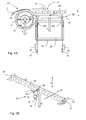
Fig. 2A and Fig. 2B shows an inkjet printing assembly 3 comprising a printsubstrate transport assembly 100 according to the present invention. The inkjet printing assembly 3 further comprises aprint head 4, acarriage 5 and aguide rail 6.Fig. 2A is a side view of the inkjet printing assembly 3 and the printsubstrate transport assembly 100.Fig. 2B is a top plan view of the printsubstrate transport assembly 100 when viewed in a gravity direction g.
The printsubstrate transport assembly 100 comprises aplaten 10 comprising aprint surface 12, afeed roller 20, afeed roller support 30 and aplaten support 40. Theprint surface 12 comprises aprinting area 14. Theprint head 4 is arranged facing saidprinting area 14 and arranged above saidprinting area 14 with respect to the gravity direction g. Theprint head 4 is mounted on thecarriage 5. Thecarriage 5 is movably along theguide rail 6, which extends in a carriage scanning direction (which is perpendicular to the plane of viewing inFig. 2A ). Thefeed roller 20 forms a feed pinch in conjunction withback roller 22. Thefeed roller 20, and as such the feed pinch, is adapted for transporting aprint substrate 2 in a transport direction T of the print substrate along theprint surface 12 and theprinting area 14. Thefeed roller 20 is mounted on anaxle 21 and is driven by a driving means (not shown). As shown inFig. 2B thefeed roller 20 including theaxle 21 and theback roller 22 both extend in a lateral direction W1, which is a lateral direction of the printsubstrate transport assembly 100. Theprint surface 12 extends in a first print surface direction P1 and a second print surface direction P2. Theprinting area 14 is part of theprint surface 12. The first print surface direction P1 is substantially parallel to the lateral direction W1 and the second print surface direction P2 is substantially parallel to the transport direction T. Theprint surface 12 is arranged at a height h1 with respect to the gravity direction g. Said height h1 is selected based on a desired distance to theprint head 4.
Afeed roller support 30 extends in a first support direction S1 and is adapted for adjustably supporting the feed roller in a first adjusting direction as indicated by arrow A1.The first support direction S1 is substantially parallel to the lateral direction W1. The first adjusting direction A1 is substantially parallel and opposite to the gravity direction g. Aplaten support 40 extends in a second support direction S2 and is adapted for adjustably supporting theprint surface 12 in a second adjusting direction which is indicated by arrows A2. The second support direction S2 is substantially parallel to the lateral direction W1. The second adjusting direction A2 is substantially parallel and opposite to the gravity direction g. Both thefeed roller support 30 and theplaten support 40 comprise a box beam structure. The first support direction S1 is substantially parallel to the second support direction S2. In this embodiment thefeed roller support 30 is enclosed by theplaten support 40. Saidfeed roller support 30 is an inner support and saidplaten support 40 is an outer support. Alternatively theplaten support 40 may be enclosed by the feed roller support 30 (not shown).
Theaxle 21 of thefeed roller 20 is supported by thefeed roller support 30 in the gravity direction g (as indicated by arrow A1 inFig. 2A ) at a number of positions along theaxle 21 between a first end 211 and asecond end 212 in the lateral direction W1. In an embodiment theaxle 21 is supported at amiddle portion 213 by thefeed roller support 30.
Theplaten 10, including theprint surface 12 is adjustably supported by theplaten support 40 in the gravity direction g as indicated by arrow A2 inFig. 2A at a plurality of positions along theprint surface 12. The plurality of positions for supporting the print surface may be distributed along the first print surface direction P1 and the second print surface direction P2. -
Fig. 3A and Fig. 3B show an embodiment of the printsubstrate transport assembly 100 according to the present invention.Fig. 3A shows a side view of the embodiment of the printsubstrate transport assembly 100.Fig. 3B shows a perspective view of the embodiment shown inFig. 3A .
InFig. 3A thefeed roller support 30 is connected to theplaten support 40 at a first end in the first support direction S1 via astiff pillar connection 66. Thefeed roller support 30 is expandable in the first support direction S1 at asecond end 31 as indicated by arrow E1, wherein thesecond end 31 is opposite to the first end in the first support direction S1. Thesecond end 31 is expandable in the first support direction S1 independently of theplaten support 40.
Fig. 3B shows a perspective view of an embodiment of the printsubstrate transport assembly 100 according to the present invention. InFig. 3B afirst frame element 50 and abridge structure 60 is shown. Thebridge structure 60 comprises two leaf springs 65 afirst bridge element 61 and asecond bridge element 63. Thefirst bridge element 61 comprises a plurality of connection holes 62 for fixing thesecond end 31 of thefeed roller support 30 to thebridge structure 60. Thesecond bridge element 63 comprises a plurality of connection holes 64 for fixing theplaten support 40 to thebridge structure 60.
The leaf springs 65 connect thefirst bridge element 61 to thesecond bridge element 63. Each of the leaf springs 65 extends perpendicular to the first support direction S1 and the second support direction S2. In particular each of the leaf springs 65 extends substantially in the second direction T and the gravity direction g in between thefirst bridge element 61 and thesecond bridge element 63. The leaf springs 65 are arranged substantially parallel to each other. In case thefirst end 31 of thefeed roller support 30 moves in a direction S1, thefirst bridge element 61 may move in the direction S1 substantially unhindered due to the flexible deformation of bothleaf springs 65 in the direction S1. -
Fig. 4A and Fig. 4B show an embodiment of the printsubstrate transport assembly 100 according to the present invention.Fig. 4A shows a side view of the embodiment of the printsubstrate transport assembly 100.Fig. 4B shows a perspective view of the embodiment shown infig. 4A .
InFig. 4A thefeed roller support 30 comprises afirst suspension structure 32. Thefirst suspension structure 32 is adapted for connecting thefeed roller support 30 to theaxle 21 of thefeed roller 20 and is further adapted for positioning thefeed roller 20 with respect to thefeed roller support 30. Thefirst suspension structure 32 comprises acantilever element 33, twoframe elements first adjusting elements
Thecantilever element 33 extends in the transport direction T between thefeed roller 20 and thefeed roller support 30 and supports theaxle 21 at afirst end 331. As shown inFig. 4B thecantilever element 33 is connected to theaxle 21 at a middle portion of thefeed roller 20. Thefeed roller 20 is further supported by afirst frame element 50 at a first end and is supported by asecond frame element 52 at a second end in the lateral direction W1.
Thecantilever element 33 is supported by the twofirst adjusting elements frame elements feed roller support 30 and protrudes downwards in the gravity direction g from thefeed roller support 30, thereby freely passing through openings of theplaten support 40. On a lower end of each of the twoframe elements 35, 37 a correspondingfirst adjustment element first adjustment elements cantilever element 33 thereby freely passing through openings of theplaten support 40. Thefirst adjusting element 34 shown inFig. 4A and Fig. 4B is connected to an end part of thecantilever element 332, while the other first adjustingelement 36 is connected to an intermediate part of thecantilever element 333.
Theplaten support 40 comprises holes (not shown) for freely letting pass bothfirst adjustment elements frame elements first suspension structure 32 is not connected to and not obstructed by theplaten support 40.
Each of the first adjustingelement cantilever element 33 in the first adjusting direction A1 with respect to thefeed roller support 30. Accordingly thefeed roller 20 may be adjustably positioned in the first adjusting direction A1 with respect to thefeed roller support 30. The first adjusting direction A1 is substantially parallel to the gravity direction g. Possible structures of the first adjustingelement element Fig. 6 .
Both first adjustingelement cantilever 33 in the first adjusting direction A1. Alternatively only one of the first adjustingelement corresponding end part 332 orintermediate part 333 of thecantilever element 33 in the first adjusting direction A1. Depending on the relative positions of theend part 332 and theintermediate part 333 of the cantilever relative to each other and with respect to theaxle 21, theaxle 21 will be positioned in the first adjusting direction A1. Furthermore thecantilever element 33 may be tilted around the lateral direction Wi in case the position of theend part 332 and theintermediate part 333 of thecantilever element 33 are adjusted differently in the first adjusting direction A1.
In an alternative embodiment a plurality offirst suspension structures 32 may be connected to thefeed roller support 30 at distributed positions along the first support direction S1 (not shown), each of the plurality offirst suspension structures 32 being connected to a corresponding portion of thefeed roller 20 along the lateral direction W1 of thefeed roller 20. As such said respective portions of thefeed roller 20 may be adjustably positioned with respect to thefeed roller support 30 independently of each other. - Additionally in an embodiment a transport
gap adjusting element 38 may be provided (shown inFig, 4B ). The transportadjusting gap element 38 is mounted to thecantilever element 33 of thefirst suspension structure 32 at one end of the transportgap adjusting element 38. As a result the transportgap adjusting element 38 is connected to theaxle 21 of thefeed roller 20 via thecantilever element 33. The transportgap adjusting element 38 is mounted on abase part 105 of the platen 10 (shown inFig. 4A ) at another end of the transportgap adjusting element 38. The transportgap adjusting element 38 is adapted for adjustably positioning thefeed roller 20 in the transport direction T with respect to theprint surface 12. An example of a structure of the transportadjusting gap element 38 is shown inFig. 6 . Any vibrations of the feed roller, such as vibrations generated during rotational movements of the feed roller, are not transmitted to the platen by the transport gap adjusting element in a direction perpendicular to the print surface, The advantage is that a position of the print surface perpendicular to the transport direction is not disturbed by vibrations of the feed roller.
In an embodiment the transportgap adjusting element 38 may be provided together with at least one of thefirst adjustment elements Fig. 4B . The advantage is that a distance between thefeed roller 20 and theprint surface 12 in the transport direction T may be controlled using the transportgap adjusting element 38 independently of adjustments of the position of the feed roller in the first adjusting direction A1 using thefirst adjustment elements -
Fig. 5A and Fig. 5B show an embodiment of the printsubstrate transport assembly 100 according to the present invention.Fig. 5A shows a side view of the embodiment of the printsubstrate transport assembly 100. InFig. 5A aplaten support 40 is shown, which encloses afeed roller support 30.Fig. 5B shows a perspective view of the embodiment shown infig. 5A showingsecond suspensions structures platen support 40.
Fig. 5A shows two of thesecond suspension structures second suspension structures platen support 40 to theplaten 10. Each of thesecond suspension structures second adjustment element second adjustment element 44 is connected to theplaten support 40 and connected to a firsttransport end portion 101 of theprint surface 12, while the othersecond adjustment element 45 is connected to theplaten support 40 and connected to a second transport end portion 103of theprint surface 12. The firsttransport end portion 101 of theprint surface 12 is positioned at a first end of theprint surface 12 in the transport direction T, while the secondtransport end portion 103 of theprint surface 12 is positioned at a second end of the print surface opposite to the first end of theprint surface 12 in the transport direction T.
Bothsecond adjusting element Fig. 5A may be adjusted cooperatively in order to adjust the position of theprint surface 12 in a second adjusting direction A2. Alternatively only one of thesecond adjusting element transport end portion 101 or secondtransport end portion 103 of theprint surface 12 with respect to theplaten support 40 in the second adjusting direction A2. - As shown in
Fig. 5B fivesecond suspensions structures print surface 12 in a first print surface direction P1 at each end of theprint surface 12 in the transport direction T. Each of thesuspension structures second adjustment element print surface 12 in a second adjusting direction A2 with respect to theplaten support 40. -
Fig. 6 shows an example of an adjusting element for adjustably positioning an object with respect to a reference element. Said adjusting element may be used as a first adjusting element, a second adjusting element or a transport adjusting element. The adjustingelement 600 comprises ahinge plate 602, havingelastic hinges hinge plate 602 where the width thereof is reduced, and comprise at least onelever 606 adapted to push and/or pull the hinge plate in longitudinal direction L1 thereof, with elastic deflection of at least one of thehinges elastic hinge 603 is arranged near one end of thehinge plate 602, which end is fixed to the adjustinglever 606 at aconnection 609. The otherelastic hinge 604 is arranged near another end of thehinge plate 602, which end is fixed to the connectingpoint 609. Said connectingpoint 609 is moved in the longitudinal direction L1 in association with the movement of thehinge plate 602. Thelever 606 is fixed to an adjustingscrew 608 on one end while being connected to ametal link 610 on another end via ahinge 607. Thehinge 607 is arranged lateral offset to the connectingpoint 609 of thelever 606 to thehinge plate 602.
Themetal link 610 is fixated byfixation points screw 608 is fixed to themetal link 610. Thelever 606 is moved at said on end in the direction L2 by adjusting the adjustingscrew 608. As a result the other end of thelever 606 is moved in the direction L1, in opposite direction to the direction L2, thereby moving thehinge plate 602 in the direction L1. Due to the position of thehinge 607 and the length of thelever 606 the movements of theadjustment screw 608 in the direction L2 may be transmitted in larger movements than thehinge plate 602 in the direction L1. -
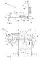
Fig. 7 shows a side view of an embodiment of the printsubstrate transport assembly 100 according to the present invention. InFig. 7a platen support 40 is shown, which encloses afeed roller support 30. The printsubstrate transport assembly 100 further comprises aplaten 10, which comprises aprint surface 12, and afeed roller 20. Thefeed roller 20 forms a feed pinch in conjunction with back roller (not shown). Thefeed roller 20, and as such the feed pinch, is adapted for transporting aprint substrate 2 in a transport direction T of the print substrate along theprint surface 12. Thefeed roller 20 is mounted on anaxle 21 and is driven by a driving means (not shown). Saidfeed roller 20 is arranged upstream if theprint surface 12 in the transport direction T of theprint substrate 2. The feed roller extends in a lateral direction W1 (perpendicular to the plane of viewing).
Thefeed roller support 30 extends in a first support direction S1 (similar as is shown in the embodiment ofFig. 4B ) and is adapted for supporting the feed roller in a first adjusting direction as indicated by arrow A1. The first support direction S1 is substantially parallel to the lateral direction W1. The first adjusting direction A1 is substantially parallel and opposite to the gravity direction g. Theplaten support 40 extends in a second support direction S2 (similar as is shown in the embodiment ofFig. 4B ) and is adapted for supporting theprint surface 12 in a second adjusting direction which is indicated by arrows A2. The second support direction S2 is substantially parallel to the lateral direction W1. The second adjusting direction A2 is substantially parallel and opposite to the gravity direction g. Both thefeed roller support 30 and theplaten support 40 comprise a box beam structure.
Theprint surface 12 comprises a plurality of suction holes 72. Said suction holes 72 are distributed over theprinting surface 12. The suction holes are adapted for communicating an air pressure to theprint substrate 2 in order to hold down theprint substrate 2 in contact with theprint surface 12. The printsubstrate transport assembly 100 further comprises anair pressure source 70. Theair pressure source 70 is a vacuum source, which is adapted for providing a vacuum air pressure for holding theprint substrate 2 in contact with theprint surface 12. Theair pressure source 70 is mounted to and enclosed by thefeed roller support 30. Theair pressure source 70 is operatively coupled to the plurality of suction holes 72 via aflexible hose 74. Theflexible hose 74 communicates the vacuum air pressure to the suction holes 72. In case theair pressure source 70 generates vibrations, said vibrations are absorbed by thefeed roller support 30 and are not transmitted to theprint surface 12. Transmittance of the vibrations towards thefeed roller 20 are prevented or at least attenuated by thefirst suspension structure 32 and theflexible hose 74. For example thefirst adjusting elements air pressure source 70 is fully mechanically decoupled from theprint surface 12 and is partially mechanically decoupled from thefeed roller 20.
Furthermore by mounting theair pressure source 70 inside thefeed roller support 30, it may be arranged close to the suction holes 72 and theprint surface 12, thereby reducing any loss of vacuum pressure. - Detailed embodiments of the present invention are disclosed herein; however, it is to be understood that the disclosed embodiments are merely exemplary of the invention, which can be embodied in various forms. Therefore, specific structural and functional details disclosed herein are not to be interpreted as limiting, but merely as a basis for the claims and as a representative basis for teaching one skilled in the art to variously employ the present invention in virtually any appropriately detailed structure. In particular, features presented and described in separate dependent claims may be applied in combination and any advantageous combination of such claims is herewith disclosed.
Further, the terms and phrases used herein are not intended to be limiting; but rather, to provide an understandable description of the invention. The terms "a" or "an", as used herein, are defined as one or more than one. The term plurality, as used herein, is defined as two or more than two. The term another, as used herein, is defined as at least a second or more. The terms including and/or having, as used herein, are defined as comprising (i.e., open language). The term coupled, as used herein, is defined as connected, although not necessarily directly.
The invention being thus described, it will be obvious that the same may be varied in many ways. Such variations are not to be regarded as a departure from the spirit and scope of the invention, and all such modifications as would be obvious to one skilled in the art are intended to be included within the scope of the following claims.
Claims (15)
- A print substrate transport assembly for transporting a print substrate in a printing apparatus, comprising a feed roller for transporting the print substrate, a platen for supporting said print substrate, a feed roller support for supporting said feed roller and a platen support for supporting said platen;
wherein the platen comprises a print surface to support the print substrate; wherein the feed roller comprises an axle which is arranged for transporting the print substrate in a transport direction along the print surface;
wherein the feed roller support extends in a first support direction, which is directed along the axle of the feed roller, the feed roller support being adapted for adjustably positioning the feed roller in a first adjusting direction, which first adjusting direction is substantially perpendicular to the print surface;
wherein the platen support extends in a second support direction, the platen support being adapted for adjustably positioning said platen in a second adjusting direction, which second adjusting direction is substantially perpendicular to the print surface;
wherein the print substrate transport assembly comprises an inner support which is at least partly enclosed by an outer support, wherein said inner support is one selected from the feed roller support and the platen support and wherein said outer support is an other selected from the feed roller support and the platen support; and
wherein said outer support defines an enclosed volume, and wherein a suspension structure of the inner support, which connects the inner support to the corresponding feed roller or platen, extends outside of the enclosed volume. - The print substrate transport assembly according to claim 1, wherein said inner support is expandable in the respective first support direction or second support direction independently of said outer support.
- The print substrate transport assembly according to claim 2, wherein a first end of said inner support is connected to a first end of said outer support by means of at least one leaf spring, wherein each of said at least one leaf spring is extending substantially perpendicular to the respective first support direction or second support direction.
- The print substrate transport assembly according to claim 1, wherein the feed roller support comprises a first suspension structure connected to the feed roller, wherein the first suspension structure comprises a first adjusting element adapted for adjustably positioning the feed roller in the first adjusting direction with respect to the feed roller support.
- The print substrate transport assembly according to claim 1, wherein the platen support comprises a plurality of second suspension structures being connected to the platen, each comprising a second adjusting element, wherein each of the second adjusting elements is adapted for adjustably positioning the print surface in the second adjusting direction with respect to the platen support.
- The print substrate transport assembly according to claim 5, wherein at least one of the second suspension structures of the platen support is adapted to adjustably position a first transport end portion of the print surface with respect to the platen support and wherein at least another one of the second suspension structures of the platen support is adapted to adjustably position a second transport end portion of the print surface with respect to the platen support, which second transport end portion is arranged opposite to the first transport end portion with respect to the transport direction.
- The print substrate transport assembly according to claim 4, wherein the print substrate transport assembly further comprises a transport gap adjusting element, which transport gap adjusting element is mounted to the feed roller and to one of the platen and the feed roller support, the transport gap adjusting element being adapted for adjustably positioning the feed roller in the transport direction with respect to the print surface.
- The print substrate transport assembly according to claim 7, wherein said transport gap adjusting element is part of the first suspension structure, which is mounted to the feed roller support, and is adapted for adjustably positioning the feed roller in the transport direction with respect to the print surface independently of said first adjusting element adjustably positioning the feed roller in the first adjusting direction with respect to the feed roller support.
- The print substrate transport assembly according to claim 4, wherein the first suspension structure comprises a cantilever element, which cantilever element extends in a direction substantially perpendicular to the first adjusting direction and is connected to the feed roller near one end of the cantilever element, wherein said first adjusting element is connected to the feed roller support at one end and connected to the cantilever element at another end of said first adjusting element in the first adjusting direction.
- The print substrate transport assembly according to claim 1, wherein the inner support is said feed roller support and the outer support is said platen support.
- The print substrate transport assembly according to claim 1, wherein said supension structure of the inner support is disposed partly within the enclosed volume defined by the outer support.
- The print substrate transport assembly according to claim 1, wherein the print surface comprises a plurality of suction holes and wherein the print substrate transport assembly further comprises an air pressure source, wherein said air pressure source is mounted onto said inner support and said air pressure source is operatively coupled to the plurality of suction holes for providing an air pressure to the print substrate.
- A printing system, comprising the print substrate transport assembly according to any one of the preceding claims, further comprising a print head, wherein said print surface comprising a print area and wherein the print head is adapted for in printing operation applying an image on the print substrate in the printing area.
- The printing system according to claim 13, wherein the print head comprises a nozzle plate surface, and wherein the position of the print surface is adjusted in the second adjusting direction based on a desired distance between the print surface and the nozzle plate surface in the second adjusting direction.
- The printing system according to claim 13, wherein the printing system further comprising a guide rail and a carriage , wherein the guide rail extends in a carriage scanning direction, wherein the print head is mounted on the carriage, wherein the carriage is guided in the carriage scanning direction over the print surface by means of the guide rail wherein the carriage scanning direction is substantially perpendicular to the transport direction.
Priority Applications (1)
| Application Number | Priority Date | Filing Date | Title |
|---|---|---|---|
| EP14182329.4A EP2990364B1 (en) | 2014-08-26 | 2014-08-26 | Print substrate transport assembly |
Applications Claiming Priority (1)
| Application Number | Priority Date | Filing Date | Title |
|---|---|---|---|
| EP14182329.4A EP2990364B1 (en) | 2014-08-26 | 2014-08-26 | Print substrate transport assembly |
Publications (2)
| Publication Number | Publication Date |
|---|---|
| EP2990364A1 true EP2990364A1 (en) | 2016-03-02 |
| EP2990364B1 EP2990364B1 (en) | 2017-05-31 |
Family
ID=51399534
Family Applications (1)
| Application Number | Title | Priority Date | Filing Date |
|---|---|---|---|
| EP14182329.4A Not-in-force EP2990364B1 (en) | 2014-08-26 | 2014-08-26 | Print substrate transport assembly |
Country Status (1)
| Country | Link |
|---|---|
| EP (1) | EP2990364B1 (en) |
Cited By (1)
| Publication number | Priority date | Publication date | Assignee | Title |
|---|---|---|---|---|
| US10773533B1 (en) | 2019-03-11 | 2020-09-15 | Citizen Watch Co., Ltd. | Printer |
Citations (3)
| Publication number | Priority date | Publication date | Assignee | Title |
|---|---|---|---|---|
| EP1642735A1 (en) * | 2004-10-04 | 2006-04-05 | Océ-Technologies B.V. | Sheet handling device for wide format sheets |
| US20080143032A1 (en) * | 2006-12-17 | 2008-06-19 | Matan Digital Printers Ltd. | Dual Mode Printer |
| US20110311294A1 (en) * | 2010-06-17 | 2011-12-22 | Brother Kogyo Kabushiki Kaisha | Image recording apparatus |
-
2014
- 2014-08-26 EP EP14182329.4A patent/EP2990364B1/en not_active Not-in-force
Patent Citations (3)
| Publication number | Priority date | Publication date | Assignee | Title |
|---|---|---|---|---|
| EP1642735A1 (en) * | 2004-10-04 | 2006-04-05 | Océ-Technologies B.V. | Sheet handling device for wide format sheets |
| US20080143032A1 (en) * | 2006-12-17 | 2008-06-19 | Matan Digital Printers Ltd. | Dual Mode Printer |
| US20110311294A1 (en) * | 2010-06-17 | 2011-12-22 | Brother Kogyo Kabushiki Kaisha | Image recording apparatus |
Cited By (2)
| Publication number | Priority date | Publication date | Assignee | Title |
|---|---|---|---|---|
| US10773533B1 (en) | 2019-03-11 | 2020-09-15 | Citizen Watch Co., Ltd. | Printer |
| JP2020146843A (en) * | 2019-03-11 | 2020-09-17 | シチズン時計株式会社 | Printer |
Also Published As
| Publication number | Publication date |
|---|---|
| EP2990364B1 (en) | 2017-05-31 |
Similar Documents
| Publication | Publication Date | Title |
|---|---|---|
| US20140247309A1 (en) | Inkjet print head and method for manufacturing such print head | |
| JP7275604B2 (en) | Mobile object, equipment for ejecting liquid | |
| US9592685B2 (en) | Scanning inkjet printing system | |
| US9840098B2 (en) | Printer for printing on a medium | |
| US9718291B2 (en) | Printer carriage support structure | |
| US9434161B2 (en) | Print head unit | |
| US9862213B2 (en) | Scanning inkjet printing system | |
| EP3222433B1 (en) | Print head support assembly and inkjet printer comprising such assembly | |
| EP3366481B1 (en) | Printing system with a blouse forming device for stiff web media | |
| EP2990364B1 (en) | Print substrate transport assembly | |
| US10343430B2 (en) | Assembly for moving a carriage | |
| US20200001633A1 (en) | Dancer suspension assembly for a roll-to-roll printer | |
| US20180086584A1 (en) | Web transport assembly for transporting a web along a processing unit | |
| US8678564B2 (en) | Inkjet print head | |
| EP2949476A1 (en) | Image forming apparatus and method to compensate wobble of a roll in an image forming apparatus | |
| US20120229564A1 (en) | Inkjet print head wiper for partially wetting and anti-wetting nozzle surfaces, cleaning unit and an inkjet printer comprising said wiper | |
| EP1574348A1 (en) | Tensioning system for printing devices |
Legal Events
| Date | Code | Title | Description |
|---|---|---|---|
| PUAI | Public reference made under article 153(3) epc to a published international application that has entered the european phase |
Free format text: ORIGINAL CODE: 0009012 |
|
| AK | Designated contracting states |
Kind code of ref document: A1 Designated state(s): AL AT BE BG CH CY CZ DE DK EE ES FI FR GB GR HR HU IE IS IT LI LT LU LV MC MK MT NL NO PL PT RO RS SE SI SK SM TR |
|
| AX | Request for extension of the european patent |
Extension state: BA ME |
|
| 17P | Request for examination filed |
Effective date: 20160902 |
|
| RBV | Designated contracting states (corrected) |
Designated state(s): AL AT BE BG CH CY CZ DE DK EE ES FI FR GB GR HR HU IE IS IT LI LT LU LV MC MK MT NL NO PL PT RO RS SE SI SK SM TR |
|
| GRAP | Despatch of communication of intention to grant a patent |
Free format text: ORIGINAL CODE: EPIDOSNIGR1 |
|
| STAA | Information on the status of an ep patent application or granted ep patent |
Free format text: STATUS: GRANT OF PATENT IS INTENDED |
|
| INTG | Intention to grant announced |
Effective date: 20170102 |
|
| GRAS | Grant fee paid |
Free format text: ORIGINAL CODE: EPIDOSNIGR3 |
|
| GRAA | (expected) grant |
Free format text: ORIGINAL CODE: 0009210 |
|
| STAA | Information on the status of an ep patent application or granted ep patent |
Free format text: STATUS: THE PATENT HAS BEEN GRANTED |
|
| AK | Designated contracting states |
Kind code of ref document: B1 Designated state(s): AL AT BE BG CH CY CZ DE DK EE ES FI FR GB GR HR HU IE IS IT LI LT LU LV MC MK MT NL NO PL PT RO RS SE SI SK SM TR |
|
| REG | Reference to a national code |
Ref country code: CH Ref legal event code: EP Ref country code: GB Ref legal event code: FG4D |
|
| REG | Reference to a national code |
Ref country code: AT Ref legal event code: REF Ref document number: 897247 Country of ref document: AT Kind code of ref document: T Effective date: 20170615 |
|
| REG | Reference to a national code |
Ref country code: IE Ref legal event code: FG4D |
|
| REG | Reference to a national code |
Ref country code: DE Ref legal event code: R096 Ref document number: 602014010216 Country of ref document: DE |
|
| REG | Reference to a national code |
Ref country code: FR Ref legal event code: PLFP Year of fee payment: 4 |
|
| REG | Reference to a national code |
Ref country code: NL Ref legal event code: FP |
|
| REG | Reference to a national code |
Ref country code: LT Ref legal event code: MG4D |
|
| REG | Reference to a national code |
Ref country code: AT Ref legal event code: MK05 Ref document number: 897247 Country of ref document: AT Kind code of ref document: T Effective date: 20170531 |
|
| PG25 | Lapsed in a contracting state [announced via postgrant information from national office to epo] |
Ref country code: ES Free format text: LAPSE BECAUSE OF FAILURE TO SUBMIT A TRANSLATION OF THE DESCRIPTION OR TO PAY THE FEE WITHIN THE PRESCRIBED TIME-LIMIT Effective date: 20170531 Ref country code: GR Free format text: LAPSE BECAUSE OF FAILURE TO SUBMIT A TRANSLATION OF THE DESCRIPTION OR TO PAY THE FEE WITHIN THE PRESCRIBED TIME-LIMIT Effective date: 20170901 Ref country code: NO Free format text: LAPSE BECAUSE OF FAILURE TO SUBMIT A TRANSLATION OF THE DESCRIPTION OR TO PAY THE FEE WITHIN THE PRESCRIBED TIME-LIMIT Effective date: 20170831 Ref country code: HR Free format text: LAPSE BECAUSE OF FAILURE TO SUBMIT A TRANSLATION OF THE DESCRIPTION OR TO PAY THE FEE WITHIN THE PRESCRIBED TIME-LIMIT Effective date: 20170531 Ref country code: FI Free format text: LAPSE BECAUSE OF FAILURE TO SUBMIT A TRANSLATION OF THE DESCRIPTION OR TO PAY THE FEE WITHIN THE PRESCRIBED TIME-LIMIT Effective date: 20170531 Ref country code: AT Free format text: LAPSE BECAUSE OF FAILURE TO SUBMIT A TRANSLATION OF THE DESCRIPTION OR TO PAY THE FEE WITHIN THE PRESCRIBED TIME-LIMIT Effective date: 20170531 Ref country code: LT Free format text: LAPSE BECAUSE OF FAILURE TO SUBMIT A TRANSLATION OF THE DESCRIPTION OR TO PAY THE FEE WITHIN THE PRESCRIBED TIME-LIMIT Effective date: 20170531 |
|
| PG25 | Lapsed in a contracting state [announced via postgrant information from national office to epo] |
Ref country code: BG Free format text: LAPSE BECAUSE OF FAILURE TO SUBMIT A TRANSLATION OF THE DESCRIPTION OR TO PAY THE FEE WITHIN THE PRESCRIBED TIME-LIMIT Effective date: 20170831 Ref country code: SE Free format text: LAPSE BECAUSE OF FAILURE TO SUBMIT A TRANSLATION OF THE DESCRIPTION OR TO PAY THE FEE WITHIN THE PRESCRIBED TIME-LIMIT Effective date: 20170531 Ref country code: IS Free format text: LAPSE BECAUSE OF FAILURE TO SUBMIT A TRANSLATION OF THE DESCRIPTION OR TO PAY THE FEE WITHIN THE PRESCRIBED TIME-LIMIT Effective date: 20170930 Ref country code: RS Free format text: LAPSE BECAUSE OF FAILURE TO SUBMIT A TRANSLATION OF THE DESCRIPTION OR TO PAY THE FEE WITHIN THE PRESCRIBED TIME-LIMIT Effective date: 20170531 Ref country code: LV Free format text: LAPSE BECAUSE OF FAILURE TO SUBMIT A TRANSLATION OF THE DESCRIPTION OR TO PAY THE FEE WITHIN THE PRESCRIBED TIME-LIMIT Effective date: 20170531 |
|
| PG25 | Lapsed in a contracting state [announced via postgrant information from national office to epo] |
Ref country code: SK Free format text: LAPSE BECAUSE OF FAILURE TO SUBMIT A TRANSLATION OF THE DESCRIPTION OR TO PAY THE FEE WITHIN THE PRESCRIBED TIME-LIMIT Effective date: 20170531 Ref country code: EE Free format text: LAPSE BECAUSE OF FAILURE TO SUBMIT A TRANSLATION OF THE DESCRIPTION OR TO PAY THE FEE WITHIN THE PRESCRIBED TIME-LIMIT Effective date: 20170531 Ref country code: DK Free format text: LAPSE BECAUSE OF FAILURE TO SUBMIT A TRANSLATION OF THE DESCRIPTION OR TO PAY THE FEE WITHIN THE PRESCRIBED TIME-LIMIT Effective date: 20170531 Ref country code: RO Free format text: LAPSE BECAUSE OF FAILURE TO SUBMIT A TRANSLATION OF THE DESCRIPTION OR TO PAY THE FEE WITHIN THE PRESCRIBED TIME-LIMIT Effective date: 20170531 Ref country code: CZ Free format text: LAPSE BECAUSE OF FAILURE TO SUBMIT A TRANSLATION OF THE DESCRIPTION OR TO PAY THE FEE WITHIN THE PRESCRIBED TIME-LIMIT Effective date: 20170531 |
|
| PG25 | Lapsed in a contracting state [announced via postgrant information from national office to epo] |
Ref country code: IT Free format text: LAPSE BECAUSE OF FAILURE TO SUBMIT A TRANSLATION OF THE DESCRIPTION OR TO PAY THE FEE WITHIN THE PRESCRIBED TIME-LIMIT Effective date: 20170531 Ref country code: SM Free format text: LAPSE BECAUSE OF FAILURE TO SUBMIT A TRANSLATION OF THE DESCRIPTION OR TO PAY THE FEE WITHIN THE PRESCRIBED TIME-LIMIT Effective date: 20170531 Ref country code: PL Free format text: LAPSE BECAUSE OF FAILURE TO SUBMIT A TRANSLATION OF THE DESCRIPTION OR TO PAY THE FEE WITHIN THE PRESCRIBED TIME-LIMIT Effective date: 20170531 |
|
| REG | Reference to a national code |
Ref country code: DE Ref legal event code: R097 Ref document number: 602014010216 Country of ref document: DE |
|
| REG | Reference to a national code |
Ref country code: CH Ref legal event code: PL |
|
| PG25 | Lapsed in a contracting state [announced via postgrant information from national office to epo] |
Ref country code: MC Free format text: LAPSE BECAUSE OF FAILURE TO SUBMIT A TRANSLATION OF THE DESCRIPTION OR TO PAY THE FEE WITHIN THE PRESCRIBED TIME-LIMIT Effective date: 20170531 |
|
| PLBE | No opposition filed within time limit |
Free format text: ORIGINAL CODE: 0009261 |
|
| STAA | Information on the status of an ep patent application or granted ep patent |
Free format text: STATUS: NO OPPOSITION FILED WITHIN TIME LIMIT |
|
| PG25 | Lapsed in a contracting state [announced via postgrant information from national office to epo] |
Ref country code: CH Free format text: LAPSE BECAUSE OF NON-PAYMENT OF DUE FEES Effective date: 20170831 Ref country code: LI Free format text: LAPSE BECAUSE OF NON-PAYMENT OF DUE FEES Effective date: 20170831 |
|
| REG | Reference to a national code |
Ref country code: BE Ref legal event code: MM Effective date: 20170831 |
|
| 26N | No opposition filed |
Effective date: 20180301 |
|
| REG | Reference to a national code |
Ref country code: IE Ref legal event code: MM4A |
|
| PG25 | Lapsed in a contracting state [announced via postgrant information from national office to epo] |
Ref country code: SI Free format text: LAPSE BECAUSE OF FAILURE TO SUBMIT A TRANSLATION OF THE DESCRIPTION OR TO PAY THE FEE WITHIN THE PRESCRIBED TIME-LIMIT Effective date: 20170531 |
|
| PG25 | Lapsed in a contracting state [announced via postgrant information from national office to epo] |
Ref country code: LU Free format text: LAPSE BECAUSE OF NON-PAYMENT OF DUE FEES Effective date: 20170826 |
|
| PG25 | Lapsed in a contracting state [announced via postgrant information from national office to epo] |
Ref country code: IE Free format text: LAPSE BECAUSE OF NON-PAYMENT OF DUE FEES Effective date: 20170826 |
|
| REG | Reference to a national code |
Ref country code: FR Ref legal event code: PLFP Year of fee payment: 5 |
|
| PG25 | Lapsed in a contracting state [announced via postgrant information from national office to epo] |
Ref country code: BE Free format text: LAPSE BECAUSE OF NON-PAYMENT OF DUE FEES Effective date: 20170831 |
|
| PG25 | Lapsed in a contracting state [announced via postgrant information from national office to epo] |
Ref country code: MT Free format text: LAPSE BECAUSE OF NON-PAYMENT OF DUE FEES Effective date: 20170826 |
|
| PGFP | Annual fee paid to national office [announced via postgrant information from national office to epo] |
Ref country code: NL Payment date: 20180823 Year of fee payment: 5 Ref country code: FR Payment date: 20180827 Year of fee payment: 5 Ref country code: DE Payment date: 20180823 Year of fee payment: 5 |
|
| PGFP | Annual fee paid to national office [announced via postgrant information from national office to epo] |
Ref country code: GB Payment date: 20180822 Year of fee payment: 5 |
|
| PG25 | Lapsed in a contracting state [announced via postgrant information from national office to epo] |
Ref country code: HU Free format text: LAPSE BECAUSE OF FAILURE TO SUBMIT A TRANSLATION OF THE DESCRIPTION OR TO PAY THE FEE WITHIN THE PRESCRIBED TIME-LIMIT; INVALID AB INITIO Effective date: 20140826 |
|
| PG25 | Lapsed in a contracting state [announced via postgrant information from national office to epo] |
Ref country code: CY Free format text: LAPSE BECAUSE OF FAILURE TO SUBMIT A TRANSLATION OF THE DESCRIPTION OR TO PAY THE FEE WITHIN THE PRESCRIBED TIME-LIMIT Effective date: 20170531 |
|
| PG25 | Lapsed in a contracting state [announced via postgrant information from national office to epo] |
Ref country code: MK Free format text: LAPSE BECAUSE OF FAILURE TO SUBMIT A TRANSLATION OF THE DESCRIPTION OR TO PAY THE FEE WITHIN THE PRESCRIBED TIME-LIMIT Effective date: 20170531 |
|
| REG | Reference to a national code |
Ref country code: DE Ref legal event code: R119 Ref document number: 602014010216 Country of ref document: DE |
|
| PG25 | Lapsed in a contracting state [announced via postgrant information from national office to epo] |
Ref country code: TR Free format text: LAPSE BECAUSE OF FAILURE TO SUBMIT A TRANSLATION OF THE DESCRIPTION OR TO PAY THE FEE WITHIN THE PRESCRIBED TIME-LIMIT Effective date: 20170531 |
|
| REG | Reference to a national code |
Ref country code: NL Ref legal event code: MM Effective date: 20190901 |
|
| GBPC | Gb: european patent ceased through non-payment of renewal fee |
Effective date: 20190826 |
|
| PG25 | Lapsed in a contracting state [announced via postgrant information from national office to epo] |
Ref country code: PT Free format text: LAPSE BECAUSE OF FAILURE TO SUBMIT A TRANSLATION OF THE DESCRIPTION OR TO PAY THE FEE WITHIN THE PRESCRIBED TIME-LIMIT Effective date: 20170531 |
|
| PG25 | Lapsed in a contracting state [announced via postgrant information from national office to epo] |
Ref country code: FR Free format text: LAPSE BECAUSE OF NON-PAYMENT OF DUE FEES Effective date: 20190831 Ref country code: DE Free format text: LAPSE BECAUSE OF NON-PAYMENT OF DUE FEES Effective date: 20200303 Ref country code: AL Free format text: LAPSE BECAUSE OF FAILURE TO SUBMIT A TRANSLATION OF THE DESCRIPTION OR TO PAY THE FEE WITHIN THE PRESCRIBED TIME-LIMIT Effective date: 20170531 Ref country code: NL Free format text: LAPSE BECAUSE OF NON-PAYMENT OF DUE FEES Effective date: 20190901 |
|
| PG25 | Lapsed in a contracting state [announced via postgrant information from national office to epo] |
Ref country code: GB Free format text: LAPSE BECAUSE OF NON-PAYMENT OF DUE FEES Effective date: 20190826 |