EP2990215A1 - Protective cover and bearing device including protective cover - Google Patents
Protective cover and bearing device including protective cover Download PDFInfo
- Publication number
- EP2990215A1 EP2990215A1 EP15181742.6A EP15181742A EP2990215A1 EP 2990215 A1 EP2990215 A1 EP 2990215A1 EP 15181742 A EP15181742 A EP 15181742A EP 2990215 A1 EP2990215 A1 EP 2990215A1
- Authority
- EP
- European Patent Office
- Prior art keywords
- protective cover
- outer ring
- magnetic encoder
- magnetic
- inner ring
- Prior art date
- Legal status (The legal status is an assumption and is not a legal conclusion. Google has not performed a legal analysis and makes no representation as to the accuracy of the status listed.)
- Withdrawn
Links
Images


Classifications
-
- B—PERFORMING OPERATIONS; TRANSPORTING
- B60—VEHICLES IN GENERAL
- B60B—VEHICLE WHEELS; CASTORS; AXLES FOR WHEELS OR CASTORS; INCREASING WHEEL ADHESION
- B60B27/00—Hubs
- B60B27/0073—Hubs characterised by sealing means
-
- B—PERFORMING OPERATIONS; TRANSPORTING
- B60—VEHICLES IN GENERAL
- B60B—VEHICLE WHEELS; CASTORS; AXLES FOR WHEELS OR CASTORS; INCREASING WHEEL ADHESION
- B60B7/00—Wheel cover discs, rings, or the like, for ornamenting, protecting, venting, or obscuring, wholly or in part, the wheel body, rim, hub, or tyre sidewall, e.g. wheel cover discs, wheel cover discs with cooling fins
- B60B7/0013—Hub caps
-
- B—PERFORMING OPERATIONS; TRANSPORTING
- B60—VEHICLES IN GENERAL
- B60B—VEHICLE WHEELS; CASTORS; AXLES FOR WHEELS OR CASTORS; INCREASING WHEEL ADHESION
- B60B27/00—Hubs
- B60B27/0005—Hubs with ball bearings
-
- B—PERFORMING OPERATIONS; TRANSPORTING
- B60—VEHICLES IN GENERAL
- B60B—VEHICLE WHEELS; CASTORS; AXLES FOR WHEELS OR CASTORS; INCREASING WHEEL ADHESION
- B60B27/00—Hubs
- B60B27/0047—Hubs characterised by functional integration of other elements
- B60B27/0068—Hubs characterised by functional integration of other elements the element being a sensor
-
- F—MECHANICAL ENGINEERING; LIGHTING; HEATING; WEAPONS; BLASTING
- F16—ENGINEERING ELEMENTS AND UNITS; GENERAL MEASURES FOR PRODUCING AND MAINTAINING EFFECTIVE FUNCTIONING OF MACHINES OR INSTALLATIONS; THERMAL INSULATION IN GENERAL
- F16C—SHAFTS; FLEXIBLE SHAFTS; ELEMENTS OR CRANKSHAFT MECHANISMS; ROTARY BODIES OTHER THAN GEARING ELEMENTS; BEARINGS
- F16C33/00—Parts of bearings; Special methods for making bearings or parts thereof
- F16C33/72—Sealings
- F16C33/723—Shaft end sealing means, e.g. cup-shaped caps or covers
-
- F—MECHANICAL ENGINEERING; LIGHTING; HEATING; WEAPONS; BLASTING
- F16—ENGINEERING ELEMENTS AND UNITS; GENERAL MEASURES FOR PRODUCING AND MAINTAINING EFFECTIVE FUNCTIONING OF MACHINES OR INSTALLATIONS; THERMAL INSULATION IN GENERAL
- F16C—SHAFTS; FLEXIBLE SHAFTS; ELEMENTS OR CRANKSHAFT MECHANISMS; ROTARY BODIES OTHER THAN GEARING ELEMENTS; BEARINGS
- F16C33/00—Parts of bearings; Special methods for making bearings or parts thereof
- F16C33/72—Sealings
- F16C33/76—Sealings of ball or roller bearings
- F16C33/78—Sealings of ball or roller bearings with a diaphragm, disc, or ring, with or without resilient members
- F16C33/7816—Details of the sealing or parts thereof, e.g. geometry, material
-
- F—MECHANICAL ENGINEERING; LIGHTING; HEATING; WEAPONS; BLASTING
- F16—ENGINEERING ELEMENTS AND UNITS; GENERAL MEASURES FOR PRODUCING AND MAINTAINING EFFECTIVE FUNCTIONING OF MACHINES OR INSTALLATIONS; THERMAL INSULATION IN GENERAL
- F16C—SHAFTS; FLEXIBLE SHAFTS; ELEMENTS OR CRANKSHAFT MECHANISMS; ROTARY BODIES OTHER THAN GEARING ELEMENTS; BEARINGS
- F16C41/00—Other accessories, e.g. devices integrated in the bearing not relating to the bearing function as such
- F16C41/007—Encoders, e.g. parts with a plurality of alternating magnetic poles
-
- G—PHYSICS
- G01—MEASURING; TESTING
- G01D—MEASURING NOT SPECIALLY ADAPTED FOR A SPECIFIC VARIABLE; ARRANGEMENTS FOR MEASURING TWO OR MORE VARIABLES NOT COVERED IN A SINGLE OTHER SUBCLASS; TARIFF METERING APPARATUS; MEASURING OR TESTING NOT OTHERWISE PROVIDED FOR
- G01D5/00—Mechanical means for transferring the output of a sensing member; Means for converting the output of a sensing member to another variable where the form or nature of the sensing member does not constrain the means for converting; Transducers not specially adapted for a specific variable
- G01D5/12—Mechanical means for transferring the output of a sensing member; Means for converting the output of a sensing member to another variable where the form or nature of the sensing member does not constrain the means for converting; Transducers not specially adapted for a specific variable using electric or magnetic means
- G01D5/244—Mechanical means for transferring the output of a sensing member; Means for converting the output of a sensing member to another variable where the form or nature of the sensing member does not constrain the means for converting; Transducers not specially adapted for a specific variable using electric or magnetic means influencing characteristics of pulses or pulse trains; generating pulses or pulse trains
- G01D5/24428—Error prevention
- G01D5/24433—Error prevention by mechanical means
-
- G—PHYSICS
- G01—MEASURING; TESTING
- G01P—MEASURING LINEAR OR ANGULAR SPEED, ACCELERATION, DECELERATION, OR SHOCK; INDICATING PRESENCE, ABSENCE, OR DIRECTION, OF MOVEMENT
- G01P1/00—Details of instruments
- G01P1/02—Housings
- G01P1/026—Housings for speed measuring devices, e.g. pulse generator
-
- G—PHYSICS
- G01—MEASURING; TESTING
- G01P—MEASURING LINEAR OR ANGULAR SPEED, ACCELERATION, DECELERATION, OR SHOCK; INDICATING PRESENCE, ABSENCE, OR DIRECTION, OF MOVEMENT
- G01P3/00—Measuring linear or angular speed; Measuring differences of linear or angular speeds
- G01P3/42—Devices characterised by the use of electric or magnetic means
- G01P3/44—Devices characterised by the use of electric or magnetic means for measuring angular speed
- G01P3/48—Devices characterised by the use of electric or magnetic means for measuring angular speed by measuring frequency of generated current or voltage
- G01P3/481—Devices characterised by the use of electric or magnetic means for measuring angular speed by measuring frequency of generated current or voltage of pulse signals
- G01P3/487—Devices characterised by the use of electric or magnetic means for measuring angular speed by measuring frequency of generated current or voltage of pulse signals delivered by rotating magnets
-
- B—PERFORMING OPERATIONS; TRANSPORTING
- B60—VEHICLES IN GENERAL
- B60B—VEHICLE WHEELS; CASTORS; AXLES FOR WHEELS OR CASTORS; INCREASING WHEEL ADHESION
- B60B2310/00—Manufacturing methods
- B60B2310/30—Manufacturing methods joining
- B60B2310/316—Manufacturing methods joining by press-fitting, shrink-fitting
-
- B—PERFORMING OPERATIONS; TRANSPORTING
- B60—VEHICLES IN GENERAL
- B60B—VEHICLE WHEELS; CASTORS; AXLES FOR WHEELS OR CASTORS; INCREASING WHEEL ADHESION
- B60B2360/00—Materials; Physical forms thereof
- B60B2360/10—Metallic materials
- B60B2360/102—Steel
-
- B—PERFORMING OPERATIONS; TRANSPORTING
- B60—VEHICLES IN GENERAL
- B60B—VEHICLE WHEELS; CASTORS; AXLES FOR WHEELS OR CASTORS; INCREASING WHEEL ADHESION
- B60B27/00—Hubs
-
- B—PERFORMING OPERATIONS; TRANSPORTING
- B60—VEHICLES IN GENERAL
- B60B—VEHICLE WHEELS; CASTORS; AXLES FOR WHEELS OR CASTORS; INCREASING WHEEL ADHESION
- B60B2900/00—Purpose of invention
- B60B2900/10—Reduction of
- B60B2900/121—Resisting forces
- B60B2900/1212—Resisting forces due to friction
-
- B—PERFORMING OPERATIONS; TRANSPORTING
- B60—VEHICLES IN GENERAL
- B60B—VEHICLE WHEELS; CASTORS; AXLES FOR WHEELS OR CASTORS; INCREASING WHEEL ADHESION
- B60B2900/00—Purpose of invention
- B60B2900/20—Avoidance of
- B60B2900/211—Soiling
-
- B—PERFORMING OPERATIONS; TRANSPORTING
- B60—VEHICLES IN GENERAL
- B60B—VEHICLE WHEELS; CASTORS; AXLES FOR WHEELS OR CASTORS; INCREASING WHEEL ADHESION
- B60B2900/00—Purpose of invention
- B60B2900/50—Improvement of
- B60B2900/511—Sealing
-
- B—PERFORMING OPERATIONS; TRANSPORTING
- B60—VEHICLES IN GENERAL
- B60B—VEHICLE WHEELS; CASTORS; AXLES FOR WHEELS OR CASTORS; INCREASING WHEEL ADHESION
- B60B2900/00—Purpose of invention
- B60B2900/90—Providing or changing
- B60B2900/931—Magnetic effects
-
- C—CHEMISTRY; METALLURGY
- C21—METALLURGY OF IRON
- C21D—MODIFYING THE PHYSICAL STRUCTURE OF FERROUS METALS; GENERAL DEVICES FOR HEAT TREATMENT OF FERROUS OR NON-FERROUS METALS OR ALLOYS; MAKING METAL MALLEABLE, e.g. BY DECARBURISATION OR TEMPERING
- C21D2211/00—Microstructure comprising significant phases
- C21D2211/001—Austenite
-
- F—MECHANICAL ENGINEERING; LIGHTING; HEATING; WEAPONS; BLASTING
- F16—ENGINEERING ELEMENTS AND UNITS; GENERAL MEASURES FOR PRODUCING AND MAINTAINING EFFECTIVE FUNCTIONING OF MACHINES OR INSTALLATIONS; THERMAL INSULATION IN GENERAL
- F16C—SHAFTS; FLEXIBLE SHAFTS; ELEMENTS OR CRANKSHAFT MECHANISMS; ROTARY BODIES OTHER THAN GEARING ELEMENTS; BEARINGS
- F16C19/00—Bearings with rolling contact, for exclusively rotary movement
- F16C19/02—Bearings with rolling contact, for exclusively rotary movement with bearing balls essentially of the same size in one or more circular rows
- F16C19/14—Bearings with rolling contact, for exclusively rotary movement with bearing balls essentially of the same size in one or more circular rows for both radial and axial load
- F16C19/18—Bearings with rolling contact, for exclusively rotary movement with bearing balls essentially of the same size in one or more circular rows for both radial and axial load with two or more rows of balls
- F16C19/181—Bearings with rolling contact, for exclusively rotary movement with bearing balls essentially of the same size in one or more circular rows for both radial and axial load with two or more rows of balls with angular contact
- F16C19/183—Bearings with rolling contact, for exclusively rotary movement with bearing balls essentially of the same size in one or more circular rows for both radial and axial load with two or more rows of balls with angular contact with two rows at opposite angles
- F16C19/184—Bearings with rolling contact, for exclusively rotary movement with bearing balls essentially of the same size in one or more circular rows for both radial and axial load with two or more rows of balls with angular contact with two rows at opposite angles in O-arrangement
- F16C19/186—Bearings with rolling contact, for exclusively rotary movement with bearing balls essentially of the same size in one or more circular rows for both radial and axial load with two or more rows of balls with angular contact with two rows at opposite angles in O-arrangement with three raceways provided integrally on parts other than race rings, e.g. third generation hubs
-
- F—MECHANICAL ENGINEERING; LIGHTING; HEATING; WEAPONS; BLASTING
- F16—ENGINEERING ELEMENTS AND UNITS; GENERAL MEASURES FOR PRODUCING AND MAINTAINING EFFECTIVE FUNCTIONING OF MACHINES OR INSTALLATIONS; THERMAL INSULATION IN GENERAL
- F16C—SHAFTS; FLEXIBLE SHAFTS; ELEMENTS OR CRANKSHAFT MECHANISMS; ROTARY BODIES OTHER THAN GEARING ELEMENTS; BEARINGS
- F16C2204/00—Metallic materials; Alloys
- F16C2204/60—Ferrous alloys, e.g. steel alloys
- F16C2204/70—Ferrous alloys, e.g. steel alloys with chromium as the next major constituent
- F16C2204/72—Ferrous alloys, e.g. steel alloys with chromium as the next major constituent with nickel as further constituent, e.g. stainless steel
-
- F—MECHANICAL ENGINEERING; LIGHTING; HEATING; WEAPONS; BLASTING
- F16—ENGINEERING ELEMENTS AND UNITS; GENERAL MEASURES FOR PRODUCING AND MAINTAINING EFFECTIVE FUNCTIONING OF MACHINES OR INSTALLATIONS; THERMAL INSULATION IN GENERAL
- F16C—SHAFTS; FLEXIBLE SHAFTS; ELEMENTS OR CRANKSHAFT MECHANISMS; ROTARY BODIES OTHER THAN GEARING ELEMENTS; BEARINGS
- F16C2326/00—Articles relating to transporting
- F16C2326/01—Parts of vehicles in general
- F16C2326/02—Wheel hubs or castors
-
- G—PHYSICS
- G01—MEASURING; TESTING
- G01D—MEASURING NOT SPECIALLY ADAPTED FOR A SPECIFIC VARIABLE; ARRANGEMENTS FOR MEASURING TWO OR MORE VARIABLES NOT COVERED IN A SINGLE OTHER SUBCLASS; TARIFF METERING APPARATUS; MEASURING OR TESTING NOT OTHERWISE PROVIDED FOR
- G01D5/00—Mechanical means for transferring the output of a sensing member; Means for converting the output of a sensing member to another variable where the form or nature of the sensing member does not constrain the means for converting; Transducers not specially adapted for a specific variable
- G01D5/12—Mechanical means for transferring the output of a sensing member; Means for converting the output of a sensing member to another variable where the form or nature of the sensing member does not constrain the means for converting; Transducers not specially adapted for a specific variable using electric or magnetic means
- G01D5/244—Mechanical means for transferring the output of a sensing member; Means for converting the output of a sensing member to another variable where the form or nature of the sensing member does not constrain the means for converting; Transducers not specially adapted for a specific variable using electric or magnetic means influencing characteristics of pulses or pulse trains; generating pulses or pulse trains
- G01D5/245—Mechanical means for transferring the output of a sensing member; Means for converting the output of a sensing member to another variable where the form or nature of the sensing member does not constrain the means for converting; Transducers not specially adapted for a specific variable using electric or magnetic means influencing characteristics of pulses or pulse trains; generating pulses or pulse trains using a variable number of pulses in a train
- G01D5/2451—Incremental encoders
Definitions
- the present invention relates to a cup-shaped protective cover that is press-fitted into an outer ring of a bearing to cover a magnetic encoder, and a bearing device including the protective cover.
- ABS antilock brake system
- the widespread antilock brake system is intended, for example, to detect the rotation speeds of wheels by a rotation speed detector (wheel speed sensor), calculate the acceleration and the deceleration and estimate the vehicle speed and the slip ratio by a controller, and drive an actuator to control the brake fluid pressure based on the calculation and estimation results.
- a rotation speed detector wheel speed sensor
- Bearing device with such a rotation speed detector in a roll bearing for supporting automobile wheels is also widely used.
- a bearing device structured such that a seal member is fitted to the inner side of opposed surfaces of a rotational inner ring and a fixed outer ring, a magnetic encoder with N and S poles alternately arranged at regular intervals in the circumferential direction is attached to the inner ring at the inner side of the seal member, and a magnetic sensor is attached to the outer ring so as to be opposed to the magnetic encoder to detect the rotation of the magnetic encoder (for example, refer to Patent Document 1).
- muddy water or magnetized iron pieces may enter between the magnetic encoder and the magnetic sensor, which causes damage to the magnetic encoder and the magnetic sensor or changes in magnetic property of the magnetic encoder.
- the rotation torque of the bearing device increases due to sliding resistance of the seal member positioned at the outer side of the magnetic encoder.
- the magnetic force of the magnetic encoder needs to penetrate through the protective cover and reach the magnetic sensor, and thus the protective cover is to be non-magnetic and corrosion-resistive.
- the material for the protective cover is generally an austenitic stainless steel SUS304 containing chrome-nickel as a main component.
- the protective cover is generally formed by performing press molding of a SUS304 plate material.
- the inventor of the subject application has produced a protective cover of a desired shape by performing cold press molding of a general-composition SUS304 plate material and has found that a large part of the plate material changed from austenite to martensite due to deformation-induced martensitic transformation.
- the martensite structure has the property of being magnetized.
- the protective cover with a large part having undergone deformation-induced martensitic transformation is used, the protective cover may disturb a magnetic field between the magnetic encoder and the magnetic sensor to exert an adverse effect on detection accuracy.
- the part having undergone deformation-induced martensitic transformation can be returned to austenite by solution treatment (solution heat treatment).
- solution treatment solution heat treatment
- the execution of solution treatment leads to cost increase and may cause dimension changes due to heating.
- an austenitic stainless steel plate for the protective cover without any portion having undergone deformation-induced martensitic transformation or with a small portion having undergone deformation-induced martensitic transformation when the cup-shaped protective cover is formed by performing cold press molding of the material.
- an object of the present invention is to provide a protective cover that is less magnetized and is likely to satisfy required specifications for residual magnetic property when the protective cover is formed by performing cold press molding of an austenitic stainless steel plate material.
- the inventor of the subject application has earnestly studied an austenitic stainless steel material including chrome nickel as a main component, taking notice of a nickel content relative to the total weight. Then, the inventor has tried to produce a cup-shaped protective cover sufficiently satisfying required specifications for residual magnetic property through cold press molding while suppressing the content of nickel as an expensive metal but making the content of nickel higher than the general content of nickel in a commercially supplied SUS304. Then, the inventor has evaluated and examined the residual magnetic property of the protective cover after the press molding, thereby completing the present invention.
- the protective cover according to the present invention is a cup-shaped protective cover for a bearing device including: an inner ring with an inner ring track surface on an outer peripheral surface; an outer ring with an outer ring track surface on an inner peripheral surface; a bearing with a rolling element between the inner ring track surface and the outer ring track surface; a magnetic encoder that is positioned at one axial end portion of the bearing, fixed to the inner ring, and has N and S poles alternately arranged at regular intervals in the circumferential direction; and a magnetic sensor that is fixed to the outer ring so as to be opposed to the magnetic poles of the magnetic encoder to detect the rotation of the magnetic encoder, wherein the protective cover is press-fitted into the outer ring to cover the magnetic encoder and intervene between the magnetic encoder and the magnetic sensor, and the protective cover is formed by performing cold press molding of an austenitic stainless steel plate material with a nickel content of 8.5 to 13 weight%.
- the protective cover is formed by performing cold press molding of an austenitic stainless steel plate material with a nickel content of 8.5 to 13 weight%, and thus the residual flux density of nickel in the material (austenitic stainless steel) for the cold-pressed protective cover is significantly lower than that in the case of using a SUS304 with a general nickel content (about 8 weight%).
- the cold-pressed protective cover is hardly magnetized and is likely to satisfy the required specifications for residual magnetic property.
- the protective cover is not subjected to solution treatment, it is possible to prevent increase in manufacturing costs and dimension changes due to heating to improve the yield of products.
- the bearing device according to the present invention includes the protective cover.
- the protective cover and the bearing device including the protective cover produce significant advantages that the cold-pressed protective cover has a low residual flux density, and thus is hardly magnetized and is likely to satisfy the required specifications for residual magnetic property.
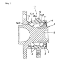
- a bearing device 11 includes: a bearing having an inner ring 12 with an inner ring track surface 12A on an outer peripheral surface, an outer ring 13 with an outer ring track surface 13A on an inner peripheral surface, and rolling elements 14, 14, ...
- a magnetic encoder 8 that is positioned at one axial end portion of the bearing and fixed to the inner ring 12; a magnetic sensor 10 that is fixed to the outer ring 13 and opposed to magnetic poles of the magnetic encoder 8 to detect rotation of the magnetic encoder 8; a cup-shaped protective cover 1 that is press-fitted into the outer ring 13 to cover the magnetic encoder 8 and intervene between the magnetic encoder 8 and the magnetic sensor 10; and a seal member 15 that is arranged at the other axial end portion of the bearing, and the like.
- the inside of the bearing is sealed by the protective cover 1 and the seal member 15 at the both axial end portions of the bearing, and the magnetic encoder 8 is accommodated in the inner space of the bearing. This allows the magnetic encoder 8 and the inside of the bearing to be protected from foreign matter or the like.
- the magnetic encoder 8 attached to the rotational inner ring 12 and having N and S poles alternately arranged at regular intervals in the circumferential direction and the magnetic sensor 10 attached to the fixed outer ring 13 constitute a rotation speed detector.
- a support member 9 is composed of a cylindrical part 9A and an annular part 9B extended radially outward from the end edge of the cylindrical part 9A.
- the magnetic encoder 8 having N and S poles alternately arranged at regular intervals in the circumferential direction is fixed to the annular part 9B.
- the magnetic encoder 8 When the cylindrical part 9A is externally fitted to the inner ring 12, the magnetic encoder 8 is fixed to the inner ring 12 via the support member 9 to rotate the magnetic encoder 8 integrally with the inner ring 12.
- the protective cover 1 As illustrated in the vertical cross-sectional view of Fig. 3(a) and the perspective view of Fig. 3(b) , the protective cover 1 according to the embodiment of the present invention includes: a first cylindrical part 2 press-fitted into the outer ring 13 (refer to Figs.
- a recess 6A is formed in the center of the disc part 6.
- the base part of the protective cover 1 (except for the seal body 7) is formed by performing press molding of an austenitic stainless steel plate material with a nickel content of 8.5 to 13 weight%.
- the seal body 7 is an elastic body such as synthetic rubber to improve airtightness between the protective cover 1 and the outer ring 13.
- the seal body 7 may be made from one of oil-resistant favorable rubber materials such as nitrile rubber (NBR), hydrogenated nitrile rubber (HNBR), acrylic rubber (ACM), ethylene-acrylic rubber (AEM), fluorine rubber (FKM, FPM), and silicone rubber (VQM), or a blend of two or more of the same.
- NBR nitrile rubber
- HNBR hydrogenated nitrile rubber
- ACM acrylic rubber
- AEM ethylene-acrylic rubber
- FKM fluorine rubber
- FPM fluorine rubber
- VQM silicone rubber
- the surface of the plate material for the base part of the protective cover 1 is dull-finished. This makes working oil likely to be retained at the press molding and prevents baking at the drawing process. Accordingly, scratches on the surface of the protective cover 1 are less prominent, and the matted surface improves the appearance of the protective cover 1 and the adhesion of the seal body 7.
- Table 1 shows the measured maximum values of residual flux densities of the austenitic stainless steel protective covers of the examples 1 to 3 and the comparative examples 1 and 2.
- Fig. 5 illustrates the relationship between the nickel contents and the residual flux densities in Table 1.
- Example/Comparative example Example 1 Example 2
- Example 3 Comparative Example 1 Comparative Example 2 Material (JIS steel grade) SUS304 SUS304L SUS316L SUS304 SUS304J2 Nickel content (weight%) 8.79 10.05 12.17 8.06 6.67 Residual flux density (mT) 0.11 0.04 0.03 0.20 0.21
- the austenitic stainless steel protective covers with relatively low nickel contents as the comparative examples 1 and 2 are larger in the measured maximum values of residual flux density, and the austenitic stainless steel protective covers with nickel contents of 8.5 weight% or more are smaller in the measured maximum values of residual flux density.
- the austenitic stainless steel protective covers with nickel contents of 10 weight% or more are significantly smaller in the measured maximum values of residual flux density.
- the austenitic stainless steel protective cover with a nickel content of 10.05 weight% in the example 2 has the measured maximum value of residual flux density of 0.04 mT
- the austenitic stainless steel protective cover with a nickel content of 8.06 weight% in the comparative example 1 has the measured maximum value of residual flux density of 0.20 mT.
- the example 2 with the higher nickel content has a significant smaller measured value of residual flux density that is 1/5 of that of the comparative example 1, and the example 2 is thus less magnetized.
- the content of nickel in an austenitic stainless steel plate material for cold press molding of a protective cover is more preferably 10 weight% or more from the viewpoint of making the protective cover less magnetized to satisfy required specifications for residual magnetic property, and is preferably 8.5 weight% or more from the viewpoint of making the protective cover less magnetized and suppressing the content of expensive nickel as much as possible.
- Nickel is an expensive material and therefore the upper limit of a nickel content is preferably 13 weight% or less from the viewpoint of suppressing a nickel content and reducing manufacturing costs.
- the material with a nickel content of 8.5 to 13 weight% may be preferably a SUS304 with a nickel content of 8.5 weight% or more as in the example 1, the SUS304L, the SUS316L, a JIS-based SUS305 with a nickel content of 10.50 to 13.00 weight% relative to the total weight, a SUS321 with a nickel content of 9.00 to 13.00 weight%, or a SUS347 with a nickel content of 9.00 to 13.00 weight%.
- the protective cover 1 according to the embodiment of the present invention as described above is formed by performing cold press molding of an austenitic stainless steel plate material with a nickel content of 8.5 to 13 weight%. Therefore, the material for the protective cover 1 (austenitic stainless steel) is significantly smaller in residual flux density than the SUS304 with a general nickel content (about 8 weight%).
- the protective cover 1 when being formed by cold press molding, the protective cover 1 is extremely less magnetized and is likely to satisfy required specifications for residual magnetic property.
- the protective cover 1 is not subjected to solution treatment, it is possible to prevent increase in manufacturing cost involved in the treatment and dimension changes due to heating, thereby improving the yield of the protective cover 1.
Landscapes
- Engineering & Computer Science (AREA)
- General Engineering & Computer Science (AREA)
- Mechanical Engineering (AREA)
- Physics & Mathematics (AREA)
- General Physics & Mathematics (AREA)
- Pressure Vessels And Lids Thereof (AREA)
- Sealing Of Bearings (AREA)
- Rolling Contact Bearings (AREA)
Abstract
Description
- The present invention relates to a cup-shaped protective cover that is press-fitted into an outer ring of a bearing to cover a magnetic encoder, and a bearing device including the protective cover.
- The antilock brake system (ABS) for use in efficient and safety braking without locking of wheels of automobiles was included in 45% of automobiles produced in Japan in 1996, and in more than 90% in 2009. At present, the antilock brake system is included in most of automobiles.
- The widespread antilock brake system is intended, for example, to detect the rotation speeds of wheels by a rotation speed detector (wheel speed sensor), calculate the acceleration and the deceleration and estimate the vehicle speed and the slip ratio by a controller, and drive an actuator to control the brake fluid pressure based on the calculation and estimation results.
- Bearing device with such a rotation speed detector in a roll bearing for supporting automobile wheels (hub bearing) is also widely used. There is a bearing device structured such that a seal member is fitted to the inner side of opposed surfaces of a rotational inner ring and a fixed outer ring, a magnetic encoder with N and S poles alternately arranged at regular intervals in the circumferential direction is attached to the inner ring at the inner side of the seal member, and a magnetic sensor is attached to the outer ring so as to be opposed to the magnetic encoder to detect the rotation of the magnetic encoder (for example, refer to Patent Document 1).
- In the structure of the bearing device as described in
Patent Document 1, muddy water or magnetized iron pieces may enter between the magnetic encoder and the magnetic sensor, which causes damage to the magnetic encoder and the magnetic sensor or changes in magnetic property of the magnetic encoder. In addition, the rotation torque of the bearing device increases due to sliding resistance of the seal member positioned at the outer side of the magnetic encoder. - To solve these problems, there is a bearing device in which a cup-shaped protective cover is press-fitted into the inner end portion of the outer ring to cover the magnetic encoder from the inner side without the seal member (for example, refer to Patent Document 2).
-
- Patent Document 1:
JP-A No.2005-241351 - Patent Document 2:
JP-A No.2011-084265 - According to
Patent Document 2, the magnetic force of the magnetic encoder needs to penetrate through the protective cover and reach the magnetic sensor, and thus the protective cover is to be non-magnetic and corrosion-resistive. Accordingly, the material for the protective cover is generally an austenitic stainless steel SUS304 containing chrome-nickel as a main component. The protective cover is generally formed by performing press molding of a SUS304 plate material. - The inventor of the subject application has produced a protective cover of a desired shape by performing cold press molding of a general-composition SUS304 plate material and has found that a large part of the plate material changed from austenite to martensite due to deformation-induced martensitic transformation.
- The martensite structure has the property of being magnetized. When the protective cover with a large part having undergone deformation-induced martensitic transformation is used, the protective cover may disturb a magnetic field between the magnetic encoder and the magnetic sensor to exert an adverse effect on detection accuracy.
- The part having undergone deformation-induced martensitic transformation can be returned to austenite by solution treatment (solution heat treatment). However, the execution of solution treatment leads to cost increase and may cause dimension changes due to heating.
- Accordingly, it is desired to use an austenitic stainless steel plate for the protective cover without any portion having undergone deformation-induced martensitic transformation or with a small portion having undergone deformation-induced martensitic transformation when the cup-shaped protective cover is formed by performing cold press molding of the material.
- In view of the foregoing circumstances, an object of the present invention is to provide a protective cover that is less magnetized and is likely to satisfy required specifications for residual magnetic property when the protective cover is formed by performing cold press molding of an austenitic stainless steel plate material.
- The inventor of the subject application has earnestly studied an austenitic stainless steel material including chrome nickel as a main component, taking notice of a nickel content relative to the total weight. Then, the inventor has tried to produce a cup-shaped protective cover sufficiently satisfying required specifications for residual magnetic property through cold press molding while suppressing the content of nickel as an expensive metal but making the content of nickel higher than the general content of nickel in a commercially supplied SUS304. Then, the inventor has evaluated and examined the residual magnetic property of the protective cover after the press molding, thereby completing the present invention.
- Specifically, to solve the foregoing problems, the protective cover according to the present invention is a cup-shaped protective cover for a bearing device including: an inner ring with an inner ring track surface on an outer peripheral surface; an outer ring with an outer ring track surface on an inner peripheral surface; a bearing with a rolling element between the inner ring track surface and the outer ring track surface; a magnetic encoder that is positioned at one axial end portion of the bearing, fixed to the inner ring, and has N and S poles alternately arranged at regular intervals in the circumferential direction; and a magnetic sensor that is fixed to the outer ring so as to be opposed to the magnetic poles of the magnetic encoder to detect the rotation of the magnetic encoder, wherein the protective cover is press-fitted into the outer ring to cover the magnetic encoder and intervene between the magnetic encoder and the magnetic sensor, and the protective cover is formed by performing cold press molding of an austenitic stainless steel plate material with a nickel content of 8.5 to 13 weight%.
- According to this configuration, the protective cover is formed by performing cold press molding of an austenitic stainless steel plate material with a nickel content of 8.5 to 13 weight%, and thus the residual flux density of nickel in the material (austenitic stainless steel) for the cold-pressed protective cover is significantly lower than that in the case of using a SUS304 with a general nickel content (about 8 weight%).
- Accordingly, the cold-pressed protective cover is hardly magnetized and is likely to satisfy the required specifications for residual magnetic property.
- In addition, since the protective cover is not subjected to solution treatment, it is possible to prevent increase in manufacturing costs and dimension changes due to heating to improve the yield of products.
- The bearing device according to the present invention includes the protective cover.
- According to the present invention, the protective cover and the bearing device including the protective cover produce significant advantages that the cold-pressed protective cover has a low residual flux density, and thus is hardly magnetized and is likely to satisfy the required specifications for residual magnetic property.
-
-
Fig. 1 is a vertical cross-sectional view of a bearing device with a protective cover according to an embodiment of the present invention; -
Fig. 2 is an enlarged vertical cross-sectional view of main parts of the same; -
Fig. 3(a) and (b) illustrate the protective cover according to the embodiment of the present invention:Fig. 3(a) is a vertical cross-sectional view; andFig. 3(b) is a perspective view; -
Fig. 4 is a front view of a configuration example of an experiment device that measures the residual flux density of a sensing surface of the protective cover; and -
Fig. 5 is a graph showing the relationship between the nickel contents and the residual flux densities in Table 1. - Embodiment of the present invention will be described below in detail with reference to the accompanying drawings. However, the present invention is not limited to the embodiment illustrated in the accompanying drawings but includes all of embodiments satisfying requirements described in the claims.
- As illustrated in the vertical cross-sectional view of
Fig. 1 and the enlarged vertical cross-sectional view of main parts ofFig. 2 , abearing device 11 according to the embodiment of the present invention includes: a bearing having aninner ring 12 with an innerring track surface 12A on an outer peripheral surface, anouter ring 13 with an outerring track surface 13A on an inner peripheral surface, androlling elements ring track surface 12A and the outerring track surface 13A; amagnetic encoder 8 that is positioned at one axial end portion of the bearing and fixed to theinner ring 12; amagnetic sensor 10 that is fixed to theouter ring 13 and opposed to magnetic poles of themagnetic encoder 8 to detect rotation of themagnetic encoder 8; a cup-shapedprotective cover 1 that is press-fitted into theouter ring 13 to cover themagnetic encoder 8 and intervene between themagnetic encoder 8 and themagnetic sensor 10; and aseal member 15 that is arranged at the other axial end portion of the bearing, and the like. - The inside of the bearing is sealed by the
protective cover 1 and theseal member 15 at the both axial end portions of the bearing, and themagnetic encoder 8 is accommodated in the inner space of the bearing. This allows themagnetic encoder 8 and the inside of the bearing to be protected from foreign matter or the like. - The
magnetic encoder 8 attached to the rotationalinner ring 12 and having N and S poles alternately arranged at regular intervals in the circumferential direction and themagnetic sensor 10 attached to the fixedouter ring 13 constitute a rotation speed detector. - A
support member 9 is composed of acylindrical part 9A and anannular part 9B extended radially outward from the end edge of thecylindrical part 9A. Themagnetic encoder 8 having N and S poles alternately arranged at regular intervals in the circumferential direction is fixed to theannular part 9B. - When the
cylindrical part 9A is externally fitted to theinner ring 12, themagnetic encoder 8 is fixed to theinner ring 12 via thesupport member 9 to rotate themagnetic encoder 8 integrally with theinner ring 12. - As illustrated in the vertical cross-sectional view of
Fig. 3(a) and the perspective view ofFig. 3(b) , theprotective cover 1 according to the embodiment of the present invention includes: a firstcylindrical part 2 press-fitted into the outer ring 13 (refer toFigs. 1 and2 ); a secondcylindrical part 3 smaller in diameter than the firstcylindrical part 2 and connected to an end edge of the firstcylindrical part 2; anannular part 4 connected to an end edge of the secondcylindrical part 3 and extended radially inward; a thirdcylindrical part 5 connected to an inner diameter-side end edge of thecylindrical part 4 and extended in the axial direction; adisc part 6 connected to an end edge of the thirdcylindrical part 5; and aseal body 7 vulcanized and adhered to the outer peripheral surface of the secondcylindrical part 3. Arecess 6A is formed in the center of thedisc part 6. - The base part of the protective cover 1 (except for the seal body 7) is formed by performing press molding of an austenitic stainless steel plate material with a nickel content of 8.5 to 13 weight%.
- The
seal body 7 is an elastic body such as synthetic rubber to improve airtightness between theprotective cover 1 and theouter ring 13. Theseal body 7 may be made from one of oil-resistant favorable rubber materials such as nitrile rubber (NBR), hydrogenated nitrile rubber (HNBR), acrylic rubber (ACM), ethylene-acrylic rubber (AEM), fluorine rubber (FKM, FPM), and silicone rubber (VQM), or a blend of two or more of the same. - Further, the surface of the plate material for the base part of the
protective cover 1 is dull-finished. This makes working oil likely to be retained at the press molding and prevents baking at the drawing process. Accordingly, scratches on the surface of theprotective cover 1 are less prominent, and the matted surface improves the appearance of theprotective cover 1 and the adhesion of theseal body 7. - Next, descriptions will be given as to experiments on the
protective cover 1 formed by performing cold press molding of a material with a higher nickel content than a general nickel content (about 8% of the total weight) of a commercially supplied SUS304 for evaluation of residual magnetic property. -
- (1) First, the
protective cover 1 formed by performing cold press molding of an austenitic stainless steel plate material was stored in a magnetization coil (air core coil with a diameter of 100 mm produced by Magnet Force Co., Ltd). A saturation magnetic field was applied to theprotective cover 1 by a magnetizing electric power supply (oil condenser-type magnetizing electric power supply MFC-1510 produced by Magnet Force Co., Ltd). - (2) Next, the
protective cover 1 with the saturation magnetic field was fixed on a turning table 16 in axial alignment with each other, as illustrated in the front view of a configuration example of an experiment device ofFig. 4 . A probe (axial probe MSA-410 produced by Toyo Corporation) supported by asupport instrument 17 was arranged so as to be axially opposed to the sensing surface of theprotective cover 1 with a gap of 0.5 mm therebetween in the height direction. A tesla meter (410-type handy gauss meter produced by Toyo Corporation) was used to measure the maximum value of the residual flux density of theprotective cover 1 while the turning table 16 was turned. - As examples 1 to 3, commercially supplied austenitic stainless steel plate materials of the following steel grades were selected:
- Of JIS-based SUS304 materials with a nickel content of 8.00 to 10.50% relative to the total weight, a SUS304 with a nickel content of 8.79% was used.
- Of JIS-based SUS304L materials with a nickel content of 9.00 to 13.00% relative to the total weight, a SUS304L with a nickel content of 10.05% was used.
- Of JIS-based SUS316L materials with a nickel content of 12.00 to 15.00% relative to the total weight, a SUS316L with a nickel content of 12.17% was used.
- As comparative examples 1 and 2, commercially supplied austenitic stainless steel plate materials of the following steel grades were selected:
- Of JIS-based SUS304 materials with a nickel content of 8.00 to 10.50% relative to the total weight, a SUS304 with a nickel content of 8.06% was used.
- Of JIS-based SUS304J2 materials with a nickel content of 6.00 to 9.00% relative to the total weight, a SUS304J2 with a nickel content of 6.67% was used.
- Table 1 shows the measured maximum values of residual flux densities of the austenitic stainless steel protective covers of the examples 1 to 3 and the comparative examples 1 and 2.
Fig. 5 illustrates the relationship between the nickel contents and the residual flux densities in Table 1.[Table 1] Example/Comparative example Example 1 Example 2 Example 3 Comparative Example 1 Comparative Example 2 Material (JIS steel grade) SUS304 SUS304L SUS316L SUS304 SUS304J2 Nickel content (weight%) 8.79 10.05 12.17 8.06 6.67 Residual flux density (mT) 0.11 0.04 0.03 0.20 0.21 - It is understood from
Fig. 5 that the austenitic stainless steel protective covers with relatively low nickel contents as the comparative examples 1 and 2 are larger in the measured maximum values of residual flux density, and the austenitic stainless steel protective covers with nickel contents of 8.5 weight% or more are smaller in the measured maximum values of residual flux density. In particular, it is noted that the austenitic stainless steel protective covers with nickel contents of 10 weight% or more are significantly smaller in the measured maximum values of residual flux density. - For example, the austenitic stainless steel protective cover with a nickel content of 10.05 weight% in the example 2 has the measured maximum value of residual flux density of 0.04 mT, and the austenitic stainless steel protective cover with a nickel content of 8.06 weight% in the comparative example 1 has the measured maximum value of residual flux density of 0.20 mT.
- Accordingly, it is understood that, as compared to the comparative example 1 with the lower nickel content, the example 2 with the higher nickel content has a significant smaller measured value of residual flux density that is 1/5 of that of the comparative example 1, and the example 2 is thus less magnetized.
- In addition, the same measurement was performed on a part other than the sensing surface (for example, the first
cylindrical part 2 illustrated inFig. 2 ), which revealed that the examples are significantly smaller in residual flux density than the comparative examples similar to the case of the sensing surface. - As described above, the content of nickel in an austenitic stainless steel plate material for cold press molding of a protective cover is more preferably 10 weight% or more from the viewpoint of making the protective cover less magnetized to satisfy required specifications for residual magnetic property, and is preferably 8.5 weight% or more from the viewpoint of making the protective cover less magnetized and suppressing the content of expensive nickel as much as possible.
- Nickel is an expensive material and therefore the upper limit of a nickel content is preferably 13 weight% or less from the viewpoint of suppressing a nickel content and reducing manufacturing costs.
- The material with a nickel content of 8.5 to 13 weight% may be preferably a SUS304 with a nickel content of 8.5 weight% or more as in the example 1, the SUS304L, the SUS316L, a JIS-based SUS305 with a nickel content of 10.50 to 13.00 weight% relative to the total weight, a SUS321 with a nickel content of 9.00 to 13.00 weight%, or a SUS347 with a nickel content of 9.00 to 13.00 weight%.
- The
protective cover 1 according to the embodiment of the present invention as described above is formed by performing cold press molding of an austenitic stainless steel plate material with a nickel content of 8.5 to 13 weight%. Therefore, the material for the protective cover 1 (austenitic stainless steel) is significantly smaller in residual flux density than the SUS304 with a general nickel content (about 8 weight%). - Accordingly, when being formed by cold press molding, the
protective cover 1 is extremely less magnetized and is likely to satisfy required specifications for residual magnetic property. - In addition, since the
protective cover 1 is not subjected to solution treatment, it is possible to prevent increase in manufacturing cost involved in the treatment and dimension changes due to heating, thereby improving the yield of theprotective cover 1. -
- 1
- Protective cover
- 2
- First cylindrical part
- 3
- Second cylindrical part
- 4
- Annular part
- 5
- Third cylindrical part
- 6
- Disc part
- 6A
- Recess
- 7
- Seal body
- 8
- Magnetic encoder
- 9
- Support member
- 9A
- Cylindrical part
- 9B
- Annular part
- 10
- Magnetic sensor
- 11
- Bearing device
- 12
- Inner ring
- 12A
- Inner ring track surface
- 13
- Outer ring
- 13A
- Outer ring track surface
- 14
- Rolling element
- 15
- Seal member
- 16
- Turning table
- 17
- Support instrument
- 18
- Probe
Claims (2)
- A cup-shaped protective cover for a bearing device including: an inner ring with an inner ring track surface on an outer peripheral surface; an outer ring with an outer ring track surface on an inner peripheral surface; a bearing with a rolling element between the inner ring track surface and the outer ring track surface; a magnetic encoder that is positioned at one axial end portion of the bearing, fixed to the inner ring, and has N and S poles alternately arranged at regular intervals in the circumferential direction; and a magnetic sensor that is fixed to the outer ring so as to be opposed to the magnetic poles of the magnetic encoder to detect the rotation of the magnetic encoder,
the protective cover being press-fitted into the outer ring to cover the magnetic encoder and intervene between the magnetic encoder and the magnetic sensor, wherein
the protective cover is formed by performing cold press molding of an austenitic stainless steel plate material with a nickel content of 8.5 to 13 weight%. - A bearing device comprising the protective cover according to claim 1.
Applications Claiming Priority (2)
| Application Number | Priority Date | Filing Date | Title |
|---|---|---|---|
| JP2014173807 | 2014-08-28 | ||
| JP2015114475A JP2016050674A (en) | 2014-08-28 | 2015-06-05 | Protection cover and bearing device with the same |
Publications (1)
| Publication Number | Publication Date |
|---|---|
| EP2990215A1 true EP2990215A1 (en) | 2016-03-02 |
Family
ID=54065181
Family Applications (1)
| Application Number | Title | Priority Date | Filing Date |
|---|---|---|---|
| EP15181742.6A Withdrawn EP2990215A1 (en) | 2014-08-28 | 2015-08-20 | Protective cover and bearing device including protective cover |
Country Status (4)
| Country | Link |
|---|---|
| US (2) | US20160059627A1 (en) |
| EP (1) | EP2990215A1 (en) |
| JP (1) | JP2016050674A (en) |
| CN (1) | CN105387085A (en) |
Families Citing this family (6)
| Publication number | Priority date | Publication date | Assignee | Title |
|---|---|---|---|---|
| JP6354402B2 (en) * | 2014-07-09 | 2018-07-11 | 中西金属工業株式会社 | Protective cover for bearing device, method for manufacturing the same, and method for manufacturing mechanical parts made of metal and rubber |
| JP6294394B2 (en) * | 2016-06-28 | 2018-03-14 | Ntn株式会社 | Wheel bearing device |
| JP6874431B2 (en) * | 2017-03-10 | 2021-05-19 | 中西金属工業株式会社 | Rotating seal |
| US11001099B2 (en) * | 2017-10-10 | 2021-05-11 | Aktiebolaget Skf | Wheel hub assembly having dual angular position sensors |
| DE102019212595A1 (en) * | 2018-09-07 | 2020-03-12 | Aktiebolaget Skf | Sealing device for a wheel bearing unit |
| US20240060536A1 (en) * | 2022-08-22 | 2024-02-22 | Schaeffler Technologies AG & Co. KG | Wheel bearing |
Citations (5)
| Publication number | Priority date | Publication date | Assignee | Title |
|---|---|---|---|---|
| JP2005241351A (en) | 2004-02-25 | 2005-09-08 | Ntn Corp | Bearing device with rotational speed detector |
| JP2007101443A (en) * | 2005-10-06 | 2007-04-19 | Nsk Ltd | Rolling bearing unit with magnetic encoder, and manufacturing method therefor |
| US20100027927A1 (en) * | 2006-11-16 | 2010-02-04 | Katsura Koyagi | Sensor attaching sealing device and vehicle rolling bearing using the same |
| JP2011084265A (en) | 2009-09-17 | 2011-04-28 | Ntn Corp | Bearing device for wheel |
| JP2012224265A (en) * | 2011-04-21 | 2012-11-15 | Ntn Corp | Bearing device for wheel |
Family Cites Families (12)
| Publication number | Priority date | Publication date | Assignee | Title |
|---|---|---|---|---|
| JPH02141556A (en) * | 1988-11-21 | 1990-05-30 | Nippon Kinzoku Kogyo Kk | Nonmagnetic stainless steel having excellent cold workability |
| JP2001330038A (en) * | 2000-03-17 | 2001-11-30 | Nsk Ltd | Rolling supporting device |
| CN100442041C (en) * | 2003-05-22 | 2008-12-10 | 日本精工株式会社 | Load measuring device for rolling bearing unit and load masuring rolling bearing unit |
| FR2919030B1 (en) * | 2007-07-20 | 2009-10-23 | Snr Roulements Sa | ASSEMBLY FORMING BEARING BEARING EQUIPPED WITH AN INFORMATION SENSOR SYSTEM |
| WO2011034134A1 (en) | 2009-09-17 | 2011-03-24 | Ntn株式会社 | Bearing device for a wheel, equipped with a rotational-speed measurement device |
| JP5592130B2 (en) * | 2010-03-18 | 2014-09-17 | Ntn株式会社 | Wheel bearing device with rotation speed detector |
| CN102481806B (en) * | 2010-07-22 | 2016-03-02 | 日本精工株式会社 | With the wheel-support rolling bearing unit of code device |
| EP2685117B1 (en) * | 2011-03-09 | 2019-12-25 | NTN Corporation | Wheel hub rolling bearing assembly with an encoder and a sealing cover for a vehicle wheel |
| JP5979775B2 (en) * | 2012-02-10 | 2016-08-31 | 内山工業株式会社 | Cap for bearing device |
| DE102012223881A1 (en) * | 2012-12-20 | 2014-06-26 | Schaeffler Technologies Gmbh & Co. Kg | Sensed wheel bearing unit |
| ITTO20130007A1 (en) * | 2013-01-08 | 2014-07-09 | Skf Ab | BEARING GROUP FOR A WHEEL OF A VEHICLE |
| JP6432125B2 (en) * | 2013-10-24 | 2018-12-05 | 中西金属工業株式会社 | Magnetic encoder and bearing device provided with magnetic encoder |
-
2015
- 2015-06-05 JP JP2015114475A patent/JP2016050674A/en active Pending
- 2015-08-20 EP EP15181742.6A patent/EP2990215A1/en not_active Withdrawn
- 2015-08-26 US US14/836,046 patent/US20160059627A1/en not_active Abandoned
- 2015-08-28 CN CN201510541056.2A patent/CN105387085A/en active Pending
-
2017
- 2017-08-02 US US15/666,660 patent/US10005318B2/en active Active
Patent Citations (5)
| Publication number | Priority date | Publication date | Assignee | Title |
|---|---|---|---|---|
| JP2005241351A (en) | 2004-02-25 | 2005-09-08 | Ntn Corp | Bearing device with rotational speed detector |
| JP2007101443A (en) * | 2005-10-06 | 2007-04-19 | Nsk Ltd | Rolling bearing unit with magnetic encoder, and manufacturing method therefor |
| US20100027927A1 (en) * | 2006-11-16 | 2010-02-04 | Katsura Koyagi | Sensor attaching sealing device and vehicle rolling bearing using the same |
| JP2011084265A (en) | 2009-09-17 | 2011-04-28 | Ntn Corp | Bearing device for wheel |
| JP2012224265A (en) * | 2011-04-21 | 2012-11-15 | Ntn Corp | Bearing device for wheel |
Non-Patent Citations (1)
| Title |
|---|
| LONGHAI ET AL: "JIS SUS304 Steel Physical Properties Characteristics for grade SUS304 Chemical composition % of the ladle analysis of grade SUS304 Mechanical properties of grade SUS304", 15 October 2012 (2012-10-15), pages 1 - 1, XP055243303, Retrieved from the Internet <URL:https://web.archive.org/web/20160120143853/http://www.steel-grades.com/pdf/files/austenitic-special-steel-JIS-SUS304.pdf> [retrieved on 20160120] * |
Also Published As
| Publication number | Publication date |
|---|---|
| US10005318B2 (en) | 2018-06-26 |
| JP2016050674A (en) | 2016-04-11 |
| US20160059627A1 (en) | 2016-03-03 |
| CN105387085A (en) | 2016-03-09 |
| US20170326914A1 (en) | 2017-11-16 |
Similar Documents
| Publication | Publication Date | Title |
|---|---|---|
| US10005318B2 (en) | Protective cover and bearing device including protective cover | |
| EP1810844B1 (en) | Rolling bearing system for vehicles | |
| JP5914585B2 (en) | Wheel bearing device | |
| US7255014B2 (en) | Wheel bearing apparatus incorporated with a wheel speed detecting apparatus | |
| US7618194B2 (en) | Wheel bearing apparatus incorporated with a wheel speed detecting apparatus | |
| CN207122497U (en) | Bearing apparatus for wheel | |
| JP4683496B2 (en) | Wheel bearing device | |
| WO2015137415A1 (en) | Wheel bearing device | |
| JP2004270872A (en) | Bearing for wheel | |
| WO2017051836A1 (en) | Bearing device for vehicle wheel | |
| US20190070900A1 (en) | Bearing device for vehicle wheel | |
| JP5666948B2 (en) | Wheel bearing device | |
| US8054064B2 (en) | Sensor holder with a wheel bearing apparatus incorporated with a wheel speed detecting apparatus including an annular fitting member in the sensor holder and a seal positioned between the annular fitting member and an outer circumference of an inner ring | |
| JP2014190464A (en) | Bearing device for wheel | |
| JP4375790B2 (en) | Wheel bearing device with rotation speed detector | |
| JP2007163397A (en) | Magnetized pulser ring | |
| JP2008002620A (en) | Sealing device with magnetic encoder and rolling bearing unit | |
| JP2008144950A (en) | Rotating speed detecting device, sealing device including the same, and wheel rolling bearing | |
| JP2015081657A (en) | Protective cover and bearing device including protective cover | |
| JP2004361259A (en) | Sensor device, and rolling bearing unit with sensor | |
| WO2015041354A1 (en) | Wheel bearing device | |
| JP2013047527A (en) | Sealing device of rolling bearing | |
| JP2007333182A (en) | Seal structure with encoder | |
| JP2002155962A (en) | Bearing for wheel | |
| JP2011107008A (en) | Magnetic encoder, and bearing device for wheel including the same |
Legal Events
| Date | Code | Title | Description |
|---|---|---|---|
| PUAI | Public reference made under article 153(3) epc to a published international application that has entered the european phase |
Free format text: ORIGINAL CODE: 0009012 |
|
| AK | Designated contracting states |
Kind code of ref document: A1 Designated state(s): AL AT BE BG CH CY CZ DE DK EE ES FI FR GB GR HR HU IE IS IT LI LT LU LV MC MK MT NL NO PL PT RO RS SE SI SK SM TR |
|
| AX | Request for extension of the european patent |
Extension state: BA ME |
|
| 17P | Request for examination filed |
Effective date: 20160714 |
|
| RBV | Designated contracting states (corrected) |
Designated state(s): AL AT BE BG CH CY CZ DE DK EE ES FI FR GB GR HR HU IE IS IT LI LT LU LV MC MK MT NL NO PL PT RO RS SE SI SK SM TR |
|
| 17Q | First examination report despatched |
Effective date: 20200612 |
|
| STAA | Information on the status of an ep patent application or granted ep patent |
Free format text: STATUS: THE APPLICATION HAS BEEN WITHDRAWN |
|
| 18W | Application withdrawn |
Effective date: 20200810 |