EP2990076A1 - Implantat mit einer mri-geräteerkennung - Google Patents
Implantat mit einer mri-geräteerkennung Download PDFInfo
- Publication number
- EP2990076A1 EP2990076A1 EP15173598.2A EP15173598A EP2990076A1 EP 2990076 A1 EP2990076 A1 EP 2990076A1 EP 15173598 A EP15173598 A EP 15173598A EP 2990076 A1 EP2990076 A1 EP 2990076A1
- Authority
- EP
- European Patent Office
- Prior art keywords
- light
- led
- faraday element
- tesla
- imd according
- Prior art date
- Legal status (The legal status is an assumption and is not a legal conclusion. Google has not performed a legal analysis and makes no representation as to the accuracy of the status listed.)
- Granted
Links
Images

Classifications
-
- G—PHYSICS
- G01—MEASURING; TESTING
- G01R—MEASURING ELECTRIC VARIABLES; MEASURING MAGNETIC VARIABLES
- G01R33/00—Arrangements or instruments for measuring magnetic variables
- G01R33/02—Measuring direction or magnitude of magnetic fields or magnetic flux
- G01R33/032—Measuring direction or magnitude of magnetic fields or magnetic flux using magneto-optic devices, e.g. Faraday or Cotton-Mouton effect
- G01R33/0322—Measuring direction or magnitude of magnetic fields or magnetic flux using magneto-optic devices, e.g. Faraday or Cotton-Mouton effect using the Faraday or Voigt effect
-
- A—HUMAN NECESSITIES
- A61—MEDICAL OR VETERINARY SCIENCE; HYGIENE
- A61B—DIAGNOSIS; SURGERY; IDENTIFICATION
- A61B5/00—Measuring for diagnostic purposes; Identification of persons
- A61B5/0002—Remote monitoring of patients using telemetry, e.g. transmission of vital signals via a communication network
- A61B5/0031—Implanted circuitry
-
- A—HUMAN NECESSITIES
- A61—MEDICAL OR VETERINARY SCIENCE; HYGIENE
- A61N—ELECTROTHERAPY; MAGNETOTHERAPY; RADIATION THERAPY; ULTRASOUND THERAPY
- A61N1/00—Electrotherapy; Circuits therefor
- A61N1/18—Applying electric currents by contact electrodes
- A61N1/32—Applying electric currents by contact electrodes alternating or intermittent currents
- A61N1/36—Applying electric currents by contact electrodes alternating or intermittent currents for stimulation
- A61N1/362—Heart stimulators
- A61N1/37—Monitoring; Protecting
- A61N1/3718—Monitoring of or protection against external electromagnetic fields or currents
-
- A—HUMAN NECESSITIES
- A61—MEDICAL OR VETERINARY SCIENCE; HYGIENE
- A61B—DIAGNOSIS; SURGERY; IDENTIFICATION
- A61B90/00—Instruments, implements or accessories specially adapted for surgery or diagnosis and not covered by any of the groups A61B1/00 - A61B50/00, e.g. for luxation treatment or for protecting wound edges
- A61B90/39—Markers, e.g. radio-opaque or breast lesions markers
- A61B2090/3937—Visible markers
- A61B2090/3945—Active visible markers, e.g. light emitting diodes
-
- G—PHYSICS
- G01—MEASURING; TESTING
- G01R—MEASURING ELECTRIC VARIABLES; MEASURING MAGNETIC VARIABLES
- G01R33/00—Arrangements or instruments for measuring magnetic variables
- G01R33/20—Arrangements or instruments for measuring magnetic variables involving magnetic resonance
- G01R33/28—Details of apparatus provided for in groups G01R33/44 - G01R33/64
- G01R33/285—Invasive instruments, e.g. catheters or biopsy needles, specially adapted for tracking, guiding or visualization by NMR
-
- G—PHYSICS
- G01—MEASURING; TESTING
- G01R—MEASURING ELECTRIC VARIABLES; MEASURING MAGNETIC VARIABLES
- G01R33/00—Arrangements or instruments for measuring magnetic variables
- G01R33/20—Arrangements or instruments for measuring magnetic variables involving magnetic resonance
- G01R33/28—Details of apparatus provided for in groups G01R33/44 - G01R33/64
- G01R33/288—Provisions within MR facilities for enhancing safety during MR, e.g. reduction of the specific absorption rate [SAR], detection of ferromagnetic objects in the scanner room
Definitions
- the disclosed technology relates to an implant with a magnetic field detection, in particular to an implant for detection of fields generated by an MRI device.
- MRI Magnetic Resonance Imaging
- IMD implanted medical device
- the US 2011/0152672 A1 describes an implant in which an electro-optical transducer is used to detect RFI / RF fields typical of MRI devices.
- the US 6,462,539 B2 relates to an apparatus for determining magnetic fields by means of an optical structure with a birefringence element based on the Faraday effect.
- the prior art described relates in each case to a measurement of a static magnetic field or the measurement of typical RF / RF fields (hereinafter HF is also subsumed under RF) or a combination of two measurement methods for determining both the static magnetic fields and the RF fields.
- HF typically RF / RF fields
- a simultaneous detection of the RF / RF fields and the magnetic fields in a measuring device is not yet known.
- the existing optical structures for quantitative statements must be calibrated consuming or require a complex structure.
- the Faraday element can for this purpose be inserted into a molded part and / or connected to it and / or surrounded in a predetermined form by a material forming a solid material, for example cast.
- the bending ensures that the Faraday element is sensitive to magnetic fields in one plane and thus can detect the static magnetic field of an MRI device.
- a determination of the magnetic field takes place only in the plane spanned by the Faraday element.
- the light detected by the light detector can be evaluated by an evaluation unit and generate a corresponding control signal, which causes a changeover or maintenance of an operating mode of the implanted medical device.
- the described RF field that couples or acts in the communication coil is preferably an RF field, and more preferably an RF signal of an MRI device, wherein the frequency of the RF signal is dependent on the magnetic flux density of the MRI device.
- the angle can also have a different angle in adaptation to the implantable medical implant, in particular an angle adapted to the housing shape.
- the radius of curvature can also be adapted to the radius of curvature of the housing of the implantable medical device.
- only one Angle 90 ° or more but not all angles are 90 °.
- the at least two bends are designed so that the Faraday element has a longitudinal extension in all three spatial directions, so that a magnetic field determination is possible not only in one plane, but in the whole spanned by the three spatial directions tripod (space).
- implants are usually slightly expanded in one spatial direction, ie they are flat, it may be preferable to run a plurality of subsections in this direction, for example, to lay the Faraday element in zigzag or meandering in this spatial direction, by a sufficient distance for the detectable occurrence to provide the Faraday effect.
- the optical structure is integrated in a mounting frame, so that the molded part is wholly or partially part of a mounting frame.
- the molded part can also be wholly or partially inserted into the mounting frame and thus become part of the mounting frame.
- the polarization filters are adjusted so that no light exits through the second polarization filter without an applied magnetic field and no light falls on the light detector.
- the polarization filters are set as crossed. It is taken into account that the optical elements used can have an influence on the polarization direction of the light even without the presence of a magnetic field. This influence must be compensated during construction. Therefore, the angle between the polarization directions of the polarizing filters may deviate from 90 degrees. The angle can vary from one construction to the next; the important feature is that no or only a minimum amount of light emerges from the second polarization filter, so that the polarization filters are crossed if no magnetic field acts on the structure.
- the molded part is made of an opaque material and the molded part encloses the Faraday element so that light can enter the Faraday element only through the two sides connected to the polarization filters.
- This construction reduces stray light, which leads to increased background noise. This increases the sensitivity and accuracy of the magnetic field determination.
- the entire optical structure is encapsulated with an opaque plastic such that no stray light can couple into the optical structure. As with the molded article of an opaque material, stray light in the optical structure is minimized. Both measures for reducing the scattered light can also be combined.
- the Faraday element has a Verdetkonstante of at least 2 rads per (Tesla and meter) in the range of the light emitted by the LED spectrum or a portion of the emitted light spectrum.
- the Faraday element consists of a glass fiber.
- the Faraday element can also be formed from an annealed, that is to say a glass fiber which is stored at elevated temperature and slowly cooled.
- the annealing process can be carried out when the glass fiber has already been brought in the later intended form, in particular with respect to the bend or the bends.
- the Faraday element has at least one further bend, so that the Faraday element can detect a magnetic field in all three spatial directions.
- the execution of the then at least three Faraday element is an orthogonal tripod. Since in conventional implantable medical devices, a spatial extent is usually much shorter than in the other two, so analogous to a flat cuboid, it makes sense to return the Faraday element in this shorter spatial direction at least once, or even several times back and forth, so that the total length in this shorter spatial direction corresponds approximately to the length in the other spatial directions.
- the light detector is connected to an evaluation unit which determines from the change in intensity of the detected light whether the applied magnetic field has a magnetic flux density of less than or equal to 1 Tesla, or 1.5 Tesla or 3 Tesla or 7 Tesla.
- the evaluation unit generates a control signal as a function of the specific magnetic field strength or the magnetic flux density.
- the implanted medical device with the evaluation unit is able to draw different conclusions from the respectively detected light. For example, different modes of operation for the implanted medical device may be initiated by different detection results.
- a further embodiment is characterized in that a further optical path leads from the LED to the light detector or a further light detector, wherein the further optical path is designed so that it can be used as a reference without being influenced by a magnetic field.
- This further optical path can be realized for example by a light guide with a very low Verdetkonstanten in the range of the light emitted by the LED spectrum or part of the emitted light spectrum.
- the further optical path leads to a further light detector and that the light detectors are connected to an evaluation unit which determines from the change in intensity of the detected light whether the applied magnetic field has a magnetic flux density of less than or equal to 1 Tesla, or 1, 5 Tesla or 3 Tesla or 7 Tesla.
- the evaluation unit uses the further optical path as a reference path for determining the magnetic field strength or the magnetic flux density.
- the LED is additionally connected to the voltage source or another voltage source, ie biased, is that a lower RF coupling than without the connection to the voltage source or the other voltage source is already sufficient that the LED emits light. This makes the system more sensitive to the RF fields. It also increases the light output and thus reduces the measurement inaccuracy.
- the LED is protected by a current limiting.
- this achieves a limitation of the maximum light intensity, whereby a calibration of the system for determining the magnetic field strength or the magnetic flux density is possible.
- the RF fields induced in the communication coil are also evaluated and included in the magnetic field determination by the evaluation unit.
- the term magnetic field determination consistently refers to the magnetic flux density in Tesla, as this is the common indication in MRI devices.
- the bias voltage at the LED is just below the opening limit of the LED.
- the LED is decoupled from at least one capacitor on at least one side of DC components.
- FIG. 1 schematically shows the operation of a Faraday element, where P is the original polarization direction, B is the direction of the magnetic field, 1 is the length of the Faraday element, P 'is the resulting polarization direction, a and b are the major and minor semiaxes of the resulting ellipsoid, and theta F the Faraday rotation or the rotation angle of the polarization is and Eta F is the Faraday ellipticity.
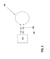
- FIG. 2 shows a part of the diagram of an implant with a voltage source, a control unit 110 and a communication coil 120, with at least one LED, preferably with two LEDs 130, 140 is connected to the communication coil electrical so that the at least one LED emits light when coupled via the communication coil typical for MRI devices RF field.
- the control unit 110 connects the communication coil to other components of the implantable medical implant.
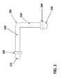
- the FIG. 3 schematically shows the optical structure.
- the LED 210 is connected via an optical structure to a light detector 250, for example a photodiode.
- Further components of the optical structure are a polarization filter 220, following at least one Faraday element 230 ', 230 ", eg doped glass rod with high Verdetkonstante or preferably a glass fiber with high Verdetkonstante, more preferably a polarization under polarization obtained glass fiber with a high Verdetkonstante, for example a
- the Farady element 230 ', 230 " is followed by another polarization filter 240, which is rotated by 90 ° to the first, ie crossed.
- the light detector 250 is connected to the control unit 110 or an evaluation unit (not shown) and may be connected by the control unit or the evaluation unit or directly to the voltage source or another voltage source.
- the light detector 250 sends a signal to the control unit 110 when it detects light above a predeterminable intensity.
- the signal may be a constant signal or may depend on the detected intensity.
- an evaluation unit can also read out a voltage and / or current signal from the light detector 250 and process it further or transmit it to the control unit 110.
- this housing can be completely or partially integrated in a mounting frame or be part or all of such a mounting frame.
- the elements of the optical structure can be fixed in one component and immovable against each other.
- the components of the optical structure can be cast in a plastic or be encapsulated with a plastic.
- FIG. 3 also shows an example of a Faraday element 230 ', 230 "having a bend 260 of 90 °.
- the Faraday element 230', 230" is divided into two regions 230 'and 230 ", each for a different component of the magnetic field in FIG
- the magnetic field can be detected independently of its position in the plane thus spanned by the two Faraday element sections.
- the plane spanned by the two Faraday elements 230 ', 230 " is preferably parallel to the housing side of the implant, which has the largest area.
- the two Faraday element sections 230 ', 230 can be realized by a glass fiber having a bend 260.
- the polarization filters are rotated relative to one another such that no light can pass the second polarization filter 240 without an applied magnetic field.
- the light of the at least one LED 130, 140, 210 can also be conducted on a further optical path without a Faraday element to a further light detector and thus be available as a reference.
- the reference can be used to deduce the quantitative rotation of the polarization and thus the strength of the magnetic field.
- the information about the magnetic field strength can be used to differentiate between different MRI device types (1 Tesla, 1.5 Tesla, 3 Tesla, 7 Tesla).
Landscapes
- Health & Medical Sciences (AREA)
- Engineering & Computer Science (AREA)
- Physics & Mathematics (AREA)
- Life Sciences & Earth Sciences (AREA)
- Power Engineering (AREA)
- Animal Behavior & Ethology (AREA)
- Veterinary Medicine (AREA)
- Biomedical Technology (AREA)
- Heart & Thoracic Surgery (AREA)
- Public Health (AREA)
- General Health & Medical Sciences (AREA)
- Nuclear Medicine, Radiotherapy & Molecular Imaging (AREA)
- Radiology & Medical Imaging (AREA)
- General Physics & Mathematics (AREA)
- Condensed Matter Physics & Semiconductors (AREA)
- Cardiology (AREA)
- Electromagnetism (AREA)
- Pathology (AREA)
- Biophysics (AREA)
- Surgery (AREA)
- Medical Informatics (AREA)
- Molecular Biology (AREA)
- Computer Networks & Wireless Communication (AREA)
- Measuring Magnetic Variables (AREA)
- High Energy & Nuclear Physics (AREA)
- Neurology (AREA)
Abstract
Description
- Die offenbarte Technologie bezieht sich auf ein Implantat mit einer Magnetfelderkennung, insbesondere auf ein Implantat zur Erkennung von Feldern, die durch ein MRI-Gerät erzeugt werden.
- Obwohl Untersuchungen mit MRI- (Magnetic Resonance Imaging, Kernspintomographie) Geräten einen immer höheren Stellenwert in der diagnostischen Medizin einnehmen, sind für einen nicht unerheblichen Teil der potentiellen Patienten die Untersuchungen mit MRI-Geräten kontraindiziert. Eine solche Kontraindikation kann zum Beispiel durch das Vorhandensein eines implantieren medizinischen Gerätes (IMD) gegeben sein.
- Es existieren verschiedene Ansätze, um die Kompatibilität von implantierten medizinischen Geräten mit MRI-Geräten, genauer mit den Arbeitsbedingungen im Einflussbereich eines MRI-Gerätes, zu erhöhen. So wird versucht die für MRI-Geräte charakteristischen Felder zu detektieren, um daraus entsprechende Konsequenzen ziehen zu können.
- Aus dem Stand der Technik sind verschiedene Methoden zur Detektion von Magnetfeldern und anderen elektromagnetischen Feldern bekannt.
So beschreibt dieUS 2008/0154342 A1 ein Magnetfelddetektor auf Basis eines GMR (Giant Magneto Resitence) Sensors oder eines Bandpassfilters in der Antennenschaltung. - Die
US 2011/0152672 A1 beschreibt ein Implantat, bei dem ein elektrooptischer Wandler zur Detektion von für MRI-Geräte typische RF-/HF-Felder verwendet wird. - Die
US 6,462,539 B2 bezieht sich auf eine Vorrichtung zum Bestimmen von Magnetfeldern mittels eines optischen Aufbaus mit einem Doppelbrechungselement, das auf dem Faradayeffekt beruht. - Der beschriebene Stand der Technik bezieht sich jeweils auf eine Messung eines statischen Magnetfeldes oder die Messung von typischen RF-/HF-Feldern (im Folgenden wird unter HF auch RF subsumiert) oder eine Kombination von zwei Messmethoden zur Bestimmung sowohl der statischen Magnetfelder als auch der HF-Felder. Eine gleichzeitige Detektion der RF-/HF-Felder und der Magnetfelder in einer Messeinrichtung ist bisher nicht bekannt. Auch die müssen die bisherigen optischen aufbauten für quantitative Aussagen aufwendig kalibriert werden oder bedürfen eines komplexen Aufbaus.
- Es ist Aufgabe der Erfindung, ein Messsystem für ein Implantat bereitzustellen, das diese Mängel im Stand der Technik behebt.
- Gelöst wird die Aufgabe durch ein Gerät nach dem unabhängigen Anspruch 1, ein implantierbares medizinisches Gerät (IMD) mit
- mindestens einer Spannungsquelle,
- mindestens einer Kontrolleinheit (110),
- mindestens einer Kommunikationsspule (120), und
- einem optischen Aufbau mit
- mindestens einer Leuchtdiode (LED) (130, 140, 210),
- mindestens einem Lichtdetektor (250),
- mindestens einem ersten und einem zweiten Polarisationsfilter (220, 240),
- mindestens einem Lichtleiter, der als Faradayelement (230', 230") ausgeführt ist, und wobei der optische Aufbau mindestens einen optischen Pfad enthält und wobei
- die mindestens eine LED (130, 140, 210) mit der Kommunikationsspule derart elektronisch verbunden ist, dass die LED (130, 140, 210) Licht emittiert, wenn in die Kommunikationsspule ein HF-Feld eingekoppelt,
- die LED (130, 140, 210) mit einer ersten Seite des ersten Polarisationsfilters (220) verbunden ist,
- eine zweite Seite des ersten Polarisationsfilters (220) mit einem ersten Ende des Faradayelements (230', 230") verbunden ist,
- eine erste Seite des zweiten Polarisationsfilters (240) mit einem zweiten Ende des Faradayelements (230', 230") verbunden ist,
- eine zweite Seite des zweiten Polarisationsfilters (240) mit dem Lichtdetektor (250) verbunden ist,
- das Faradayelement (230', 230") mindestens eine Biegung (260) aufweist und das Faradayelement (230', 230") durch die Biegung in mindestens zwei Abschnitte geteilt ist, und das Faradayelement (230', 230") in einem Formteil mit einer der Biegung (260) des Faradayelementes (230', 230") entsprechenden Biegung fest verankert ist.
- Das Faradayelement kann dafür in ein Formteil eingelegt und/oder mit diesem verbunden werden und/oder in einer vorgegebenen Form von einem einen Feststoff bildenden Material umgeben, zum Beispiel umgossen, werden. Durch die Biegung wird erreicht, dass das Faradayelement auf Magnetfelder in einer Ebene empfindlich ist und so das statische Magnetfeld eines MRI-Gerätes erfassen kann. Eine Bestimmung des Magnetfeldes erfolgt nur in der durch das Faradayelement aufgespannten Ebene.
Das von dem Lichtdetektor detektierte Licht kann von einer Auswerteeinheit ausgewertet werden und ein entsprechendes Steuersignal generieren, das eine Umschaltung oder Beibehaltung eines Betriebsmodus des implantierten medizinischen Gerätes bewirkt. Das Beschriebene HF-Feld, das in die Kommunikationsspule einkoppelt oder einwirkt, ist vorzugsweise ein RF-Feld und besonders bevorzug ein RF-Signal eines MRI-Gerätes, wobei die Frequenz des RF-Signals von der magnetischen Flussdichte des MRI-Gerätes abhängig ist. - Bevorzugt weist die mindestens eine Biegung zwischen den mindestens zwei Abschnitten des Faradayelementes einen Winkel von jeweils 90° auf. Der Winkel kann aber auch in Anpassung an das implantierbare medizinische Implantat einen anderen Winkel aufweisen, insbesondere einen an die Gehäuseform angepassten Winkel. Auch der Krümmungsradius kann an den Krümmungsradius des Gehäuses des implantierbaren medizinischen Gerätes angepasst sein. Alternativ können beim Vorhandensein von mehr als einer Biegung nur ein Winkel 90° betragen oder mehrere aber nicht alle Winkel 90° betragen. Besonders bevorzugt wird, dass die mindestens zwei Biegungen so gestaltet sind, dass das Faradayelement eine Längsausdehnung in allen drei Raumrichtungen hat, so dass eine Magnetfeldbestimmung nicht nur in einer Ebene, sondern im ganzen durch die drei Raumrichtungen aufgespannten Dreibein (Raum) möglich ist. Da Implantate in einer Raumrichtung meist wenig ausgedehnt sind, also flach sind, kann es bevorzugt sein, mehrere Teilabschnitte in dieser Richtung verlaufen zu lassen, also beispielsweise das Faradayelement im Zickzack oder mäandernd in dieser Raumrichtung zu verlegen, um eine ausreichende Strecke für das detektierbare Auftreten des Faradayeffektes bereitzustellen.
- Auch wird bevorzugt, dass der optische Aufbau in einen Montagerahmen integriert ist, das Formteil also ganz oder teilweise Bestandteil eines Montagerahmens ist. Das Formteil kann aber auch ganz oder teilweise in den Montagerahmen einfügt und so Bestandteil des Montagerahmens werden.
- In einer bevorzugten Ausführungsform sind die Polarisationsfilter so eingestellt, dass ohne ein anliegendes Magnetfeld kein Licht durch den zweiten Polarisationsfilter austritt und kein Licht auf den Lichtdetektor fällt. Die Polarisationsfilter sind als gekreuzt eingestellt. Dabei wird berücksichtigt, dass die verwendeten optischen Elemente auch ohne das Vorhandensein eines Magnetfeldes einen Einfluss auf die Polarisationsrichtung des Lichtes haben können. Dieser Einfluss muss beim Aufbau kompensiert werden. Daher kann der Winkel zwischen den Polarisationsrichtungen von den Polarisationsfiltern von 90° Grad abweichen. Der Winkel kann von Aufbau zu Aufbau variieren, wichtig ist die Eigenschaft, dass kein oder nur eine Mindestmaß an Licht aus dem zweiten Polarisationsfilter austritt, die Polarisationsfilter also gekreuzt stehen, wenn kein Magnetfeld auf den Aufbau wirkt.
- In einer weiteren Ausführungsform ist das Formteil aus einem lichtundurchlässigen Material und das Formteil umschließt das Faradayelement so, dass nur durch die beiden mit den Polarisationsfiltern verbundenen Seiten Licht in das Faradayelement eintreten kann. Dieser Aufbau reduziert Streulicht, das zu einem erhöhten Hintergrundrauschen führt. Damit wird die Empfindlichkeit und Genauigkeit der Magnetfeldbestimmung erhöht. Auch wird bevorzugt, dass der gesamte optische Aufbau mit einem lichtundurchlässigen Kunststoff derart umgossen wird, dass kein Streulicht in den optischen Aufbau einkoppeln kann. Wie bei dem Formteil aus einem lichtundurchlässigen Material wird Streulicht in dem optischen Aufbau minimiert. Beide Maßnahmen zur Streulichtreduzierung können auch kombiniert werden.
- In einer besonderen Ausführungsform weist das Faradayelement eine Verdetkonstante von mindestens 2 rad pro (Tesla und Meter) im Bereich des von der LED emittierten Lichtspektrums oder eines Teils des emittierten Lichtspektrums auf.
- Auch wird bevorzugt, dass das Faradayelement aus einer Glasfaser besteht. Insbesondere kann das Faradayelement auch aus einer getemperten, also einer bei erhöhter Temperatur gelagerten und langsam abgekühlten, Glasfaser gebildet werden. Insbesondere kann der Tempervorgang vorgenommen werden, wenn die Glasfaser bereits in der später angestrebten Form, vor allem in Bezug auf die Biegung oder die Biegungen, gebracht wurde.
- In einer bevorzugten Ausführungsform weist das Faradayelement mindestens eine weitere Biegung auf, so dass das Faradayelement in allen drei Raumrichtungen ein Magnetfeld detektieren kann. Besonders bevorzugt wird dabei die Ausführung der dann mindestens drei Faradayelement als ein orthogonales Dreibein. Da bei herkömmlichen implantierbaren medizinischen Geräten eine Raumausdehnung in der Regel deutlich kürzer ist als in die anderen beiden, also analog zu einem flachen Quader, ist es sinnvoll, das Faradayelement in dieser kürzeren Raumrichtung mindestens einmal, oder aber auch mehrmals hin und her zurückzuführen, so dass die Gesamtlänge in dieser kürzeren Raumrichtung in etwa der Länge in die anderen Raumrichtungen entspricht.
- Auch wird bevorzugt, dass der Lichtdetektor mit einer Auswerteeinheit verbunden ist, die anhand der Intensitätsänderung des detektierten Lichtes bestimmt, ob das anliegende Magnetfeld eine magnetische Flussdichte kleiner oder gleich 1 Tesla aufweist, oder 1,5 Tesla oder 3 Tesla oder 7 Tesla aufweist.
- Besonders bevorzugt wird, dass die Auswerteeinheit in Abhängigkeit von der bestimmten Magnetfeldstärke bzw. der magnetischen Flussdichte ein Steuersignal generiert. Dadurch ist das implantierte medizinische Gerät mit der Auswerteeinheit in der Lage, unterschiedliche Schlüsse aus dem jeweils detektierten Licht zu ziehen. So können beispielsweise unterschiedliche Betriebsmodi für das implantierte medizinische Gerät durch unterschiedliche Detektionsergebnisse initiiert werden.
- Eine weitere Ausführungsform zeichnet sich dadurch aus, dass ein weiterer optischer Pfad von der LED zu dem Lichtdetektor oder einen weiteren Lichtdetektor führt, wobei der weitere optische Pfad so ausgelegt wird, dass er als Referenz verwendet werden kann, ohne von einem Magnetfeld beeinflusst zu werden. Dieser weitere optische Pfad kann beispielsweise durch einen Lichtleiter mit einer sehr geringen Verdetkonstanten im Bereich des von der LED emittierten Lichtspektrums oder eines Teils des emittierten Lichtspektrums realisiert werden.
- Besonders bevorzugt wird , dass der weitere optische Pfad zu einem weiteren Lichtdetektor führt und das die Lichtdetektoren mit einer Auswerteeinheit verbunden sind, die anhand der Intensitätsänderung des detektierten Lichtes bestimmt, ob das anliegende Magnetfeld eine magnetische Flussdichte kleiner oder gleich 1 Tesla aufweist, oder 1,5 Tesla oder 3 Tesla oder 7 Tesla aufweist. Dabei verwendet die Auswerteeinheit den weiteren optischen Pfad als Referenzpfad zur Bestimmung der Magnetfeldstärke bzw. der magnetischen Flussdichte.
- In einer bevorzugten Ausführungsform ist die LED zusätzlich mit der Spannungsquelle oder einer weiteren Spannungsquelle derart verbunden, also vorgespannt, ist, dass eine geringere HF-Einkopplung als ohne die Verbindung mit der Spannungsquelle oder der weiteren Spannungsquelle bereits ausreicht, dass die LED Licht emittiert. Dadurch wird das System sensitiver für die HF-Felder. Auch wird dadurch die Lichtausbeute erhöht und damit die Messungenauigkeit reduziert.
- Bevorzugt wird auch, dass die LED durch eine Strombegrenzung geschützt wird. Zusätzlich erreicht man dadurch eine Begrenzung der maximalen Lichtintensität, wodurch eine Kalibrierung des Systems zur Bestimmung der Magnetfeldstärke bzw. der magnetischen Flussdichte möglich ist. Insbesondere ist dies möglich, wenn die in die Kommunikationsspule induzierten HF-Felder ebenfalls ausgewertet und von der Auswerteeinheit in die Magnetfeldbestimmung einbezogen werden. Der Begriff Magnetfeldbestimmung bezieht sich durchgehend auf die magnetische Flussdichte in Tesla, da dies die verbreitete Angabe bei MRI-Geräten ist.
- Auch wird bevorzugt, dass die Vorspannung an der LED knapp unterhalb der Öffnungsgrenze der LED liegt.
- In einer weiteren Ausführungsform ist die LED durch mindestens einen Kondensator an mindestens einer Seite von Gleichstromanteilen abgekoppelt.
- Im Folgenden wird die Erfindung an Hand von Figuren beschrieben.
- Fig. 1
- zeigt schematisch den Faraday-Effekt,
- Fig. 2
- zeigt die Kommunikationsspule mit zwei Leuchtdioden und einer Kontrolleinheit,
- Fig. 3
- zeigt einen erfindungsgemäßen optischen Aufbau mit einer Biegung.
- Die
Figur 1 zeigt schematisch die Funktionsweise eines Faradayelements, wobei P die ursprüngliche Polarisationsrichtung ist, B die Richtung des Magnetfeldes zeigt, 1 die Länge des Faradayelementes ist, P' die resultierende Polarisationsrichtung ist, a und b die große und kleine Halbachse des resultierenden Ellipsoiden sind und Theta F die Faraday-Rotation oder der Drehwinkel der Polarisation ist und Eta F die Faraday Ellipsität ist. - Die
Figur 2 zeigt einen Teil des Schaltbild eines Implantats mit einer Spannungsquelle, einer Kontrolleinheit 110 und einer Kommunikationsspule 120, die mit mindestens einer LED, bevorzugt mit zwei LEDs 130, 140 mit der Kommunikationsspule elektrische so verbunden ist, dass die mindestens eine LED Licht emittiert, wenn über die Kommunikationsspule ein für MRI-Geräte typisches HF-Feld eingekoppelt wird. Die Kontrolleinheit 110 verbindet die Kommunikationsspule mit anderen Komponenten des implantierbaren medizinischen Implantats. - Die
Figur 3 zeigt schematisch den optischen Aufbau. Die LED 210 ist über einen optischen Aufbau mit einem Lichtdetektor 250, z.B. einer Photodiode, verbunden. Weitere Bestandteile des optischen Aufbaus sind ein Polarisationsfilter 220, darauf folgend mindestens ein Faradayelement 230', 230", z.B. dotierter Glasstab mit hoher Verdetkonstante oder bevorzugt eine Glasfaser mit hoher Verdetkonstante, besonders bevorzugt eine unter Biegung polarisationserhaltene Glasfaser mit einer hohen Verdetkonstante, zum Beispiel eine getemperte Glasfaser. An das Faradyelement 230', 230" schließt ein weiterer Polarisationsfilter 240 an, der zum ersten um 90° verdreht, also gekreuzt ist. Für den Fall, dass eine Glasfaser verwendet wird, und insbesondere wenn diese Glasfaser nicht geradlinig verläuft, kann die Glasfaser bereits ohne ein Anliegen eines Magnetfeldes eine Drehung der Polarisationsrichtung oder eine Depolarisation bewirken, weshalb der Winkel zwischen den Polarisationsfiltern von 90° abweichen kann, um das Passieren des Lichts durch den zweiten Filter zu verhindern. Der Lichtdetektor 250 ist mit der Kontrolleinheit 110 oder einer Auswerteeinheit (nicht gezeigt) verbunden und kann durch die Kontrolleinheit oder die Auswerteeinheit oder direkt mit der Spannungsquelle oder einer weiteren Spannungsquelle verbunden sein. Der Lichtdetektor 250 sendet ein Signal an die Kontrolleinheit 110, wenn er Licht über einer vorbestimmbaren Intensität detektiert. Das Signal kann ein konstantes Signal sein oder aber von der detektierten Intensität abhängen. Alternativ kann auch eine Auswerteeinheit ein Spannungs- und/oder Stromsignal vom Lichtdetektor 250 auslesen und weiterverarbeiten oder an die Kontrolleinheit 110 übermitteln. - Bei einer Verdetkonstante von 5,7 rad * T-1 m-1 für SiO2 bei 2,27 eV ergibt sich bei einer Länge einer Glasfaser als Faradayelement 230', 230" von 5 cm und einer Magnetfeldstärke von 1 Tesla eine Faraday-Rotation von etwa 16°, das heißt die Polaridationsachse des Lichts wird bei der Passage der Glasfaser in einem Magnetfeld mit der Stärke von einem Tesla um 16° geneigt, wodurch die Polarisationsfilter 220, 240 unter diesen Bedingungen für das Licht nicht mehr gekreuzt sind und so ein Anteil des Lichtes den zweiten Polarisationsfilter 240 passieren kann und so auf dem Lichtdetektor 250 nachweisbar ist.
- Um zu verhindern, dass Streulicht in den optischen Aufbau eingekoppelt wird, kann dieser mit einem Gehäuse versehen werden, insbesondere kann dieses Gehäuse ganz oder teilweise in einem Montagerahmen integriert sein oder ganz oder teilweise Bestandteil eines solchen Montagesrahmens sein.
- Um den optischen Aufbau möglichst stabil zu gestalten, können die Elemente des optischen Aufbaus (LEDs, Polarisationsfilter, Faraday-Element & Photodetektor) in einem Bauteil fest und gegeneinander unbeweglich verbunden sein. Insbesondere können die Bauteile des optischen Aufbaus in einem Kunststoff vergossen oder mit einem Kunststoff umgossen werden.
-
Figur 3 zeigt auch ein Beispiel für ein Faradayelement 230', 230", das eine Biegung 260 von 90° aufweist. Dadurch wird das Faradayelement 230', 230" in zwei Bereiche 230' und 230" aufgeteilt, die jeweils für eine andere Komponente des Magnetfeldes in einer Ebene empfindlich sind. Dadurch lässt sich das Magnetfeld unabhängig von seiner Lage in der so von den beiden Faradayelementabschnitten aufgespannten Ebene detektieren.
Die durch die zwei Faradayelemente 230', 230" aufgespannte Ebene liegt dabei bevorzugt parallel zu der Gehäuseseite des Implantats, die die größte Fläche aufweist. - Die beiden Faradayelementabschnitte 230', 230" können durch eine Glasfaser realisiert werden, die eine Biegung 260 aufweist. Die Polarisationsfilter werden so zueinander gedreht, dass ohne ein anliegendes Magnetfeld kein Licht den zweiten Polarisationsfilter 240 passieren kann.
- Es können auch drei Faradayelementabschnitte verwendet werden, die einen Raum aufspannen und so Magnetfelder in allen drei Raumrichtungen detektiert werden können, insbesondere können diese drei Faradayelementabschnitte durch eine Glasfaser mit zwei Biegungen realisiert.
- Zusätzlich zum beschriebenen Aufbau kann das Licht der mindestens einen LED 130, 140, 210 auch auf einem weiteren optischen Pfad ohne ein Faradayelement zu einem weiteren Lichtdetektor geleitet werden und so als Referenz zur Verfügung stehen. Die Referenz kann dazu genutzt werden, um auf die quantitative Drehung der Polarisation und damit auf die Stärke des Magnetfeldes schließen zu können. Die Intensität des detektierten Lichtes hängt einerseits von der Größe der Drehung der Polarisation ab (der zweite Polarisationsfilter 240 lässt das Licht mit einem Faktor vom Sinus des Drehwinkels der Polarisation passieren) und von der Magnetfeldstärke, die die Drehung der Polarisationsrichtung im Faradayelement verursacht (Drehwinkel = Magnetfeldstärke in Tesla mal Verdetkonstante mal Wegstrecke im Faraday-Element parallel zum Magnetfeld). Bei der Betrachtung ist die Abschwächung der Lichtintensität durch die verwendeten optischen Bauteile zu berücksichtigen. Die Information über die Magnetfeldstärke kann zu einer Unterscheidung von unterschiedlichen MRI-Gerätetypen (1 Tesla, 1,5 Tesla, 3 Tesla, 7 Tesla) verwendet werden.
Claims (15)
- Implantierbares medizinisches Gerät (IMD) mit- mindestens einer Spannungsquelle,- mindestens einer Kontrolleinheit (110),- mindestens einer Kommunikationsspule (120), und- einem optischen Aufbau mit- mindestens einer Leuchtdiode (LED) (130, 140, 210),- mindestens einem Lichtdetektor (250),- mindestens einem ersten und einem zweiten Polarisationsfilter (220, 240),- mindestens einem Lichtleiter, der als Faradayelement (230', 230") ausgeführt ist, und wobei der optische Aufbau mindestens einen optischen Pfad enthält und wobei- die mindestens eine LED (130, 140, 210) mit der Kommunikationsspule derart elektronisch verbunden ist, dass die LED (130, 140, 210) Licht emittiert, wenn in die Kommunikationsspule ein HF-Feld eingekoppelt wird,- die LED (130, 140, 210) mit einer ersten Seite des ersten Polarisationsfilters (220) verbunden ist,- eine zweite Seite des ersten Polarisationsfilters (220) mit einem ersten Ende des Faradayelements (230', 230") verbunden ist,- eine erste Seite des zweiten Polarisationsfilters (240) mit einem zweiten Ende des Faradayelements (230', 230") verbunden ist,- eine zweite Seite des zweiten Polarisationsfilters (240) mit dem Lichtdetektor (250) verbunden ist,- das Faradayelement (230', 230") mindestens eine Biegung (260) aufweist und das Faradayelement (230', 230") durch die Biegung in mindestens zwei Abschnitte geteilt ist, und- das Faradayelement (230', 230") in einem Formteil mit einer der Biegung (260) des Faradayelementes (230', 230") entsprechenden Biegung fest verankert ist
- IMD nach Anspruch 1, dadurch gekennzeichnet, dass der durch die mindestens eine Biegung (260) zwischen den mindestens zwei Abschnitten des Faradayelementes (230', 230") erzeugte Winkel jeweils 90° beträgt.
- IMD nach Anspruch 1 oder 2, dadurch gekennzeichnet, dass die Polarisationsfilter (220, 240) so eingestellt sind, dass ohne ein anliegendes Magnetfeld kein Licht durch den zweiten Polarisationsfilter (240) austritt und kein Licht auf den Lichtdetektor (250) fällt.
- IMD nach einem der vorhergehenden Ansprüche, dadurch gekennzeichnet, dass das Formteil aus einem lichtundurchlässigen Material ist und dass das Formteil das Faradayelement (230', 230") so umschließt, dass nur durch die mit den Polarisationsfiltern (220, 240) verbundenen Seiten Licht in das Faradayelement (230', 230") eintreten kann.
- IMD nach einem der vorhergehenden Ansprüche, dadurch gekennzeichnet, dass der gesamte optische Aufbau mit einem lichtundurchlässigen Kunststoff derart umgossen ist, dass kein Streulicht in den optischen Aufbau einkoppeln oder einwirken kann.
- IMD nach einem der vorhergehenden Ansprüche, dadurch gekennzeichnet, dass das Faradayelement (230', 230") eine Verdetkonstante von mindestens 2 rad pro (Tesla und Meter) im Bereich des von der LED (130, 140, 210) emittierten Lichtspektrums oder eines Teils des emittierten Lichtspektrums aufweist.
- IMD nach einem der vorhergehenden Ansprüche, dadurch gekennzeichnet, dass das Faradayelement (230', 230") aus einer Glasfaser besteht.
- IMD nach einem der vorhergehenden Ansprüche, dadurch gekennzeichnet, dass das Faradayelement (230', 230") mindestens eine zweite Biegung aufweist und so dass das Faradayelement (230', 230") in allen drei Raumrichtungen ein Magnetfeld detektieren kann.
- IMD nach einem der vorhergehenden Ansprüche, dadurch gekennzeichnet, dass der Lichtdetektor (250) mit einer Auswerteeinheit verbunden ist, die anhand der Intensitätsänderung des detektierten Lichtes bestimmt, ob das anliegende Magnetfeld eine magnetische Flussdichte kleiner oder gleich 1 Tesla aufweist oder 1,5 Tesla oder 3 Tesla oder 7 Tesla aufweist.
- IMD nach Anspruch 9, dadurch gekennzeichnet, dass die Auswerteeinheit in Abhängigkeit von der bestimmten magnetischen Flussdichte ein Steuersignal generiert.
- IMD nach einem der vorhergehenden Ansprüche, dadurch gekennzeichnet, dass ein weiterer optischer Pfad von der LED (130, 140, 210) zu dem mindestens einen Lichtdetektor (250) oder einen weiteren Lichtdetektor führt, wobei der weitere optische Pfad so ausgelegt ist, dass er als Referenzpfad verwendbar ist, ohne dass die Intensität des von der LED (130, 140, 210) emittierten Lichtes von einem Magnetfeld beeinflussbar ist.
- IMD nach Anspruch 11, dadurch gekennzeichnet, dass der weitere optische Pfad zu mindestens einem weiteren Lichtdetektor führt und dass die Lichtdetektoren mit der mindestens einen Auswerteeinheit verbunden sind, die anhand der Intensitätsänderung des detektierten Lichtes bestimmt, ob die magnetische Flussdichte das anliegende Magnetfeldes kleiner oder gleich 1 Tesla ist, oder 1,5 Tesla oder 3 Tesla oder 7 Tesla ist.
- IMD nach einem der vorhergehenden Ansprüche, dadurch gekennzeichnet, dass die LED (130, 140, 210) zusätzlich mit der Spannungsquelle oder einer weiteren Spannungsquelle derart verbunden ist, dass eine geringere HF-Einkopplung als ohne die Verbindung mit der Spannungsquelle oder der weiteren Spannungsquelle bereits ausreicht, dass die LED (130, 140, 210) Licht emittiert.
- IMD nach Anspruch 13, dadurch gekennzeichnet, dass durch die Verbindung mit der Spannungsquelle oder der weiteren Spannungsquelle eine Vorspannung an der LED (130, 140, 210) anliegt, die unterhalb der Öffnungsgrenze der LED (130, 140, 210) liegt.
- IMD nach einem der vorhergehenden Ansprüche, dadurch gekennzeichnet, dass die LED (130, 140, 210) durch mindestens einen Kondensator an mindestens einer Zuleitung von der Kommunikationsspule zu der LED (130, 140, 210) von Gleichstromanteilen abgekoppelt ist.
Applications Claiming Priority (1)
| Application Number | Priority Date | Filing Date | Title |
|---|---|---|---|
| US201462044339P | 2014-09-01 | 2014-09-01 |
Publications (2)
| Publication Number | Publication Date |
|---|---|
| EP2990076A1 true EP2990076A1 (de) | 2016-03-02 |
| EP2990076B1 EP2990076B1 (de) | 2016-12-14 |
Family
ID=53489880
Family Applications (1)
| Application Number | Title | Priority Date | Filing Date |
|---|---|---|---|
| EP15173598.2A Not-in-force EP2990076B1 (de) | 2014-09-01 | 2015-06-24 | Implantat mit einer mri-geräteerkennung |
Country Status (2)
| Country | Link |
|---|---|
| US (1) | US9709638B2 (de) |
| EP (1) | EP2990076B1 (de) |
Families Citing this family (1)
| Publication number | Priority date | Publication date | Assignee | Title |
|---|---|---|---|---|
| US8970217B1 (en) | 2010-04-14 | 2015-03-03 | Hypres, Inc. | System and method for noise reduction in magnetic resonance imaging |
Citations (7)
| Publication number | Priority date | Publication date | Assignee | Title |
|---|---|---|---|---|
| DE19920429A1 (de) * | 1999-05-04 | 2000-11-30 | Siemens Ag | Vorrichtung zur Messung von magnetischen Feldstärken |
| US6462539B2 (en) | 2000-06-06 | 2002-10-08 | Shimadzu Corporation | Magnetic sensor with faraday element |
| US20080154342A1 (en) | 2006-12-21 | 2008-06-26 | Dennis Digby | Implantable medical device comprising magnetic field detector |
| US20100087892A1 (en) * | 2008-10-02 | 2010-04-08 | Stubbs Scott R | Implantable medical device responsive to mri induced capture threshold changes |
| US20110152672A1 (en) | 2009-12-22 | 2011-06-23 | Biotronik Crm Patent Ag | Mrt optocoupler |
| EP2338559A1 (de) * | 2009-12-22 | 2011-06-29 | BIOTRONIK CRM Patent AG | MRI-Gradientenfelddetektor |
| WO2013055246A2 (en) * | 2011-10-14 | 2013-04-18 | Uniwersytet Jagiellonski | A method and a device for the measurement of changes in magnetic field |
Family Cites Families (6)
| Publication number | Priority date | Publication date | Assignee | Title |
|---|---|---|---|---|
| DE19609368A1 (de) | 1996-03-04 | 1997-09-11 | Biotronik Mess & Therapieg | Vorrichtung zur Steuerung eines Herzstimulators aufgrund der Blutsauerstoffsättigung |
| US7904158B2 (en) | 2005-04-28 | 2011-03-08 | Medtronic, Inc. | Measurement of coronary sinus parameters to optimize left ventricular performance |
| US20100022856A1 (en) | 2008-07-28 | 2010-01-28 | Medtronic, Inc. | Implantable optical hemodynamic sensor including light transmission member |
| US10080499B2 (en) | 2008-07-30 | 2018-09-25 | Medtronic, Inc. | Implantable medical system including multiple sensing modules |
| US8630692B2 (en) | 2009-04-30 | 2014-01-14 | Pacesetter, Inc. | Method and implantable system for blood-glucose concentration monitoring using parallel methodologies |
| US8321017B2 (en) | 2009-07-08 | 2012-11-27 | Pacesetter, Inc. | Electromechanical delay (EMD) monitoring devices, systems and methods |
-
2015
- 2015-06-24 EP EP15173598.2A patent/EP2990076B1/de not_active Not-in-force
- 2015-07-17 US US14/803,014 patent/US9709638B2/en not_active Expired - Fee Related
Patent Citations (8)
| Publication number | Priority date | Publication date | Assignee | Title |
|---|---|---|---|---|
| DE19920429A1 (de) * | 1999-05-04 | 2000-11-30 | Siemens Ag | Vorrichtung zur Messung von magnetischen Feldstärken |
| US6462539B2 (en) | 2000-06-06 | 2002-10-08 | Shimadzu Corporation | Magnetic sensor with faraday element |
| US20080154342A1 (en) | 2006-12-21 | 2008-06-26 | Dennis Digby | Implantable medical device comprising magnetic field detector |
| US20100087892A1 (en) * | 2008-10-02 | 2010-04-08 | Stubbs Scott R | Implantable medical device responsive to mri induced capture threshold changes |
| US20110152672A1 (en) | 2009-12-22 | 2011-06-23 | Biotronik Crm Patent Ag | Mrt optocoupler |
| EP2338564A2 (de) * | 2009-12-22 | 2011-06-29 | BIOTRONIK CRM Patent AG | MRT-Optokoppler |
| EP2338559A1 (de) * | 2009-12-22 | 2011-06-29 | BIOTRONIK CRM Patent AG | MRI-Gradientenfelddetektor |
| WO2013055246A2 (en) * | 2011-10-14 | 2013-04-18 | Uniwersytet Jagiellonski | A method and a device for the measurement of changes in magnetic field |
Also Published As
| Publication number | Publication date |
|---|---|
| EP2990076B1 (de) | 2016-12-14 |
| US9709638B2 (en) | 2017-07-18 |
| US20160061911A1 (en) | 2016-03-03 |
Similar Documents
| Publication | Publication Date | Title |
|---|---|---|
| EP4214479B1 (de) | Quantensensor | |
| DE69829619T2 (de) | Verfahren und Geräte zur Bestimmung des Ortes einer Magnetsonde innerhalb der Körperstruktur eines Patienten mittels Elektronspinresonanz | |
| DE102017205099A1 (de) | Sensorvorrichtung, Sensorvorrichtungseinheit, System und Verfahren zum Erfassen einer Messgröße sowie Verfahren zum Herstellen einer Sensorvorrichtung | |
| DE102013202636B4 (de) | Verfahren zum erhöhen des nutzens von durch ein chromatisches entfernungssensor-system ermittelten werkstückhöhenmessungen | |
| DE112011103113B4 (de) | Reflektivitätsmessverfahren, Membrandickenmessvorrichtung und Membrandickenmessverfahren | |
| DE3235114A1 (de) | Muenzpruefgeraet | |
| DE102009004183A1 (de) | Magnetresonanztomographie-Vorrichtung mit Lokalisierungssystem und Verfahren zum Lokalisieren einer Lokalspule | |
| DE102009057439A1 (de) | Vorrichtung und Verfahren zur fehlerfreien kapazitiven Messwerterfassung | |
| WO2015144268A1 (de) | Überwachung einer vorrichtung zur induktiven energieübertragung - vorrichtung und verfahren | |
| EP1947377A1 (de) | Optoelektronischer Scanner | |
| EP2058636A2 (de) | Lichtmessvorrichtung | |
| EP2941759A1 (de) | Messvorrichtung zum messen magnetischer eigenschaften der umgebung der messvorrichtung | |
| DE102021104542A1 (de) | Mehrfachpositionsdetektion unter Verwendung eines inhomogen variierenden Magnetfeldes | |
| EP2990076B1 (de) | Implantat mit einer mri-geräteerkennung | |
| EP2031412A2 (de) | Vorrichtung zur galvanisch getrennten Messung der elektrischen Leistungsaufnahme eines Zweipols | |
| DE102020200466A1 (de) | Magnetresonanzvorrichtung mit einer Patientenlagerungsvorrichtung und einer Positionserfassungseinheit | |
| DE112017006565T5 (de) | Messvorrichtung für biologisches Material | |
| EP3232206B1 (de) | Sensorelement, sensorvorrichtung und verfahren zum detektieren von zumindest einer elektrischen leitung | |
| DE102017004629A1 (de) | Magnetresonanz-Signaldetektionsmodul | |
| CH696859A5 (de) | Stromsensor mit mehreren Magnetfeldsensoren. | |
| EP1064624B1 (de) | Verfahren zur überprüfung des zustandes einer vorrichtung zur prüfung von blattgut | |
| DE102013208620A1 (de) | Medizinisches Bildgebungssystem, das eine Magnetresonanzbildgebungseinheit und eine Positronen-Emissions-Tomographie-Einheit umfasst | |
| DE102022209429A1 (de) | Vorrichtung zum Erfassen von magnetischen Signalen, die von einem schlagenden Herz erzeugt werden | |
| DE102008064544B4 (de) | Positions-/Wegmesssystem und Verfahren zur Bestimmung der Position eines Gebers | |
| CH713459A1 (de) | Verfahren zum Betreiben einer Karde sowie Karde. |
Legal Events
| Date | Code | Title | Description |
|---|---|---|---|
| PUAI | Public reference made under article 153(3) epc to a published international application that has entered the european phase |
Free format text: ORIGINAL CODE: 0009012 |
|
| AK | Designated contracting states |
Kind code of ref document: A1 Designated state(s): AL AT BE BG CH CY CZ DE DK EE ES FI FR GB GR HR HU IE IS IT LI LT LU LV MC MK MT NL NO PL PT RO RS SE SI SK SM TR |
|
| AX | Request for extension of the european patent |
Extension state: BA ME |
|
| 17P | Request for examination filed |
Effective date: 20160510 |
|
| GRAP | Despatch of communication of intention to grant a patent |
Free format text: ORIGINAL CODE: EPIDOSNIGR1 |
|
| RBV | Designated contracting states (corrected) |
Designated state(s): AL AT BE BG CH CY CZ DE DK EE ES FI FR GB GR HR HU IE IS IT LI LT LU LV MC MK MT NL NO PL PT RO RS SE SI SK SM TR |
|
| RIC1 | Information provided on ipc code assigned before grant |
Ipc: A61N 1/08 20060101AFI20160525BHEP Ipc: A61N 1/37 20060101ALI20160525BHEP Ipc: G01R 33/032 20060101ALI20160525BHEP Ipc: G01R 33/28 20060101ALN20160525BHEP |
|
| INTG | Intention to grant announced |
Effective date: 20160616 |
|
| GRAS | Grant fee paid |
Free format text: ORIGINAL CODE: EPIDOSNIGR3 |
|
| GRAJ | Information related to disapproval of communication of intention to grant by the applicant or resumption of examination proceedings by the epo deleted |
Free format text: ORIGINAL CODE: EPIDOSDIGR1 |
|
| GRAL | Information related to payment of fee for publishing/printing deleted |
Free format text: ORIGINAL CODE: EPIDOSDIGR3 |
|
| GRAR | Information related to intention to grant a patent recorded |
Free format text: ORIGINAL CODE: EPIDOSNIGR71 |
|
| GRAA | (expected) grant |
Free format text: ORIGINAL CODE: 0009210 |
|
| INTC | Intention to grant announced (deleted) | ||
| RIC1 | Information provided on ipc code assigned before grant |
Ipc: A61N 1/37 20060101ALI20161018BHEP Ipc: A61N 1/08 20060101AFI20161018BHEP Ipc: G01R 33/28 20060101ALN20161018BHEP Ipc: G01R 33/032 20060101ALI20161018BHEP |
|
| AK | Designated contracting states |
Kind code of ref document: B1 Designated state(s): AL AT BE BG CH CY CZ DE DK EE ES FI FR GB GR HR HU IE IS IT LI LT LU LV MC MK MT NL NO PL PT RO RS SE SI SK SM TR |
|
| INTG | Intention to grant announced |
Effective date: 20161108 |
|
| REG | Reference to a national code |
Ref country code: GB Ref legal event code: FG4D Free format text: NOT ENGLISH |
|
| REG | Reference to a national code |
Ref country code: CH Ref legal event code: EP |
|
| REG | Reference to a national code |
Ref country code: IE Ref legal event code: FG4D Free format text: LANGUAGE OF EP DOCUMENT: GERMAN |
|
| REG | Reference to a national code |
Ref country code: AT Ref legal event code: REF Ref document number: 853023 Country of ref document: AT Kind code of ref document: T Effective date: 20170115 |
|
| REG | Reference to a national code |
Ref country code: DE Ref legal event code: R096 Ref document number: 502015000394 Country of ref document: DE |
|
| PG25 | Lapsed in a contracting state [announced via postgrant information from national office to epo] |
Ref country code: LV Free format text: LAPSE BECAUSE OF FAILURE TO SUBMIT A TRANSLATION OF THE DESCRIPTION OR TO PAY THE FEE WITHIN THE PRESCRIBED TIME-LIMIT Effective date: 20161214 |
|
| REG | Reference to a national code |
Ref country code: LT Ref legal event code: MG4D |
|
| REG | Reference to a national code |
Ref country code: NL Ref legal event code: MP Effective date: 20161214 |
|
| PG25 | Lapsed in a contracting state [announced via postgrant information from national office to epo] |
Ref country code: LT Free format text: LAPSE BECAUSE OF FAILURE TO SUBMIT A TRANSLATION OF THE DESCRIPTION OR TO PAY THE FEE WITHIN THE PRESCRIBED TIME-LIMIT Effective date: 20161214 Ref country code: SE Free format text: LAPSE BECAUSE OF FAILURE TO SUBMIT A TRANSLATION OF THE DESCRIPTION OR TO PAY THE FEE WITHIN THE PRESCRIBED TIME-LIMIT Effective date: 20161214 Ref country code: NO Free format text: LAPSE BECAUSE OF FAILURE TO SUBMIT A TRANSLATION OF THE DESCRIPTION OR TO PAY THE FEE WITHIN THE PRESCRIBED TIME-LIMIT Effective date: 20170314 Ref country code: GR Free format text: LAPSE BECAUSE OF FAILURE TO SUBMIT A TRANSLATION OF THE DESCRIPTION OR TO PAY THE FEE WITHIN THE PRESCRIBED TIME-LIMIT Effective date: 20170315 |
|
| PG25 | Lapsed in a contracting state [announced via postgrant information from national office to epo] |
Ref country code: FI Free format text: LAPSE BECAUSE OF FAILURE TO SUBMIT A TRANSLATION OF THE DESCRIPTION OR TO PAY THE FEE WITHIN THE PRESCRIBED TIME-LIMIT Effective date: 20161214 Ref country code: HR Free format text: LAPSE BECAUSE OF FAILURE TO SUBMIT A TRANSLATION OF THE DESCRIPTION OR TO PAY THE FEE WITHIN THE PRESCRIBED TIME-LIMIT Effective date: 20161214 Ref country code: RS Free format text: LAPSE BECAUSE OF FAILURE TO SUBMIT A TRANSLATION OF THE DESCRIPTION OR TO PAY THE FEE WITHIN THE PRESCRIBED TIME-LIMIT Effective date: 20161214 |
|
| PG25 | Lapsed in a contracting state [announced via postgrant information from national office to epo] |
Ref country code: NL Free format text: LAPSE BECAUSE OF FAILURE TO SUBMIT A TRANSLATION OF THE DESCRIPTION OR TO PAY THE FEE WITHIN THE PRESCRIBED TIME-LIMIT Effective date: 20161214 |
|
| PG25 | Lapsed in a contracting state [announced via postgrant information from national office to epo] |
Ref country code: EE Free format text: LAPSE BECAUSE OF FAILURE TO SUBMIT A TRANSLATION OF THE DESCRIPTION OR TO PAY THE FEE WITHIN THE PRESCRIBED TIME-LIMIT Effective date: 20161214 Ref country code: SK Free format text: LAPSE BECAUSE OF FAILURE TO SUBMIT A TRANSLATION OF THE DESCRIPTION OR TO PAY THE FEE WITHIN THE PRESCRIBED TIME-LIMIT Effective date: 20161214 Ref country code: IS Free format text: LAPSE BECAUSE OF FAILURE TO SUBMIT A TRANSLATION OF THE DESCRIPTION OR TO PAY THE FEE WITHIN THE PRESCRIBED TIME-LIMIT Effective date: 20170414 Ref country code: RO Free format text: LAPSE BECAUSE OF FAILURE TO SUBMIT A TRANSLATION OF THE DESCRIPTION OR TO PAY THE FEE WITHIN THE PRESCRIBED TIME-LIMIT Effective date: 20161214 Ref country code: CZ Free format text: LAPSE BECAUSE OF FAILURE TO SUBMIT A TRANSLATION OF THE DESCRIPTION OR TO PAY THE FEE WITHIN THE PRESCRIBED TIME-LIMIT Effective date: 20161214 |
|
| PG25 | Lapsed in a contracting state [announced via postgrant information from national office to epo] |
Ref country code: ES Free format text: LAPSE BECAUSE OF FAILURE TO SUBMIT A TRANSLATION OF THE DESCRIPTION OR TO PAY THE FEE WITHIN THE PRESCRIBED TIME-LIMIT Effective date: 20161214 Ref country code: BG Free format text: LAPSE BECAUSE OF FAILURE TO SUBMIT A TRANSLATION OF THE DESCRIPTION OR TO PAY THE FEE WITHIN THE PRESCRIBED TIME-LIMIT Effective date: 20170314 Ref country code: IT Free format text: LAPSE BECAUSE OF FAILURE TO SUBMIT A TRANSLATION OF THE DESCRIPTION OR TO PAY THE FEE WITHIN THE PRESCRIBED TIME-LIMIT Effective date: 20161214 Ref country code: SM Free format text: LAPSE BECAUSE OF FAILURE TO SUBMIT A TRANSLATION OF THE DESCRIPTION OR TO PAY THE FEE WITHIN THE PRESCRIBED TIME-LIMIT Effective date: 20161214 Ref country code: PT Free format text: LAPSE BECAUSE OF FAILURE TO SUBMIT A TRANSLATION OF THE DESCRIPTION OR TO PAY THE FEE WITHIN THE PRESCRIBED TIME-LIMIT Effective date: 20170414 Ref country code: PL Free format text: LAPSE BECAUSE OF FAILURE TO SUBMIT A TRANSLATION OF THE DESCRIPTION OR TO PAY THE FEE WITHIN THE PRESCRIBED TIME-LIMIT Effective date: 20161214 |
|
| REG | Reference to a national code |
Ref country code: DE Ref legal event code: R097 Ref document number: 502015000394 Country of ref document: DE |
|
| PLBE | No opposition filed within time limit |
Free format text: ORIGINAL CODE: 0009261 |
|
| STAA | Information on the status of an ep patent application or granted ep patent |
Free format text: STATUS: NO OPPOSITION FILED WITHIN TIME LIMIT |
|
| 26N | No opposition filed |
Effective date: 20170915 |
|
| PG25 | Lapsed in a contracting state [announced via postgrant information from national office to epo] |
Ref country code: DK Free format text: LAPSE BECAUSE OF FAILURE TO SUBMIT A TRANSLATION OF THE DESCRIPTION OR TO PAY THE FEE WITHIN THE PRESCRIBED TIME-LIMIT Effective date: 20161214 |
|
| PG25 | Lapsed in a contracting state [announced via postgrant information from national office to epo] |
Ref country code: MC Free format text: LAPSE BECAUSE OF FAILURE TO SUBMIT A TRANSLATION OF THE DESCRIPTION OR TO PAY THE FEE WITHIN THE PRESCRIBED TIME-LIMIT Effective date: 20161214 |
|
| PG25 | Lapsed in a contracting state [announced via postgrant information from national office to epo] |
Ref country code: SI Free format text: LAPSE BECAUSE OF FAILURE TO SUBMIT A TRANSLATION OF THE DESCRIPTION OR TO PAY THE FEE WITHIN THE PRESCRIBED TIME-LIMIT Effective date: 20161214 |
|
| REG | Reference to a national code |
Ref country code: FR Ref legal event code: ST Effective date: 20180228 |
|
| PG25 | Lapsed in a contracting state [announced via postgrant information from national office to epo] |
Ref country code: LU Free format text: LAPSE BECAUSE OF NON-PAYMENT OF DUE FEES Effective date: 20170624 |
|
| REG | Reference to a national code |
Ref country code: BE Ref legal event code: MM Effective date: 20170630 |
|
| PG25 | Lapsed in a contracting state [announced via postgrant information from national office to epo] |
Ref country code: FR Free format text: LAPSE BECAUSE OF NON-PAYMENT OF DUE FEES Effective date: 20170630 |
|
| PG25 | Lapsed in a contracting state [announced via postgrant information from national office to epo] |
Ref country code: BE Free format text: LAPSE BECAUSE OF NON-PAYMENT OF DUE FEES Effective date: 20170630 |
|
| PG25 | Lapsed in a contracting state [announced via postgrant information from national office to epo] |
Ref country code: MT Free format text: LAPSE BECAUSE OF FAILURE TO SUBMIT A TRANSLATION OF THE DESCRIPTION OR TO PAY THE FEE WITHIN THE PRESCRIBED TIME-LIMIT Effective date: 20161214 |
|
| PG25 | Lapsed in a contracting state [announced via postgrant information from national office to epo] |
Ref country code: HU Free format text: LAPSE BECAUSE OF FAILURE TO SUBMIT A TRANSLATION OF THE DESCRIPTION OR TO PAY THE FEE WITHIN THE PRESCRIBED TIME-LIMIT; INVALID AB INITIO Effective date: 20150624 |
|
| PG25 | Lapsed in a contracting state [announced via postgrant information from national office to epo] |
Ref country code: CY Free format text: LAPSE BECAUSE OF FAILURE TO SUBMIT A TRANSLATION OF THE DESCRIPTION OR TO PAY THE FEE WITHIN THE PRESCRIBED TIME-LIMIT Effective date: 20161214 |
|
| PG25 | Lapsed in a contracting state [announced via postgrant information from national office to epo] |
Ref country code: MK Free format text: LAPSE BECAUSE OF FAILURE TO SUBMIT A TRANSLATION OF THE DESCRIPTION OR TO PAY THE FEE WITHIN THE PRESCRIBED TIME-LIMIT Effective date: 20161214 |
|
| GBPC | Gb: european patent ceased through non-payment of renewal fee |
Effective date: 20190624 |
|
| PG25 | Lapsed in a contracting state [announced via postgrant information from national office to epo] |
Ref country code: TR Free format text: LAPSE BECAUSE OF FAILURE TO SUBMIT A TRANSLATION OF THE DESCRIPTION OR TO PAY THE FEE WITHIN THE PRESCRIBED TIME-LIMIT Effective date: 20161214 |
|
| PG25 | Lapsed in a contracting state [announced via postgrant information from national office to epo] |
Ref country code: GB Free format text: LAPSE BECAUSE OF NON-PAYMENT OF DUE FEES Effective date: 20190624 |
|
| PG25 | Lapsed in a contracting state [announced via postgrant information from national office to epo] |
Ref country code: AL Free format text: LAPSE BECAUSE OF FAILURE TO SUBMIT A TRANSLATION OF THE DESCRIPTION OR TO PAY THE FEE WITHIN THE PRESCRIBED TIME-LIMIT Effective date: 20161214 |
|
| PGFP | Annual fee paid to national office [announced via postgrant information from national office to epo] |
Ref country code: DE Payment date: 20210625 Year of fee payment: 7 |
|
| REG | Reference to a national code |
Ref country code: AT Ref legal event code: MM01 Ref document number: 853023 Country of ref document: AT Kind code of ref document: T Effective date: 20200624 |
|
| PGFP | Annual fee paid to national office [announced via postgrant information from national office to epo] |
Ref country code: IE Payment date: 20210622 Year of fee payment: 7 Ref country code: CH Payment date: 20210623 Year of fee payment: 7 |
|
| PG25 | Lapsed in a contracting state [announced via postgrant information from national office to epo] |
Ref country code: AT Free format text: LAPSE BECAUSE OF NON-PAYMENT OF DUE FEES Effective date: 20200624 |
|
| REG | Reference to a national code |
Ref country code: DE Ref legal event code: R119 Ref document number: 502015000394 Country of ref document: DE |
|
| REG | Reference to a national code |
Ref country code: CH Ref legal event code: PL |
|
| PG25 | Lapsed in a contracting state [announced via postgrant information from national office to epo] |
Ref country code: LI Free format text: LAPSE BECAUSE OF NON-PAYMENT OF DUE FEES Effective date: 20220630 Ref country code: IE Free format text: LAPSE BECAUSE OF NON-PAYMENT OF DUE FEES Effective date: 20220624 Ref country code: CH Free format text: LAPSE BECAUSE OF NON-PAYMENT OF DUE FEES Effective date: 20220630 |
|
| PG25 | Lapsed in a contracting state [announced via postgrant information from national office to epo] |
Ref country code: DE Free format text: LAPSE BECAUSE OF NON-PAYMENT OF DUE FEES Effective date: 20230103 |