EP2989982A1 - Device for measuring urinary detrusor pressure - Google Patents
Device for measuring urinary detrusor pressure Download PDFInfo
- Publication number
- EP2989982A1 EP2989982A1 EP14787941.5A EP14787941A EP2989982A1 EP 2989982 A1 EP2989982 A1 EP 2989982A1 EP 14787941 A EP14787941 A EP 14787941A EP 2989982 A1 EP2989982 A1 EP 2989982A1
- Authority
- EP
- European Patent Office
- Prior art keywords
- measurement
- guide tube
- unit
- pressure
- rod
- Prior art date
- Legal status (The legal status is an assumption and is not a legal conclusion. Google has not performed a legal analysis and makes no representation as to the accuracy of the status listed.)
- Granted
Links
Images



Classifications
-
- A—HUMAN NECESSITIES
- A61—MEDICAL OR VETERINARY SCIENCE; HYGIENE
- A61B—DIAGNOSIS; SURGERY; IDENTIFICATION
- A61B17/00—Surgical instruments, devices or methods
- A61B17/34—Trocars; Puncturing needles
- A61B17/3415—Trocars; Puncturing needles for introducing tubes or catheters, e.g. gastrostomy tubes, drain catheters
-
- A—HUMAN NECESSITIES
- A61—MEDICAL OR VETERINARY SCIENCE; HYGIENE
- A61B—DIAGNOSIS; SURGERY; IDENTIFICATION
- A61B5/00—Measuring for diagnostic purposes; Identification of persons
- A61B5/20—Measuring for diagnostic purposes; Identification of persons for measuring urological functions restricted to the evaluation of the urinary system
-
- A—HUMAN NECESSITIES
- A61—MEDICAL OR VETERINARY SCIENCE; HYGIENE
- A61B—DIAGNOSIS; SURGERY; IDENTIFICATION
- A61B5/00—Measuring for diagnostic purposes; Identification of persons
- A61B5/20—Measuring for diagnostic purposes; Identification of persons for measuring urological functions restricted to the evaluation of the urinary system
- A61B5/202—Assessing bladder functions, e.g. incontinence assessment
- A61B5/205—Determining bladder or urethral pressure
-
- A—HUMAN NECESSITIES
- A61—MEDICAL OR VETERINARY SCIENCE; HYGIENE
- A61B—DIAGNOSIS; SURGERY; IDENTIFICATION
- A61B5/00—Measuring for diagnostic purposes; Identification of persons
- A61B5/24—Detecting, measuring or recording bioelectric or biomagnetic signals of the body or parts thereof
- A61B5/316—Modalities, i.e. specific diagnostic methods
- A61B5/389—Electromyography [EMG]
- A61B5/391—Electromyography [EMG] of genito-urinary organs
-
- A—HUMAN NECESSITIES
- A61—MEDICAL OR VETERINARY SCIENCE; HYGIENE
- A61B—DIAGNOSIS; SURGERY; IDENTIFICATION
- A61B5/00—Measuring for diagnostic purposes; Identification of persons
- A61B5/24—Detecting, measuring or recording bioelectric or biomagnetic signals of the body or parts thereof
- A61B5/316—Modalities, i.e. specific diagnostic methods
- A61B5/389—Electromyography [EMG]
- A61B5/392—Detecting gastrointestinal contractions
-
- A—HUMAN NECESSITIES
- A61—MEDICAL OR VETERINARY SCIENCE; HYGIENE
- A61B—DIAGNOSIS; SURGERY; IDENTIFICATION
- A61B5/00—Measuring for diagnostic purposes; Identification of persons
- A61B5/68—Arrangements of detecting, measuring or recording means, e.g. sensors, in relation to patient
- A61B5/6801—Arrangements of detecting, measuring or recording means, e.g. sensors, in relation to patient specially adapted to be attached to or worn on the body surface
- A61B5/6813—Specially adapted to be attached to a specific body part
- A61B5/6823—Trunk, e.g., chest, back, abdomen, hip
-
- A—HUMAN NECESSITIES
- A61—MEDICAL OR VETERINARY SCIENCE; HYGIENE
- A61B—DIAGNOSIS; SURGERY; IDENTIFICATION
- A61B5/00—Measuring for diagnostic purposes; Identification of persons
- A61B5/68—Arrangements of detecting, measuring or recording means, e.g. sensors, in relation to patient
- A61B5/6801—Arrangements of detecting, measuring or recording means, e.g. sensors, in relation to patient specially adapted to be attached to or worn on the body surface
- A61B5/683—Means for maintaining contact with the body
- A61B5/6831—Straps, bands or harnesses
-
- A—HUMAN NECESSITIES
- A61—MEDICAL OR VETERINARY SCIENCE; HYGIENE
- A61B—DIAGNOSIS; SURGERY; IDENTIFICATION
- A61B5/00—Measuring for diagnostic purposes; Identification of persons
- A61B5/68—Arrangements of detecting, measuring or recording means, e.g. sensors, in relation to patient
- A61B5/6846—Arrangements of detecting, measuring or recording means, e.g. sensors, in relation to patient specially adapted to be brought in contact with an internal body part, i.e. invasive
- A61B5/6847—Arrangements of detecting, measuring or recording means, e.g. sensors, in relation to patient specially adapted to be brought in contact with an internal body part, i.e. invasive mounted on an invasive device
- A61B5/6848—Needles
-
- A—HUMAN NECESSITIES
- A61—MEDICAL OR VETERINARY SCIENCE; HYGIENE
- A61B—DIAGNOSIS; SURGERY; IDENTIFICATION
- A61B5/00—Measuring for diagnostic purposes; Identification of persons
- A61B5/72—Signal processing specially adapted for physiological signals or for diagnostic purposes
- A61B5/7271—Specific aspects of physiological measurement analysis
- A61B5/7278—Artificial waveform generation or derivation, e.g. synthesizing signals from measured signals
-
- A—HUMAN NECESSITIES
- A61—MEDICAL OR VETERINARY SCIENCE; HYGIENE
- A61B—DIAGNOSIS; SURGERY; IDENTIFICATION
- A61B5/00—Measuring for diagnostic purposes; Identification of persons
- A61B5/74—Details of notification to user or communication with user or patient; User input means
- A61B5/742—Details of notification to user or communication with user or patient; User input means using visual displays
-
- A—HUMAN NECESSITIES
- A61—MEDICAL OR VETERINARY SCIENCE; HYGIENE
- A61B—DIAGNOSIS; SURGERY; IDENTIFICATION
- A61B5/00—Measuring for diagnostic purposes; Identification of persons
- A61B5/74—Details of notification to user or communication with user or patient; User input means
- A61B5/7475—User input or interface means, e.g. keyboard, pointing device, joystick
-
- A—HUMAN NECESSITIES
- A61—MEDICAL OR VETERINARY SCIENCE; HYGIENE
- A61B—DIAGNOSIS; SURGERY; IDENTIFICATION
- A61B17/00—Surgical instruments, devices or methods
- A61B2017/00004—(bio)absorbable, (bio)resorbable or resorptive
Definitions
- the present invention relates to a device for measuring bladder pressure, and more particularly, to a device for measuring bladder pressure, which can measure both bladder pressure and abdominal pressure, thereby calculating accurate detrusor pressure.
- the measurement of bladder pressure is a basic test in urodynamic examinations, and is a method of investigating bladder functionality regarding a bladder volume, capacity and contractility, detrusor contractility, and drug reactions while recording changes in pressure occurring during bladder filling and urination.
- bladder pressure measurement equipment includes a bladder pressure measurement catheter configured to be inserted into the urethra in order to measure detrusor pressure, an abdominal pressure measurement balloon configured to be inserted into the anus or the vagina in the case of a female patient in order to measure abdominal pressure, and an electromyography unit configured to examine the organic motion of sphincters.
- a patient's genitalia must be exposed, and in this state, the bladder pressure measurement catheter must be inserted through the urethra, and the abdominal pressure measurement balloon must be inserted through the vagina or anus.
- physiological saline is artificially injected directly into the bladder of the subject at a position close to an urodynamic device, changes in intravesical pressure and the pattern of urination are examined while the subject delays urination for a specific time or urinates according to the examiner's instructions.
- This conventional system for measuring bladder pressure has several disadvantages.
- the urethral, genital and anal sites are necessarily exposed during the preparation of examination, and the examiner must touch the exposed site or insert the device into the site, and the subject must urinate next to the examination device according to the examiner's instructions, and for these reasons, the subject is likely to feel great embarrassment.
- the examiner who performs this procedure can feel psychological discomfort.
- due to the repeated insertion of the catheter into the urethra during examination the subject can experience side effects, including urinary tract infection, haematuria, and painful urination.
- the examination place is apt to be contaminated with urine.
- the measurement device has a problem in terms of accuracy. Specifically, since the catheter is inserted into the urethra, which is the outlet for urine, the catheter itself impedes urination to interfere with accurate examination. Also, since examination is performed while the bladder is artificially filled with physiological saline within a short time due to the temporal and spatial limitations of examination, natural physiological urination cannot be reproduced. In addition, since the subject urinates near the examiner according to the examiner's instructions, the resulting embarrassment can also impede actual urination. In various respects as described above, it is difficult to trust the accuracy of conventional examination.
- Korean Patent Application Publication No. 10-2009-0082636 entitled “Method for Measuring Abdominal Pressure using Surface Electromyography” and Korean Patent Application Publication No. 10-2003-0090171 entitled “Portable Device for Monitoring Intravesical Pressure and Bladder Neck Pressure” disclose relevant contents.
- the technologies disclosed in such patent documents measure abdominal pressure electromyographically or separately measure only bladder pressure, and are thus problematic in that they cannot measure both abdominal pressure and bladder pressure.
- the present invention has been made in order to solve the above-described problems, and an object of the present invention is to provide a device for measuring bladder pressure, which can measure both bladder pressure and abdominal pressure and determine actual detrusor pressure, exclusive of the abdominal pressure.
- Another object of the present invention is to provide a device for measuring bladder pressure, which has a simple configuration and can measure bladder pressure in a convenient and accurate manner in a situation similar to actual urination without causing embarrassment to both an examiner and a subject.
- a device for measuring bladder pressure includes a measurement rod configured to be inserted into the abdomen of a user, to measure both abdominal pressure and bladder pressure; and a body unit configured to be worn on the waist of the user, to be electrically connected with the measurement rod, to calculate and store detrusor pressure obtained by subtracting the measured abdominal pressure from the bladder pressure measured by the measurement rod.
- the device for measuring bladder pressure further includes a guide tube configured to penetrate and be inserted into the abdomen of the user, and receive the measurement rod within it, to guide the measurement rod.
- the body unit includes a body having a display unit and an input unit; an adapter provided on the backside of the body to come into contact with the abdomen of the user, and to be electrically connected with the measurement rod; and a belt coupled to both sides of the body, and configured to be worn on the waist of the user.
- the device includes a wireless control unit configured to be separate from the body unit, to enable an inputting person to input signals using buttons.
- the measurement rod includes a rod body having a predetermined length; a bladder pressure measurement unit configured to be provided at the lower end of the rod body, to measure the bladder pressure of the user; an abdominal pressure measurement unit configured to be spaced apart from the bladder pressure measurement unit, to measure the abdominal pressure of the user; and a connector configured to be provided at the upper end of the rod unit, and to be connected to the adapter.
- the body further includes a length control bracket configured to be screw-coupled with the backside of the body, to control the depth of insertion of the measurement rod; wherein a position within the abdomen, into which the abdominal pressure measurement unit is inserted, is controlled by controlling the screw coupling length between the length control bracket and the body.
- the guide tube is formed of a metal material, and is configured such that a sharp needle is formed at a lower end of the guide tube and a discharge slit from which the measurement rod can be separated is formed along an axial direction of the guide tube to have a diameter larger than that of the measurement rod.
- the guide tube is formed of a polymer material or a metal material.
- the guide tube is formed of a biodegradable polymer material that is degraded by body fluids.
- the device further includes a penetrating needle configured to be inserted into the guide tube, penetrate the abdomen of the user through the guidance of the guide tube, and then form an insertion hole through which the measurement rod is inserted when the guide tube is formed of a biodegradable polymer material.
- the penetrating needle is separated from the guide tube after its penetration into the abdomen of the user, and then the measurement rod is inserted into the abdomen through the guide tube.
- a measurement unit exposing hole having a predetermined size is formed penetrating through the outer circumferential surface of the guide tube at a position corresponding to the position of the abdominal pressure measurement unit.
- the abdominal pressure measurement unit includes a plurality of abdominal pressure measurement units spaced apart from each other.
- the device further includes a sphincter electromyography unit configured to be attached to the sphincter side of the user, and to measure sphincter electromyographic activity; wherein the body unit determines whether the organic motion of detrusor and sphincter muscles is normal based on the measured sphincter electromyographic activity.
- a sphincter electromyography unit configured to be attached to the sphincter side of the user, and to measure sphincter electromyographic activity; wherein the body unit determines whether the organic motion of detrusor and sphincter muscles is normal based on the measured sphincter electromyographic activity.
- the device for measuring bladder pressure can simultaneously measure bladder pressure, abdominal pressure and sphincter electromyographic activity in the state in which the measurement rod has been inserted in the abdomen of a user, thereby accurately measuring actual detrusor pressure, exclusive of abdominal pressure, and sphincter electromyographic activity.
- an insertion hole can be easily formed in the abdomen by using the guide tube and the penetrating needle, and then the measurement rod can be inserted therein.
- the body unit is securely fastened to the abdomen of the user in the form of a belt or a patch. Accordingly, a user can measure bladder pressure in a convenient and accurate manner.
- Fig. 1 is a perspective view illustrating the configuration of a bladder pressure measurement device 100 according to the present invention
- Fig. 2 is a view illustrating the assembled state of the bladder pressure measurement device 100.
- the bladder pressure measurement device 100 includes a body unit 110 configured to be worn on the waist of a user, a measurement rod 120 configured to be inserted into the abdomen of the user and to measure abdominal pressure and bladder pressure, a guide tube 130 configured to guide the insertion of the measurement rod 120 into the abdomen, and a penetrating needle 140 configured to form an insertion hole in the abdomen and allow the measurement rod 120 to be inserted into the abdomen.
- the bladder pressure measurement device 100 includes a sphincter electromyography unit (not shown) that is attached to the skin neighboring sphincters and measures the electromyographic activity of sphincters.
- the body unit 110 is connected with the measurement rod 120, and calculates actual detrusor pressure based on the measured bladder pressure and abdominal pressure.
- the body unit 110 includes a body 111 disposed on the abdomen; a display unit 113 configured to be provided on the front side of the body 111 to display the measured bladder pressure and abdominal pressure, the measured electromyographic activity and the calculated detrusor pressure; an input unit 115 configured to receive an input signal from the user; a storage unit 116 configured to provided in the body 111 and store the measured bladder pressure and abdominal pressure, the measured electromyographic activity and the calculated detrusor pressure; a belt 117 or patch configured to fasten the body 111 to the abdomen of the user; an adapter 119 electrically connected with the measurement rod 120; and a length control bracket 118 configured to control the depth of insertion of the measurement rod 120 into the abdomen.
- the body unit 110 may be operated by applying power through a power supply line (not shown), or may include a battery (not shown) for supplying power.
- the body 111 is formed in a hull shape having a specific size.
- the body 111 is formed of a durable material so that it can be repeatedly used over a long period of time.
- the body 111 includes a display unit 113, an input unit 115, a storage unit 116, an adapter 119, a control unit (not shown) configured to control the measurement rod 120, and a connection (not shown) with a computer mainframe that can be connected separately.
- the display unit 113 displays the bladder pressure and abdominal pressure measured by the measurement rod 120, the sphincter electromyographic activity measured by a sphincter electromyography unit (not shown), and the detrusor pressure calculated by a control unit (not shown). This enables a user or a doctor to easily become aware of the current bladder pressure of the user.
- the input unit 115 receives an input signal associated with the driving of the body unit 110 and the measurement rod 120.
- the input unit 115 may be embodied in the form of a plurality of buttons integrated with the body unit 110, and may include a separate wireless control unit (not shown), such as a remote control, so as to enable an inputting person to conveniently input signals.
- the inputting person may be a subject, a doctor, or a nurse.
- the input unit 115 and the wireless control unit may include a power button, a reset button configured to restore factory default settings, a history button configured to allow bladder pressure particulars, stored in the storage unit 116, to be displayed on the display unit 113, etc.
- the measured bladder pressure and abdominal pressure, the measured electromyographic activity and the calculated detrusor pressure are stored on a per-time period basis.
- the user can view information, stored in the storage unit 116, via the display unit 113 or the monitor of a separately connected computer mainframe.
- the belt 117 or the patch allows the user to fasten the body 111 to the abdomen in order to measure bladder pressure.
- the body 111 is securely fastened to the abdomen of the user, and in this state, is connected to the measurement rod 120.
- the belt 117 may be provided in the form of an elastic ring, as shown in the drawings, may be provided so that both ends are coupled to each other by a fastening member (not shown), or may be attached to the abdomen in a patch form.
- the adapter 119 is provided on the backside of the body 111.
- the adaptor 119 is electrically connected with the connector 129 of the measurement rod 120 inserted into the abdomen so that the bladder pressure and abdominal pressure measured by the measurement rod 120 are transferred to a control unit (not shown).
- the length control bracket 118 is provided such that the connector 129 is inserted therein and passed therethrough, and is coupled to the backside of the body 111.
- the connector 129 is inserted therein and electrically connected to the adapter 119 that is provided on the backside of the body 111.
- the depth to which the length control bracket 118 is inserted into the insertion groove 112 of the body 111 is controlled.
- male and female screw threads 112a and 118a are formed, respectively. Accordingly, depending on the screw coupling length between the insertion groove 112 and the length control bracket 118, the length by which the measurement rod 120 is inserted into the abdomen of the user can be controlled.
- the measurement rod 120 is inserted into the abdomen of the user, and measures bladder pressure and abdominal pressure occurring during bladder filling and urination.
- the measurement rod 120 includes a rod body 121; a bladder pressure measurement unit 123 configured to be provided at the lower end of the rod body 121 to measure bladder pressure; a first abdominal pressure measurement unit 125 provided to be spaced apart from the bladder pressure measurement unit 123 by a specific distance to measure abdominal pressure; a second abdominal pressure measurement unit 127 provided to be spaced apart from the first abdominal pressure measurement unit 125 to measure abdominal pressure; a connector 129 electrically connected to the body unit 110; and a connector support 128 configured to support the connector 129.
- the rod body 121 is formed in a rod shape having a specific length, and is formed to have elasticity so that it will not damage the inner wall of the bladder.
- the rod body 121 is inserted into the abdomen of the user in the state in which it is received in a guide tube 130.
- the rod body 121 is formed to be longer than the guide tube 130 so that the lower end 121a and the bladder pressure measurement unit 123 can be exposed from the lower end of the guide tube 130.
- the bladder pressure measurement unit 123 is provided at the lower end of the rod body 121, and measures bladder pressure.
- the bladder pressure measurement unit 123 is provided at a position that allows the bladder pressure measurement unit 123 to come into contact with the bladder, and measures changes in bladder pressure during bladder filling and urination.
- the bladder pressure measurement unit 123 is provided in the form of a pressure sensor, and bladder pressure measured by the bladder pressure measurement unit 123 is transferred to the body 111 through the connector 129.
- the first abdominal pressure measure unit 125 and the second abdominal pressure measure unit 127 are disposed to be spaced apart from each other, and measures abdominal pressure.
- the first abdominal pressure measure unit 125 and the second abdominal pressure measure unit 127 are provided on the rod body 121 to come into contact with the abdomen of the user. Using these units, abdominal pressure that is applied to the abdomen during bladder filling and urination is measured.
- the first abdominal pressure measure unit 125 and the second abdominal pressure measure unit 127 are provided in the form of a pressure sensor, and abdominal pressures measured thereby are transferred to the body 111.
- the abdominal pressure measure unit 125 and the second abdominal pressure measure unit 127 may simultaneously measure pressures occurring in different abdominal layers, thereby determining the depth of insertion of the measurement rod, or may be used alternately to measure pressure, thereby increasing the accuracy of measurement.
- the use of each of the abdominal pressure measure unit 125 and the second abdominal pressure measure unit 127 may be set by a user via the input unit 115, or can be automatically determined through comparison with the pressure measured by the bladder pressure measurement unit 123. This can be used to determine an abdominal pressure measurement unit that measures abdominal pressure through automatic comparison with the pressure measured by the bladder pressure measurement unit 123 when the depth of a site to be measured for abdominal pressure is changed by urination or a change in abdominal pressure.
- the connector support 128 is provided at the upper end of the rod body 121 and support the connector 129 and the rod body 121.
- the connector support 128 is formed to have a diameter larger than that of the rod body 121. Accordingly, even when the measurement rod 120 is inserted into the guide tube 130, the connector support 128 limits the length of insertion of the rod body 121 in the state in which it has been placed at the upper end of the guide tube 130.
- the connector 129 is inserted into the adapter 119 of the body 111.
- the bladder pressure measurement device 100 according to a preferred embodiment of the present invention is configured such that the connector 129 is provided in the form of a rod having a specific length, and the adapter 119 is provided in the form of an insertion groove into which the rod is to be inserted.
- the connector may be provided in the form of an insertion groove, and the adapter 119 may be provided in the form of a rod.
- the guide tube 130 guides the penetrating needle 140 through the penetration of into the abdomen of the user, and guides the measurement rod 120 through the insertion of into the abdomen of the user after the removal of the penetrating needle 140.
- the guide tube 130 includes a hollow-shaped guide tube body 131 open at the upper and lower ends; and measurement unit exposing holes 137 and 139 formed through the guide tube body 131 in the axial direction of the guide tube body 131 at positions corresponding to the positions of the abdominal pressure measurement units 125 and127.
- the guide tube 130 is formed to have an inner diameter larger than the outer diameter of the penetrating needle 140 and the outer diameter of the rod body 121. Accordingly, the penetrating needle 140 and the rod body 121 can be easily inserted into the guide tube 130.
- the guide tube 130 may be formed of a polymer material or a biodegradable material.
- the first measurement unit exposing hole 137 and the second measurement unit exposing hole 139 allow the first abdominal pressure measurement unit 125 and the second abdominal pressure measurement unit 127 to be exposed to the outside of the guide tube 130 when the measurement rod 120 is received in the guide tube 130.
- the guide tube 130 is formed of a biodegradable material, it will be easily degraded by body fluids even in the absence of the measurement unit exposing units, and thus will be degraded within a short time after its insertion into the abdomen. Accordingly, the first abdominal pressure measurement unit 125 and the second abdominal pressure measurement unit 127 can measure abdominal pressure while in direct contact with the abdominal wall.
- the penetrating needle 140 penetrates the abdomen of the user in combination with the guide tube 130 and forms an insertion hole (not shown) having a specific size, into which the measurement rod 120 is to be inserted.
- the penetrating needle 140 includes a needle body 141 formed of a rigid metal material; a needle 143 configured to be formed sharply at the lower end of the needle body 141 and penetrate the abdomen; and a support rod 145 configured to serve as a handle and limit the depth of insertion of the penetrating needle 140.
- the needle body 141 is formed of a metal material.
- the penetrating needle 140 penetrates the abdomen under pressure, applied to the abdomen of the user, in the state in which it has been inserted into the guide tube 130.
- the penetrating needle 140 is separated from the guide tube 130 after it has formed an insertion hole (not shown) in the abdomen.
- a user prepares the measurement rod 120, the guide tube 130, and the penetrating needle 140. Then, as shown in Fig. 3(b) , the penetrating needle 140 is inserted into the guide tube 130. At this time, the needle 143 of the penetrating needle 140 is exposed from the lower end of the guide tube 130 because the length 12 of the penetrating needle 140 is longer than the length 11 of the guide tube 130.
- the guide tube 130 including the penetrating needle 140 received therein is gripped by the user's hand and pressed against the abdomen. Then, the needle 143 penetrates the abdomen, and the penetrating needle 140 and the guide tube 130 are inserted into the abdomen.
- the penetrating needle 140 is separated from the guide tube 130 by the user's hand.
- the measurement rod 120 is inserted into the guide tube 130 inserted into the abdomen.
- the lower end of the measurement rod 120 is inserted into the abdomen to a specific depth through an insertion hole (not shown), and is inserted into the bladder.
- a user wears the body unit 110 on his or her waist, connects the connector 129 to the adapter 119 as shown in Fig. 4 , controls the appropriate depth of insertion of the measurement rod 120 by controlling the screw coupling length of the length control bracket 118 while checking pressure, and then fastens the body unit to the abdomen using the belt 117 or a patch (not shown).
- a sphincter electromyography unit (not shown) is attached to the skin neighboring the sphincter of the user.
- the sphincter electromyography unit (not shown) is provided as a patch-type electrical sensor.
- the bladder pressure measurement unit 123 measures bladder pressure
- the first abdominal pressure measurement unit 125 and the second abdominal pressure measurement unit 127 measure abdominal pressure.
- a sphincter electromyography unit (not shown) measures sphincter electromyographic activity.
- the measured bladder pressure, abdominal pressure and electromyographic activity are transferred to the body unit 110, and a control unit (not shown) calculates detrusor pressure by subtracting the measured abdominal pressure from the measured bladder pressure.
- the determined detrusor pressure is stored in the body unit 110 on a per-time period basis, and the stored information can be viewed via a separately connected computer mainframe (not shown).
- the measurement rod 120 is securely fastened to the body unit 110 in the state in which it has been inserted in the abdomen along with the guide tube 130, and the body unit 110 is fastened to the abdomen by the belt 117 or a patch. Accordingly, bladder pressure can be accurately measured for a specific period of time without considerably limiting the activity of the user.
- Fig. 5 is a perspective view illustrating the configuration of a bladder pressure measurement device 100a according to another embodiment of the present invention.
- the above-described bladder pressure measurement device 100 is configured such that the penetrating needle 140 is first inserted into the guide tube 130 and forms an insertion hole (not shown) and then the measurement rod 120 is inserted into the guide tube 130 after the separation of the penetrating needle 140.
- a bladder pressure measurement device 100a according to another embodiment of the present invention is configured such that the measurement rod 120 is inserted into a guide needle 150 that functions as both a penetrating needle and a guide tube.
- the guide needle 150 includes a guide needle body 151 formed of a metal material, and a discharge slit 155 formed on the side in the axial direction of the guide needle body 151 to have a specific width.
- the discharge slit 155 is formed to be larger than the diameter of the measurement rod 120 and thus allows the guide needle 150 to be easily separated from the measurement rod 120.
- Fig. 6 is a view illustrating a process of using a bladder pressure measurement device 100a according to another embodiment of the present invention.
- the measurement rod 120 is first inserted into the guide needle 150.
- the length of the guide needle 150 is longer than that of the measurement rod 120.
- the lower end 153 of the guide needle 150 is formed in a sharp needle shape.
- the guide tube and the measurement rod are used together, or the guide tube, the penetrating needle and the measurement rod are used together.
- the measurement rod may be formed of a metal material in order to facilitate the penetration thereof into the abdomen.
- the bladder pressure measurement device can measure bladder pressure together with abdominal pressure and sphincter electromyographic activity in the state in which the measurement rod has been inserted into the abdomen of the user, and thus can accurately calculate actual detrusor pressure, exclusive of abdominal pressure.
- an insertion hole can be easily formed in the abdomen by using the guide tube and the penetrating needle, and then the measurement rod can be inserted therein.
- the body unit is securely fastened to the abdomen of the user by a belt or a patch.
- a user can measure bladder pressure in a convenient and accurate manner.
Landscapes
- Health & Medical Sciences (AREA)
- Life Sciences & Earth Sciences (AREA)
- Surgery (AREA)
- Engineering & Computer Science (AREA)
- Pathology (AREA)
- Public Health (AREA)
- Veterinary Medicine (AREA)
- General Health & Medical Sciences (AREA)
- Biomedical Technology (AREA)
- Heart & Thoracic Surgery (AREA)
- Medical Informatics (AREA)
- Molecular Biology (AREA)
- Animal Behavior & Ethology (AREA)
- Biophysics (AREA)
- Physics & Mathematics (AREA)
- Urology & Nephrology (AREA)
- Physiology (AREA)
- Gastroenterology & Hepatology (AREA)
- Artificial Intelligence (AREA)
- Computer Vision & Pattern Recognition (AREA)
- Psychiatry (AREA)
- Signal Processing (AREA)
- Nuclear Medicine, Radiotherapy & Molecular Imaging (AREA)
- Measuring And Recording Apparatus For Diagnosis (AREA)
- Measuring Pulse, Heart Rate, Blood Pressure Or Blood Flow (AREA)
Abstract
Description
- The present invention relates to a device for measuring bladder pressure, and more particularly, to a device for measuring bladder pressure, which can measure both bladder pressure and abdominal pressure, thereby calculating accurate detrusor pressure.
- The measurement of bladder pressure is a basic test in urodynamic examinations, and is a method of investigating bladder functionality regarding a bladder volume, capacity and contractility, detrusor contractility, and drug reactions while recording changes in pressure occurring during bladder filling and urination.
- Bladder pressure is examined using bladder pressure measurement equipment. However, since bladder pressure is a pressure that appears during urination, it is the sum of abdominal pressure and detrusor pressure. Accordingly, abdominal pressure should be subtracted from bladder pressure in order to calculate detrusor pressure actually indicative of bladder functionality. For this reason, conventional bladder pressure measurement equipment includes a bladder pressure measurement catheter configured to be inserted into the urethra in order to measure detrusor pressure, an abdominal pressure measurement balloon configured to be inserted into the anus or the vagina in the case of a female patient in order to measure abdominal pressure, and an electromyography unit configured to examine the organic motion of sphincters.
- Therefore, to measure detrusor pressure, a patient's genitalia must be exposed, and in this state, the bladder pressure measurement catheter must be inserted through the urethra, and the abdominal pressure measurement balloon must be inserted through the vagina or anus. In addition, while physiological saline is artificially injected directly into the bladder of the subject at a position close to an urodynamic device, changes in intravesical pressure and the pattern of urination are examined while the subject delays urination for a specific time or urinates according to the examiner's instructions.
- This conventional system for measuring bladder pressure has several disadvantages. First, it can cause significant embarrassment not only to a subject but also to an examiner. Specifically, the urethral, genital and anal sites are necessarily exposed during the preparation of examination, and the examiner must touch the exposed site or insert the device into the site, and the subject must urinate next to the examination device according to the examiner's instructions, and for these reasons, the subject is likely to feel great embarrassment. Additionally, the examiner who performs this procedure can feel psychological discomfort. In addition, due to the repeated insertion of the catheter into the urethra during examination, the subject can experience side effects, including urinary tract infection, haematuria, and painful urination.
- Furthermore, since urine flows down along the outside of the catheter, the examination place is apt to be contaminated with urine. In addition, the measurement device has a problem in terms of accuracy. Specifically, since the catheter is inserted into the urethra, which is the outlet for urine, the catheter itself impedes urination to interfere with accurate examination. Also, since examination is performed while the bladder is artificially filled with physiological saline within a short time due to the temporal and spatial limitations of examination, natural physiological urination cannot be reproduced. In addition, since the subject urinates near the examiner according to the examiner's instructions, the resulting embarrassment can also impede actual urination. In various respects as described above, it is difficult to trust the accuracy of conventional examination.
- In this regard, Korean Patent Application Publication No.
10-2009-0082636 10-2003-0090171 - The present invention has been made in order to solve the above-described problems, and an object of the present invention is to provide a device for measuring bladder pressure, which can measure both bladder pressure and abdominal pressure and determine actual detrusor pressure, exclusive of the abdominal pressure.
- Another object of the present invention is to provide a device for measuring bladder pressure, which has a simple configuration and can measure bladder pressure in a convenient and accurate manner in a situation similar to actual urination without causing embarrassment to both an examiner and a subject.
- The above objects and various advantages of the present invention will be more clearly understood by those skilled in the art from preferred embodiments of the present invention.
- The objects of the present invention can be achieved by the following device for measuring bladder pressure. A device for measuring bladder pressure according to the present invention includes a measurement rod configured to be inserted into the abdomen of a user, to measure both abdominal pressure and bladder pressure; and a body unit configured to be worn on the waist of the user, to be electrically connected with the measurement rod, to calculate and store detrusor pressure obtained by subtracting the measured abdominal pressure from the bladder pressure measured by the measurement rod.
- According to an embodiment of the present invention, the device for measuring bladder pressure further includes a guide tube configured to penetrate and be inserted into the abdomen of the user, and receive the measurement rod within it, to guide the measurement rod.
- According to an embodiment of the present invention, the body unit includes a body having a display unit and an input unit; an adapter provided on the backside of the body to come into contact with the abdomen of the user, and to be electrically connected with the measurement rod; and a belt coupled to both sides of the body, and configured to be worn on the waist of the user.
- According to an embodiment of the present invention, the device includes a wireless control unit configured to be separate from the body unit, to enable an inputting person to input signals using buttons.
- According to an embodiment of the present invention, the measurement rod includes a rod body having a predetermined length; a bladder pressure measurement unit configured to be provided at the lower end of the rod body, to measure the bladder pressure of the user; an abdominal pressure measurement unit configured to be spaced apart from the bladder pressure measurement unit, to measure the abdominal pressure of the user; and a connector configured to be provided at the upper end of the rod unit, and to be connected to the adapter.
- According to an embodiment of the present invention, the body further includes a length control bracket configured to be screw-coupled with the backside of the body, to control the depth of insertion of the measurement rod; wherein a position within the abdomen, into which the abdominal pressure measurement unit is inserted, is controlled by controlling the screw coupling length between the length control bracket and the body.
- According to an embodiment of the present invention, the guide tube is formed of a metal material, and is configured such that a sharp needle is formed at a lower end of the guide tube and a discharge slit from which the measurement rod can be separated is formed along an axial direction of the guide tube to have a diameter larger than that of the measurement rod.
- According to an embodiment of the present invention, the guide tube is formed of a polymer material or a metal material.
- According to an embodiment of the present invention, the guide tube is formed of a biodegradable polymer material that is degraded by body fluids.
- According to an embodiment of the present invention, the device further includes a penetrating needle configured to be inserted into the guide tube, penetrate the abdomen of the user through the guidance of the guide tube, and then form an insertion hole through which the measurement rod is inserted when the guide tube is formed of a biodegradable polymer material.
- According to an embodiment of the present invention, the penetrating needle is separated from the guide tube after its penetration into the abdomen of the user, and then the measurement rod is inserted into the abdomen through the guide tube.
- According to an embodiment of the present invention, a measurement unit exposing hole having a predetermined size is formed penetrating through the outer circumferential surface of the guide tube at a position corresponding to the position of the abdominal pressure measurement unit.
- According to an embodiment of the present invention, the abdominal pressure measurement unit includes a plurality of abdominal pressure measurement units spaced apart from each other.
- According to an embodiment of the present invention, the device further includes a sphincter electromyography unit configured to be attached to the sphincter side of the user, and to measure sphincter electromyographic activity; wherein the body unit determines whether the organic motion of detrusor and sphincter muscles is normal based on the measured sphincter electromyographic activity.
- The device for measuring bladder pressure according to the present invention can simultaneously measure bladder pressure, abdominal pressure and sphincter electromyographic activity in the state in which the measurement rod has been inserted in the abdomen of a user, thereby accurately measuring actual detrusor pressure, exclusive of abdominal pressure, and sphincter electromyographic activity.
- In addition, an insertion hole can be easily formed in the abdomen by using the guide tube and the penetrating needle, and then the measurement rod can be inserted therein. Furthermore, the body unit is securely fastened to the abdomen of the user in the form of a belt or a patch. Accordingly, a user can measure bladder pressure in a convenient and accurate manner.
-
-
Fig. 1 is a perspective view illustrating the configuration of a device for measuring bladder pressure according to the present invention; -
Fig. 2 is a schematic view illustrating the combined state of a device for measuring bladder pressure according to the present invention; -
Fig. 3 is a view illustrating a process of using a device for measuring bladder pressure according to the present invention; -
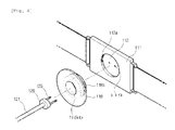
Fig. 4 is a view illustrating a process of combining a measurement rod with the body unit of a device for measuring bladder pressure according to the present invention; -
Fig. 5 is a perspective view illustrating the configuration of a device for measuring bladder pressure according to another embodiment of the present invention; and -
Fig. 6 is a view illustrating a process of using a device for measuring bladder pressure according to another embodiment of the present invention. -
- 100: device for measuring bladder pressure
- 110: body unit 111: body 113: display unit
- 115: input unit 116: storage unit 117: belt
- 119: adapter 120: measurement rod
- 121: rod body 123: bladder pressure measurement unit
- 125: first abdominal pressure measurement unit
- 127: second abdominal pressure measurement unit
- 128: connector support 129: connector
- 130: guide tube 131: guide tube body
- 133: lower opening 135: upper opening
- 137: first measurement unit exposing hole
- 139: second measurement unit exposing hole
- 140: penetrating needle 141: needle body
- 143: needle 145: support rod 150: guide needle
- 151: guide needle body 155: discharge slit.
- Preferred embodiments of the present invention will be described with reference to the accompanying drawings below in order to provide a better understanding of the present invention. The embodiments of the present invention can be implemented in various forms, and should not be interpreted as being limited to the embodiments described in detail below. These embodiments are provided such that this disclosure will be thorough and complete and will fully convey the concept of the invention to those skilled in the art. Accordingly, the shape and the like of elements in the drawings may be exaggerated in order to clearly illustrate features of the embodiments. In the drawings, like components are denoted by like reference numerals. In the following description, the detailed description of known functions and configurations incorporated herein will be omitted when it may obscure the subject matter of the present invention.
-
Fig. 1 is a perspective view illustrating the configuration of a bladderpressure measurement device 100 according to the present invention, andFig. 2 is a view illustrating the assembled state of the bladderpressure measurement device 100. - As shown in the drawings, the bladder
pressure measurement device 100 according to the present invention includes abody unit 110 configured to be worn on the waist of a user, ameasurement rod 120 configured to be inserted into the abdomen of the user and to measure abdominal pressure and bladder pressure, aguide tube 130 configured to guide the insertion of themeasurement rod 120 into the abdomen, and a penetrating needle 140 configured to form an insertion hole in the abdomen and allow themeasurement rod 120 to be inserted into the abdomen. In addition, although not shown in the drawings, the bladderpressure measurement device 100 includes a sphincter electromyography unit (not shown) that is attached to the skin neighboring sphincters and measures the electromyographic activity of sphincters. - The
body unit 110 is connected with themeasurement rod 120, and calculates actual detrusor pressure based on the measured bladder pressure and abdominal pressure. Thebody unit 110 includes abody 111 disposed on the abdomen; adisplay unit 113 configured to be provided on the front side of thebody 111 to display the measured bladder pressure and abdominal pressure, the measured electromyographic activity and the calculated detrusor pressure; aninput unit 115 configured to receive an input signal from the user; a storage unit 116 configured to provided in thebody 111 and store the measured bladder pressure and abdominal pressure, the measured electromyographic activity and the calculated detrusor pressure; abelt 117 or patch configured to fasten thebody 111 to the abdomen of the user; anadapter 119 electrically connected with themeasurement rod 120; and alength control bracket 118 configured to control the depth of insertion of themeasurement rod 120 into the abdomen. - In this case, the
body unit 110 may be operated by applying power through a power supply line (not shown), or may include a battery (not shown) for supplying power. - The
body 111 is formed in a hull shape having a specific size. Thebody 111 is formed of a durable material so that it can be repeatedly used over a long period of time. Thebody 111 includes adisplay unit 113, aninput unit 115, a storage unit 116, anadapter 119, a control unit (not shown) configured to control themeasurement rod 120, and a connection (not shown) with a computer mainframe that can be connected separately. - The
display unit 113 displays the bladder pressure and abdominal pressure measured by themeasurement rod 120, the sphincter electromyographic activity measured by a sphincter electromyography unit (not shown), and the detrusor pressure calculated by a control unit (not shown). This enables a user or a doctor to easily become aware of the current bladder pressure of the user. - The
input unit 115 receives an input signal associated with the driving of thebody unit 110 and themeasurement rod 120. Theinput unit 115 may be embodied in the form of a plurality of buttons integrated with thebody unit 110, and may include a separate wireless control unit (not shown), such as a remote control, so as to enable an inputting person to conveniently input signals. - In this case, the inputting person may be a subject, a doctor, or a nurse.
- The
input unit 115 and the wireless control unit (not shown) may include a power button, a reset button configured to restore factory default settings, a history button configured to allow bladder pressure particulars, stored in the storage unit 116, to be displayed on thedisplay unit 113, etc. - In the storage unit 116, the measured bladder pressure and abdominal pressure, the measured electromyographic activity and the calculated detrusor pressure are stored on a per-time period basis. The user can view information, stored in the storage unit 116, via the
display unit 113 or the monitor of a separately connected computer mainframe. - The
belt 117 or the patch allows the user to fasten thebody 111 to the abdomen in order to measure bladder pressure. Through thebelt 117 or the patch, thebody 111 is securely fastened to the abdomen of the user, and in this state, is connected to themeasurement rod 120. Thebelt 117 may be provided in the form of an elastic ring, as shown in the drawings, may be provided so that both ends are coupled to each other by a fastening member (not shown), or may be attached to the abdomen in a patch form. - As shown in
Fig. 4 , theadapter 119 is provided on the backside of thebody 111. Theadaptor 119 is electrically connected with theconnector 129 of themeasurement rod 120 inserted into the abdomen so that the bladder pressure and abdominal pressure measured by themeasurement rod 120 are transferred to a control unit (not shown). - The
length control bracket 118 is provided such that theconnector 129 is inserted therein and passed therethrough, and is coupled to the backside of thebody 111. Theconnector 129 is inserted therein and electrically connected to theadapter 119 that is provided on the backside of thebody 111. - Depending on the depth to which the
length control bracket 118 is inserted into theinsertion groove 112 of thebody 111, the depth to which the abdominalpressure measurement units measurement rod 120 are inserted into the abdomen, that is, the abdominal pressure measurement position, is controlled. - On the inner circumferential surface of the
insertion groove 112 and the outer circumferential surface of thelength control bracket 118, male andfemale screw threads insertion groove 112 and thelength control bracket 118, the length by which themeasurement rod 120 is inserted into the abdomen of the user can be controlled. - The
measurement rod 120 is inserted into the abdomen of the user, and measures bladder pressure and abdominal pressure occurring during bladder filling and urination. Themeasurement rod 120 includes arod body 121; a bladderpressure measurement unit 123 configured to be provided at the lower end of therod body 121 to measure bladder pressure; a first abdominalpressure measurement unit 125 provided to be spaced apart from the bladderpressure measurement unit 123 by a specific distance to measure abdominal pressure; a second abdominalpressure measurement unit 127 provided to be spaced apart from the first abdominalpressure measurement unit 125 to measure abdominal pressure; aconnector 129 electrically connected to thebody unit 110; and aconnector support 128 configured to support theconnector 129. - The
rod body 121 is formed in a rod shape having a specific length, and is formed to have elasticity so that it will not damage the inner wall of the bladder. Therod body 121 is inserted into the abdomen of the user in the state in which it is received in aguide tube 130. Therod body 121 is formed to be longer than theguide tube 130 so that thelower end 121a and the bladderpressure measurement unit 123 can be exposed from the lower end of theguide tube 130. - The bladder
pressure measurement unit 123 is provided at the lower end of therod body 121, and measures bladder pressure. The bladderpressure measurement unit 123 is provided at a position that allows the bladderpressure measurement unit 123 to come into contact with the bladder, and measures changes in bladder pressure during bladder filling and urination. The bladderpressure measurement unit 123 is provided in the form of a pressure sensor, and bladder pressure measured by the bladderpressure measurement unit 123 is transferred to thebody 111 through theconnector 129. - The first abdominal
pressure measure unit 125 and the second abdominalpressure measure unit 127 are disposed to be spaced apart from each other, and measures abdominal pressure. The first abdominalpressure measure unit 125 and the second abdominalpressure measure unit 127 are provided on therod body 121 to come into contact with the abdomen of the user. Using these units, abdominal pressure that is applied to the abdomen during bladder filling and urination is measured. The first abdominalpressure measure unit 125 and the second abdominalpressure measure unit 127 are provided in the form of a pressure sensor, and abdominal pressures measured thereby are transferred to thebody 111. - The abdominal
pressure measure unit 125 and the second abdominalpressure measure unit 127 may simultaneously measure pressures occurring in different abdominal layers, thereby determining the depth of insertion of the measurement rod, or may be used alternately to measure pressure, thereby increasing the accuracy of measurement. The use of each of the abdominalpressure measure unit 125 and the second abdominalpressure measure unit 127 may be set by a user via theinput unit 115, or can be automatically determined through comparison with the pressure measured by the bladderpressure measurement unit 123. This can be used to determine an abdominal pressure measurement unit that measures abdominal pressure through automatic comparison with the pressure measured by the bladderpressure measurement unit 123 when the depth of a site to be measured for abdominal pressure is changed by urination or a change in abdominal pressure. - The
connector support 128 is provided at the upper end of therod body 121 and support theconnector 129 and therod body 121. Theconnector support 128 is formed to have a diameter larger than that of therod body 121. Accordingly, even when themeasurement rod 120 is inserted into theguide tube 130, theconnector support 128 limits the length of insertion of therod body 121 in the state in which it has been placed at the upper end of theguide tube 130. - As shown in
Fig. 4 , theconnector 129 is inserted into theadapter 119 of thebody 111. In this case, the bladderpressure measurement device 100 according to a preferred embodiment of the present invention is configured such that theconnector 129 is provided in the form of a rod having a specific length, and theadapter 119 is provided in the form of an insertion groove into which the rod is to be inserted. However, on the contrary, in some cases, the connector may be provided in the form of an insertion groove, and theadapter 119 may be provided in the form of a rod. - The
guide tube 130 guides the penetrating needle 140 through the penetration of into the abdomen of the user, and guides themeasurement rod 120 through the insertion of into the abdomen of the user after the removal of the penetrating needle 140. - The
guide tube 130 includes a hollow-shapedguide tube body 131 open at the upper and lower ends; and measurementunit exposing holes guide tube body 131 in the axial direction of theguide tube body 131 at positions corresponding to the positions of the abdominalpressure measurement units 125 and127. - The
guide tube 130 is formed to have an inner diameter larger than the outer diameter of the penetrating needle 140 and the outer diameter of therod body 121. Accordingly, the penetrating needle 140 and therod body 121 can be easily inserted into theguide tube 130. Theguide tube 130 may be formed of a polymer material or a biodegradable material. - As shown in
Fig. 2 , the first measurementunit exposing hole 137 and the second measurementunit exposing hole 139 allow the first abdominalpressure measurement unit 125 and the second abdominalpressure measurement unit 127 to be exposed to the outside of theguide tube 130 when themeasurement rod 120 is received in theguide tube 130. Alternatively, when theguide tube 130 is formed of a biodegradable material, it will be easily degraded by body fluids even in the absence of the measurement unit exposing units, and thus will be degraded within a short time after its insertion into the abdomen. Accordingly, the first abdominalpressure measurement unit 125 and the second abdominalpressure measurement unit 127 can measure abdominal pressure while in direct contact with the abdominal wall. - The penetrating needle 140 penetrates the abdomen of the user in combination with the
guide tube 130 and forms an insertion hole (not shown) having a specific size, into which themeasurement rod 120 is to be inserted. The penetrating needle 140 includes aneedle body 141 formed of a rigid metal material; aneedle 143 configured to be formed sharply at the lower end of theneedle body 141 and penetrate the abdomen; and asupport rod 145 configured to serve as a handle and limit the depth of insertion of the penetrating needle 140. - The
needle body 141 is formed of a metal material. The penetrating needle 140 penetrates the abdomen under pressure, applied to the abdomen of the user, in the state in which it has been inserted into theguide tube 130. The penetrating needle 140 is separated from theguide tube 130 after it has formed an insertion hole (not shown) in the abdomen. - A process of using the bladder
pressure measurement device 100 according to the present invention, which has the above-described configuration, is now described with reference toFigs. 1 to 4 . - As shown in
Fig. 3(a) , a user prepares themeasurement rod 120, theguide tube 130, and the penetrating needle 140. Then, as shown inFig. 3(b) , the penetrating needle 140 is inserted into theguide tube 130. At this time, theneedle 143 of the penetrating needle 140 is exposed from the lower end of theguide tube 130 because thelength 12 of the penetrating needle 140 is longer than the length 11 of theguide tube 130. - The
guide tube 130 including the penetrating needle 140 received therein is gripped by the user's hand and pressed against the abdomen. Then, theneedle 143 penetrates the abdomen, and the penetrating needle 140 and theguide tube 130 are inserted into the abdomen. - In this state in which the
guide tube 130 and the penetrating needle 140 have been inserted into the abdomen, the penetrating needle 140 is separated from theguide tube 130 by the user's hand. - Then, as shown in
Fig. 3(c) , themeasurement rod 120 is inserted into theguide tube 130 inserted into the abdomen. The lower end of themeasurement rod 120 is inserted into the abdomen to a specific depth through an insertion hole (not shown), and is inserted into the bladder. In the state in which themeasurement rod 120 has been inserted into theguide tube 130 as shown inFig. 3(d) , a user wears thebody unit 110 on his or her waist, connects theconnector 129 to theadapter 119 as shown inFig. 4 , controls the appropriate depth of insertion of themeasurement rod 120 by controlling the screw coupling length of thelength control bracket 118 while checking pressure, and then fastens the body unit to the abdomen using thebelt 117 or a patch (not shown). - Meanwhile, a sphincter electromyography unit (not shown) is attached to the skin neighboring the sphincter of the user. The sphincter electromyography unit (not shown) is provided as a patch-type electrical sensor.
- When power is applied, the bladder
pressure measurement unit 123 measures bladder pressure, and the first abdominalpressure measurement unit 125 and the second abdominalpressure measurement unit 127 measure abdominal pressure. A sphincter electromyography unit (not shown) measures sphincter electromyographic activity. The measured bladder pressure, abdominal pressure and electromyographic activity are transferred to thebody unit 110, and a control unit (not shown) calculates detrusor pressure by subtracting the measured abdominal pressure from the measured bladder pressure. The determined detrusor pressure is stored in thebody unit 110 on a per-time period basis, and the stored information can be viewed via a separately connected computer mainframe (not shown). - The
measurement rod 120 is securely fastened to thebody unit 110 in the state in which it has been inserted in the abdomen along with theguide tube 130, and thebody unit 110 is fastened to the abdomen by thebelt 117 or a patch. Accordingly, bladder pressure can be accurately measured for a specific period of time without considerably limiting the activity of the user. - Therefore, whether bladder function is abnormal can be accurately determined.
- Meanwhile,
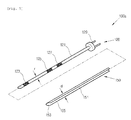
Fig. 5 is a perspective view illustrating the configuration of a bladderpressure measurement device 100a according to another embodiment of the present invention. - The above-described bladder
pressure measurement device 100 is configured such that the penetrating needle 140 is first inserted into theguide tube 130 and forms an insertion hole (not shown) and then themeasurement rod 120 is inserted into theguide tube 130 after the separation of the penetrating needle 140. In contrast, a bladderpressure measurement device 100a according to another embodiment of the present invention is configured such that themeasurement rod 120 is inserted into aguide needle 150 that functions as both a penetrating needle and a guide tube. - The
guide needle 150 includes aguide needle body 151 formed of a metal material, and adischarge slit 155 formed on the side in the axial direction of theguide needle body 151 to have a specific width. - The discharge slit 155 is formed to be larger than the diameter of the
measurement rod 120 and thus allows theguide needle 150 to be easily separated from themeasurement rod 120. -
Fig. 6 is a view illustrating a process of using a bladderpressure measurement device 100a according to another embodiment of the present invention. - As shown in
Fig. 6(a) , themeasurement rod 120 is first inserted into theguide needle 150. In this case, the length of theguide needle 150 is longer than that of themeasurement rod 120. Thelower end 153 of theguide needle 150 is formed in a sharp needle shape. - A user presses the
guide needle 150 having themeasurement rod 120 received therein against the abdomen of the user, thereby forming an insertion hole (not shown) in the abdomen. At the same time, themeasurement rod 120 is inserted into the insertion hole (not shown). After the lower end of themeasurement rod 120 has been inserted into the abdomen to a specific depth, theguide needle 150 is separated and discharged from themeasurement rod 120 as shown inFig. 6(b) . - A user presses the
guide needle 150 with the side of themeasurement rod 120 and thus allows the discharge slit 155 of theguide needle 150 to be separated from themeasurement rod 120. - Accordingly, in the state in which only the
measurement rod 120 has been inserted into the abdomen, it is connected to thebody unit 110 and measures bladder pressure and abdominal pressure. - Meanwhile, in the above-described bladder pressure measurement device according to the present invention, the guide tube and the measurement rod are used together, or the guide tube, the penetrating needle and the measurement rod are used together. However, in some cases, only the measurement rod may be implemented. In this case, the measurement rod may be formed of a metal material in order to facilitate the penetration thereof into the abdomen.
- As described above, the bladder pressure measurement device according to the present invention can measure bladder pressure together with abdominal pressure and sphincter electromyographic activity in the state in which the measurement rod has been inserted into the abdomen of the user, and thus can accurately calculate actual detrusor pressure, exclusive of abdominal pressure.
- Furthermore, an insertion hole can be easily formed in the abdomen by using the guide tube and the penetrating needle, and then the measurement rod can be inserted therein. Furthermore, the body unit is securely fastened to the abdomen of the user by a belt or a patch. Moreover, a user can measure bladder pressure in a convenient and accurate manner.
- The above-described embodiments of the bladder pressure measurement device according to the present invention are illustrative only, and any person having ordinary knowledge in the art to the present invention pertains will appreciate that various modifications and other equivalent embodiments are possible. Accordingly, it can be easily understood that the scope of the present invention is not limited only to the embodiments set forth in the detailed description above. Therefore, the true technical range of protection of the present invention should be determined by the technical spirit of the attached claims. In addition, it should be understood that the scope of the present invention include all modifications, equivalents and replacements that fall within the spirit and scope of the invention that are defined by the attached claims.
Claims (14)
- A device for measuring bladder pressure, comprising:a measurement rod configured to be inserted into an abdomen of a user, to measure both abdominal pressure and bladder pressure; anda body unit configured to be worn on a waist of the user, and be electrically connected with the measurement rod, to calculate and store detrusor pressure obtained by subtracting the measured abdominal pressure from the bladder pressure measured by the measurement rod.
- The device of claim 1, further comprising a guide tube configured to penetrate and be inserted into the abdomen of the user, and receive the measurement rod within it, to guide the measurement rod.
- The device of claim 2, wherein the body unit comprises:a body having a display unit and an input unit;an adapter provided on the backside of the body to come into contact with the abdomen of the user, to be electrically connected with the measurement rod; anda belt coupled to both sides of the body, and configured to be worn on the waist of the user.
- The device of claim 3, further comprising a wireless control unit configured to be separate from the body unit, to enable an inputting person to input signals using buttons.
- The device of claim 3, wherein the measurement rod comprises:a rod body having a predetermined length;a bladder pressure measurement unit configured to be provided at a lower end of the rod body, to measure the bladder pressure of the user;an abdominal pressure measurement unit configured to be spaced apart from the bladder pressure measurement unit, to measure the abdominal pressure of the user; anda connector configured to be provided at an upper end of the rod unit, and to be connected to the adapter.
- The device of claim 5, further comprising a length control bracket configured to be screw-coupled with the backside of the body, to control depth of insertion of the measurement rod;
wherein the position within the abdomen, into which the abdominal pressure measurement unit is inserted, is controlled by controlling the screw coupling length between the length control bracket and the body. - The device of claim 2, wherein the guide tube is formed of a metal material, and is configured such that a sharp needle is formed at the lower end of the guide tube and a discharge slit from which the measurement rod can be separated is formed along the axial direction of the guide tube to have a diameter larger than that of the measurement rod.
- The device of claim 2, wherein the guide tube is formed of a polymer material or a metal material.
- The device of claim 8, wherein the guide tube is formed of a biodegradable polymer material that is degraded by body fluids.
- The device of claim 9, further comprising a penetrating needle configured to be inserted into the guide tube, penetrate the abdomen of the user through guidance of the guide tube and then form an insertion hole through which the measurement rod is inserted when the guide tube is formed of the biodegradable polymer material.
- The device of claim 10, wherein the penetrating needle is separated from the guide tube after its penetration into the abdomen of the user, and then the measurement rod is inserted into the abdomen through the guide tube.
- The device of claim 5, wherein a measurement unit exposing hole having a predetermined size is formed penetrating through the outer circumferential surface of the guide tube at a position corresponding to the position of the abdominal pressure measurement unit.
- The device of claim 5, wherein the abdominal pressure measurement unit comprises a plurality of abdominal pressure measurement units spaced apart from each other.
- The device of claim 1, wherein the device further comprises a sphincter electromyography unit configured to be attached to a sphincter side of the user, to measure sphincter electromyographic activity; wherein the body unit determines the normality of the organic motion of detrusor and sphincter muscles based on the measured sphincter electromyographic activity.
Applications Claiming Priority (2)
| Application Number | Priority Date | Filing Date | Title |
|---|---|---|---|
| KR1020130045039A KR101380893B1 (en) | 2013-04-23 | 2013-04-23 | Measurement device for urinary detrusor pressure |
| PCT/KR2014/003386 WO2014175601A1 (en) | 2013-04-23 | 2014-04-18 | Device for measuring urinary detrusor pressure |
Publications (3)
| Publication Number | Publication Date |
|---|---|
| EP2989982A1 true EP2989982A1 (en) | 2016-03-02 |
| EP2989982A4 EP2989982A4 (en) | 2017-01-11 |
| EP2989982B1 EP2989982B1 (en) | 2019-07-17 |
Family
ID=50656391
Family Applications (1)
| Application Number | Title | Priority Date | Filing Date |
|---|---|---|---|
| EP14787941.5A Active EP2989982B1 (en) | 2013-04-23 | 2014-04-18 | Device for measuring urinary detrusor pressure |
Country Status (5)
| Country | Link |
|---|---|
| US (1) | US9795336B2 (en) |
| EP (1) | EP2989982B1 (en) |
| KR (1) | KR101380893B1 (en) |
| CN (1) | CN104717922B (en) |
| WO (1) | WO2014175601A1 (en) |
Cited By (2)
| Publication number | Priority date | Publication date | Assignee | Title |
|---|---|---|---|---|
| EP3060108B1 (en) * | 2013-10-25 | 2022-11-23 | Sintef TTO AS | In-vivo pressure monitoring system |
| KR20230076511A (en) * | 2021-11-24 | 2023-05-31 | 한국전자기술연구원 | Sensor for abdominal pressure measurement |
Families Citing this family (10)
| Publication number | Priority date | Publication date | Assignee | Title |
|---|---|---|---|---|
| CN104665850A (en) * | 2015-03-27 | 2015-06-03 | 江苏苏云医疗器材有限公司 | Training device for evaluating pressure and volume of bladder |
| WO2016176590A1 (en) * | 2015-04-29 | 2016-11-03 | The Cleveland Clinic Foundation | Bladder event detection for diagnosis of urinary incontinence or treatment of lower urinary tract dysfunction |
| KR101866647B1 (en) | 2016-07-13 | 2018-06-11 | 암페놀센싱코리아 유한회사 | Measurement device for urinary detrusor pressure |
| US10485483B1 (en) * | 2016-10-17 | 2019-11-26 | Srs Medical Systems, Llc | Diagnostic drainage catheter assembly and methods |
| CN107625528A (en) * | 2017-11-23 | 2018-01-26 | 刘辉辉 | Bladder urine volume detection alarm integrated device |
| CN108836368B (en) * | 2018-05-10 | 2024-04-16 | 浙江神造科技有限公司 | A method and device for predicting urination based on electromyography and micro-pressure signals |
| CN110301915A (en) * | 2019-05-14 | 2019-10-08 | 武汉闻道复兴智能科技有限责任公司 | A kind of bladder muscle electrical signal detection device and detection system |
| CN114632256B (en) * | 2022-03-10 | 2023-07-04 | 四川省医学科学院·四川省人民医院 | Bladder capacity expanding device |
| WO2023243745A1 (en) * | 2022-06-16 | 2023-12-21 | 사피엔메드 주식회사 | Urodynamic study apparatus for controlling sensor location |
| CN117717341B (en) * | 2023-07-31 | 2024-11-05 | 上海市第四人民医院 | Intelligent judging method and device for urinary retention |
Family Cites Families (15)
| Publication number | Priority date | Publication date | Assignee | Title |
|---|---|---|---|---|
| US3742958A (en) * | 1971-04-21 | 1973-07-03 | C Rundles | Suprapubic catheter inserter |
| US4612939A (en) * | 1984-10-15 | 1986-09-23 | Robertson Jack R | Method for diagnosis of stress incontinence in women |
| US5167237A (en) * | 1991-07-09 | 1992-12-01 | Long Island Jewish Medical Center | Apparatus for monitoring detrusor pressure exerted by a bladder |
| KR20030081323A (en) * | 2000-10-23 | 2003-10-17 | 에디컨인코포레이티드 | Apparatus and method for measurement and assessment of sling-tension for treatment of female urinary incontinence |
| US6931276B2 (en) * | 2002-04-29 | 2005-08-16 | Tomi Streng | Method and device for use in micturition studies |
| KR20030090171A (en) * | 2002-05-21 | 2003-11-28 | 서정환 | ambulatory monitoring device for bladder pressure and bladder neck pressure |
| US7979137B2 (en) * | 2004-02-11 | 2011-07-12 | Ethicon, Inc. | System and method for nerve stimulation |
| KR100691731B1 (en) * | 2004-08-27 | 2007-03-12 | 송철규 | Urethral Catheter and Portable Urodynamic Monitoring Device |
| KR100689097B1 (en) | 2006-06-07 | 2007-03-02 | (주)뉴로네이드 | Urinary incontinence diagnostic device |
| KR20080100658A (en) * | 2007-05-14 | 2008-11-19 | 한국전자통신연구원 | Belt with health care function |
| KR100948826B1 (en) | 2008-01-28 | 2010-03-22 | 전북대학교산학협력단 | Abdominal pressure measurement method using surface electromyography |
| CA2748021C (en) | 2008-12-22 | 2016-08-16 | Pneumoflex Systems, Llc | Involuntary contraction induced pressure as a medical diagnostic tool using involuntary reflex cough test |
| DE102009017034B3 (en) * | 2009-04-09 | 2010-06-17 | Pulsion Medical Systems Ag | Device for measuring the bubble pressure |
| KR100984807B1 (en) | 2009-05-18 | 2010-10-01 | 서울대학교산학협력단 | Urodynamic measurement apparatus |
| CN102631191B (en) | 2012-03-27 | 2014-04-23 | 苏州达维生物医药有限公司 | System and method for monitoring bladder pressure and abdominal pressure |
-
2013
- 2013-04-23 KR KR1020130045039A patent/KR101380893B1/en not_active Expired - Fee Related
-
2014
- 2014-04-18 WO PCT/KR2014/003386 patent/WO2014175601A1/en not_active Ceased
- 2014-04-18 US US14/411,603 patent/US9795336B2/en not_active Expired - Fee Related
- 2014-04-18 CN CN201480001713.8A patent/CN104717922B/en active Active
- 2014-04-18 EP EP14787941.5A patent/EP2989982B1/en active Active
Cited By (2)
| Publication number | Priority date | Publication date | Assignee | Title |
|---|---|---|---|---|
| EP3060108B1 (en) * | 2013-10-25 | 2022-11-23 | Sintef TTO AS | In-vivo pressure monitoring system |
| KR20230076511A (en) * | 2021-11-24 | 2023-05-31 | 한국전자기술연구원 | Sensor for abdominal pressure measurement |
Also Published As
| Publication number | Publication date |
|---|---|
| EP2989982B1 (en) | 2019-07-17 |
| US20160058355A1 (en) | 2016-03-03 |
| US9795336B2 (en) | 2017-10-24 |
| WO2014175601A1 (en) | 2014-10-30 |
| KR101380893B1 (en) | 2014-04-02 |
| CN104717922A (en) | 2015-06-17 |
| EP2989982A4 (en) | 2017-01-11 |
| CN104717922B (en) | 2017-03-29 |
Similar Documents
| Publication | Publication Date | Title |
|---|---|---|
| US9795336B2 (en) | Device for measuring urinary detrusor pressure | |
| US12295732B2 (en) | Devices, systems, and methods for monitoring bladder function | |
| US20190133473A1 (en) | Systems, devices and methods for assessment of body cavity pressures | |
| JP2024507880A (en) | Self-learning and non-invasive bladder monitoring system and method | |
| KR100984807B1 (en) | Urodynamic measurement apparatus | |
| US10413231B2 (en) | Orifice probe apparatus and a method of use thereof | |
| NZ229633A (en) | Electrical apparatus for sensing body cavity pressure and stimulating body cavity muscles | |
| US20140058284A1 (en) | Nerve monitoring system | |
| JP7242688B2 (en) | urodynamic tester | |
| CN106308824B (en) | A wireless urodynamic instrument for continuous monitoring of bladder function | |
| CN111345829B (en) | Novel bladder pressure test device | |
| KR100691731B1 (en) | Urethral Catheter and Portable Urodynamic Monitoring Device | |
| KR20210036643A (en) | System for monitoring patient | |
| CN220876770U (en) | Experimental device for forcing saccule | |
| KR101519608B1 (en) | Measurement rod of measurement device for urinary detrusor pressure | |
| CN111493902B (en) | Portable anal manometer | |
| EP4382045A1 (en) | Neuroelectrophysiological monitoring device | |
| CN221106555U (en) | An intelligent abdominal puncture drainage control device | |
| CN207118902U (en) | A bladder detector | |
| KR100689097B1 (en) | Urinary incontinence diagnostic device | |
| CN115530789A (en) | Wearable device capable of perceiving and treating excessive bladder filling | |
| CN106725540B (en) | Bladder detector and use method thereof | |
| GB2613596A (en) | Manometer | |
| CA2661399A1 (en) | Accessible incontinence control device | |
| HK1172813B (en) | Systems, devices and methods for assessment of body cavity pressures |
Legal Events
| Date | Code | Title | Description |
|---|---|---|---|
| PUAI | Public reference made under article 153(3) epc to a published international application that has entered the european phase |
Free format text: ORIGINAL CODE: 0009012 |
|
| 17P | Request for examination filed |
Effective date: 20151111 |
|
| AK | Designated contracting states |
Kind code of ref document: A1 Designated state(s): AL AT BE BG CH CY CZ DE DK EE ES FI FR GB GR HR HU IE IS IT LI LT LU LV MC MK MT NL NO PL PT RO RS SE SI SK SM TR |
|
| AX | Request for extension of the european patent |
Extension state: BA ME |
|
| DAX | Request for extension of the european patent (deleted) | ||
| A4 | Supplementary search report drawn up and despatched |
Effective date: 20161213 |
|
| RIC1 | Information provided on ipc code assigned before grant |
Ipc: A61B 5/20 20060101AFI20161207BHEP Ipc: A61B 5/0488 20060101ALI20161207BHEP |
|
| REG | Reference to a national code |
Ref country code: DE Ref legal event code: R079 Ref document number: 602014050192 Country of ref document: DE Free format text: PREVIOUS MAIN CLASS: A61B0005200000 Ipc: A61B0005000000 |
|
| GRAP | Despatch of communication of intention to grant a patent |
Free format text: ORIGINAL CODE: EPIDOSNIGR1 |
|
| STAA | Information on the status of an ep patent application or granted ep patent |
Free format text: STATUS: GRANT OF PATENT IS INTENDED |
|
| RIC1 | Information provided on ipc code assigned before grant |
Ipc: A61B 5/00 20060101AFI20190116BHEP Ipc: A61B 5/20 20060101ALI20190116BHEP Ipc: A61B 5/0488 20060101ALI20190116BHEP |
|
| INTG | Intention to grant announced |
Effective date: 20190214 |
|
| GRAS | Grant fee paid |
Free format text: ORIGINAL CODE: EPIDOSNIGR3 |
|
| GRAA | (expected) grant |
Free format text: ORIGINAL CODE: 0009210 |
|
| STAA | Information on the status of an ep patent application or granted ep patent |
Free format text: STATUS: THE PATENT HAS BEEN GRANTED |
|
| AK | Designated contracting states |
Kind code of ref document: B1 Designated state(s): AL AT BE BG CH CY CZ DE DK EE ES FI FR GB GR HR HU IE IS IT LI LT LU LV MC MK MT NL NO PL PT RO RS SE SI SK SM TR |
|
| REG | Reference to a national code |
Ref country code: GB Ref legal event code: FG4D |
|
| REG | Reference to a national code |
Ref country code: CH Ref legal event code: EP |
|
| REG | Reference to a national code |
Ref country code: IE Ref legal event code: FG4D |
|
| REG | Reference to a national code |
Ref country code: DE Ref legal event code: R096 Ref document number: 602014050192 Country of ref document: DE |
|
| REG | Reference to a national code |
Ref country code: AT Ref legal event code: REF Ref document number: 1155070 Country of ref document: AT Kind code of ref document: T Effective date: 20190815 |
|
| REG | Reference to a national code |
Ref country code: NL Ref legal event code: MP Effective date: 20190717 |
|
| REG | Reference to a national code |
Ref country code: LT Ref legal event code: MG4D |
|
| REG | Reference to a national code |
Ref country code: AT Ref legal event code: MK05 Ref document number: 1155070 Country of ref document: AT Kind code of ref document: T Effective date: 20190717 |
|
| PG25 | Lapsed in a contracting state [announced via postgrant information from national office to epo] |
Ref country code: FI Free format text: LAPSE BECAUSE OF FAILURE TO SUBMIT A TRANSLATION OF THE DESCRIPTION OR TO PAY THE FEE WITHIN THE PRESCRIBED TIME-LIMIT Effective date: 20190717 Ref country code: PT Free format text: LAPSE BECAUSE OF FAILURE TO SUBMIT A TRANSLATION OF THE DESCRIPTION OR TO PAY THE FEE WITHIN THE PRESCRIBED TIME-LIMIT Effective date: 20191118 Ref country code: NL Free format text: LAPSE BECAUSE OF FAILURE TO SUBMIT A TRANSLATION OF THE DESCRIPTION OR TO PAY THE FEE WITHIN THE PRESCRIBED TIME-LIMIT Effective date: 20190717 Ref country code: LT Free format text: LAPSE BECAUSE OF FAILURE TO SUBMIT A TRANSLATION OF THE DESCRIPTION OR TO PAY THE FEE WITHIN THE PRESCRIBED TIME-LIMIT Effective date: 20190717 Ref country code: AT Free format text: LAPSE BECAUSE OF FAILURE TO SUBMIT A TRANSLATION OF THE DESCRIPTION OR TO PAY THE FEE WITHIN THE PRESCRIBED TIME-LIMIT Effective date: 20190717 Ref country code: BG Free format text: LAPSE BECAUSE OF FAILURE TO SUBMIT A TRANSLATION OF THE DESCRIPTION OR TO PAY THE FEE WITHIN THE PRESCRIBED TIME-LIMIT Effective date: 20191017 Ref country code: NO Free format text: LAPSE BECAUSE OF FAILURE TO SUBMIT A TRANSLATION OF THE DESCRIPTION OR TO PAY THE FEE WITHIN THE PRESCRIBED TIME-LIMIT Effective date: 20191017 Ref country code: HR Free format text: LAPSE BECAUSE OF FAILURE TO SUBMIT A TRANSLATION OF THE DESCRIPTION OR TO PAY THE FEE WITHIN THE PRESCRIBED TIME-LIMIT Effective date: 20190717 Ref country code: SE Free format text: LAPSE BECAUSE OF FAILURE TO SUBMIT A TRANSLATION OF THE DESCRIPTION OR TO PAY THE FEE WITHIN THE PRESCRIBED TIME-LIMIT Effective date: 20190717 |
|
| PG25 | Lapsed in a contracting state [announced via postgrant information from national office to epo] |
Ref country code: RS Free format text: LAPSE BECAUSE OF FAILURE TO SUBMIT A TRANSLATION OF THE DESCRIPTION OR TO PAY THE FEE WITHIN THE PRESCRIBED TIME-LIMIT Effective date: 20190717 Ref country code: IS Free format text: LAPSE BECAUSE OF FAILURE TO SUBMIT A TRANSLATION OF THE DESCRIPTION OR TO PAY THE FEE WITHIN THE PRESCRIBED TIME-LIMIT Effective date: 20191117 Ref country code: GR Free format text: LAPSE BECAUSE OF FAILURE TO SUBMIT A TRANSLATION OF THE DESCRIPTION OR TO PAY THE FEE WITHIN THE PRESCRIBED TIME-LIMIT Effective date: 20191018 Ref country code: ES Free format text: LAPSE BECAUSE OF FAILURE TO SUBMIT A TRANSLATION OF THE DESCRIPTION OR TO PAY THE FEE WITHIN THE PRESCRIBED TIME-LIMIT Effective date: 20190717 Ref country code: LV Free format text: LAPSE BECAUSE OF FAILURE TO SUBMIT A TRANSLATION OF THE DESCRIPTION OR TO PAY THE FEE WITHIN THE PRESCRIBED TIME-LIMIT Effective date: 20190717 Ref country code: AL Free format text: LAPSE BECAUSE OF FAILURE TO SUBMIT A TRANSLATION OF THE DESCRIPTION OR TO PAY THE FEE WITHIN THE PRESCRIBED TIME-LIMIT Effective date: 20190717 |
|
| PG25 | Lapsed in a contracting state [announced via postgrant information from national office to epo] |
Ref country code: TR Free format text: LAPSE BECAUSE OF FAILURE TO SUBMIT A TRANSLATION OF THE DESCRIPTION OR TO PAY THE FEE WITHIN THE PRESCRIBED TIME-LIMIT Effective date: 20190717 |
|
| PG25 | Lapsed in a contracting state [announced via postgrant information from national office to epo] |
Ref country code: EE Free format text: LAPSE BECAUSE OF FAILURE TO SUBMIT A TRANSLATION OF THE DESCRIPTION OR TO PAY THE FEE WITHIN THE PRESCRIBED TIME-LIMIT Effective date: 20190717 Ref country code: PL Free format text: LAPSE BECAUSE OF FAILURE TO SUBMIT A TRANSLATION OF THE DESCRIPTION OR TO PAY THE FEE WITHIN THE PRESCRIBED TIME-LIMIT Effective date: 20190717 Ref country code: IT Free format text: LAPSE BECAUSE OF FAILURE TO SUBMIT A TRANSLATION OF THE DESCRIPTION OR TO PAY THE FEE WITHIN THE PRESCRIBED TIME-LIMIT Effective date: 20190717 Ref country code: DK Free format text: LAPSE BECAUSE OF FAILURE TO SUBMIT A TRANSLATION OF THE DESCRIPTION OR TO PAY THE FEE WITHIN THE PRESCRIBED TIME-LIMIT Effective date: 20190717 Ref country code: RO Free format text: LAPSE BECAUSE OF FAILURE TO SUBMIT A TRANSLATION OF THE DESCRIPTION OR TO PAY THE FEE WITHIN THE PRESCRIBED TIME-LIMIT Effective date: 20190717 |
|
| PG25 | Lapsed in a contracting state [announced via postgrant information from national office to epo] |
Ref country code: IS Free format text: LAPSE BECAUSE OF FAILURE TO SUBMIT A TRANSLATION OF THE DESCRIPTION OR TO PAY THE FEE WITHIN THE PRESCRIBED TIME-LIMIT Effective date: 20200224 Ref country code: SK Free format text: LAPSE BECAUSE OF FAILURE TO SUBMIT A TRANSLATION OF THE DESCRIPTION OR TO PAY THE FEE WITHIN THE PRESCRIBED TIME-LIMIT Effective date: 20190717 Ref country code: CZ Free format text: LAPSE BECAUSE OF FAILURE TO SUBMIT A TRANSLATION OF THE DESCRIPTION OR TO PAY THE FEE WITHIN THE PRESCRIBED TIME-LIMIT Effective date: 20190717 Ref country code: SM Free format text: LAPSE BECAUSE OF FAILURE TO SUBMIT A TRANSLATION OF THE DESCRIPTION OR TO PAY THE FEE WITHIN THE PRESCRIBED TIME-LIMIT Effective date: 20190717 |
|
| REG | Reference to a national code |
Ref country code: DE Ref legal event code: R097 Ref document number: 602014050192 Country of ref document: DE |
|
| PLBE | No opposition filed within time limit |
Free format text: ORIGINAL CODE: 0009261 |
|
| STAA | Information on the status of an ep patent application or granted ep patent |
Free format text: STATUS: NO OPPOSITION FILED WITHIN TIME LIMIT |
|
| PG2D | Information on lapse in contracting state deleted |
Ref country code: IS |
|
| 26N | No opposition filed |
Effective date: 20200603 |
|
| PG25 | Lapsed in a contracting state [announced via postgrant information from national office to epo] |
Ref country code: SI Free format text: LAPSE BECAUSE OF FAILURE TO SUBMIT A TRANSLATION OF THE DESCRIPTION OR TO PAY THE FEE WITHIN THE PRESCRIBED TIME-LIMIT Effective date: 20190717 |
|
| PG25 | Lapsed in a contracting state [announced via postgrant information from national office to epo] |
Ref country code: MC Free format text: LAPSE BECAUSE OF FAILURE TO SUBMIT A TRANSLATION OF THE DESCRIPTION OR TO PAY THE FEE WITHIN THE PRESCRIBED TIME-LIMIT Effective date: 20190717 |
|
| REG | Reference to a national code |
Ref country code: CH Ref legal event code: PL |
|
| PG25 | Lapsed in a contracting state [announced via postgrant information from national office to epo] |
Ref country code: LI Free format text: LAPSE BECAUSE OF NON-PAYMENT OF DUE FEES Effective date: 20200430 Ref country code: FR Free format text: LAPSE BECAUSE OF NON-PAYMENT OF DUE FEES Effective date: 20200430 Ref country code: LU Free format text: LAPSE BECAUSE OF NON-PAYMENT OF DUE FEES Effective date: 20200418 Ref country code: CH Free format text: LAPSE BECAUSE OF NON-PAYMENT OF DUE FEES Effective date: 20200430 |
|
| REG | Reference to a national code |
Ref country code: BE Ref legal event code: MM Effective date: 20200430 |
|
| PG25 | Lapsed in a contracting state [announced via postgrant information from national office to epo] |
Ref country code: BE Free format text: LAPSE BECAUSE OF NON-PAYMENT OF DUE FEES Effective date: 20200430 |
|
| GBPC | Gb: european patent ceased through non-payment of renewal fee |
Effective date: 20200418 |
|
| PG25 | Lapsed in a contracting state [announced via postgrant information from national office to epo] |
Ref country code: IE Free format text: LAPSE BECAUSE OF NON-PAYMENT OF DUE FEES Effective date: 20200418 Ref country code: GB Free format text: LAPSE BECAUSE OF NON-PAYMENT OF DUE FEES Effective date: 20200418 |
|
| REG | Reference to a national code |
Ref country code: DE Ref legal event code: R082 Ref document number: 602014050192 Country of ref document: DE Representative=s name: DEHNS GERMANY PARTNERSCHAFT MBB, DE Ref country code: DE Ref legal event code: R082 Ref document number: 602014050192 Country of ref document: DE Representative=s name: DEHNSGERMANY PARTNERSCHAFT VON PATENTANWAELTEN, DE |
|
| PG25 | Lapsed in a contracting state [announced via postgrant information from national office to epo] |
Ref country code: MT Free format text: LAPSE BECAUSE OF FAILURE TO SUBMIT A TRANSLATION OF THE DESCRIPTION OR TO PAY THE FEE WITHIN THE PRESCRIBED TIME-LIMIT Effective date: 20190717 Ref country code: CY Free format text: LAPSE BECAUSE OF FAILURE TO SUBMIT A TRANSLATION OF THE DESCRIPTION OR TO PAY THE FEE WITHIN THE PRESCRIBED TIME-LIMIT Effective date: 20190717 |
|
| PG25 | Lapsed in a contracting state [announced via postgrant information from national office to epo] |
Ref country code: MK Free format text: LAPSE BECAUSE OF FAILURE TO SUBMIT A TRANSLATION OF THE DESCRIPTION OR TO PAY THE FEE WITHIN THE PRESCRIBED TIME-LIMIT Effective date: 20190717 |
|
| REG | Reference to a national code |
Ref country code: DE Ref legal event code: R081 Ref document number: 602014050192 Country of ref document: DE Owner name: GACHON UNIVERSITY OF INDUSTRY-ACADEMIC COOPERA, KR Free format text: FORMER OWNERS: GACHON UNIVERSITY INDUSTRY-UNIVERSITY COOPERATION FOUNDATION, SEONGNAM-SI, GYEONGGI-DO, KR; GIL MEDICAL CENTER, INCHEON, KR Ref country code: DE Ref legal event code: R081 Ref document number: 602014050192 Country of ref document: DE Owner name: CHUNG, KYUNG JIN, KR Free format text: FORMER OWNERS: GACHON UNIVERSITY INDUSTRY-UNIVERSITY COOPERATION FOUNDATION, SEONGNAM-SI, GYEONGGI-DO, KR; GIL MEDICAL CENTER, INCHEON, KR |
|
| PGFP | Annual fee paid to national office [announced via postgrant information from national office to epo] |
Ref country code: DE Payment date: 20250423 Year of fee payment: 12 |
|
| REG | Reference to a national code |
Ref country code: DE Ref legal event code: R081 Ref document number: 602014050192 Country of ref document: DE Owner name: CHUNG, KYUNG JIN, KR Free format text: FORMER OWNER: GACHON UNIVERSITY OF INDUSTRY-ACADEMIC COOPERATION FOUNDATION, SEONGNAM-SI, GYEONGGI-DO, KR |