EP2989960A1 - Endoscope sheath - Google Patents
Endoscope sheath Download PDFInfo
- Publication number
- EP2989960A1 EP2989960A1 EP14873687.9A EP14873687A EP2989960A1 EP 2989960 A1 EP2989960 A1 EP 2989960A1 EP 14873687 A EP14873687 A EP 14873687A EP 2989960 A1 EP2989960 A1 EP 2989960A1
- Authority
- EP
- European Patent Office
- Prior art keywords
- hole
- endoscope
- sheath
- tubular member
- face
- Prior art date
- Legal status (The legal status is an assumption and is not a legal conclusion. Google has not performed a legal analysis and makes no representation as to the accuracy of the status listed.)
- Withdrawn
Links
- 238000003780 insertion Methods 0.000 claims abstract description 62
- 230000037431 insertion Effects 0.000 claims abstract description 62
- 238000005452 bending Methods 0.000 claims description 46
- 210000003734 kidney Anatomy 0.000 description 16
- 238000001514 detection method Methods 0.000 description 12
- XLYOFNOQVPJJNP-UHFFFAOYSA-N water Substances O XLYOFNOQVPJJNP-UHFFFAOYSA-N 0.000 description 12
- 230000002485 urinary effect Effects 0.000 description 7
- 238000000034 method Methods 0.000 description 4
- 241001164374 Calyx Species 0.000 description 3
- 230000007423 decrease Effects 0.000 description 2
- 238000005286 illumination Methods 0.000 description 2
- 238000013459 approach Methods 0.000 description 1
- 230000008602 contraction Effects 0.000 description 1
- 230000005489 elastic deformation Effects 0.000 description 1
- 239000000284 extract Substances 0.000 description 1
- 239000002184 metal Substances 0.000 description 1
- 238000012986 modification Methods 0.000 description 1
- 230000004048 modification Effects 0.000 description 1
- 229910001220 stainless steel Inorganic materials 0.000 description 1
- 239000010935 stainless steel Substances 0.000 description 1
Images



Classifications
-
- A—HUMAN NECESSITIES
- A61—MEDICAL OR VETERINARY SCIENCE; HYGIENE
- A61B—DIAGNOSIS; SURGERY; IDENTIFICATION
- A61B1/00—Instruments for performing medical examinations of the interior of cavities or tubes of the body by visual or photographical inspection, e.g. endoscopes; Illuminating arrangements therefor
- A61B1/00131—Accessories for endoscopes
- A61B1/00135—Oversleeves mounted on the endoscope prior to insertion
-
- A—HUMAN NECESSITIES
- A61—MEDICAL OR VETERINARY SCIENCE; HYGIENE
- A61B—DIAGNOSIS; SURGERY; IDENTIFICATION
- A61B1/00—Instruments for performing medical examinations of the interior of cavities or tubes of the body by visual or photographical inspection, e.g. endoscopes; Illuminating arrangements therefor
- A61B1/00112—Connection or coupling means
- A61B1/00121—Connectors, fasteners and adapters, e.g. on the endoscope handle
- A61B1/00128—Connectors, fasteners and adapters, e.g. on the endoscope handle mechanical, e.g. for tubes or pipes
-
- A—HUMAN NECESSITIES
- A61—MEDICAL OR VETERINARY SCIENCE; HYGIENE
- A61B—DIAGNOSIS; SURGERY; IDENTIFICATION
- A61B1/00—Instruments for performing medical examinations of the interior of cavities or tubes of the body by visual or photographical inspection, e.g. endoscopes; Illuminating arrangements therefor
- A61B1/00131—Accessories for endoscopes
- A61B1/0014—Fastening element for attaching accessories to the outside of an endoscope, e.g. clips, clamps or bands
-
- G—PHYSICS
- G02—OPTICS
- G02B—OPTICAL ELEMENTS, SYSTEMS OR APPARATUS
- G02B23/00—Telescopes, e.g. binoculars; Periscopes; Instruments for viewing the inside of hollow bodies; Viewfinders; Optical aiming or sighting devices
- G02B23/24—Instruments or systems for viewing the inside of hollow bodies, e.g. fibrescopes
- G02B23/2476—Non-optical details, e.g. housings, mountings, supports
Definitions
- the present invention relates to a rigid tubular sheath for an endoscope, through which an insertion portion of a flexible endoscope is to be inserted.
- the endoscope mounting portion 4 is a second tubular member.
- the endoscope mounting portion 4 has a longitudinal axis direction through-hole 4h that has a stepped shape.
- the endoscope mounting portion 4 is constituted by integrally fixing together a main body pipe portion 4A and a sheath length adjustment pipe portion (hereunder, abbreviated as "sheath length adjustment portion") 4B by adhesion or bonding.
Landscapes
- Health & Medical Sciences (AREA)
- Life Sciences & Earth Sciences (AREA)
- Surgery (AREA)
- Physics & Mathematics (AREA)
- Engineering & Computer Science (AREA)
- Optics & Photonics (AREA)
- Biophysics (AREA)
- Animal Behavior & Ethology (AREA)
- Pathology (AREA)
- Radiology & Medical Imaging (AREA)
- Veterinary Medicine (AREA)
- Biomedical Technology (AREA)
- Heart & Thoracic Surgery (AREA)
- Medical Informatics (AREA)
- Molecular Biology (AREA)
- Nuclear Medicine, Radiotherapy & Molecular Imaging (AREA)
- General Health & Medical Sciences (AREA)
- Public Health (AREA)
- Mechanical Engineering (AREA)
- Astronomy & Astrophysics (AREA)
- General Physics & Mathematics (AREA)
- Endoscopes (AREA)
- Instruments For Viewing The Inside Of Hollow Bodies (AREA)
Abstract
Description
- The present invention relates to a rigid tubular sheath for an endoscope, through which an insertion portion of a flexible endoscope is to be inserted.
- When using an endoscope, a procedure is sometimes performed in which an elongated insertion portion of the endoscope is guided into a kidney through a urinary duct to perform observation or treatment. Among nephroscopes that are endoscopes for performing an observation or the like inside a kidney, there are nephroscopes in which an insertion portion is constructed to be rigid, and there are nephroscopes in which an insertion portion that is provided with a bending portion and a flexible tube portion is constructed to be flexible.
- In an endoscope in which the insertion portion is rigid, after the insertion portion is inserted into the urinary duct, the insertion portion can be smoothly guided into a kidney. However, in a rigid endoscope, the observation range is restricted to the front in the insertion direction.
- In contrast, in an endoscope in which the insertion portion is flexible, there is the problem that it is difficult to guide the insertion portion from the urinary duct into a kidney, and it takes time to master the technique for doing so. However, in the case of a flexible endoscope, the inside of the kidney can be observed over a wide range by causing the bending portion to perform a bending operation.
- In recent years a nephroscope is available in which a bending portion is configured to be capable of bending 180 degrees in the upward direction and capable of bending 275 degrees in the downward direction. According to this nephroscope, it is possible to access the upper renal calyx and middle renal calyx by using the function for bending 180 degrees in the upward direction, and it is possible to access the lower renal calyx by using the function for bending 275 degrees in the downward direction.
- A sheath for an endoscope apparatus is disclosed in Japanese Patent Application Laid-Open Publication No.
2010-253150 - The sheath portion is constituted by connecting and fixing a flexible tube portion to a distal end of a rigid pipe portion. The sheath portion is configured so that an externally threaded tube portion provided at a proximal end of the sheath portion can be freely threaded onto or separated from a sheath attachment cylinder. The sheath attachment cylinder is configured to be movable within only a fixed range in an axial direction with respect to the connection adapter portion.
- According to this configuration, by performing an operation that moves the sheath portion in the axial direction relative to the connection adapter portion, a state in which a distal end face of the sheath portion is positioned forward from a distal end face of the insertion tube portion, and a state in which the distal end face of the sheath portion is positioned rearward from the distal end face of the insertion tube portion can be entered, respectively.
- The sheath portion of the sheath for an endoscope apparatus that is described above is made by connecting and fixing a rigid pipe portion and a flexible tube portion. Consequently, when the flexible tube portion is inserted into the urinary duct and guided into a kidney, the same problem arises as in the case of an endoscope having a flexible insertion portion. However, this problem can be solved by using only a rigid pipe portion to make the sheath portion.
- However, there are individual differences between the lengths of insertion portions of endoscopes that are used in combination with the sheath for an endoscope apparatus disclosed in Japanese Patent Application Laid-Open Publication No.
2010-253150 items 1 to 3 will arise depending on the combination of the insertion portion and sheath portion. - 1. The distal end face of the sheath portion will be disposed partway along or at a proximal end of a bending portion provided in the insertion portion.
- 2. Even in a case where the sheath portion is moved in the axial direction relative to the connection adapter portion, the distal end face of the sheath portion will continue to be located to the front of the distal end face of the insertion portion.
- 3. The bending portion of the insertion portion will not be exposed in a desired state from the distal end face of the sheath portion.
- The present invention has been made in consideration of the above described circumstances, and an object of the present invention is to provide a sheath for an endoscope that, while absorbing an individual difference of a flexible insertion portion that is provided in an endoscope, enables smooth introduction of the insertion portion into an observation site, as well as observation over a wide area inside the observation site after introduction of the insertion portion.
- A sheath for an endoscope according to one aspect of the present invention includes: a first tubular member having a longitudinal axis direction through-hole in which an insertion portion of an endoscope having a distal end portion, a bending portion and a flexible tube portion can be disposed in an insertable/extractable manner; a stopper member that has a holding hole that holds the first tubular member so that the first tubular member is capable of advancing and retreating, and a concave portion forming an opening in a direction perpendicular to an axis of the holding hole; a contact member that is integrally fixed to one end portion side of the first tubular member which is held so as to be capable of advancing and retreating inside the holding hole of the stopper member and which protrudes from one end face side of the stopper member, and that has a contact face that contacts against one end face of the stopper member; a second tubular member that includes a longitudinal axis direction through-hole in which the contact member and the stopper member can be slidably disposed, a locking portion that is provided on a one end-face opening side of the longitudinal axis direction through-hole and that can be locked to an operation portion of the endoscope, a movement range setting hole that is a long hole leading to the longitudinal axis direction through-hole and that sets a longitudinal axis direction movement range of the contact member with which the first tubular member is integrated, and a positioning hole that is a through-hole leading to the longitudinal axis direction through-hole and that is formed so as to be alignable with respect to the concave portion of the stopper member that is provided on the other end-face opening side of the longitudinal axis direction through-hole; a positioning and fixing member that is disposed in the concave portion of the stopper member through the positioning hole that the second tubular member includes, and that positions and fixes the stopper member with respect to the second tubular member; and a knob portion that is threadedly disposed in the contact member through the movement range setting hole that the second tubular member includes.
-
-
Fig. 1 is a view illustrating an endoscope apparatus that includes an endoscope and a sheath for an endoscope into which a flexible insertion portion of the endoscope is to be inserted and disposed; -
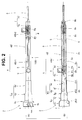
Fig. 2 is a view illustrating the configuration of the sheath for an endoscope; -
Fig. 3 is a view illustrating a procedure for mounting the sheath for an endoscope onto the endoscope; -
Fig. 4 is a view illustrating a state in which the sheath for an endoscope is mounted on the endoscope; -
Fig. 5 is a view illustrating an action of a stopper member, which is a view that illustrates a state in which a distal end face of a sheath body is disposed inside a region of a distal end portion, and a state in which the distal end portion is disposed inside the sheath body; -
Fig. 6 is a view illustrating another configuration example of a second knob portion and a stopper member; and -
Fig. 7 is a view illustrating the configuration of a sheath for an endoscope that includes two stopper members. - Preferred embodiments of the present invention are described hereunder with reference to the accompanying drawings.
- Note that the respective components in the respective drawings used for the following description are displayed in a different contraction scale so as to be shown in a size that is recognizable in the drawings. Further, the present invention is not limited only to the quantity of components, the shapes of components, the ratios between the sizes of components, and the relative positional relationship between the respective components illustrated in the drawings.
- An
endoscope apparatus 1 shown inFig. 1 includes a sheath for anendoscope 2 and anendoscope 10. - The
endoscope 10 is, for example, a nephroscope that is mainly constituted by aninsertion portion 11, anoperation portion 12 and anocular portion 13. Theocular portion 13 is provided on a proximal end side of theoperation portion 12. -
Reference numeral 14 denotes a light guide. Aconnection connector 14c of thelight guide 14 is detachably attached to a light guide connection port (not shown) that is provided at a side portion of theoperation portion 12. - The
insertion portion 11 includes, in order from the distal end side, a rigiddistal end portion 15, abending portion 16 that is configured to bend in the upward and downward directions, and aflexible tube portion 17 that is a tube body that is flexible which are connected in series. - A
bend preventing portion 18 having a previously determined elastic force is provided on a proximal end side of theflexible tube portion 17. Thebend preventing portion 18 is provided so as to cover the proximal end portion of theflexible tube portion 17 and prevent buckling of theflexible tube portion 17, and also is fixedly installed to maintain watertightness between theflexible tube portion 17 and the distal end side of theoperation portion 12. - A water leakage
detection pipe sleeve 19, a treatmentinstrument insertion port 20 and abending operation lever 21 and the like are provided in theoperation portion 12. Thebending operation lever 21 is rotatable. Thebending portion 16 bends in the two directions of upward and downward when bending wires (not shown) are pulled or slackened accompanying a rotational operation of thelever 21. - An observation window, an illuminating window and a treatment instrument opening, which are not shown in the drawings, are provided in a distal end face of the
distal end portion 15 of theinsertion portion 11. A bundle for illumination, a bundle for observation, a tube for a treatment instrument channel, an upward bending wire, a downward bending wire and the like, which are not shown in the drawings, are inserted through the inside of theinsertion portion 11. The bundle for illumination is a component for transmitting illuminating light to the illuminating window. The bundle for observation is a component for transmitting an observation image that is to be observed through the observation window. The tube for a treatment instrument channel links the treatment instrument opening and the treatmentinstrument insertion port 20 to constitute a treatment instrument channel. - Note that
reference numeral 22 denotes a passive bending portion that is configured to easily bend upon receiving an external force. Theendoscope 10 is not limited to a nephroscope, and may be any endoscope having a flexible insertion portion in which theinsertion portion 11 includes thebending portion 16 and theflexible tube portion 17. - The sheath for an
endoscope 2 is mainly constituted by asheath body 3 and anendoscope mounting portion 4. Thesheath body 3 is a rigid metal member made of, for example, stainless steel.Reference numeral 5 denotes a knob portion. Theknob portion 5 is fixedly installed in an integrated manner on thecontact member 6.Reference numeral 7 denotes a fixing member that is a second knob portion in the present embodiment. The fixingmember 7 is freely attachable to and detachable from astopper member 8. - The configuration of the sheath for an
endoscope 2 will now be described referring to (A) and (B) inFig. 2 . InFig. 2, (A) is a front view that includes a partial cross-sectional view, and (B) is an explanatory view that includes a cross-sectional view when the sheath for an endoscope shown in (A) is seen from the direction of an arrow Y2B. - As shown in (A) in
Fig. 2 , thesheath body 3 is a first tubular member. Thesheath body 3 is a so-called "pipe member" in which the diameter and inner diameter are constant, and which has a longitudinal axis direction through-hole that is a straight hole. The straight hole of thesheath body 3 is an insertionportion inserting hole 3h. Theinsertion portion 11 of theendoscope 10 can be disposed in an insertable/extractable manner in the insertionportion inserting hole 3h. - The
endoscope mounting portion 4 is a second tubular member. Theendoscope mounting portion 4 has a longitudinal axis direction through-hole 4h that has a stepped shape. In the present embodiment, theendoscope mounting portion 4 is constituted by integrally fixing together a mainbody pipe portion 4A and a sheath length adjustment pipe portion (hereunder, abbreviated as "sheath length adjustment portion") 4B by adhesion or bonding. - Note that the
endoscope mounting portion 4 is not limited to a configuration in which a plurality of members are fixed in an integrated manner, and may be constituted by a single pipe member. - The main
body pipe portion 4A is constituted by an operationportion arrangement portion 4c, a bend preventingarrangement portion 4d and a connectingportion 4e. - The connecting
portion 4e includes afitting hole 4f on an opening side. One end portion of the sheathlength adjustment portion 4B that has a straight pipe shape is fitted and disposed inside thefitting hole 4f, and is integrally fixed therein by, for example, adhesion. An inner face of the fixed sheathlength adjustment portion 4B and an inner face of the connectingportion 4e form substantially the same plane. The inner faces formed on the same plane serve as an inner face of a small-diameter straight hole 4h1 of the longitudinal axis direction through-hole 4h. - The bend preventing
arrangement portion 4d is constituted by a taperedface portion 4g and a bend preventingcontact portion 4i. The bend preventingcontact portion 4i is an intersecting portion between an inner face of the taperedface portion 4g and an inner face of the connectingportion 4e. In a state in which the sheath for anendoscope 2 is arranged on theendoscope 10, the bend preventingcontact portion 4i is pressingly disposed against thebend preventing portion 18. - Note that a taper angle of the tapered
face portion 4g is previously set to be greater than a taper angle of thebend preventing portion 18. Further, the inner diameter of the inner face of the connectingportion 4e is set to a diametrical dimension at a previously determined intermediate portion of thebend preventing portion 18. - The operation
portion arrangement portion 4c is constituted by a bend preventingcovering portion 4j and a pipesleeve arrangement portion 4k. The bend preventingcovering portion 4j and one part of the taperedface portion 4g cover the circumference of thebend preventing portion 18. The pipesleeve arrangement portion 4k covers the area around the vicinity of the water leakagedetection pipe sleeve 19 of theoperation portion 12. Anengagement grove 4m that constitutes a locking portion is provided in the pipesleeve arrangement portion 4k. A mirror image of the shape of theengagement grove 4m is an approximately "L" shape. Theengagement grove 4m is engagingly disposed on a shaft portion (denoted byreference character 19a inFig. 4 ) of the water leakagedetection pipe sleeve 19. - The longitudinal axis direction through-
hole 4h is mainly constituted by a small-diameter straight hole 4h1, a bend preventing covering hole 4h2 and an operation portion covering hole 4h3. - A through-hole of the sheath
length adjustment portion 4B is the small-diameter straight hole 4h1. Thecontact member 6 andstopper member 8 are slidably disposed in the small-diameter straight hole 4h1. - As shown in (A) and (B) in
Fig. 2 , a movement range setting hole 4Bh1 and a positioning hole 4Bh2 are formed in the outer circumferential face of the sheathlength adjustment portion 4B. - The movement range setting hole 4Bh1 is a long hole along a longitudinal axis a. The movement range setting hole 4Bh1 leads to the small-diameter straight hole 4h1 of the longitudinal axis direction through-
hole 4h. The movement range setting hole 4Bh1 sets a movement range in the longitudinal axis direction of thecontact member 6. - The positioning hole 4Bh2 is a through-hole that leads to the small-diameter straight hole 4h1. In the present embodiment, the positioning hole 4Bh2 is a long hole along the longitudinal axis a. The positioning hole 4Bh2 sets a movement range in the longitudinal axis direction of the
stopper member 8. - One end of the movement range setting hole 4Bh1 is formed at a position that is separated by a previously determined distance from one end face of the
endoscope mounting portion 4. The other end of the movement range setting hole 4Bh1 is formed at a position that is separated by a previously determined distance from the one end of the setting hole 4Bh1. - One end of the positioning hole 4Bh2 is formed at a position that is separated by a previously determined distance from the other end of the movement range setting hole 4Bh1. The other end of the positioning hole 4Bh2 is formed at a position that is separated by a previously determined distance from the one end of the positioning hole 4Bh2. The positioning hole 4Bh2 is provided at a position on the other end face side of the
endoscope mounting portion 4. - The
contact member 6 is a cylindrical shape and is slidably disposed in the small-diameter straight hole 4h1. Thecontact member 6 includes an axial direction through-hole 6h and afemale thread portion 6d. - An axial
direction hole portion 6a and an introducing hole portion are provided in the axial direction through-hole 6h. - The introducing
hole portion 6b has an opening in one end face side that is a hole provided with atapered face 6c. The taperedface 6c is a guide face for smoothly guiding thedistal end portion 15 of theinsertion portion 11 into the insertionportion inserting hole 3h of thesheath body 3. The diametrical dimension of the taperedface 6c is such that the diameter continuously decreases as the distance from the opening increases. - The axial
direction hole portion 6a is a straight hole that has an opening in the other end face side. One end portion of thesheath body 3 is arranged in the axialdirection hole portion 6a. A bottom face of the introducinghole portion 6b and a bottom face of the axialdirection hole portion 6a communicate by means of a connection hole (not shown in the drawings). The diametrical dimension of the connection hole is set to approximately the same dimension as the diametrical dimension of the insertionportion inserting hole 3h. - The one end portion of the
sheath body 3 is integrally fixed by, for example, adhesion to the axialdirection hole portion 6a. As a result, thesheath body 3 is provided in a protruding condition from the other end face side of thecontact member 6. In the fixedly installed state, the insertionportion inserting hole 3h of thesheath body 3 and the introducinghole portion 6b are linked by a communicating hole. - The
female thread portion 6d is made by forming a female thread in an inner face of a concave portion provided in a side face of thecontact member 6. An axis of the concave portion is orthogonal to an axis of the axial direction through-hole 6h. - A
male thread portion 5a that is provided on theknob portion 5 is threadedly disposed in thefemale thread portion 6d. Themale thread portion 5a is inserted through the inside of the movement range setting hole 4Bh1 formed in theendoscope mounting portion 4 and is threadedly engaged with thefemale thread portion 6d. Theknob portion 5 is disposed integrally in thecontact member 6 in a state in which theendoscope mounting portion 4 is interposed therebetween. - The
contact member 6 is fixed integrally to theendoscope mounting portion 4 by adjusting the threadedly engaged state by pressingly disposing apressing face 5b of theknob portion 5 against the external surface of theendoscope mounting portion 4. In contrast thereto, thecontact member 6 is arranged so as to freely advance and retreat in the direction of the longitudinal axis a of theendoscope mounting portion 4 inside the small-diameter straight hole 4h1 by adjusting the threadedly engaged state so as to provide a gap between thepressing face 5b of theknob portion 5 and the external surface of theendoscope mounting portion 4. - The distal end face of the
sheath body 3 comes closest to the distal end face of theendoscope mounting portion 4 when theknob portion 5 is moved inside the movement range setting hole 4Bh1 to cause theknob portion 5 to abut against one end thereof. On the other hand, the distal end face of thesheath body 3 is furthest from the distal end face of theendoscope mounting portion 4 at a time that theknob portion 5 is caused to abut against the other end. - The
stopper member 8 is a cylindrical shape and is slidably disposed in the small-diameter straight hole 4h1. Thestopper member 8 includes a holdinghole 8h that is an axial direction through-hole and afemale thread portion 8a. - The holding
hole 8h is a through-hole that holds thesheath body 3 in a manner such that thesheath body 3 is capable of advancing and retreating. Thesheath body 3 that protrudes from the other end face side of thecontact member 6 is inserted through the holdinghole 8h. - One end face of the
stopper member 8 is a contact portion that acontact face 6e that is the other end face of thecontact member 6 contacts against. - The
female thread portion 8a is made by forming a female thread in an inner face of a concave portion provided in a side face of thestopper member 8. An axis of the concave portion is orthogonal to an axis of the holdinghole 8h. An opening of thefemale thread portion 8a opens in a direction orthogonal to the axis of the holdinghole 8h. - A
male thread portion 7a that is provided on asecond knob portion 7 that is a positioning and fixing member is threadedly disposed in thefemale thread portion 8a. Themale thread portion 7a is inserted through the inside of the positioning hole 4Bh2 that is a long hole formed in theendoscope mounting portion 4, and is threadedly engaged with thefemale thread portion 8a. Thesecond knob portion 7 is disposed integrally in thestopper member 8 in a state in which theendoscope mounting member 4 is interposed therebetween. - The
stopper member 8 is fixed integrally to theendoscope mounting portion 4 by adjusting the threadedly engaged state by pressingly disposing apressing face 7b of thesecond knob portion 7 against the external surface of theendoscope mounting portion 4. In contrast thereto, thestopper member 8 is arranged so as to freely advance and retreat in the direction of the longitudinal axis a of theendoscope mounting portion 4 inside the small-diameter straight hole 8h1 by adjusting the threadedly engaged state so as to provide a gap between thepressing face 7b of thesecond knob portion 7 and the external surface of theendoscope mounting portion 4. - A position that the
contact face 6e of thecontact member 6 contacts against is changed by moving thestopper member 8 inside the positioning hole 4Bh2. That is, a distance between the distal end face of theendoscope mounting portion 4 and the distal end face of thesheath body 3 is adjusted by adjusting the position at which thestopper member 8 is disposed. - In the present embodiment, an O-shaped
ring 8b that is an urging member is arranged inside the holdinghole 8h on the other end face side of thestopper member 8. The O-shapedring 8b is a sliding resistance member, and imparts a desired sliding resistance to thesheath body 3. Accordingly, the O-shapedring 8b closely contacts the external surface of thesheath body 3 that is inserted through the inside of the holdinghole 8h, in a state in which the O-shapedring 8b is deformed by a previously determined amount. - In a state in which sliding resistance is imparted to the
sheath body 3 from the O-shapedring 8b, thesheath body 3 is prevented from moving under its own weight with respect to theendoscope mounting portion 4, even if the state is one in which thecontact member 6 disposed in the small-diameter straight hole 4h1 can advance/retreat in the direction of the longitudinal axis a of theendoscope mounting portion 4. -
Reference character 8c denotes a tapered face. The taperedface 8c is provided on one end face side of the holdinghole 8h. Similarly to the taperedface 6c, the taperedface 8c is constituted so that the diametrical dimension continuously decreases as the distance from the opening increases. - The tapered
face 8c of the holdinghole 8h is a guide face for smoothly guiding an end portion of thesheath body 3 into the holdinghole 8h. - The action of the sheath for an
endoscope 2 configured as described above will now be described. - The
endoscope 10 for performing an observation or the like inside a kidney, and the sheath for anendoscope 2 are prepared. A physician or a medical worker mounts the sheath for anendoscope 2 on theendoscope 10 in advance. - At such time, the medical worker (hereunder, referred to as "operator") moves the
stopper member 8 to the most distal end side as shown in (A) inFig. 2 , and thereafter pressingly disposes thepressing face 7b of thesecond knob portion 7 against the external surface of theendoscope mounting portion 4. Further, as shown by a dashed line in (B) inFig. 2 , the operator causes thecontact face 6e of thecontact member 6 to contact against the contact portion of thestopper member 8, and thereafter pressingly disposes thepressing face 5b of theknob portion 5 against the external surface of theendoscope mounting portion 4. - Thereafter, the operator inserts the
distal end portion 15 of theinsertion portion 11 of theendoscope 10 towards the inside of the insertionportion inserting hole 3h of thesheath body 3 through the operation portion covering hole 4h3 that has an opening on the proximal end side of the sheath for anendoscope 2. Thereupon, as shown in (A) inFig. 3 , the operationportion arrangement portion 4c of the mainbody pipe portion 4A included in the sheath for anendoscope 2 approaches the water leakagedetection pipe sleeve 19 that is provided in theoperation portion 12. - In this case, as shown in (B) in
Fig. 3 , the operator brings the mainbody pipe portion 4A close to the water leakagedetection pipe sleeve 19 while performing a positional adjustment so that the opening of theengagement grove 4m is engagingly disposed at the water leakagedetection pipe sleeve 19. Thereupon, the bend preventingcontact portion 4i of the mainbody pipe portion 4A contacts against thebend preventing portion 18 of theendoscope 10. - Next, the operator moves the main
body pipe portion 4A further against the elastic force of thebend preventing portion 18 and, as shown in (C) ofFig. 3 , moves the mainbody pipe portion 4A by pushing in the mainbody pipe portion 4A so that the water leakagedetection pipe sleeve 19 is disposed inside theengagement grove 4m. At this time, thebend preventing portion 18 gradually undergoes elastic deformation accompanying movement of the mainbody pipe portion 4A. - Next, the operator subjects the main
body pipe portion 4A to a twisting operation to, as shown in (D) ofFig. 3 , dispose the water leakagedetection pipe sleeve 19 inside a deep part of the groove which is a part that is separated from the opening of theengagement grove 4m. Thus, as shown in (D) inFig. 3 and inFig. 4 , theengagement grove 4m is engagingly disposed around ashaft portion 19a of the water leakagedetection pipe sleeve 19 and mounting of the sheath for anendoscope 2 to theendoscope 10 is completed. - At this time, the
engagement grove 4m is in a state of being urged to the distal end side of theinsertion portion 11 at all times by the elastic force of thebend preventing portion 18. As a result, theengagement grove 4m is reliably and stably fixed on theshaft portion 19a. - Note that, in the present embodiment, the bend preventing
covering portion 4j and the pipesleeve arrangement portion 4k are provided in the operationportion arrangement portion 4c, and theengagement grove 4m is provided in the pipesleeve arrangement portion 4k. Further, theengagement grove 4m is engagingly disposed on theshaft portion 19a of the water leakagedetection pipe sleeve 19 to perform mounting of the sheath for anendoscope 2 onto theendoscope 10. - However, mounting of the sheath for an
endoscope 2 to theendoscope 10 is not limited to engagement of theengagement grove 4m onto theshaft portion 19a of the water leakagedetection pipe sleeve 19, and as long as theengagement grove 4m is engaged with a convex portion that protrudes from theoperation portion 12, mounting of the sheath for anendoscope 2 may be performed to a pipe sleeve other than the water leakagedetection pipe sleeve 19 or to a pipe sleeve or the like constituting the treatmentinstrument insertion port 20. - For example, in a case where the engagement grove is engaged with a shaft portion of a pipe sleeve of the treatment
instrument insertion port 20, a configuration may be adopted in which the bend preventingcovering portion 4j and an insertion pipe sleeve arrangement portion are provided on the operationportion arrangement portion 4c, and an engagement grove is provided in the insertion pipe sleeve arrangement portion to enable mounting of the sheath for anendoscope 2 to theendoscope 10. - Next, the operator checks whether or not the distal end face of the
sheath body 3 included in the sheath for anendoscope 2 is disposed at a previously determined position on the outer circumferential face of thedistal end portion 15 of theinsertion portion 11. - In this case, as shown in (A) in
Fig. 5 , if the distal end face of thesheath body 3 is disposed inside a previouslydetermined region 15A on the outer circumferential face of thedistal end portion 15, the operator ends the mounting operation. In contrast, as shown in (B) inFig. 5 , if thedistal end portion 15 is disposed inside thesheath body 3, the operator moves thestopper member 8 rearward in the direction of the bendingportion 16 of theinsertion portion 11. - At this time, the operator adjusts the threadedly engaged state of the
knob portion 5 so as to provide a gap between thepressing face 5b and the external surface of theendoscope mounting portion 4, and adjusts the threadedly engaged state of thesecond knob portion 7 so as to provide a gap between thepressing face 7b and the external surface of theendoscope mounting portion 4. Thereafter, the operator moves thesecond knob portion 7 in the arrow direction that is indicated by a dashed line to gradually retract thestopper member 8. The operator then adjusts the disposing positions so that the distal end face of thesheath body 3 is positioned inside the previouslydetermined region 15A on the outer circumferential face of thedistal end portion 15. - After adjusting the disposing positions, the operator adjusts the threadedly engaged state of the
knob portion 5 and the threadedly engaged state of thesecond knob portion 7, respectively, and pressingly disposes thepressing face 5b against the external surface of theendoscope mounting portion 4 and also pressingly disposes thepressing face 7b against the external surface of theendoscope mounting portion 4 to thereby complete the mounting work. - Finally, the operator adjusts the threadedly engaged state of the
knob portion 5 so as to enter a state in which a gap is provided between thepressing face 5b and the external surface of theendoscope mounting portion 4. The operator then moves thecontact member 6 in a retreating direction and checks whether or not the bendingportion 16 and thepassive bending portion 22 are completely exposed. Further, in a case where the bendingportion 16 and thepassive bending portion 22 are completely exposed before theknob portion 5 arrives at one end of the movement range setting hole 4Bh1, the operator attaches, for example, a notification seal for notifying the physician of the relevant position to the external surface of the sheathlength adjustment portion 4B. - Subsequently, after checking whether or not the bending
portion 16 is completely exposed, the operator again places thecontact face 6e of thecontact member 6 in a state in which thecontact face 6e contacts against the contact portion of thestopper member 8. Thereafter, the operator pressingly disposes thepressing face 5b of theknob portion 5 against the external surface of theendoscope mounting portion 4 to thereby complete the mounting work. - Subsequently, to perform an observation inside a kidney, the physician inserts the
insertion portion 11 of theendoscope 10 on which thesheath body 3 of the sheath for anendoscope 2 is mounted into the urinary duct, and introduces theinsertion portion 11 towards the inside of the kidney. At this time, because theflexible insertion portion 11 is being covered and made rigid by thesheath body 3, thedistal end portion 15 of theinsertion portion 11 is smoothly introduced into the kidney. - Upon confirming through the
ocular portion 13 that thedistal end portion 15 is introduced into the kidney, the physician adjusts the threadedly engaged state of theknob portion 5 to enter a state in which a gap is provided between thepressing face 5b and the external surface of theendoscope mounting portion 4. At this time, the physician moves thecontact member 6 in a retreating direction to enter a state in which the bendingportion 16 and thepassive bending portion 22 are completely exposed. - Thereafter, the physician appropriately operates the bending
operation lever 21 to cause the bendingportion 16 to perform a bending operation and carries out observation or treatment inside the kidney. After completing the observation or treatment, the physician extracts theinsertion portion 11 of theendoscope 10 on which the sheath for anendoscope 2 is mounted from inside the urinary duct to thereby end the endoscopic procedure. - Thus, the
sheath body 3 that covers theflexible insertion portion 11 of theendoscope 10 is configured to be capable of advancing/retreating by a previously determined distance with respect to theendoscope mounting portion 4 constituting the sheath for anendoscope 2. - According to this configuration, by covering the
flexible insertion portion 11 with thesheath body 3, theinsertion portion 11 can be smoothly introduced into a kidney via the urinary duct, for example. - Further, after being introduced into the kidney, the physician moves the
sheath body 3 by a previously determined distance with respect to theendoscope mounting portion 4 to expose the bendingportion 16 that is provided in theinsertion portion 11. By this means, the physician can cause the bendingportion 16 to perform a bending operation and can observe the inside of the kidney over a wide range. - Further, in addition to having a configuration such that the
sheath body 3 is capable of advancing/retreating by a previously determined distance in the longitudinal axis direction of theendoscope mounting portion 4, thestopper member 8 for changing the disposing position of the distal end of thesheath body 3 is configured to move forward/rearward by a previously determined distance in the longitudinal axis direction of theendoscope mounting portion 4. - According to this configuration, even in a case where there is a difference in length due to an individual difference in the
insertion portion 11 of theendoscope 10 that is combined with the sheath for anendoscope 2, by adjusting the disposing position of thestopper member 8 it is possible to reliably dispose the distal end face of thesheath body 3 constituting the sheath for anendoscope 2 inside the previouslydetermined region 15A on the outer circumferential face of thedistal end portion 15 of theinsertion portion 11. - Further, the O-shaped
ring 8b that imparts sliding resistance to thesheath body 3 is provided inside the holdinghole 8h of thestopper member 8 and closely contacts the external surface of thesheath body 3 that is inserted through the inside of the holdinghole 8h. By this means, even in a state in which thecontact member 6 can freely advance/retreat in the direction of the longitudinal axis a of theendoscope mounting portion 4, thesheath body 3 can be prevented from moving under its own weight with respect to theendoscope mounting portion 4. - Note that, in the above-described embodiment, a configuration is adopted in which the disposing position of the
stopper member 8 can be adjusted by moving thesecond knob portion 7 along the positioning hole 4Bh2 that is a long hole. However, instead of the positioning hole 4Bh2, a configuration may also be adopted in which a plurality of positioning holes 4Bh3 constituted by a plurality of, for example, round holes that are through-holes that lead to the small-diameter straight hole 4h1 are arranged in the longitudinal axis direction as shown in (A) ofFig. 6 . - According to this configuration, when changing the position of the
stopper member 8, as indicated by dashed lines, thesecond knob portion 7 is taken out once from thestopper member 8, the operator then moves thestopper member 8, and thereafter threadedly engages thesecond knob portion 7 with thestopper member 8 again. As a result, adjustment of the disposing position of thestopper member 8 can be performed. - In the above-described embodiment, the fixing member is configured as the second knob portion having a male thread portion. However, the fixing member is not limited to a knob portion having a male thread portion. For example, as shown in (B) in
Fig. 6 , the fixing member may be a lockingpin 7D in which apin portion 7c protrudes from a distal end of a knob or the like. In a configuration that uses thelocking pin 7D instead of the second knob portion, anengagement hole 8d is provided instead of thefemale thread 8a in thestopper member 8. - According to this configuration, when changing the position of the
stopper member 8, thepin portion 7c of thelocking pin 7D is engagedly inserted into theengagement hole 8d through a desired positioning hole 4Bh3. As a result, adjustment of the disposing position of thestopper member 8 can be performed. - In addition, in the above-described embodiment, the distance by which the distal end face of the
sheath body 3 is separated from the distal end face of theendoscope mounting portion 4 is adjusted by adjusting the disposing position of thestopper member 8 provided on the distal end side of the sheathlength adjustment portion 4B. However, as shown in (A) and (B) inFig. 7 , a configuration may also be adopted in which asecond stopper member 8A is provided in addition to thestopper member 8 to enable adjustment of the distance by which the distal end face of thesheath body 3 is separated from the distal end face of theendoscope mounting portion 4. - Note that the
second stopper member 8A has the same configuration as that of thestopper member 8. Further, in a sheath for anendoscope 2A in which thesecond stopper member 8A is provided, a second positioning hole 4Bh4 that is a long hole along the longitudinal axis a that leads to the small-diameter straight hole 4h1 is provided on the proximal end side of the sheathlength adjustment portion 4B in addition to the positioning hole 4Bh2. Note that the positioning hole 4Bh4 sets the movement range of thesecond stopper member 8A in the longitudinal axis direction. - According to this configuration, after the operator performs adjustment of the disposing position by gradually retracting the above-described
stopper member 8 so that the distal end face of thesheath body 3 is positioned inside the previouslydetermined region 15A on the outer circumferential face of thedistal end portion 15, if the bendingportion 16 and thepassive bending portion 22 are completely exposed before theknob portion 5 reaches one end of the movement range setting hole 4Bh1, the operator disposes and fixes thesecond stopper member 8A at the relevant position instead of attaching a notification seal to the external surface of the sheathlength adjustment portion 4B. - As a result, when the physician causes the
contact member 6 to move rearward after confirming through theocular portion 13 that thedistal end portion 15 is introduced into the kidney, without viewing a notification seal the physician can place the bendingportion 16 and thepassive bending portion 22 in a completely exposed state by bringing the contact face of the proximal end side of thecontact member 6 into contact with the contact portion on the distal end side of thesecond stopper member 8A. - Note that in a case where, for example, there is a request from the physician to dispose the distal end face of the
sheath body 3 at a portion that is partway along thepassive bending portion 22 to perform fine adjustment of the bending function, the operator disposes and fixes thesecond stopper member 8A in accordance with the request of the physician. - Thus, the
second stopper member 8A is provided in addition to thestopper member 8 on the sheath for anendoscope 2A. By this means, if there is an individual difference in the length or the like of the bendingportion 16 or the length or the like of thepassive bending portion 22 in addition to a difference in length that is caused by an individual difference of theinsertion portion 11 of theendoscope 10, by adjusting the disposing position of thesecond stopper member 8A, an adjustment that corresponds to a request of the physician can be easily performed, such as reliably exposing the bendingportion 16 and thepassive bending portion 22. - Note that, in the above described configuration, the positioning hole 4Bh4 that differs with the positioning hole 4Bh2 is provided in the main
body pipe portion 4A. However, a configuration may also be adopted in which the positioning hole 4Bh2 and the positioning hole 4Bh4 are configured as a dual-purpose positioning hole that is constituted by a single long hole that is formed in a straight line. - Further, the positioning hole 4Bh4 may be constituted by a plurality of through-holes similarly to the positioning hole 4Bh2.
- It should be understood that the present invention is not limited only to the above described embodiments, and various modifications can be made without departing from the spirit and scope of the invention.
- The present application claims priority from Japanese Patent Application No.
2013-265324
Claims (10)
- A sheath for an endoscope, comprising:a first tubular member having a longitudinal axis direction through-hole in which an insertion portion of an endoscope that has a distal end portion, a bending portion and a flexible tube portion can be disposed in an insertable/extractable manner;a stopper member that has a holding hole that holds the first tubular member so that the first tubular member is capable of advancing and retreating, and a concave portion forming an opening in a direction perpendicular to an axis of the holding hole;a contact member that is integrally fixed to one end portion side of the first tubular member which is held so as to be capable of advancing and retreating inside the holding hole of the stopper member and which protrudes from one end face side of the stopper member, and that has a contact face that contacts against one end face of the stopper member;a second tubular member that includes a longitudinal axis direction through-hole in which the contact member and the stopper member can be slidably disposed, a locking portion that is provided on a one end-face opening side of the longitudinal axis direction through-hole and that can be locked to an operation portion of the endoscope, a movement range setting hole that is a long hole leading to the longitudinal axis direction through-hole and that sets a longitudinal axis direction movement range of the contact member with which the first tubular member is integrated, and a positioning hole that is a through-hole leading to the longitudinal axis direction through-hole and that is formed so as to be alignable with respect to the concave portion of the stopper member that is provided on the other end-face opening side of the longitudinal axis direction through-hole;a positioning and fixing member that is disposed in the concave portion of the stopper member through the positioning hole that the second tubular member includes, and that positions and fixes the stopper member with respect to the second tubular member; anda knob portion that is integrally fixed to the contact member through the movement range setting hole that the second tubular member includes.
- The sheath for an endoscope according to claim 1, wherein the positioning hole is an elongated long hole along a longitudinal axis direction of the second tubular member or is a plurality of through-holes provided in the longitudinal axis direction.
- The sheath for an endoscope according to claim 2, wherein the concave portion of the stopper member is a threaded portion having a female thread, and the positioning and fixing member has a male thread that is threadedly disposed in the female thread of the threaded portion through the long hole or a through-hole.
- The sheath for an endoscope according to claim 2, wherein the concave portion of the stopper member is an engagement hole, and the positioning and fixing member has a pin portion that is engagedly inserted into the engagement hole through the through-hole.
- The sheath for an endoscope according to claim 1, further comprising an urging member that closely contacts an external surface of the first tubular member inside the holding hole provided in the stopper member and imparts sliding resistance to the first tubular member.
- The sheath for an endoscope according to claim 1, wherein:in a configuration in which a first stopper member for adjusting a disposing position of a distal end face of the first tubular member on the distal end portion of the endoscope, and a second stopper member for adjusting the disposing position of the distal end face of the first tubular member to a position at which the bending portion of the endoscope is in a desired exposed state are provided in the longitudinal axis direction through-hole of the second tubular member,in the second tubular member, a positioning hole is provided for disposing a positioning and fixing member for positioning and fixing each of the stopper members with respect to the second tubular member in a concave portion of the stopper member.
- The sheath for an endoscope according to claim 6, comprising, in the second tubular member, a first positioning hole for disposing a first fixing member in the concave portion of the first stopper member, and a second positioning hole for disposing a second fixing member in the concave portion of the second stopper member.
- The sheath for an endoscope according to claim 7, wherein a dual-purpose positioning hole that is used as both the first positioning hole and the second positioning hole is provided in the second tubular member.
- The sheath for an endoscope according to any one of claims 1 to 8, wherein a sliding resistance member is provided between the holding hole of the stopper member and the first tubular member.
- The sheath for an endoscope according to claim 9, wherein the sliding resistance member is an O-shaped ring.
Applications Claiming Priority (2)
| Application Number | Priority Date | Filing Date | Title |
|---|---|---|---|
| JP2013265324 | 2013-12-24 | ||
| PCT/JP2014/074906 WO2015098210A1 (en) | 2013-12-24 | 2014-09-19 | Endoscope sheath |
Publications (2)
| Publication Number | Publication Date |
|---|---|
| EP2989960A1 true EP2989960A1 (en) | 2016-03-02 |
| EP2989960A4 EP2989960A4 (en) | 2016-12-28 |
Family
ID=53478092
Family Applications (1)
| Application Number | Title | Priority Date | Filing Date |
|---|---|---|---|
| EP14873687.9A Withdrawn EP2989960A4 (en) | 2013-12-24 | 2014-09-19 | Endoscope sheath |
Country Status (5)
| Country | Link |
|---|---|
| US (1) | US20160073861A1 (en) |
| EP (1) | EP2989960A4 (en) |
| JP (1) | JP5802864B1 (en) |
| CN (1) | CN105246392B (en) |
| WO (1) | WO2015098210A1 (en) |
Families Citing this family (9)
| Publication number | Priority date | Publication date | Assignee | Title |
|---|---|---|---|---|
| CN108601507B (en) * | 2016-01-29 | 2021-11-26 | 波士顿科学医学有限公司 | Accessory for imaging equipment |
| JPWO2017212725A1 (en) * | 2016-06-07 | 2018-06-28 | オリンパス株式会社 | Medical observation system |
| EP3599983B1 (en) | 2017-03-24 | 2023-11-15 | Covidien LP | Endoscopes |
| CN106923778B (en) * | 2017-04-25 | 2018-09-18 | 湖北迪奥医疗科技有限公司 | A kind of disposable hard endoscope casing tube camera lens and alignment lens method |
| WO2019125581A1 (en) * | 2017-12-19 | 2019-06-27 | Intuitive Surgical Operations, Inc. | Imaging systems and methods of use |
| JP2021119800A (en) * | 2018-03-19 | 2021-08-19 | オリンパス株式会社 | Insertion aid for endoscope and endoscope system |
| ES2870373T3 (en) * | 2018-05-18 | 2021-10-26 | Verathon Inc | Endoscope system with a control wheel assembly attached to traction cables |
| CN110367907B (en) | 2019-08-07 | 2024-04-12 | 湖南省华芯医疗器械有限公司 | Hand-held end of endoscope |
| CN117860178A (en) * | 2023-12-25 | 2024-04-12 | 珠海普生医疗科技有限公司 | Medical device with integrated outer sheath |
Family Cites Families (13)
| Publication number | Priority date | Publication date | Assignee | Title |
|---|---|---|---|---|
| DE3704247A1 (en) * | 1986-02-14 | 1987-08-20 | Olympus Optical Co | ENDOSCOPE INSERTION DEVICE |
| US8858576B2 (en) * | 2007-09-10 | 2014-10-14 | Olympus Medical Systems Corp. | Tissue fastening tool, stent, applicator for placing the same, and tissue fastening method through natural orifice |
| US20090287044A1 (en) * | 2008-05-15 | 2009-11-19 | Olympus Medical Systems Corp. | Endoscopic apparatus |
| ES2700863T3 (en) * | 2008-07-30 | 2019-02-19 | Acclarent Inc | Devices for localization of the paranasal ostium |
| US9332973B2 (en) * | 2008-10-01 | 2016-05-10 | Covidien Lp | Needle biopsy device with exchangeable needle and integrated needle protection |
| JP2010253150A (en) | 2009-04-28 | 2010-11-11 | Hoya Corp | Sheath device for endoscope |
| US8282667B2 (en) * | 2009-06-05 | 2012-10-09 | Entellus Medical, Inc. | Sinus dilation catheter |
| US8834513B2 (en) * | 2009-06-05 | 2014-09-16 | Entellus Medical, Inc. | Method and articles for treating the sinus system |
| WO2012033760A1 (en) * | 2010-09-07 | 2012-03-15 | Boston Scientific Scimed, Inc. | Endoscopic ultrasound fine needle aspiration device |
| EP2618719B1 (en) * | 2010-09-22 | 2017-10-04 | Acclarent, Inc. | Apparatus for treating disorders of the sinuses |
| KR102003685B1 (en) * | 2010-09-22 | 2019-07-26 | 아클라런트, 인코포레이션 | Medical device for treatment of a sinus opening |
| US9486614B2 (en) * | 2011-06-29 | 2016-11-08 | Entellus Medical, Inc. | Sinus dilation catheter |
| US9439674B2 (en) * | 2013-07-25 | 2016-09-13 | Cardiovascular Systems, Inc. | Rotational atherectomy device with exchangeable drive shaft and meshing gears |
-
2014
- 2014-09-19 JP JP2015511832A patent/JP5802864B1/en active Active
- 2014-09-19 EP EP14873687.9A patent/EP2989960A4/en not_active Withdrawn
- 2014-09-19 CN CN201480030445.2A patent/CN105246392B/en active Active
- 2014-09-19 WO PCT/JP2014/074906 patent/WO2015098210A1/en not_active Ceased
-
2015
- 2015-11-23 US US14/949,035 patent/US20160073861A1/en not_active Abandoned
Also Published As
| Publication number | Publication date |
|---|---|
| JPWO2015098210A1 (en) | 2017-03-23 |
| EP2989960A4 (en) | 2016-12-28 |
| US20160073861A1 (en) | 2016-03-17 |
| WO2015098210A1 (en) | 2015-07-02 |
| CN105246392B (en) | 2017-09-19 |
| CN105246392A (en) | 2016-01-13 |
| JP5802864B1 (en) | 2015-11-04 |
Similar Documents
| Publication | Publication Date | Title |
|---|---|---|
| EP2989960A1 (en) | Endoscope sheath | |
| EP3626154B1 (en) | Modular endoscope | |
| US8979739B2 (en) | Bending tube and medical instrument | |
| EP2030557A1 (en) | Endoscopie guiding tube device | |
| JP2009279411A (en) | Endoscopic apparatus | |
| JP5228161B2 (en) | Endoscope bending device | |
| EP3195788A1 (en) | Endoscope curved portion | |
| WO2016138439A1 (en) | Oblique tip endoscope with zero degree field angle | |
| JPWO2014038254A1 (en) | Endoscope | |
| AU2018241145B2 (en) | Connector device for gastric calibration hoses, as well as medical system comprising a connector device for gastric calibration hoses and a gastric calibration hose | |
| US20180256011A1 (en) | Endoscope adaptor, endoscope, and endoscope system | |
| JP2006204476A (en) | Endoscopic treatment tool | |
| CN205181288U (en) | Endoscopy system | |
| JP3034641B2 (en) | Endoscope | |
| JP5555019B2 (en) | Guide tube | |
| CN107405051B (en) | endoscope system | |
| WO2015163019A1 (en) | Insertion device | |
| JPH11244223A (en) | Endoscope treatment instrument insertion channel | |
| EP3490428B1 (en) | Steerable catheter handle | |
| JP2018189897A (en) | Endoscope-purpose guide tube | |
| JP2016214282A (en) | Endoscope device | |
| JP2005329078A (en) | Puncture needle device for endoscope | |
| JPH01287523A (en) | Endoscope insertion assistant | |
| JP4217246B2 (en) | Endoscope puller and endoscope | |
| CN119279801A (en) | Obturators and endoscopic surgical equipment |
Legal Events
| Date | Code | Title | Description |
|---|---|---|---|
| PUAI | Public reference made under article 153(3) epc to a published international application that has entered the european phase |
Free format text: ORIGINAL CODE: 0009012 |
|
| 17P | Request for examination filed |
Effective date: 20151123 |
|
| AK | Designated contracting states |
Kind code of ref document: A1 Designated state(s): AL AT BE BG CH CY CZ DE DK EE ES FI FR GB GR HR HU IE IS IT LI LT LU LV MC MK MT NL NO PL PT RO RS SE SI SK SM TR |
|
| AX | Request for extension of the european patent |
Extension state: BA ME |
|
| RAP1 | Party data changed (applicant data changed or rights of an application transferred) |
Owner name: OLYMPUS CORPORATION |
|
| RIN1 | Information on inventor provided before grant (corrected) |
Inventor name: KANEKO, HIROYUKI |
|
| A4 | Supplementary search report drawn up and despatched |
Effective date: 20161125 |
|
| RIC1 | Information provided on ipc code assigned before grant |
Ipc: G02B 23/24 20060101ALI20161121BHEP Ipc: A61B 1/00 20060101AFI20161121BHEP |
|
| DAX | Request for extension of the european patent (deleted) | ||
| STAA | Information on the status of an ep patent application or granted ep patent |
Free format text: STATUS: EXAMINATION IS IN PROGRESS |
|
| 17Q | First examination report despatched |
Effective date: 20171206 |
|
| STAA | Information on the status of an ep patent application or granted ep patent |
Free format text: STATUS: THE APPLICATION IS DEEMED TO BE WITHDRAWN |
|
| 18D | Application deemed to be withdrawn |
Effective date: 20181212 |