EP2989371B1 - Lever valve - Google Patents
Lever valve Download PDFInfo
- Publication number
- EP2989371B1 EP2989371B1 EP14725915.4A EP14725915A EP2989371B1 EP 2989371 B1 EP2989371 B1 EP 2989371B1 EP 14725915 A EP14725915 A EP 14725915A EP 2989371 B1 EP2989371 B1 EP 2989371B1
- Authority
- EP
- European Patent Office
- Prior art keywords
- lever
- visual display
- valve
- valve body
- closed position
- Prior art date
- Legal status (The legal status is an assumption and is not a legal conclusion. Google has not performed a legal analysis and makes no representation as to the accuracy of the status listed.)
- Active
Links
- 230000000007 visual effect Effects 0.000 claims description 31
- 230000001681 protective effect Effects 0.000 claims description 9
- 239000012780 transparent material Substances 0.000 claims description 3
- 229910001369 Brass Inorganic materials 0.000 description 3
- 239000010951 brass Substances 0.000 description 3
- 238000005266 casting Methods 0.000 description 3
- 238000012790 confirmation Methods 0.000 description 2
- 230000000712 assembly Effects 0.000 description 1
- 238000000429 assembly Methods 0.000 description 1
- 239000012530 fluid Substances 0.000 description 1
- 239000000463 material Substances 0.000 description 1
- 238000012544 monitoring process Methods 0.000 description 1
- 239000004033 plastic Substances 0.000 description 1
- 229920003023 plastic Polymers 0.000 description 1
- 229920003229 poly(methyl methacrylate) Polymers 0.000 description 1
- 239000004417 polycarbonate Substances 0.000 description 1
- 229920000515 polycarbonate Polymers 0.000 description 1
- 239000004926 polymethyl methacrylate Substances 0.000 description 1
Images

Classifications
-
- F—MECHANICAL ENGINEERING; LIGHTING; HEATING; WEAPONS; BLASTING
- F16—ENGINEERING ELEMENTS AND UNITS; GENERAL MEASURES FOR PRODUCING AND MAINTAINING EFFECTIVE FUNCTIONING OF MACHINES OR INSTALLATIONS; THERMAL INSULATION IN GENERAL
- F16K—VALVES; TAPS; COCKS; ACTUATING-FLOATS; DEVICES FOR VENTING OR AERATING
- F16K37/00—Special means in or on valves or other cut-off apparatus for indicating or recording operation thereof, or for enabling an alarm to be given
- F16K37/0008—Mechanical means
-
- F—MECHANICAL ENGINEERING; LIGHTING; HEATING; WEAPONS; BLASTING
- F17—STORING OR DISTRIBUTING GASES OR LIQUIDS
- F17C—VESSELS FOR CONTAINING OR STORING COMPRESSED, LIQUEFIED OR SOLIDIFIED GASES; FIXED-CAPACITY GAS-HOLDERS; FILLING VESSELS WITH, OR DISCHARGING FROM VESSELS, COMPRESSED, LIQUEFIED, OR SOLIDIFIED GASES
- F17C13/00—Details of vessels or of the filling or discharging of vessels
- F17C13/04—Arrangement or mounting of valves
-
- F—MECHANICAL ENGINEERING; LIGHTING; HEATING; WEAPONS; BLASTING
- F16—ENGINEERING ELEMENTS AND UNITS; GENERAL MEASURES FOR PRODUCING AND MAINTAINING EFFECTIVE FUNCTIONING OF MACHINES OR INSTALLATIONS; THERMAL INSULATION IN GENERAL
- F16K—VALVES; TAPS; COCKS; ACTUATING-FLOATS; DEVICES FOR VENTING OR AERATING
- F16K31/00—Actuating devices; Operating means; Releasing devices
- F16K31/44—Mechanical actuating means
- F16K31/60—Handles
- F16K31/602—Pivoting levers, e.g. single-sided
-
- F—MECHANICAL ENGINEERING; LIGHTING; HEATING; WEAPONS; BLASTING
- F17—STORING OR DISTRIBUTING GASES OR LIQUIDS
- F17C—VESSELS FOR CONTAINING OR STORING COMPRESSED, LIQUEFIED OR SOLIDIFIED GASES; FIXED-CAPACITY GAS-HOLDERS; FILLING VESSELS WITH, OR DISCHARGING FROM VESSELS, COMPRESSED, LIQUEFIED, OR SOLIDIFIED GASES
- F17C2201/00—Vessel construction, in particular geometry, arrangement or size
- F17C2201/01—Shape
- F17C2201/0104—Shape cylindrical
-
- F—MECHANICAL ENGINEERING; LIGHTING; HEATING; WEAPONS; BLASTING
- F17—STORING OR DISTRIBUTING GASES OR LIQUIDS
- F17C—VESSELS FOR CONTAINING OR STORING COMPRESSED, LIQUEFIED OR SOLIDIFIED GASES; FIXED-CAPACITY GAS-HOLDERS; FILLING VESSELS WITH, OR DISCHARGING FROM VESSELS, COMPRESSED, LIQUEFIED, OR SOLIDIFIED GASES
- F17C2201/00—Vessel construction, in particular geometry, arrangement or size
- F17C2201/03—Orientation
- F17C2201/032—Orientation with substantially vertical main axis
-
- F—MECHANICAL ENGINEERING; LIGHTING; HEATING; WEAPONS; BLASTING
- F17—STORING OR DISTRIBUTING GASES OR LIQUIDS
- F17C—VESSELS FOR CONTAINING OR STORING COMPRESSED, LIQUEFIED OR SOLIDIFIED GASES; FIXED-CAPACITY GAS-HOLDERS; FILLING VESSELS WITH, OR DISCHARGING FROM VESSELS, COMPRESSED, LIQUEFIED, OR SOLIDIFIED GASES
- F17C2201/00—Vessel construction, in particular geometry, arrangement or size
- F17C2201/05—Size
- F17C2201/058—Size portable (<30 l)
-
- F—MECHANICAL ENGINEERING; LIGHTING; HEATING; WEAPONS; BLASTING
- F17—STORING OR DISTRIBUTING GASES OR LIQUIDS
- F17C—VESSELS FOR CONTAINING OR STORING COMPRESSED, LIQUEFIED OR SOLIDIFIED GASES; FIXED-CAPACITY GAS-HOLDERS; FILLING VESSELS WITH, OR DISCHARGING FROM VESSELS, COMPRESSED, LIQUEFIED, OR SOLIDIFIED GASES
- F17C2205/00—Vessel construction, in particular mounting arrangements, attachments or identifications means
- F17C2205/03—Fluid connections, filters, valves, closure means or other attachments
- F17C2205/0302—Fittings, valves, filters, or components in connection with the gas storage device
- F17C2205/0323—Valves
- F17C2205/0329—Valves manually actuated
-
- F—MECHANICAL ENGINEERING; LIGHTING; HEATING; WEAPONS; BLASTING
- F17—STORING OR DISTRIBUTING GASES OR LIQUIDS
- F17C—VESSELS FOR CONTAINING OR STORING COMPRESSED, LIQUEFIED OR SOLIDIFIED GASES; FIXED-CAPACITY GAS-HOLDERS; FILLING VESSELS WITH, OR DISCHARGING FROM VESSELS, COMPRESSED, LIQUEFIED, OR SOLIDIFIED GASES
- F17C2205/00—Vessel construction, in particular mounting arrangements, attachments or identifications means
- F17C2205/03—Fluid connections, filters, valves, closure means or other attachments
- F17C2205/0388—Arrangement of valves, regulators, filters
- F17C2205/0394—Arrangement of valves, regulators, filters in direct contact with the pressure vessel
-
- F—MECHANICAL ENGINEERING; LIGHTING; HEATING; WEAPONS; BLASTING
- F17—STORING OR DISTRIBUTING GASES OR LIQUIDS
- F17C—VESSELS FOR CONTAINING OR STORING COMPRESSED, LIQUEFIED OR SOLIDIFIED GASES; FIXED-CAPACITY GAS-HOLDERS; FILLING VESSELS WITH, OR DISCHARGING FROM VESSELS, COMPRESSED, LIQUEFIED, OR SOLIDIFIED GASES
- F17C2223/00—Handled fluid before transfer, i.e. state of fluid when stored in the vessel or before transfer from the vessel
- F17C2223/01—Handled fluid before transfer, i.e. state of fluid when stored in the vessel or before transfer from the vessel characterised by the phase
- F17C2223/0107—Single phase
- F17C2223/0123—Single phase gaseous, e.g. CNG, GNC
-
- F—MECHANICAL ENGINEERING; LIGHTING; HEATING; WEAPONS; BLASTING
- F17—STORING OR DISTRIBUTING GASES OR LIQUIDS
- F17C—VESSELS FOR CONTAINING OR STORING COMPRESSED, LIQUEFIED OR SOLIDIFIED GASES; FIXED-CAPACITY GAS-HOLDERS; FILLING VESSELS WITH, OR DISCHARGING FROM VESSELS, COMPRESSED, LIQUEFIED, OR SOLIDIFIED GASES
- F17C2223/00—Handled fluid before transfer, i.e. state of fluid when stored in the vessel or before transfer from the vessel
- F17C2223/03—Handled fluid before transfer, i.e. state of fluid when stored in the vessel or before transfer from the vessel characterised by the pressure level
- F17C2223/035—High pressure (>10 bar)
-
- F—MECHANICAL ENGINEERING; LIGHTING; HEATING; WEAPONS; BLASTING
- F17—STORING OR DISTRIBUTING GASES OR LIQUIDS
- F17C—VESSELS FOR CONTAINING OR STORING COMPRESSED, LIQUEFIED OR SOLIDIFIED GASES; FIXED-CAPACITY GAS-HOLDERS; FILLING VESSELS WITH, OR DISCHARGING FROM VESSELS, COMPRESSED, LIQUEFIED, OR SOLIDIFIED GASES
- F17C2250/00—Accessories; Control means; Indicating, measuring or monitoring of parameters
- F17C2250/04—Indicating or measuring of parameters as input values
- F17C2250/0404—Parameters indicated or measured
- F17C2250/043—Pressure
-
- F—MECHANICAL ENGINEERING; LIGHTING; HEATING; WEAPONS; BLASTING
- F17—STORING OR DISTRIBUTING GASES OR LIQUIDS
- F17C—VESSELS FOR CONTAINING OR STORING COMPRESSED, LIQUEFIED OR SOLIDIFIED GASES; FIXED-CAPACITY GAS-HOLDERS; FILLING VESSELS WITH, OR DISCHARGING FROM VESSELS, COMPRESSED, LIQUEFIED, OR SOLIDIFIED GASES
- F17C2250/00—Accessories; Control means; Indicating, measuring or monitoring of parameters
- F17C2250/04—Indicating or measuring of parameters as input values
- F17C2250/0404—Parameters indicated or measured
- F17C2250/0439—Temperature
-
- F—MECHANICAL ENGINEERING; LIGHTING; HEATING; WEAPONS; BLASTING
- F17—STORING OR DISTRIBUTING GASES OR LIQUIDS
- F17C—VESSELS FOR CONTAINING OR STORING COMPRESSED, LIQUEFIED OR SOLIDIFIED GASES; FIXED-CAPACITY GAS-HOLDERS; FILLING VESSELS WITH, OR DISCHARGING FROM VESSELS, COMPRESSED, LIQUEFIED, OR SOLIDIFIED GASES
- F17C2250/00—Accessories; Control means; Indicating, measuring or monitoring of parameters
- F17C2250/04—Indicating or measuring of parameters as input values
- F17C2250/0486—Indicating or measuring characterised by the location
- F17C2250/0491—Parameters measured at or inside the vessel
-
- F—MECHANICAL ENGINEERING; LIGHTING; HEATING; WEAPONS; BLASTING
- F17—STORING OR DISTRIBUTING GASES OR LIQUIDS
- F17C—VESSELS FOR CONTAINING OR STORING COMPRESSED, LIQUEFIED OR SOLIDIFIED GASES; FIXED-CAPACITY GAS-HOLDERS; FILLING VESSELS WITH, OR DISCHARGING FROM VESSELS, COMPRESSED, LIQUEFIED, OR SOLIDIFIED GASES
- F17C2260/00—Purposes of gas storage and gas handling
- F17C2260/01—Improving mechanical properties or manufacturing
-
- F—MECHANICAL ENGINEERING; LIGHTING; HEATING; WEAPONS; BLASTING
- F17—STORING OR DISTRIBUTING GASES OR LIQUIDS
- F17C—VESSELS FOR CONTAINING OR STORING COMPRESSED, LIQUEFIED OR SOLIDIFIED GASES; FIXED-CAPACITY GAS-HOLDERS; FILLING VESSELS WITH, OR DISCHARGING FROM VESSELS, COMPRESSED, LIQUEFIED, OR SOLIDIFIED GASES
- F17C2270/00—Applications
- F17C2270/07—Applications for household use
- F17C2270/0745—Gas bottles
Definitions
- the present invention relates to a lever operated valve. Specifically, the present invention relates to a lever operated valve in which the lever provides protection for a device mounted in or on the valve body, the device having a visual display.
- Cylinder valve assemblies for gas cylinders and the like are well known. Traditionally, cylinder valves are provided with a hand wheel which is operable by rotation to open and close the valve. More recently, cylinder valves which use levers to operate the valve mechanism have become known. Such a cylinder valve assembly is disclosed in US 5,975,121 .
- levers When in the closed position, levers often lie in close proximity to any sensitive devices such as pressure gauges, or other monitoring/display devices, the high pressure outlet, and any burst disc.
- the lever must therefore be positioned carefully in order to allow easy access to the lever for operation while providing adequate protection against accidental opening and damage due to impact.
- valves it is advantageous for valves to comprise instrumentation which tell users about the contents, pressure, temperature etc. of the cylinder.
- One such commonly used device is an analogue or digital pressure gauge.
- analogue or digital pressure gauge In lever operated valve designs, such gauges are commonly placed in the centre of the valve body, facing the user, with the lever positioned off to one side. This makes the valve “handed” and therefore harder to open for either left or right handed people.
- a valve design in which the pressure gauge and lever are both centrally mounted is disclosed in US 2012/0175375 .
- the lever receives the pressure gauge within an opening formed in the lever so that the pressure gauge may be seen when the lever is in the downward, or closed, position.
- the present invention provides a valve assembly according to claim 1.
- the present invention is advantageous as it allows central mounting of both the lever and the gauge and also provides protection for the pressure gauge against impacts which might damage the visual display of the pressure gauge.
- At least a portion of the lever abuts at least a portion of the at least one device when the lever is in the closed position. This provides positive feedback of lever closure for the user and also provides an additional point of stability for the lever. Preferably, the lever abuts at least a portion of the visual display when in the closed position.
- the visual display is recessed within the valve body and at least a portion of the lever abuts at least a portion of the valve body when the lever is in the closed position. This provides positive feedback of closed position for the end user and also provides additional protection for the visual display.
- At least a portion of the lever abuts at least a portion of the valve body in the vicinity of the valve body surrounding the visual display when the lever is in the closed position.
- the at least one device protrudes from the valve body.
- the lever substantially obscures the visual display from view when the lever is in the closed position. This provides positive visual confirmation to the user that the lever is in the closed position. In counterpoint to this, the visual display is visible only when the lever is in the open position again, giving confirmation to the user that the lever is in the open position (or not fully closed).
- the lever comprises an opening through which the visual display may be viewed when the lever is in the closed position. This allows the user to ascertain the pressure within the gas cylinder without having to open the valve.
- the opening contains, or is covered by, a protective member to protect the gauge and visual display from impact or accidental damage.
- the protective member preferably comprises a transparent member to allow the visual display to be easily viewed.
- the lever comprises a transparent material.
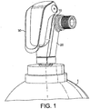
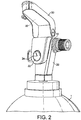
- a gas pressure vessel 1 comprising a valve assembly 10 is shown.
- the valve assembly comprises valve body 20 and lever 30 for actuating the valve mechanism (not shown).
- the valve assembly 10 further comprises a pressure gauge 22 having a visual display 24 (see Figure 2 ).
- the pressure gauge is in fluid communication with the interior of the pressure vessel 1 such that the visual display shows the pressure within the pressure vessel 1. This is standard in the art and is not described in detail here.
- the valve body 20 comprises a brass casting 23 which is substantially covered by a plastic casework 21.
- the visual display 24 of the pressure gauge 22 is substantially flush with the exterior surface of the casework 21.
- the pressure gauge 22 may be recessed within the casework 21 or brass casting 23, or may protrude from the casework 21 or brass casting 23.
- the casework 21 is not essential and may be omitted.
- the visual display 24 of the pressure gauge 22 is located behind the lever 30 when the lever is in the closed position (as illustrated in Figure 1 ).
- the rear surface 32 of the lever 30 abuts the visual display 24.
- the visual display 24 and/or the entire pressure gauge 22 may be recessed into the valve body 20.
- the valve body 20 in the region surrounding the pressure gauge 22 may abut the rear surface 32 of the lever 30 when the lever 20 is in the closed position.
- FIG. 3 shows an alternative valve assembly 110 mounted on a pressure vessel 1.
- the valve assembly 110 comprises a valve body 120 and lever 130.
- the lever 130 comprises an opening 134 which, in this example, contains a transparent member 136 which allows the visual display 24 to be viewed through the lever 130.
- the rear surface of the protective member 136 abuts the visual display 24.
- the visual display 24 and/or pressure gauge 22 may be recessed such that there is no contact between the rear surface of the protective member 136 and the visual display.
- the rear surface (not shown) of the lever 130 may abut the valve body in the vicinity surrounding the recessed gauge 22.
- the protective member 136 may be made of any suitable material such as Perspex RTM , other PMMAs or transparent grades of polycarbonates. Alternatively, the protective member 136 may comprise a wire mesh or any other suitable covering, or may be omitted. The protective member 136 may cover the whole of the external surface 131, or internal surface (not shown) of the lever 130.
- the lever 130 may comprise a transparent material such that the visual display 24 is visible through the lever when the lever is in the closed position.
- the lever 30, 130 abut any part of the valve body 20, 120 or gauge 22. It is envisaged that the gauge 22 may be located behind the lever 30, 130 without actually coming into contact with the lever 30, 130. In the context of this document, behind is to be understood to mean behind the rear surface of the lever 30, 130 and not, for example, on the opposite side of the valve body 20, 120 to the lever 30, 130.
Description
- The present invention relates to a lever operated valve. Specifically, the present invention relates to a lever operated valve in which the lever provides protection for a device mounted in or on the valve body, the device having a visual display.
- Cylinder valve assemblies for gas cylinders and the like are well known. Traditionally, cylinder valves are provided with a hand wheel which is operable by rotation to open and close the valve. More recently, cylinder valves which use levers to operate the valve mechanism have become known. Such a cylinder valve assembly is disclosed in
US 5,975,121 . - In lever operated valve designs, the length of the levers, and the arcs described by their opening/closing, are limited by the presence of valve guards and external components of the valve body.
- When in the closed position, levers often lie in close proximity to any sensitive devices such as pressure gauges, or other monitoring/display devices, the high pressure outlet, and any burst disc. The lever must therefore be positioned carefully in order to allow easy access to the lever for operation while providing adequate protection against accidental opening and damage due to impact.
- It is advantageous for valves to comprise instrumentation which tell users about the contents, pressure, temperature etc. of the cylinder. One such commonly used device is an analogue or digital pressure gauge. In lever operated valve designs, such gauges are commonly placed in the centre of the valve body, facing the user, with the lever positioned off to one side. This makes the valve "handed" and therefore harder to open for either left or right handed people.
- A valve design in which the pressure gauge and lever are both centrally mounted is disclosed in
US 2012/0175375 . In this design the lever receives the pressure gauge within an opening formed in the lever so that the pressure gauge may be seen when the lever is in the downward, or closed, position. - The present invention provides a valve assembly according to claim 1.
- The present invention is advantageous as it allows central mounting of both the lever and the gauge and also provides protection for the pressure gauge against impacts which might damage the visual display of the pressure gauge.
- At least a portion of the lever abuts at least a portion of the at least one device when the lever is in the closed position. This provides positive feedback of lever closure for the user and also provides an additional point of stability for the lever. Preferably, the lever abuts at least a portion of the visual display when in the closed position.
- The visual display is recessed within the valve body and at least a portion of the lever abuts at least a portion of the valve body when the lever is in the closed position. This provides positive feedback of closed position for the end user and also provides additional protection for the visual display.
- Preferably, at least a portion of the lever abuts at least a portion of the valve body in the vicinity of the valve body surrounding the visual display when the lever is in the closed position.
- In an alternative preferred embodiment, the at least one device protrudes from the valve body.
- In one embodiment, the lever substantially obscures the visual display from view when the lever is in the closed position. This provides positive visual confirmation to the user that the lever is in the closed position. In counterpoint to this, the visual display is visible only when the lever is in the open position again, giving confirmation to the user that the lever is in the open position (or not fully closed).
- In a further alternative embodiment, the lever comprises an opening through which the visual display may be viewed when the lever is in the closed position. This allows the user to ascertain the pressure within the gas cylinder without having to open the valve.
- Preferably, the opening contains, or is covered by, a protective member to protect the gauge and visual display from impact or accidental damage.
- The protective member preferably comprises a transparent member to allow the visual display to be easily viewed. In an alternative preferred embodiment, the lever comprises a transparent material.
- Examples of the invention will now be described with reference to the following drawings in which:
-
Figure 1 shows an isometric view of a lever valve assembly according to the present invention; -
Figure 2 shows the valve assembly ofFigure 1 in the open position; and -
Figure 3 shows an alternative embodiment of a valve assembly according to the present invention. - Referring to
Figure 1 , a gas pressure vessel 1 comprising avalve assembly 10 is shown. The valve assembly comprisesvalve body 20 and lever 30 for actuating the valve mechanism (not shown). Thevalve assembly 10 further comprises a pressure gauge 22 having a visual display 24 (seeFigure 2 ). Although not shown in the drawings, it will be understood by persons skilled in the art that the pressure gauge is in fluid communication with the interior of the pressure vessel 1 such that the visual display shows the pressure within the pressure vessel 1. This is standard in the art and is not described in detail here. - The
valve body 20 comprises a brass casting 23 which is substantially covered by a plastic casework 21. In this embodiment, thevisual display 24 of the pressure gauge 22 is substantially flush with the exterior surface of the casework 21. In an alternative design, the pressure gauge 22 may be recessed within the casework 21 or brass casting 23, or may protrude from the casework 21 or brass casting 23. The casework 21 is not essential and may be omitted. - As shown in
Figures 1 and2 , thevisual display 24 of the pressure gauge 22 is located behind thelever 30 when the lever is in the closed position (as illustrated inFigure 1 ). When in the closed position, therear surface 32 of thelever 30 abuts thevisual display 24. However, this is not essential and, as mentioned above, thevisual display 24 and/or the entire pressure gauge 22 may be recessed into thevalve body 20. In this case, thevalve body 20 in the region surrounding the pressure gauge 22 may abut therear surface 32 of thelever 30 when thelever 20 is in the closed position. -
Figure 3 shows analternative valve assembly 110 mounted on a pressure vessel 1. Thevalve assembly 110 comprises avalve body 120 andlever 130. Thelever 130 comprises anopening 134 which, in this example, contains atransparent member 136 which allows thevisual display 24 to be viewed through thelever 130. The rear surface of theprotective member 136 abuts thevisual display 24. However, in another embodiment, thevisual display 24 and/or pressure gauge 22 may be recessed such that there is no contact between the rear surface of theprotective member 136 and the visual display. In this case, the rear surface (not shown) of thelever 130 may abut the valve body in the vicinity surrounding the recessed gauge 22. - The
protective member 136 may be made of any suitable material such as PerspexRTM, other PMMAs or transparent grades of polycarbonates. Alternatively, theprotective member 136 may comprise a wire mesh or any other suitable covering, or may be omitted. Theprotective member 136 may cover the whole of theexternal surface 131, or internal surface (not shown) of thelever 130. - In an alternative embodiment (not shown) the
lever 130 may comprise a transparent material such that thevisual display 24 is visible through the lever when the lever is in the closed position. - It is not necessary in any of the above embodiments that the
lever valve body lever lever lever valve body lever - Although the invention has been described with reference to a mechanical pressure gauge 22 having an analogue display, it is to be understood that the present invention is also directed to any other type of device having a visual display that might be provided on or in the
valve body 20. Both analogue and digital devices are contemplated or any combination thereof. It is envisaged that there may be more than one such device located on or in thevalve body 20 and located behind thelever
Claims (10)
- A valve assembly (10) comprising a valve body (20) and a centrally mounted lever (30) for actuating the valve, the valve body (20) comprising at least one centrally mounted device (22) having a visual display (24), wherein the at least one device (22) is located such that, when the lever (30) is in a closed position, the visual display (24) is located behind the rear surface (32) of the lever (30) and characterised in that the visual display (24) is recessed within the valve body (20) and in that at least a portion of the lever (30) abuts at least a portion of the valve body (20) when the lever (30) is in the closed position.
- A valve assembly (10) as claimed in claim 1, wherein at least a portion of the lever (30) abuts at least a portion of the at least one device (22) when the lever (30) is in the closed position.
- A valve assembly (10) as claimed in claim 1 or 2, wherein at least a portion of the lever (30) abuts at least a portion of the visual display (24) when the lever (30) is in the closed position.
- A valve assembly (10) as claimed in claim 1, wherein at least a portion of the lever (30) abuts at least a portion of the valve body (20) in the vicinity of the valve body (20) surrounding the visual display (24) when the lever (30) is in the closed position.
- A valve assembly (10) as claimed in claim 1, wherein the at least one device (22) protrudes from the valve body (20).
- A valve assembly (10) as claimed in any preceding claim, wherein the lever (30) substantially obscures the visual display (24) from view when the lever (30) is in the closed position.
- A valve assembly (10) as claimed in any one of claims 1 to 5, wherein the lever (30) comprises an opening (134) through which the visual display (24) may be viewed when the lever (30) is in the closed position.
- A valve assembly (10) as claimed in claim 7, wherein the opening (134) contains, or is covered by, a protective member (136).
- A valve assembly (10) as claimed in claim 6, wherein the protective member (136) comprises a transparent member.
- A valve assembly (10) as claimed in any one of claims 1 to 5, wherein the lever (30) comprises a transparent material.
Applications Claiming Priority (2)
| Application Number | Priority Date | Filing Date | Title |
|---|---|---|---|
| GBGB1307473.7A GB201307473D0 (en) | 2013-04-25 | 2013-04-25 | Lever valve |
| PCT/GB2014/000157 WO2014174236A1 (en) | 2013-04-25 | 2014-04-25 | Lever valve |
Publications (2)
| Publication Number | Publication Date |
|---|---|
| EP2989371A1 EP2989371A1 (en) | 2016-03-02 |
| EP2989371B1 true EP2989371B1 (en) | 2021-12-01 |
Family
ID=48626814
Family Applications (1)
| Application Number | Title | Priority Date | Filing Date |
|---|---|---|---|
| EP14725915.4A Active EP2989371B1 (en) | 2013-04-25 | 2014-04-25 | Lever valve |
Country Status (9)
| Country | Link |
|---|---|
| US (1) | US20160047487A1 (en) |
| EP (1) | EP2989371B1 (en) |
| JP (1) | JP2016520177A (en) |
| KR (1) | KR20160003717A (en) |
| CN (1) | CN105378371A (en) |
| CA (1) | CA2910057A1 (en) |
| GB (1) | GB201307473D0 (en) |
| WO (1) | WO2014174236A1 (en) |
| ZA (1) | ZA201508211B (en) |
Families Citing this family (5)
| Publication number | Priority date | Publication date | Assignee | Title |
|---|---|---|---|---|
| WO2015131957A1 (en) * | 2014-03-07 | 2015-09-11 | Linde Aktiengesellschaft | A lever for a lever operated valve |
| GB2528920A (en) * | 2014-08-05 | 2016-02-10 | Linde Ag | A pressurised fluid container |
| ITUB20155082A1 (en) * | 2015-10-30 | 2017-04-30 | Mantegazza S R L | Valve for cylinder containing pressurized gas. |
| LU92937B1 (en) * | 2015-12-31 | 2017-07-21 | Luxembourg Patent Co | Tap assembly for gas cylinder with operating lever and cover |
| FR3048478B1 (en) * | 2016-03-03 | 2018-03-02 | L'air Liquide, Societe Anonyme Pour L'etude Et L'exploitation Des Procedes Georges Claude | PRESSURE FLUID VALVE |
Family Cites Families (11)
| Publication number | Priority date | Publication date | Assignee | Title |
|---|---|---|---|---|
| US1413504A (en) * | 1921-09-19 | 1922-04-18 | Bennett E Strickland | Valve |
| US2681707A (en) * | 1951-06-30 | 1954-06-22 | Specialties Dev Corp | Portable fire extinguisher |
| US3212333A (en) * | 1963-01-21 | 1965-10-19 | Kyota Tajiri | Liquid quantity measuring apparatus having magnetic indicating mechanism |
| US3270768A (en) * | 1963-03-07 | 1966-09-06 | Fyr Fyter Co | Valve and pressure gauge assembly |
| US4798203A (en) * | 1986-05-02 | 1989-01-17 | Respirator Research, Ltd. | Portable emergency breathing apparatus |
| CN2264288Y (en) * | 1996-07-22 | 1997-10-08 | 张建伍 | Consequent check active connecting lever valve |
| CN2359532Y (en) * | 1999-03-05 | 2000-01-19 | 陈辉民 | Pressure reducing valve with pressure meter |
| FR2865263B1 (en) * | 2004-01-20 | 2006-05-26 | Air Liquide | GAS DISTRIBUTION DEVICE WITH CONNECTION PROTECTION, ESPECIALLY FOR GAS BOTTLE |
| KR100836072B1 (en) * | 2007-05-29 | 2008-06-09 | 주식회사 메츠 | Digital safety device for a gas valve |
| CN201715233U (en) * | 2010-05-18 | 2011-01-19 | 浙江新劲空调设备有限公司 | Gas filling machine of automotive expansion valve |
| FR2970314B1 (en) * | 2011-01-11 | 2013-01-04 | Air Liquide | PRESSURIZED FLUID VALVE AND TANK PROVIDED WITH SUCH FAUCET |
-
2013
- 2013-04-25 GB GBGB1307473.7A patent/GB201307473D0/en not_active Ceased
-
2014
- 2014-04-25 CN CN201480029730.2A patent/CN105378371A/en active Pending
- 2014-04-25 WO PCT/GB2014/000157 patent/WO2014174236A1/en active Application Filing
- 2014-04-25 US US14/783,948 patent/US20160047487A1/en not_active Abandoned
- 2014-04-25 JP JP2016509535A patent/JP2016520177A/en active Pending
- 2014-04-25 EP EP14725915.4A patent/EP2989371B1/en active Active
- 2014-04-25 KR KR1020157032946A patent/KR20160003717A/en not_active Application Discontinuation
- 2014-04-25 CA CA2910057A patent/CA2910057A1/en not_active Abandoned
-
2015
- 2015-11-06 ZA ZA2015/08211A patent/ZA201508211B/en unknown
Non-Patent Citations (1)
| Title |
|---|
| None * |
Also Published As
| Publication number | Publication date |
|---|---|
| CA2910057A1 (en) | 2014-10-30 |
| WO2014174236A1 (en) | 2014-10-30 |
| JP2016520177A (en) | 2016-07-11 |
| US20160047487A1 (en) | 2016-02-18 |
| ZA201508211B (en) | 2017-01-25 |
| CN105378371A (en) | 2016-03-02 |
| KR20160003717A (en) | 2016-01-11 |
| GB201307473D0 (en) | 2013-06-12 |
| EP2989371A1 (en) | 2016-03-02 |
Similar Documents
| Publication | Publication Date | Title |
|---|---|---|
| EP2989371B1 (en) | Lever valve | |
| EP2717660B1 (en) | Back-face protection cover for tablet terminal | |
| WO2007125240A3 (en) | Protective cover for container and container provided with such a cover | |
| WO2007133817A3 (en) | Full opening and reclosable explosion vent apparatus | |
| MX2007006507A (en) | Visible open indicator . | |
| BRPI0911335A2 (en) | assembly comprising a tap and a protective cover, bottle comprising such an assembly. | |
| WO2008090806A1 (en) | Container for inspection | |
| US20160363234A1 (en) | A lever for a lever operated valve | |
| CN108063064B (en) | Limit switch shell with reset function | |
| CL2011000007A1 (en) | Pushbutton switch comprising an anti-blocking protection device that has a protective cover that is interposed between a button and a switch pushbutton, and which can be applied to a supporting structure of the switch to protect the pushbutton guiding means from the introduction of particles of powder and the like. | |
| EP0990825B1 (en) | Valve for a vessel for a pressurized fluid with a lever to control the passage of fluide | |
| TWI709024B (en) | Display protecting device | |
| CN105493209B (en) | Bursting device for autoclave appts | |
| US20160084443A1 (en) | A pressurised fluid container | |
| KR100845876B1 (en) | Valve controller box | |
| JP3651331B2 (en) | Metal bottle | |
| US20130048894A1 (en) | Continuous turn bi-directional air vent actuator | |
| CN108400031B (en) | Reset key of limit switch | |
| WO2014187733A2 (en) | Valve guard | |
| WO2014187817A2 (en) | Tamper evidence | |
| ZA200903062B (en) | Device for a container for nonferrous molten metal, having a locking unit and a protective cap | |
| ITMI980637U1 (en) | STRUCTURE OF THE VALVE OPERATING GROUP OF FIRE EXTINGUISHERS AND SIMILAR WITH SAFETY MEANS | |
| ITPD20110084U1 (en) | ADVANCED SEALING SEAL | |
| ITMI990113U1 (en) | PROTECTIVE OIL MILK CONTAINER FOR ENGINES | |
| TWM500537U (en) | Double-layered container |
Legal Events
| Date | Code | Title | Description |
|---|---|---|---|
| PUAI | Public reference made under article 153(3) epc to a published international application that has entered the european phase |
Free format text: ORIGINAL CODE: 0009012 |
|
| 17P | Request for examination filed |
Effective date: 20151124 |
|
| AK | Designated contracting states |
Kind code of ref document: A1 Designated state(s): AL AT BE BG CH CY CZ DE DK EE ES FI FR GB GR HR HU IE IS IT LI LT LU LV MC MK MT NL NO PL PT RO RS SE SI SK SM TR |
|
| AX | Request for extension of the european patent |
Extension state: BA ME |
|
| DAX | Request for extension of the european patent (deleted) | ||
| STAA | Information on the status of an ep patent application or granted ep patent |
Free format text: STATUS: EXAMINATION IS IN PROGRESS |
|
| 17Q | First examination report despatched |
Effective date: 20181122 |
|
| STAA | Information on the status of an ep patent application or granted ep patent |
Free format text: STATUS: EXAMINATION IS IN PROGRESS |
|
| RAP1 | Party data changed (applicant data changed or rights of an application transferred) |
Owner name: LINDE GMBH |
|
| GRAP | Despatch of communication of intention to grant a patent |
Free format text: ORIGINAL CODE: EPIDOSNIGR1 |
|
| STAA | Information on the status of an ep patent application or granted ep patent |
Free format text: STATUS: GRANT OF PATENT IS INTENDED |
|
| INTG | Intention to grant announced |
Effective date: 20210622 |
|
| GRAS | Grant fee paid |
Free format text: ORIGINAL CODE: EPIDOSNIGR3 |
|
| GRAA | (expected) grant |
Free format text: ORIGINAL CODE: 0009210 |
|
| STAA | Information on the status of an ep patent application or granted ep patent |
Free format text: STATUS: THE PATENT HAS BEEN GRANTED |
|
| AK | Designated contracting states |
Kind code of ref document: B1 Designated state(s): AL AT BE BG CH CY CZ DE DK EE ES FI FR GB GR HR HU IE IS IT LI LT LU LV MC MK MT NL NO PL PT RO RS SE SI SK SM TR |
|
| REG | Reference to a national code |
Ref country code: GB Ref legal event code: FG4D |
|
| REG | Reference to a national code |
Ref country code: AT Ref legal event code: REF Ref document number: 1452088 Country of ref document: AT Kind code of ref document: T Effective date: 20211215 Ref country code: CH Ref legal event code: EP |
|
| REG | Reference to a national code |
Ref country code: IE Ref legal event code: FG4D |
|
| REG | Reference to a national code |
Ref country code: DE Ref legal event code: R096 Ref document number: 602014081503 Country of ref document: DE |
|
| REG | Reference to a national code |
Ref country code: SE Ref legal event code: TRGR |
|
| REG | Reference to a national code |
Ref country code: NO Ref legal event code: T2 Effective date: 20211201 |
|
| REG | Reference to a national code |
Ref country code: LT Ref legal event code: MG9D |
|
| REG | Reference to a national code |
Ref country code: NL Ref legal event code: MP Effective date: 20211201 |
|
| PG25 | Lapsed in a contracting state [announced via postgrant information from national office to epo] |
Ref country code: RS Free format text: LAPSE BECAUSE OF FAILURE TO SUBMIT A TRANSLATION OF THE DESCRIPTION OR TO PAY THE FEE WITHIN THE PRESCRIBED TIME-LIMIT Effective date: 20211201 Ref country code: LT Free format text: LAPSE BECAUSE OF FAILURE TO SUBMIT A TRANSLATION OF THE DESCRIPTION OR TO PAY THE FEE WITHIN THE PRESCRIBED TIME-LIMIT Effective date: 20211201 Ref country code: FI Free format text: LAPSE BECAUSE OF FAILURE TO SUBMIT A TRANSLATION OF THE DESCRIPTION OR TO PAY THE FEE WITHIN THE PRESCRIBED TIME-LIMIT Effective date: 20211201 Ref country code: BG Free format text: LAPSE BECAUSE OF FAILURE TO SUBMIT A TRANSLATION OF THE DESCRIPTION OR TO PAY THE FEE WITHIN THE PRESCRIBED TIME-LIMIT Effective date: 20220301 |
|
| PG25 | Lapsed in a contracting state [announced via postgrant information from national office to epo] |
Ref country code: PL Free format text: LAPSE BECAUSE OF FAILURE TO SUBMIT A TRANSLATION OF THE DESCRIPTION OR TO PAY THE FEE WITHIN THE PRESCRIBED TIME-LIMIT Effective date: 20211201 Ref country code: LV Free format text: LAPSE BECAUSE OF FAILURE TO SUBMIT A TRANSLATION OF THE DESCRIPTION OR TO PAY THE FEE WITHIN THE PRESCRIBED TIME-LIMIT Effective date: 20211201 Ref country code: HR Free format text: LAPSE BECAUSE OF FAILURE TO SUBMIT A TRANSLATION OF THE DESCRIPTION OR TO PAY THE FEE WITHIN THE PRESCRIBED TIME-LIMIT Effective date: 20211201 Ref country code: GR Free format text: LAPSE BECAUSE OF FAILURE TO SUBMIT A TRANSLATION OF THE DESCRIPTION OR TO PAY THE FEE WITHIN THE PRESCRIBED TIME-LIMIT Effective date: 20220302 Ref country code: ES Free format text: LAPSE BECAUSE OF FAILURE TO SUBMIT A TRANSLATION OF THE DESCRIPTION OR TO PAY THE FEE WITHIN THE PRESCRIBED TIME-LIMIT Effective date: 20211201 |
|
| PG25 | Lapsed in a contracting state [announced via postgrant information from national office to epo] |
Ref country code: NL Free format text: LAPSE BECAUSE OF FAILURE TO SUBMIT A TRANSLATION OF THE DESCRIPTION OR TO PAY THE FEE WITHIN THE PRESCRIBED TIME-LIMIT Effective date: 20211201 |
|
| PG25 | Lapsed in a contracting state [announced via postgrant information from national office to epo] |
Ref country code: SM Free format text: LAPSE BECAUSE OF FAILURE TO SUBMIT A TRANSLATION OF THE DESCRIPTION OR TO PAY THE FEE WITHIN THE PRESCRIBED TIME-LIMIT Effective date: 20211201 Ref country code: SK Free format text: LAPSE BECAUSE OF FAILURE TO SUBMIT A TRANSLATION OF THE DESCRIPTION OR TO PAY THE FEE WITHIN THE PRESCRIBED TIME-LIMIT Effective date: 20211201 Ref country code: RO Free format text: LAPSE BECAUSE OF FAILURE TO SUBMIT A TRANSLATION OF THE DESCRIPTION OR TO PAY THE FEE WITHIN THE PRESCRIBED TIME-LIMIT Effective date: 20211201 Ref country code: PT Free format text: LAPSE BECAUSE OF FAILURE TO SUBMIT A TRANSLATION OF THE DESCRIPTION OR TO PAY THE FEE WITHIN THE PRESCRIBED TIME-LIMIT Effective date: 20220401 Ref country code: EE Free format text: LAPSE BECAUSE OF FAILURE TO SUBMIT A TRANSLATION OF THE DESCRIPTION OR TO PAY THE FEE WITHIN THE PRESCRIBED TIME-LIMIT Effective date: 20211201 Ref country code: CZ Free format text: LAPSE BECAUSE OF FAILURE TO SUBMIT A TRANSLATION OF THE DESCRIPTION OR TO PAY THE FEE WITHIN THE PRESCRIBED TIME-LIMIT Effective date: 20211201 |
|
| PGFP | Annual fee paid to national office [announced via postgrant information from national office to epo] |
Ref country code: IT Payment date: 20220429 Year of fee payment: 9 |
|
| REG | Reference to a national code |
Ref country code: DE Ref legal event code: R097 Ref document number: 602014081503 Country of ref document: DE |
|
| PG25 | Lapsed in a contracting state [announced via postgrant information from national office to epo] |
Ref country code: IS Free format text: LAPSE BECAUSE OF FAILURE TO SUBMIT A TRANSLATION OF THE DESCRIPTION OR TO PAY THE FEE WITHIN THE PRESCRIBED TIME-LIMIT Effective date: 20220401 |
|
| PLBE | No opposition filed within time limit |
Free format text: ORIGINAL CODE: 0009261 |
|
| STAA | Information on the status of an ep patent application or granted ep patent |
Free format text: STATUS: NO OPPOSITION FILED WITHIN TIME LIMIT |
|
| PG25 | Lapsed in a contracting state [announced via postgrant information from national office to epo] |
Ref country code: DK Free format text: LAPSE BECAUSE OF FAILURE TO SUBMIT A TRANSLATION OF THE DESCRIPTION OR TO PAY THE FEE WITHIN THE PRESCRIBED TIME-LIMIT Effective date: 20211201 Ref country code: AL Free format text: LAPSE BECAUSE OF FAILURE TO SUBMIT A TRANSLATION OF THE DESCRIPTION OR TO PAY THE FEE WITHIN THE PRESCRIBED TIME-LIMIT Effective date: 20211201 |
|
| 26N | No opposition filed |
Effective date: 20220902 |
|
| PG25 | Lapsed in a contracting state [announced via postgrant information from national office to epo] |
Ref country code: SI Free format text: LAPSE BECAUSE OF FAILURE TO SUBMIT A TRANSLATION OF THE DESCRIPTION OR TO PAY THE FEE WITHIN THE PRESCRIBED TIME-LIMIT Effective date: 20211201 |
|
| REG | Reference to a national code |
Ref country code: BE Ref legal event code: MM Effective date: 20220430 |
|
| PG25 | Lapsed in a contracting state [announced via postgrant information from national office to epo] |
Ref country code: MC Free format text: LAPSE BECAUSE OF FAILURE TO SUBMIT A TRANSLATION OF THE DESCRIPTION OR TO PAY THE FEE WITHIN THE PRESCRIBED TIME-LIMIT Effective date: 20211201 Ref country code: LU Free format text: LAPSE BECAUSE OF NON-PAYMENT OF DUE FEES Effective date: 20220425 |
|
| PG25 | Lapsed in a contracting state [announced via postgrant information from national office to epo] |
Ref country code: BE Free format text: LAPSE BECAUSE OF NON-PAYMENT OF DUE FEES Effective date: 20220430 |
|
| PG25 | Lapsed in a contracting state [announced via postgrant information from national office to epo] |
Ref country code: IE Free format text: LAPSE BECAUSE OF NON-PAYMENT OF DUE FEES Effective date: 20220425 |
|
| PG25 | Lapsed in a contracting state [announced via postgrant information from national office to epo] |
Ref country code: IT Free format text: LAPSE BECAUSE OF NON-PAYMENT OF DUE FEES Effective date: 20220425 |
|
| PGFP | Annual fee paid to national office [announced via postgrant information from national office to epo] |
Ref country code: NO Payment date: 20230418 Year of fee payment: 10 Ref country code: FR Payment date: 20230417 Year of fee payment: 10 Ref country code: DE Payment date: 20230418 Year of fee payment: 10 Ref country code: CH Payment date: 20230502 Year of fee payment: 10 |
|
| PGFP | Annual fee paid to national office [announced via postgrant information from national office to epo] |
Ref country code: SE Payment date: 20230419 Year of fee payment: 10 Ref country code: AT Payment date: 20230414 Year of fee payment: 10 |
|
| PGFP | Annual fee paid to national office [announced via postgrant information from national office to epo] |
Ref country code: GB Payment date: 20230420 Year of fee payment: 10 |
|
| PG25 | Lapsed in a contracting state [announced via postgrant information from national office to epo] |
Ref country code: HU Free format text: LAPSE BECAUSE OF FAILURE TO SUBMIT A TRANSLATION OF THE DESCRIPTION OR TO PAY THE FEE WITHIN THE PRESCRIBED TIME-LIMIT; INVALID AB INITIO Effective date: 20140425 |