EP2988872B1 - Dispositifs microfluidiques pour dosages automatisés - Google Patents
Dispositifs microfluidiques pour dosages automatisés Download PDFInfo
- Publication number
- EP2988872B1 EP2988872B1 EP15780234.9A EP15780234A EP2988872B1 EP 2988872 B1 EP2988872 B1 EP 2988872B1 EP 15780234 A EP15780234 A EP 15780234A EP 2988872 B1 EP2988872 B1 EP 2988872B1
- Authority
- EP
- European Patent Office
- Prior art keywords
- well
- assay
- cover
- cartridge
- containers
- Prior art date
- Legal status (The legal status is an assumption and is not a legal conclusion. Google has not performed a legal analysis and makes no representation as to the accuracy of the status listed.)
- Not-in-force
Links
- 238000003556 assay Methods 0.000 title claims description 193
- 239000007788 liquid Substances 0.000 claims description 93
- 239000003153 chemical reaction reagent Substances 0.000 claims description 74
- 125000006850 spacer group Chemical group 0.000 claims description 49
- 238000000034 method Methods 0.000 claims description 33
- 239000000872 buffer Substances 0.000 claims description 26
- 150000007523 nucleic acids Chemical class 0.000 claims description 23
- 102000039446 nucleic acids Human genes 0.000 claims description 22
- 108020004707 nucleic acids Proteins 0.000 claims description 22
- 239000012530 fluid Substances 0.000 claims description 20
- 108090000623 proteins and genes Proteins 0.000 claims description 17
- 102000004169 proteins and genes Human genes 0.000 claims description 16
- 229920000642 polymer Polymers 0.000 claims description 12
- 238000003018 immunoassay Methods 0.000 claims description 10
- 239000011521 glass Substances 0.000 claims description 8
- 238000005406 washing Methods 0.000 claims description 7
- 239000002184 metal Substances 0.000 claims description 6
- 229910052751 metal Inorganic materials 0.000 claims description 6
- 238000007899 nucleic acid hybridization Methods 0.000 claims description 6
- 239000000919 ceramic Substances 0.000 claims description 5
- 239000010703 silicon Substances 0.000 claims description 3
- 229910052710 silicon Inorganic materials 0.000 claims description 3
- 238000003825 pressing Methods 0.000 claims 1
- 150000001413 amino acids Chemical class 0.000 description 38
- 239000000523 sample Substances 0.000 description 38
- 235000001014 amino acid Nutrition 0.000 description 37
- 229940024606 amino acid Drugs 0.000 description 37
- 239000003795 chemical substances by application Substances 0.000 description 15
- 239000000463 material Substances 0.000 description 15
- 235000018102 proteins Nutrition 0.000 description 15
- 210000004027 cell Anatomy 0.000 description 13
- 239000002773 nucleotide Substances 0.000 description 12
- 125000003729 nucleotide group Chemical group 0.000 description 12
- 239000000427 antigen Substances 0.000 description 11
- 238000001514 detection method Methods 0.000 description 11
- 108090000765 processed proteins & peptides Proteins 0.000 description 11
- 239000007787 solid Substances 0.000 description 11
- 108020004414 DNA Proteins 0.000 description 10
- 108091007433 antigens Proteins 0.000 description 10
- 102000036639 antigens Human genes 0.000 description 10
- 239000000306 component Substances 0.000 description 10
- 239000004033 plastic Substances 0.000 description 9
- 229920003023 plastic Polymers 0.000 description 9
- 108091032973 (ribonucleotides)n+m Proteins 0.000 description 8
- 229920000089 Cyclic olefin copolymer Polymers 0.000 description 8
- 239000012491 analyte Substances 0.000 description 8
- 238000007789 sealing Methods 0.000 description 8
- 239000000126 substance Substances 0.000 description 8
- 150000001875 compounds Chemical class 0.000 description 7
- -1 e.g. Polymers 0.000 description 7
- 239000012634 fragment Substances 0.000 description 7
- 239000007789 gas Substances 0.000 description 7
- 229920001184 polypeptide Polymers 0.000 description 7
- 102000004196 processed proteins & peptides Human genes 0.000 description 7
- 238000012360 testing method Methods 0.000 description 7
- ZHNUHDYFZUAESO-UHFFFAOYSA-N Formamide Chemical compound NC=O ZHNUHDYFZUAESO-UHFFFAOYSA-N 0.000 description 6
- 230000000295 complement effect Effects 0.000 description 6
- 229920001971 elastomer Polymers 0.000 description 6
- 239000000203 mixture Substances 0.000 description 6
- 108091033319 polynucleotide Proteins 0.000 description 6
- 102000040430 polynucleotide Human genes 0.000 description 6
- 239000002157 polynucleotide Substances 0.000 description 6
- 230000008685 targeting Effects 0.000 description 6
- 108090000790 Enzymes Proteins 0.000 description 5
- 102000004190 Enzymes Human genes 0.000 description 5
- 230000003321 amplification Effects 0.000 description 5
- 239000012472 biological sample Substances 0.000 description 5
- 229940088598 enzyme Drugs 0.000 description 5
- 238000009396 hybridization Methods 0.000 description 5
- 238000003199 nucleic acid amplification method Methods 0.000 description 5
- 238000012545 processing Methods 0.000 description 5
- 238000006467 substitution reaction Methods 0.000 description 5
- 108091023037 Aptamer Chemical class 0.000 description 4
- 239000004713 Cyclic olefin copolymer Substances 0.000 description 4
- 102000053602 DNA Human genes 0.000 description 4
- 108010021625 Immunoglobulin Fragments Proteins 0.000 description 4
- 238000007836 assay cartridge Methods 0.000 description 4
- 238000004166 bioassay Methods 0.000 description 4
- 239000004205 dimethyl polysiloxane Substances 0.000 description 4
- 238000010494 dissociation reaction Methods 0.000 description 4
- 230000005593 dissociations Effects 0.000 description 4
- 125000005647 linker group Chemical group 0.000 description 4
- 239000011159 matrix material Substances 0.000 description 4
- 229920000435 poly(dimethylsiloxane) Polymers 0.000 description 4
- 229920003229 poly(methyl methacrylate) Polymers 0.000 description 4
- 238000003752 polymerase chain reaction Methods 0.000 description 4
- 239000004926 polymethyl methacrylate Substances 0.000 description 4
- 239000005060 rubber Substances 0.000 description 4
- 239000000758 substrate Substances 0.000 description 4
- 108060003951 Immunoglobulin Proteins 0.000 description 3
- 102000008394 Immunoglobulin Fragments Human genes 0.000 description 3
- FFEARJCKVFRZRR-BYPYZUCNSA-N L-methionine Chemical group CSCC[C@H](N)C(O)=O FFEARJCKVFRZRR-BYPYZUCNSA-N 0.000 description 3
- 238000007792 addition Methods 0.000 description 3
- 230000004888 barrier function Effects 0.000 description 3
- 239000011230 binding agent Substances 0.000 description 3
- 230000015572 biosynthetic process Effects 0.000 description 3
- 150000001720 carbohydrates Chemical class 0.000 description 3
- 239000000539 dimer Substances 0.000 description 3
- 230000002068 genetic effect Effects 0.000 description 3
- 102000018358 immunoglobulin Human genes 0.000 description 3
- 238000001114 immunoprecipitation Methods 0.000 description 3
- 150000002632 lipids Chemical class 0.000 description 3
- 230000007246 mechanism Effects 0.000 description 3
- 229930182817 methionine Chemical group 0.000 description 3
- 239000000178 monomer Substances 0.000 description 3
- 239000011534 wash buffer Substances 0.000 description 3
- YBJHBAHKTGYVGT-ZKWXMUAHSA-N (+)-Biotin Chemical compound N1C(=O)N[C@@H]2[C@H](CCCCC(=O)O)SC[C@@H]21 YBJHBAHKTGYVGT-ZKWXMUAHSA-N 0.000 description 2
- BWGNESOTFCXPMA-UHFFFAOYSA-N Dihydrogen disulfide Chemical compound SS BWGNESOTFCXPMA-UHFFFAOYSA-N 0.000 description 2
- 238000002965 ELISA Methods 0.000 description 2
- DHMQDGOQFOQNFH-UHFFFAOYSA-N Glycine Chemical compound NCC(O)=O DHMQDGOQFOQNFH-UHFFFAOYSA-N 0.000 description 2
- 102000003886 Glycoproteins Human genes 0.000 description 2
- 108090000288 Glycoproteins Proteins 0.000 description 2
- 108700005091 Immunoglobulin Genes Proteins 0.000 description 2
- LRQKBLKVPFOOQJ-YFKPBYRVSA-N L-norleucine Chemical group CCCC[C@H]([NH3+])C([O-])=O LRQKBLKVPFOOQJ-YFKPBYRVSA-N 0.000 description 2
- 108010089430 Phosphoproteins Proteins 0.000 description 2
- 102000007982 Phosphoproteins Human genes 0.000 description 2
- 108020004511 Recombinant DNA Proteins 0.000 description 2
- 108091028664 Ribonucleotide Proteins 0.000 description 2
- 108020004682 Single-Stranded DNA Proteins 0.000 description 2
- FAPWRFPIFSIZLT-UHFFFAOYSA-M Sodium chloride Chemical compound [Na+].[Cl-] FAPWRFPIFSIZLT-UHFFFAOYSA-M 0.000 description 2
- 239000000853 adhesive Substances 0.000 description 2
- 230000001070 adhesive effect Effects 0.000 description 2
- 125000003277 amino group Chemical group 0.000 description 2
- 230000000903 blocking effect Effects 0.000 description 2
- 239000007853 buffer solution Substances 0.000 description 2
- 239000002458 cell surface marker Substances 0.000 description 2
- 230000001413 cellular effect Effects 0.000 description 2
- 239000011248 coating agent Substances 0.000 description 2
- 238000000576 coating method Methods 0.000 description 2
- 239000002299 complementary DNA Substances 0.000 description 2
- 239000002131 composite material Substances 0.000 description 2
- 239000000356 contaminant Substances 0.000 description 2
- 238000001816 cooling Methods 0.000 description 2
- 238000012217 deletion Methods 0.000 description 2
- 230000037430 deletion Effects 0.000 description 2
- 239000005547 deoxyribonucleotide Substances 0.000 description 2
- 125000002637 deoxyribonucleotide group Chemical group 0.000 description 2
- 230000029087 digestion Effects 0.000 description 2
- 239000000806 elastomer Substances 0.000 description 2
- 238000005516 engineering process Methods 0.000 description 2
- 239000000834 fixative Substances 0.000 description 2
- 230000006870 function Effects 0.000 description 2
- 125000000524 functional group Chemical group 0.000 description 2
- 230000036571 hydration Effects 0.000 description 2
- 238000006703 hydration reaction Methods 0.000 description 2
- 230000002163 immunogen Effects 0.000 description 2
- 229940072221 immunoglobulins Drugs 0.000 description 2
- 239000003547 immunosorbent Substances 0.000 description 2
- 238000011534 incubation Methods 0.000 description 2
- 238000002372 labelling Methods 0.000 description 2
- 238000005259 measurement Methods 0.000 description 2
- 238000012986 modification Methods 0.000 description 2
- 230000004048 modification Effects 0.000 description 2
- 230000037361 pathway Effects 0.000 description 2
- 239000004417 polycarbonate Substances 0.000 description 2
- 229920000515 polycarbonate Polymers 0.000 description 2
- 238000003127 radioimmunoassay Methods 0.000 description 2
- 238000011160 research Methods 0.000 description 2
- 238000012552 review Methods 0.000 description 2
- 239000002336 ribonucleotide Substances 0.000 description 2
- 125000002652 ribonucleotide group Chemical group 0.000 description 2
- 238000000926 separation method Methods 0.000 description 2
- 239000007790 solid phase Substances 0.000 description 2
- 239000002904 solvent Substances 0.000 description 2
- 239000011550 stock solution Substances 0.000 description 2
- 229920001169 thermoplastic Polymers 0.000 description 2
- 239000004416 thermosoftening plastic Substances 0.000 description 2
- 238000011144 upstream manufacturing Methods 0.000 description 2
- 239000006226 wash reagent Substances 0.000 description 2
- 102000040650 (ribonucleotides)n+m Human genes 0.000 description 1
- UKAUYVFTDYCKQA-UHFFFAOYSA-N -2-Amino-4-hydroxybutanoic acid Natural products OC(=O)C(N)CCO UKAUYVFTDYCKQA-UHFFFAOYSA-N 0.000 description 1
- 108700028369 Alleles Proteins 0.000 description 1
- 239000004475 Arginine Substances 0.000 description 1
- DCXYFEDJOCDNAF-UHFFFAOYSA-N Asparagine Natural products OC(=O)C(N)CC(N)=O DCXYFEDJOCDNAF-UHFFFAOYSA-N 0.000 description 1
- OKTJSMMVPCPJKN-UHFFFAOYSA-N Carbon Chemical compound [C] OKTJSMMVPCPJKN-UHFFFAOYSA-N 0.000 description 1
- 241000557626 Corvus corax Species 0.000 description 1
- SHIBSTMRCDJXLN-UHFFFAOYSA-N Digoxigenin Natural products C1CC(C2C(C3(C)CCC(O)CC3CC2)CC2O)(O)C2(C)C1C1=CC(=O)OC1 SHIBSTMRCDJXLN-UHFFFAOYSA-N 0.000 description 1
- 229920001875 Ebonite Polymers 0.000 description 1
- WHUUTDBJXJRKMK-UHFFFAOYSA-N Glutamic acid Natural products OC(=O)C(N)CCC(O)=O WHUUTDBJXJRKMK-UHFFFAOYSA-N 0.000 description 1
- 239000004471 Glycine Substances 0.000 description 1
- PMMYEEVYMWASQN-DMTCNVIQSA-N Hydroxyproline Chemical compound O[C@H]1CN[C@H](C(O)=O)C1 PMMYEEVYMWASQN-DMTCNVIQSA-N 0.000 description 1
- 102000006496 Immunoglobulin Heavy Chains Human genes 0.000 description 1
- 108010019476 Immunoglobulin Heavy Chains Proteins 0.000 description 1
- 102000013463 Immunoglobulin Light Chains Human genes 0.000 description 1
- 108010065825 Immunoglobulin Light Chains Proteins 0.000 description 1
- QNAYBMKLOCPYGJ-REOHCLBHSA-N L-alanine Chemical compound C[C@H](N)C(O)=O QNAYBMKLOCPYGJ-REOHCLBHSA-N 0.000 description 1
- DCXYFEDJOCDNAF-REOHCLBHSA-N L-asparagine Chemical compound OC(=O)[C@@H](N)CC(N)=O DCXYFEDJOCDNAF-REOHCLBHSA-N 0.000 description 1
- CKLJMWTZIZZHCS-REOHCLBHSA-N L-aspartic acid Chemical compound OC(=O)[C@@H](N)CC(O)=O CKLJMWTZIZZHCS-REOHCLBHSA-N 0.000 description 1
- UKAUYVFTDYCKQA-VKHMYHEASA-N L-homoserine Chemical group OC(=O)[C@@H](N)CCO UKAUYVFTDYCKQA-VKHMYHEASA-N 0.000 description 1
- AGPKZVBTJJNPAG-WHFBIAKZSA-N L-isoleucine Chemical compound CC[C@H](C)[C@H](N)C(O)=O AGPKZVBTJJNPAG-WHFBIAKZSA-N 0.000 description 1
- ROHFNLRQFUQHCH-YFKPBYRVSA-N L-leucine Chemical compound CC(C)C[C@H](N)C(O)=O ROHFNLRQFUQHCH-YFKPBYRVSA-N 0.000 description 1
- QEFRNWWLZKMPFJ-ZXPFJRLXSA-N L-methionine (R)-S-oxide Chemical group C[S@@](=O)CC[C@H]([NH3+])C([O-])=O QEFRNWWLZKMPFJ-ZXPFJRLXSA-N 0.000 description 1
- QEFRNWWLZKMPFJ-UHFFFAOYSA-N L-methionine sulphoxide Chemical group CS(=O)CCC(N)C(O)=O QEFRNWWLZKMPFJ-UHFFFAOYSA-N 0.000 description 1
- COLNVLDHVKWLRT-QMMMGPOBSA-N L-phenylalanine Chemical compound OC(=O)[C@@H](N)CC1=CC=CC=C1 COLNVLDHVKWLRT-QMMMGPOBSA-N 0.000 description 1
- QIVBCDIJIAJPQS-VIFPVBQESA-N L-tryptophane Chemical compound C1=CC=C2C(C[C@H](N)C(O)=O)=CNC2=C1 QIVBCDIJIAJPQS-VIFPVBQESA-N 0.000 description 1
- OUYCCCASQSFEME-QMMMGPOBSA-N L-tyrosine Chemical compound OC(=O)[C@@H](N)CC1=CC=C(O)C=C1 OUYCCCASQSFEME-QMMMGPOBSA-N 0.000 description 1
- KZSNJWFQEVHDMF-BYPYZUCNSA-N L-valine Chemical compound CC(C)[C@H](N)C(O)=O KZSNJWFQEVHDMF-BYPYZUCNSA-N 0.000 description 1
- ROHFNLRQFUQHCH-UHFFFAOYSA-N Leucine Natural products CC(C)CC(N)C(O)=O ROHFNLRQFUQHCH-UHFFFAOYSA-N 0.000 description 1
- 239000004472 Lysine Substances 0.000 description 1
- KDXKERNSBIXSRK-UHFFFAOYSA-N Lysine Natural products NCCCCC(N)C(O)=O KDXKERNSBIXSRK-UHFFFAOYSA-N 0.000 description 1
- OKIZCWYLBDKLSU-UHFFFAOYSA-M N,N,N-Trimethylmethanaminium chloride Chemical compound [Cl-].C[N+](C)(C)C OKIZCWYLBDKLSU-UHFFFAOYSA-M 0.000 description 1
- 238000005481 NMR spectroscopy Methods 0.000 description 1
- 239000000020 Nitrocellulose Substances 0.000 description 1
- 238000000636 Northern blotting Methods 0.000 description 1
- 102000057297 Pepsin A Human genes 0.000 description 1
- 108090000284 Pepsin A Proteins 0.000 description 1
- 102000035195 Peptidases Human genes 0.000 description 1
- 108091005804 Peptidases Proteins 0.000 description 1
- 239000004952 Polyamide Substances 0.000 description 1
- 229920000805 Polyaspartic acid Polymers 0.000 description 1
- 108010020346 Polyglutamic Acid Proteins 0.000 description 1
- 108010039918 Polylysine Proteins 0.000 description 1
- MTCFGRXMJLQNBG-UHFFFAOYSA-N Serine Natural products OCC(N)C(O)=O MTCFGRXMJLQNBG-UHFFFAOYSA-N 0.000 description 1
- 108020004459 Small interfering RNA Proteins 0.000 description 1
- 238000002105 Southern blotting Methods 0.000 description 1
- AYFVYJQAPQTCCC-UHFFFAOYSA-N Threonine Natural products CC(O)C(N)C(O)=O AYFVYJQAPQTCCC-UHFFFAOYSA-N 0.000 description 1
- 239000004473 Threonine Substances 0.000 description 1
- 101710120037 Toxin CcdB Proteins 0.000 description 1
- QIVBCDIJIAJPQS-UHFFFAOYSA-N Tryptophan Natural products C1=CC=C2C(CC(N)C(O)=O)=CNC2=C1 QIVBCDIJIAJPQS-UHFFFAOYSA-N 0.000 description 1
- KZSNJWFQEVHDMF-UHFFFAOYSA-N Valine Natural products CC(C)C(N)C(O)=O KZSNJWFQEVHDMF-UHFFFAOYSA-N 0.000 description 1
- 241000700605 Viruses Species 0.000 description 1
- 239000002253 acid Substances 0.000 description 1
- 150000007513 acids Chemical class 0.000 description 1
- 230000009471 action Effects 0.000 description 1
- 230000001464 adherent effect Effects 0.000 description 1
- 235000004279 alanine Nutrition 0.000 description 1
- 230000004075 alteration Effects 0.000 description 1
- 125000000539 amino acid group Chemical group 0.000 description 1
- QGZKDVFQNNGYKY-UHFFFAOYSA-O ammonium group Chemical group [NH4+] QGZKDVFQNNGYKY-UHFFFAOYSA-O 0.000 description 1
- 239000012062 aqueous buffer Substances 0.000 description 1
- 239000007864 aqueous solution Substances 0.000 description 1
- 239000002152 aqueous-organic solution Substances 0.000 description 1
- ODKSFYDXXFIFQN-UHFFFAOYSA-N arginine Natural products OC(=O)C(N)CCCNC(N)=N ODKSFYDXXFIFQN-UHFFFAOYSA-N 0.000 description 1
- 238000003491 array Methods 0.000 description 1
- 235000009582 asparagine Nutrition 0.000 description 1
- 229960001230 asparagine Drugs 0.000 description 1
- 235000003704 aspartic acid Nutrition 0.000 description 1
- 239000002585 base Substances 0.000 description 1
- OQFSQFPPLPISGP-UHFFFAOYSA-N beta-carboxyaspartic acid Natural products OC(=O)C(N)C(C(O)=O)C(O)=O OQFSQFPPLPISGP-UHFFFAOYSA-N 0.000 description 1
- 238000001574 biopsy Methods 0.000 description 1
- 229960002685 biotin Drugs 0.000 description 1
- 235000020958 biotin Nutrition 0.000 description 1
- 239000011616 biotin Substances 0.000 description 1
- 210000004369 blood Anatomy 0.000 description 1
- 239000008280 blood Substances 0.000 description 1
- 239000012503 blood component Substances 0.000 description 1
- 210000001124 body fluid Anatomy 0.000 description 1
- 229910052799 carbon Inorganic materials 0.000 description 1
- 125000003178 carboxy group Chemical group [H]OC(*)=O 0.000 description 1
- UHBYWPGGCSDKFX-UHFFFAOYSA-N carboxyglutamic acid Chemical compound OC(=O)C(N)CC(C(O)=O)C(O)=O UHBYWPGGCSDKFX-UHFFFAOYSA-N 0.000 description 1
- 125000002843 carboxylic acid group Chemical group 0.000 description 1
- 229920002678 cellulose Polymers 0.000 description 1
- 235000010980 cellulose Nutrition 0.000 description 1
- 238000002144 chemical decomposition reaction Methods 0.000 description 1
- 238000006243 chemical reaction Methods 0.000 description 1
- 230000000052 comparative effect Effects 0.000 description 1
- 238000012875 competitive assay Methods 0.000 description 1
- 230000002860 competitive effect Effects 0.000 description 1
- 230000001268 conjugating effect Effects 0.000 description 1
- 238000010276 construction Methods 0.000 description 1
- 238000011109 contamination Methods 0.000 description 1
- 230000008094 contradictory effect Effects 0.000 description 1
- 230000008878 coupling Effects 0.000 description 1
- 238000010168 coupling process Methods 0.000 description 1
- 238000005859 coupling reaction Methods 0.000 description 1
- 238000004132 cross linking Methods 0.000 description 1
- 210000004748 cultured cell Anatomy 0.000 description 1
- 235000018417 cysteine Nutrition 0.000 description 1
- XUJNEKJLAYXESH-UHFFFAOYSA-N cysteine Natural products SCC(N)C(O)=O XUJNEKJLAYXESH-UHFFFAOYSA-N 0.000 description 1
- 230000003247 decreasing effect Effects 0.000 description 1
- 238000013461 design Methods 0.000 description 1
- 238000010586 diagram Methods 0.000 description 1
- QONQRTHLHBTMGP-UHFFFAOYSA-N digitoxigenin Natural products CC12CCC(C3(CCC(O)CC3CC3)C)C3C11OC1CC2C1=CC(=O)OC1 QONQRTHLHBTMGP-UHFFFAOYSA-N 0.000 description 1
- SHIBSTMRCDJXLN-KCZCNTNESA-N digoxigenin Chemical compound C1([C@@H]2[C@@]3([C@@](CC2)(O)[C@H]2[C@@H]([C@@]4(C)CC[C@H](O)C[C@H]4CC2)C[C@H]3O)C)=CC(=O)OC1 SHIBSTMRCDJXLN-KCZCNTNESA-N 0.000 description 1
- 238000006073 displacement reaction Methods 0.000 description 1
- PMMYEEVYMWASQN-UHFFFAOYSA-N dl-hydroxyproline Natural products OC1C[NH2+]C(C([O-])=O)C1 PMMYEEVYMWASQN-UHFFFAOYSA-N 0.000 description 1
- 238000001035 drying Methods 0.000 description 1
- 239000012149 elution buffer Substances 0.000 description 1
- 210000002950 fibroblast Anatomy 0.000 description 1
- 239000007850 fluorescent dye Substances 0.000 description 1
- 239000006260 foam Substances 0.000 description 1
- 235000013922 glutamic acid Nutrition 0.000 description 1
- 239000004220 glutamic acid Substances 0.000 description 1
- ZDXPYRJPNDTMRX-UHFFFAOYSA-N glutamine Natural products OC(=O)C(N)CCC(N)=O ZDXPYRJPNDTMRX-UHFFFAOYSA-N 0.000 description 1
- 150000004676 glycans Chemical class 0.000 description 1
- 238000010438 heat treatment Methods 0.000 description 1
- 239000001257 hydrogen Substances 0.000 description 1
- 229910052739 hydrogen Inorganic materials 0.000 description 1
- 125000004435 hydrogen atom Chemical group [H]* 0.000 description 1
- 230000002209 hydrophobic effect Effects 0.000 description 1
- 125000002887 hydroxy group Chemical group [H]O* 0.000 description 1
- 229960002591 hydroxyproline Drugs 0.000 description 1
- 230000000984 immunochemical effect Effects 0.000 description 1
- 230000000951 immunodiffusion Effects 0.000 description 1
- 229940027941 immunoglobulin g Drugs 0.000 description 1
- 238000003364 immunohistochemistry Methods 0.000 description 1
- 238000000338 in vitro Methods 0.000 description 1
- 238000007373 indentation Methods 0.000 description 1
- 238000001746 injection moulding Methods 0.000 description 1
- 230000003993 interaction Effects 0.000 description 1
- IQPQWNKOIGAROB-UHFFFAOYSA-N isocyanate group Chemical group [N-]=C=O IQPQWNKOIGAROB-UHFFFAOYSA-N 0.000 description 1
- 229960000310 isoleucine Drugs 0.000 description 1
- AGPKZVBTJJNPAG-UHFFFAOYSA-N isoleucine Natural products CCC(C)C(N)C(O)=O AGPKZVBTJJNPAG-UHFFFAOYSA-N 0.000 description 1
- 239000003446 ligand Substances 0.000 description 1
- 239000000891 luminescent agent Substances 0.000 description 1
- 238000013507 mapping Methods 0.000 description 1
- 230000001404 mediated effect Effects 0.000 description 1
- 239000012528 membrane Substances 0.000 description 1
- 150000002739 metals Chemical class 0.000 description 1
- LSDPWZHWYPCBBB-UHFFFAOYSA-O methylsulfide anion Chemical compound [SH2+]C LSDPWZHWYPCBBB-UHFFFAOYSA-O 0.000 description 1
- 108091005601 modified peptides Proteins 0.000 description 1
- 238000010369 molecular cloning Methods 0.000 description 1
- 239000013642 negative control Substances 0.000 description 1
- 229920001220 nitrocellulos Polymers 0.000 description 1
- 230000036963 noncompetitive effect Effects 0.000 description 1
- 230000036961 partial effect Effects 0.000 description 1
- 239000002245 particle Substances 0.000 description 1
- 239000013610 patient sample Substances 0.000 description 1
- 229940111202 pepsin Drugs 0.000 description 1
- COLNVLDHVKWLRT-UHFFFAOYSA-N phenylalanine Natural products OC(=O)C(N)CC1=CC=CC=C1 COLNVLDHVKWLRT-UHFFFAOYSA-N 0.000 description 1
- BZQFBWGGLXLEPQ-REOHCLBHSA-N phosphoserine Chemical compound OC(=O)[C@@H](N)COP(O)(O)=O BZQFBWGGLXLEPQ-REOHCLBHSA-N 0.000 description 1
- 210000002381 plasma Anatomy 0.000 description 1
- 229920000724 poly(L-arginine) polymer Polymers 0.000 description 1
- 229920000233 poly(alkylene oxides) Polymers 0.000 description 1
- 229920002647 polyamide Polymers 0.000 description 1
- 108010011110 polyarginine Proteins 0.000 description 1
- 108010064470 polyaspartate Proteins 0.000 description 1
- 229920000728 polyester Polymers 0.000 description 1
- 229920000570 polyether Polymers 0.000 description 1
- 229920002643 polyglutamic acid Polymers 0.000 description 1
- 229920001195 polyisoprene Polymers 0.000 description 1
- 229920000656 polylysine Polymers 0.000 description 1
- 102000054765 polymorphisms of proteins Human genes 0.000 description 1
- 229920000098 polyolefin Polymers 0.000 description 1
- 229920001282 polysaccharide Polymers 0.000 description 1
- 239000005017 polysaccharide Substances 0.000 description 1
- 229920002635 polyurethane Polymers 0.000 description 1
- 239000004814 polyurethane Substances 0.000 description 1
- 239000013641 positive control Substances 0.000 description 1
- 235000019833 protease Nutrition 0.000 description 1
- 235000004252 protein component Nutrition 0.000 description 1
- 230000012846 protein folding Effects 0.000 description 1
- 238000003753 real-time PCR Methods 0.000 description 1
- 230000002829 reductive effect Effects 0.000 description 1
- 230000001105 regulatory effect Effects 0.000 description 1
- 210000003296 saliva Anatomy 0.000 description 1
- 150000003839 salts Chemical class 0.000 description 1
- 239000012723 sample buffer Substances 0.000 description 1
- 238000004062 sedimentation Methods 0.000 description 1
- 230000035945 sensitivity Effects 0.000 description 1
- 238000012163 sequencing technique Methods 0.000 description 1
- 210000002966 serum Anatomy 0.000 description 1
- 239000011780 sodium chloride Substances 0.000 description 1
- 238000005063 solubilization Methods 0.000 description 1
- 230000007928 solubilization Effects 0.000 description 1
- 239000000243 solution Substances 0.000 description 1
- 241000894007 species Species 0.000 description 1
- 238000010561 standard procedure Methods 0.000 description 1
- 239000006228 supernatant Substances 0.000 description 1
- 238000003786 synthesis reaction Methods 0.000 description 1
- 229940126622 therapeutic monoclonal antibody Drugs 0.000 description 1
- 238000012549 training Methods 0.000 description 1
- FGMPLJWBKKVCDB-UHFFFAOYSA-N trans-L-hydroxy-proline Natural products ON1CCCC1C(O)=O FGMPLJWBKKVCDB-UHFFFAOYSA-N 0.000 description 1
- OUYCCCASQSFEME-UHFFFAOYSA-N tyrosine Natural products OC(=O)C(N)CC1=CC=C(O)C=C1 OUYCCCASQSFEME-UHFFFAOYSA-N 0.000 description 1
- 210000002700 urine Anatomy 0.000 description 1
- 239000004474 valine Substances 0.000 description 1
- 238000011179 visual inspection Methods 0.000 description 1
- XLYOFNOQVPJJNP-UHFFFAOYSA-N water Substances O XLYOFNOQVPJJNP-UHFFFAOYSA-N 0.000 description 1
- 238000002424 x-ray crystallography Methods 0.000 description 1
Images


Classifications
-
- G—PHYSICS
- G01—MEASURING; TESTING
- G01N—INVESTIGATING OR ANALYSING MATERIALS BY DETERMINING THEIR CHEMICAL OR PHYSICAL PROPERTIES
- G01N33/00—Investigating or analysing materials by specific methods not covered by groups G01N1/00 - G01N31/00
- G01N33/48—Biological material, e.g. blood, urine; Haemocytometers
- G01N33/50—Chemical analysis of biological material, e.g. blood, urine; Testing involving biospecific ligand binding methods; Immunological testing
- G01N33/53—Immunoassay; Biospecific binding assay; Materials therefor
- G01N33/543—Immunoassay; Biospecific binding assay; Materials therefor with an insoluble carrier for immobilising immunochemicals
- G01N33/54366—Apparatus specially adapted for solid-phase testing
-
- B—PERFORMING OPERATIONS; TRANSPORTING
- B01—PHYSICAL OR CHEMICAL PROCESSES OR APPARATUS IN GENERAL
- B01L—CHEMICAL OR PHYSICAL LABORATORY APPARATUS FOR GENERAL USE
- B01L3/00—Containers or dishes for laboratory use, e.g. laboratory glassware; Droppers
- B01L3/50—Containers for the purpose of retaining a material to be analysed, e.g. test tubes
- B01L3/502—Containers for the purpose of retaining a material to be analysed, e.g. test tubes with fluid transport, e.g. in multi-compartment structures
- B01L3/5027—Containers for the purpose of retaining a material to be analysed, e.g. test tubes with fluid transport, e.g. in multi-compartment structures by integrated microfluidic structures, i.e. dimensions of channels and chambers are such that surface tension forces are important, e.g. lab-on-a-chip
- B01L3/502715—Containers for the purpose of retaining a material to be analysed, e.g. test tubes with fluid transport, e.g. in multi-compartment structures by integrated microfluidic structures, i.e. dimensions of channels and chambers are such that surface tension forces are important, e.g. lab-on-a-chip characterised by interfacing components, e.g. fluidic, electrical, optical or mechanical interfaces
-
- B—PERFORMING OPERATIONS; TRANSPORTING
- B01—PHYSICAL OR CHEMICAL PROCESSES OR APPARATUS IN GENERAL
- B01L—CHEMICAL OR PHYSICAL LABORATORY APPARATUS FOR GENERAL USE
- B01L7/00—Heating or cooling apparatus; Heat insulating devices
- B01L7/52—Heating or cooling apparatus; Heat insulating devices with provision for submitting samples to a predetermined sequence of different temperatures, e.g. for treating nucleic acid samples
-
- C—CHEMISTRY; METALLURGY
- C12—BIOCHEMISTRY; BEER; SPIRITS; WINE; VINEGAR; MICROBIOLOGY; ENZYMOLOGY; MUTATION OR GENETIC ENGINEERING
- C12Q—MEASURING OR TESTING PROCESSES INVOLVING ENZYMES, NUCLEIC ACIDS OR MICROORGANISMS; COMPOSITIONS OR TEST PAPERS THEREFOR; PROCESSES OF PREPARING SUCH COMPOSITIONS; CONDITION-RESPONSIVE CONTROL IN MICROBIOLOGICAL OR ENZYMOLOGICAL PROCESSES
- C12Q1/00—Measuring or testing processes involving enzymes, nucleic acids or microorganisms; Compositions therefor; Processes of preparing such compositions
- C12Q1/68—Measuring or testing processes involving enzymes, nucleic acids or microorganisms; Compositions therefor; Processes of preparing such compositions involving nucleic acids
- C12Q1/6813—Hybridisation assays
- C12Q1/6834—Enzymatic or biochemical coupling of nucleic acids to a solid phase
-
- C—CHEMISTRY; METALLURGY
- C12—BIOCHEMISTRY; BEER; SPIRITS; WINE; VINEGAR; MICROBIOLOGY; ENZYMOLOGY; MUTATION OR GENETIC ENGINEERING
- C12Q—MEASURING OR TESTING PROCESSES INVOLVING ENZYMES, NUCLEIC ACIDS OR MICROORGANISMS; COMPOSITIONS OR TEST PAPERS THEREFOR; PROCESSES OF PREPARING SUCH COMPOSITIONS; CONDITION-RESPONSIVE CONTROL IN MICROBIOLOGICAL OR ENZYMOLOGICAL PROCESSES
- C12Q1/00—Measuring or testing processes involving enzymes, nucleic acids or microorganisms; Compositions therefor; Processes of preparing such compositions
- C12Q1/68—Measuring or testing processes involving enzymes, nucleic acids or microorganisms; Compositions therefor; Processes of preparing such compositions involving nucleic acids
- C12Q1/6876—Nucleic acid products used in the analysis of nucleic acids, e.g. primers or probes
-
- B—PERFORMING OPERATIONS; TRANSPORTING
- B01—PHYSICAL OR CHEMICAL PROCESSES OR APPARATUS IN GENERAL
- B01L—CHEMICAL OR PHYSICAL LABORATORY APPARATUS FOR GENERAL USE
- B01L2200/00—Solutions for specific problems relating to chemical or physical laboratory apparatus
- B01L2200/02—Adapting objects or devices to another
- B01L2200/025—Align devices or objects to ensure defined positions relative to each other
-
- B—PERFORMING OPERATIONS; TRANSPORTING
- B01—PHYSICAL OR CHEMICAL PROCESSES OR APPARATUS IN GENERAL
- B01L—CHEMICAL OR PHYSICAL LABORATORY APPARATUS FOR GENERAL USE
- B01L2200/00—Solutions for specific problems relating to chemical or physical laboratory apparatus
- B01L2200/02—Adapting objects or devices to another
- B01L2200/026—Fluid interfacing between devices or objects, e.g. connectors, inlet details
- B01L2200/027—Fluid interfacing between devices or objects, e.g. connectors, inlet details for microfluidic devices
-
- B—PERFORMING OPERATIONS; TRANSPORTING
- B01—PHYSICAL OR CHEMICAL PROCESSES OR APPARATUS IN GENERAL
- B01L—CHEMICAL OR PHYSICAL LABORATORY APPARATUS FOR GENERAL USE
- B01L2200/00—Solutions for specific problems relating to chemical or physical laboratory apparatus
- B01L2200/06—Fluid handling related problems
- B01L2200/0621—Control of the sequence of chambers filled or emptied
-
- B—PERFORMING OPERATIONS; TRANSPORTING
- B01—PHYSICAL OR CHEMICAL PROCESSES OR APPARATUS IN GENERAL
- B01L—CHEMICAL OR PHYSICAL LABORATORY APPARATUS FOR GENERAL USE
- B01L2300/00—Additional constructional details
- B01L2300/04—Closures and closing means
- B01L2300/041—Connecting closures to device or container
- B01L2300/043—Hinged closures
-
- B—PERFORMING OPERATIONS; TRANSPORTING
- B01—PHYSICAL OR CHEMICAL PROCESSES OR APPARATUS IN GENERAL
- B01L—CHEMICAL OR PHYSICAL LABORATORY APPARATUS FOR GENERAL USE
- B01L2300/00—Additional constructional details
- B01L2300/04—Closures and closing means
- B01L2300/046—Function or devices integrated in the closure
- B01L2300/047—Additional chamber, reservoir
-
- B—PERFORMING OPERATIONS; TRANSPORTING
- B01—PHYSICAL OR CHEMICAL PROCESSES OR APPARATUS IN GENERAL
- B01L—CHEMICAL OR PHYSICAL LABORATORY APPARATUS FOR GENERAL USE
- B01L2300/00—Additional constructional details
- B01L2300/06—Auxiliary integrated devices, integrated components
- B01L2300/0627—Sensor or part of a sensor is integrated
- B01L2300/0636—Integrated biosensor, microarrays
-
- B—PERFORMING OPERATIONS; TRANSPORTING
- B01—PHYSICAL OR CHEMICAL PROCESSES OR APPARATUS IN GENERAL
- B01L—CHEMICAL OR PHYSICAL LABORATORY APPARATUS FOR GENERAL USE
- B01L2300/00—Additional constructional details
- B01L2300/08—Geometry, shape and general structure
- B01L2300/0809—Geometry, shape and general structure rectangular shaped
- B01L2300/0819—Microarrays; Biochips
-
- B—PERFORMING OPERATIONS; TRANSPORTING
- B01—PHYSICAL OR CHEMICAL PROCESSES OR APPARATUS IN GENERAL
- B01L—CHEMICAL OR PHYSICAL LABORATORY APPARATUS FOR GENERAL USE
- B01L2300/00—Additional constructional details
- B01L2300/08—Geometry, shape and general structure
- B01L2300/0861—Configuration of multiple channels and/or chambers in a single devices
- B01L2300/0867—Multiple inlets and one sample wells, e.g. mixing, dilution
-
- B—PERFORMING OPERATIONS; TRANSPORTING
- B01—PHYSICAL OR CHEMICAL PROCESSES OR APPARATUS IN GENERAL
- B01L—CHEMICAL OR PHYSICAL LABORATORY APPARATUS FOR GENERAL USE
- B01L2300/00—Additional constructional details
- B01L2300/18—Means for temperature control
- B01L2300/1805—Conductive heating, heat from thermostatted solids is conducted to receptacles, e.g. heating plates, blocks
- B01L2300/1822—Conductive heating, heat from thermostatted solids is conducted to receptacles, e.g. heating plates, blocks using Peltier elements
-
- B—PERFORMING OPERATIONS; TRANSPORTING
- B01—PHYSICAL OR CHEMICAL PROCESSES OR APPARATUS IN GENERAL
- B01L—CHEMICAL OR PHYSICAL LABORATORY APPARATUS FOR GENERAL USE
- B01L2400/00—Moving or stopping fluids
- B01L2400/04—Moving fluids with specific forces or mechanical means
- B01L2400/0475—Moving fluids with specific forces or mechanical means specific mechanical means and fluid pressure
- B01L2400/0487—Moving fluids with specific forces or mechanical means specific mechanical means and fluid pressure fluid pressure, pneumatics
- B01L2400/049—Moving fluids with specific forces or mechanical means specific mechanical means and fluid pressure fluid pressure, pneumatics vacuum
Definitions
- the presently disclosed devices allow for automation of bioassays such as immunoassays and nucleic acid hybridization assays, and provide a very small volume for the assay. This reduces the amount of reagents and sample needed, and allows for efficient processing.
- the devices do not rely on complicated robotics, but can be operated with a vacuum and/or liquid or pressure line. Once sample is added to the device, no further manual attention is necessary.
- a cartridge comprising a block frame comprising a well comprising at least one outlet, at least one inlet, and a bottom surface; a plurality of containers embedded in the block frame, wherein each container is connected to the well via a microchannel (reservoir) leading to the at least one inlet; and a trough separate from and surrounding the well, said trough configured to hold a liquid; and an openable cover, which cover when closed is configured to enclose an assay surface and form a gap between (i) the assay surface and the bottom surface of the well or (ii) the assay surface and the cover.
- the cartridge further comprises a spacer disposed on the bottom surface of the well such that, when an assay surface (e.g., coverslip or slide) is placed on the spacer, a gap is formed between the assay surface and the bottom surface of the well.
- an assay surface e.g., coverslip or slide
- At least one or all of the containers are embedded in the block frame. In some embodiments, at least one or all of the containers are embedded in the cover. In some embodiments, the containers are disposed to one side of the well.
- the gap is formed by a spacer, wherein the spacer extends from the bottom surface of the well, and is configured to meet the cover or assay surface on the outer edge of the cover or assay surface; hold the cover or assay surface parallel to the bottom surface of the well; and leave an opening between the cover or assay surface and the bottom surface of the well through which liquid can pass (e.g., on one side of the gap).
- the gap is formed by a spacer, wherein the spacer extends from the outer edge of the cover, and is configured to meet the bottom surface of the well and leave an opening between the cover and bottom surface through which liquid can pass when the cover is closed ( e.g. , on one side of the gap).
- the spacer is sized to accommodate assay surfaces of multiple sizes (e.g. , standard coverslip dimensions).
- the assay surface when present, is placed on the bottom surface of the well facing up, e.g. , inside the border formed by the spacer.
- the gap holds a volume of less than 500 microliters, e.g ., less than 100 microliters, 10-500, 25-250, 30-100, or about 20, 30, or 50 microliters.
- At least one outlet leads from the bottom surface of the well. In some embodiments, at least one outlet is configured to connect (be attached) to a vacuum line. In some embodiments, the at least one inlet leads to the bottom surface of the well. In some embodiments, the outlet and at least one inlet are on opposite sides of the gap on the bottom surface of the well. In some embodiments, each container connects to a separate inlet in the well, for example in the bottom surface of the well. Each container can be connected to the well via a microchannel. In some embodiments, each container connects to a separate microchannel, wherein the microchannels merge to form a smaller number of inlets than containers.
- each container holds a reagent (e.g. , antibody or antigen-binding fragment thereof, binding agent, probe, labeling agent, enzyme) or buffer (e.g ., wash, blocking, or fixative buffer).
- the cartridge includes an additional microchannel to allow reagent(s) and/or buffer(s) to be channeled to the well from outside the cartridge, e.g ., from containers stored in an automated instrument.
- the cartridge is attached to a manifold, through which liquid or pressure can be channeled from the automated instrument to the cartridge.
- the manifold forms a seal with the cartridge or the plurality of containers.
- each of the plurality of containers is configured to be connected to a pressure or liquid line.
- each container is attached to a valve-operated inlet channel that leads into the container.
- the valve is in the manifold, or in the automated instrument.
- the valve is in the cartridge.
- the cartridge is disposable. In some embodiments, the cartridge is packaged and stored with reagents in the containers. The cartridge can be stored at appropriate temperature if the reagents are degradable, e.g ., -20°C, 0°C, or 4°C. In some embodiments, the user adds reagents to the containers before carrying out the desired assay.
- the cartridge is made of plastic, glass, ceramic, rubber, or non-reactive metal.
- the cartridge is made of a polymer, e.g., a thermoplastic or elastomer, e.g ., polydimethylsiloxane (PDMS), polymethyl methacrylate (PMMA), cyclic olefin copolymer (COC), cyclic olefin polymer (COP), polycarbonate (PC), or a composite thereof.
- the block frame of the cartridge is composed of a polymer, silicon, metal, glass, or ceramic.
- an assay surface is included in the cartridge or loaded into the cartridge. In some embodiments the assay surface is coated on the side facing the gap.
- the assay surface can be coated with a known analyte or with sample.
- the analyte or sample can be attached directly or linked indirectly to the assay surface, e.g ., via a reactive group or linker.
- the assay surface can be coated with antibody (or antigen-binding fragment thereof), antigen, binding agent (e.g.
- a receptor or its ligand a receptor or its ligand
- protein including glycoproteins, phosphoproteins
- nucleic acid including methylated nucleic acids, aptamers
- virus or phage cells, or cellular components (e.g ., membrane fragments).
- the assay surface is on a coverslip or slide, e.g. , made of glass or plastic. In some embodiments, the assay surface is square, rectangular, or round. In some embodiments, the assay surface is 80-2500 square millimeters ( e.g. , 100, 250, 250-1000, 300-650, or 1500-2000, mm 2 ).
- the cartridge includes an additional well or trough adjacent to but separated from the well (assay area) that is configured to hold liquid.
- the trough surrounds the well on two or three sides, and holds liquid to maintain humidity in the cartridge.
- the cartridge further comprises a thermal element underlying the bottom surface of the well.
- the thermal element comprises a Peltier unit, a heat sink, or both.
- the temperature in the cartridge (and the gap) is controlled by the automated instrument.
- At least one step of the assay method is automated.
- the assay method is automated by an instrument that provides pressure, liquid, and/ or vacuum lines to the cartridge.
- the method comprises:
- microfluidic cartridges for carrying out small volume biological assays.
- the presently described cartridges can be used for any type of assay that involves liquid processing steps and an immobilized substrate.
- a sample or reagent is provided on an assay surface (e.g ., coverslip or slide), and assay reagents and buffers are moved across the assay surface using pressure and/or vacuum.
- the reagents and buffers fill a small space (gap), the height of which is determined by a spacer.
- the volume of the assay gap is small to minimize the amount of liquid needed, e.g ., on the order of 5- 500 microliters.
- the cartridges can be placed in an automated instrument designed to provide pressure, liquid, and/or vacuum lines.
- a manifold can be clamped onto the cartridge to provide pressure and liquid lines to the containers, or to a microchannel in the cartridge that leads directly to the assay area.
- the cartridge itself can include containers for reagents and/or buffers, or the reagents and/or buffers can be stored on the automated instrument.
- small volume reagents e.g ., antibodies, affinity reagents, enzymes, detection agents
- buffers and wash fluids are stored in the instrument.
- Reagents and buffers are channeled to the assay area in the well through microchannels (reserviors) in the cartridge. After each step of the assay, reagents or buffers not bound to the assay surface are removed from the assay gap to a drain by vacuum and/or liquid or pressure displacement.
- the gap is small in volume, and may be subject to drying.
- a humidity control is included in the cartridge, which can include a liquid container adjacent to but separated from the well, e.g ., a trough surrounding the well.
- assay protocols call for different temperatures for incubation or washing.
- the cartridge can include a thermal element, e.g ., underlying the bottom surface of the well, so that the temperature of the assay gap can be controlled, e.g ., independently or by the larger processing instrument.
- the instrument includes a detection element such as a luminometer or fluorometer, e.g ., to detect label or an assay result while the assay surface is in the cartridge.
- the cartridge and assay surface are removed from the instrument once the liquid processing steps are completed.
- assay surface refers to a substantially flat surface upon which sample or reagent is disposed.
- a typical assay surface is on a coverslip or slide.
- the term "gap” refers to the volume defined by the parallel faces of an assay surface (e.g ., on a coverslip or slide) placed in a well and the bottom surface of the well, or the parallel faces of the assay surface and a cover.
- the height of the gap is determined by the height of a spacer (sealing) between the assay surface and the bottom surface of the well or between the assay surface and the cover.
- An "openable” cover refers to a cover that is attached to the cartridge, e.g ., by a hinge, such that the well can be accessed, or to a cover that can be entirely removed from the cartridge.
- automated refers to a device, action, or method carried out by a machine or computer without direct human control. In an automated instrument or method as described herein, at least one step is carried out automatically.
- the presently described cartridges can be used in a variety of assays having subjective start and end points, thus the term does not imply that all steps of an assay are carried out automatically.
- reaction is used broadly to include assay components, including enzymes, antibodies, probes, binding agents (e.g ., receptor or target), samples, wash fluids, buffers, detection agents, etc. Typically, however, the term is not used to refer to buffers, but to smaller volume components.
- thermal element refers to a heating and/or cooling element.
- the thermal element can be metal, ceramic, or composite.
- the thermal element can include, e.g ., a Peltier device, a heat sink, or can be liquid-based, e.g ., with liquid of a desired temperature flowing into the cartridge from the instrument.
- solid support is used herein to denote a solid inert surface or body to which an agent, such as an antibody, protein, antigen, cell, or nucleic acid, can be immobilized.
- agent such as an antibody, protein, antigen, cell, or nucleic acid
- immobilized denotes a molecular-based coupling that is not significantly de-coupled under the conditions imposed during the steps of the assays described herein. Such immobilization can be achieved through a covalent bond, an ionic bond, an affinity-type bond, or any other chemical bond.
- biological sample encompasses a variety of sample types obtained from an organism.
- the term encompasses bodily fluids such as blood, blood components, saliva, serum, plasma, urine and other liquid samples of biological origin, solid tissue biopsy, tissue cultures, or supernatant taken from cultured cells.
- the biological sample can be processed prior to assay, e.g ., to remove cells or cellular debris.
- samples that have been manipulated after their procurement such as by treatment with reagents, solubilization, sedimentation, or enrichment for certain components.
- antibody refers to a polypeptide encoded by an immunoglobulin gene or immunoglobulin genes, or fragments thereof, which specifically bind and recognize an analyte (antigen).
- the recognized immunoglobulin light chains are classified as either kappa or lambda.
- Immunoglobulin heavy chains are classified as gamma, mu, alpha, delta, or epsilon, which in turn define the immunoglobulin classes, IgG, IgM, IgA, IgD and IgE, respectively.
- immunoglobulin G An example of a structural unit of immunoglobulin G (IgG antibody) is a tetramer. Each such tetramer is composed of two identical pairs of polypeptide chains, each pair having one "light” (about 25 kD) and one "heavy” chain (about 50-70 kD). The N-terminus of each chain defines a variable region of about 100 to 110 or more amino acids primarily responsible for antigen recognition.
- the terms "variable light chain” (VL) and “variable heavy chain” (VH) refer to these light and heavy chains, respectively.
- Antibodies exist as intact immunoglobulins or as well-characterized fragments produced by digestion of intact immunoglobulins with various peptidases.
- pepsin digests an antibody near the disulfide linkages in the hinge region to produce F(ab')2, a dimer of Fab which itself is a light chain joined to VH-CH1 by a disulfide bond.
- the F(ab')2 dimer can be reduced under mild conditions to break the disulfide linkage in the hinge region, thereby converting the F(ab')2 dimer into two Fab' monomers.
- the Fab' monomer is essentially an Fab with part of the hinge region (see, Paul (Ed.), Fundamental Immunology, Third Edition, Raven Press, NY (1993 )). While various antibody fragments are defined in terms of the digestion of an intact antibody, one of skill will appreciate that such fragments may be synthesized de novo either chemically or by utilizing recombinant DNA methodology. Thus, the term "antibody,” as used herein, also includes antibody fragments either produced by the modification of whole antibodies or by de novo synthesis using recombinant DNA methodologies such as single chain Fv.
- antibody target a molecule, compound, or complex that is recognized by an antibody, i.e. , can be specifically bound by the antibody.
- the term can refer to any molecule that can be specifically recognized by an antibody, e.g ., a polypeptide, polynucleotide, carbohydrate, lipid, chemical moiety, or combinations thereof ( e.g ., phosphorylated or glycosylated polypeptides, etc.).
- phosphorylated or glycosylated polypeptides etc.
- Antibodies bind to an "epitope" on an antigen.
- the epitope is the localized site on the antigen that is recognized and bound by the antibody.
- Epitopes can include a few amino acids or portions of a few amino acids, e.g ., 5 or 6, or more, e.g ., 20 or more amino acids, or portions of those amino acids.
- the epitope includes non-protein components, e.g ., from a carbohydrate, nucleic acid, or lipid.
- the epitope is a three-dimensional moiety.
- the epitope can be comprised of consecutive amino acids, or amino acids from different parts of the protein that are brought into proximity by protein folding (e.g ., a discontinuous epitope).
- a discontinuous epitope e.g ., a discontinuous epitope.
- An epitope typically includes at least 3, and more usually, at least 5 or 8-10 amino acids in a unique spatial conformation.
- Methods of determining spatial conformation of epitopes include, for example, x-ray crystallography and 2-dimensional nuclear magnetic resonance. See , e.g ., Epitope Mapping Protocols in Methods in Molecular Biology, Vol. 66, Glenn E. Morris, Ed (1996 ).
- the terms “specific for,” “specifically binds,” and like terms refer to a molecule (e.g., antibody or antibody fragment) that binds to its target with at least 2-fold greater affinity than non-target compounds, e.g ., at least any of 4-fold, 5-fold, 6-fold, 7-fold, 8-fold, 9-fold, 10-fold, 20-fold, 25-fold, 50-fold, or 100-fold greater affinity.
- an antibody that specifically binds a given antibody target will typically bind the antibody target with at least a 2-fold greater affinity than a non-antibody target.
- Specificity can be determined using standard methods, e.g ., solid-phase ELISA immunoassays ( see , e.g ., Harlow & Lane, Using Antibodies, A Laboratory Manual (1998 ) for a description of immunoassay formats and conditions that can be used to determine specific immunoreactivity).
- nucleic acid refers to deoxyribonucleotides or ribonucleotides and polymers thereof in either single- or double-stranded form, and complements thereof.
- polynucleotide refers to a linear sequence of nucleotides.
- nucleotide typically refers to a single unit of a polynucleotide, i.e ., a monomer.
- Nucleotides can be ribonucleotides, deoxyribonucleo tides, or modified versions thereof. Examples of polynucleotides contemplated herein include single and double stranded DNA, single and double stranded RNA (including siRNA), and hybrid molecules having mixtures of single and double stranded DNA and RNA.
- complementarity refers to the ability of a nucleic acid in a polynucleotide to form a base pair with another nucleic acid in a second polynucleotide.
- sequence A-G-T is complementary to the sequence T-C-A.
- Complementarity may be partial, in which only some of the nucleic acids match according to base pairing, or complete, where all the nucleic acids match according to base pairing.
- aptamer refers to short nucleic acid sequences (usually 20-200 bases in length) that bind to a targeted molecule via non-Watson-Crick interactions with high affinity. Aptamers can include modified nucleic acids.
- the design and selection of target-specific aptamers is known in the art, e.g., as described in US Patent Nos. 5270163 , 5567588 , and 5475096 , and Klug and Famulok (1994) Mol. Biol. Reports 20:97-107 .
- protein protein
- peptide and “polypeptide” are used interchangeably to denote an amino acid polymer or a set of two or more interacting or bound amino acid polymers.
- the terms apply to amino acid polymers in which one or more amino acid residue is an artificial chemical mimetic of a corresponding naturally occurring amino acid, as well as to naturally occurring amino acid polymers, those containing modified residues, and non-naturally occurring amino acid polymer.
- amino acid refers to naturally occurring and synthetic amino acids, as well as amino acid analogs and amino acid mimetics that function similarly to the naturally occurring amino acids.
- Naturally occurring amino acids are those encoded by the genetic code, as well as those amino acids that are later modified, e.g ., hydroxyproline, ⁇ -carboxyglutamate, and O-phosphoserine.
- Amino acid analogs are compounds that have the same basic chemical structure as a naturally occurring amino acid, e.g., an ⁇ carbon that is bound to a hydrogen, a carboxyl group, an amino group, and an R group, e.g ., homoserine, norleucine, methionine sulfoxide, methionine methyl sulfonium.
- Such analogs may have modified R groups (e.g ., norleucine) or modified peptide backbones, but retain the same basic chemical structure as a naturally occurring amino acid.
- Amino acid mimetics are chemical compounds that have a structure that is different from the general chemical structure of an amino acid, but that functions similarly to a naturally occurring amino acid.
- Amino acids may be referred to herein by either their commonly known three letter symbols or by the one-letter symbols recommended by the IUPAC-IUB Biochemical Nomenclature Commission. Nucleotides, likewise, may be referred to by their commonly accepted single-letter codes.
- amino acid sequences one of skill will recognize that individual substitutions, deletions or additions to a nucleic acid, peptide, polypeptide, or protein sequence which alters, adds or deletes a single amino acid or a small percentage of amino acids in the encoded sequence is a "conservatively modified variant" where the alteration results in the substitution of an amino acid with a chemically similar amino acid. Conservative substitution tables providing functionally similar amino acids are well known in the art. Such conservatively modified variants are in addition to and do not exclude polymorphic variants, interspecies homologs, and alleles of the invention.
- the following amino acids are often considered conservative substitutions for one another: 1) Alanine (A), Glycine (G); 2) Aspartic acid (D), Glutamic acid (E); 3) Asparagine (N), Glutamine (Q); 4) Arginine (R), Lysine (K); 5) Isoleucine (I), Leucine (L), Methionine (M), Valine (V); 6) Phenylalanine (F), Tyrosine (Y), Tryptophan (W); 7) Serine (S), Threonine (T); and 8) Cysteine (C), Methionine (M) ( see , e.g ., Creighton, Proteins (1984 )).
- nucleic acids in the context of two or more nucleic acids, or two or more polypeptides, refer to two or more sequences or subsequences that are the same or have a specified percentage of nucleotides, or amino acids, that are the same ( i.e ., about 60% identity, preferably 65%, 70%, 75%, 80%, 85%, 90%, 91%, 92%, 93%, 94%, 95%, 96%, 97%, 98%, 99%, or higher identity over a specified region, when compared and aligned for maximum correspondence over a comparison window or designated region) as measured using a BLAST or BLAST 2.0 sequence comparison algorithms with default parameters, or by manual alignment and visual inspection. See e.g.
- Percent identity can be determined over optimally aligned sequences, so that the definition applies to sequences that have deletions and/or additions, as well as those that have substitutions.
- the algorithms commonly used in the art account for gaps and the like.
- identity exists over a region comprising an antibody epitope, or a sequence that is at least about 25 amino acids or nucleotides in length, or over a region that is 50-100 amino acids or nucleotides in length, or over the entire length of the reference sequence.
- binding with respect to an affinity agent and binding target (e.g ., antibody-antigen, receptor-receptor target, complementary nucleic acids), indicates that an agent binds a majority of the targets in a pure population (assuming appropriate molar ratios).
- an agent that binds a given target typically binds to at least 2/3 of the targets in a solution (e.g ., at least any of 75, 80, 85, 90, 91, 92, 93, 94, 95, 96, 97, 98, 99, or 100%).
- a solution e.g ., at least any of 75, 80, 85, 90, 91, 92, 93, 94, 95, 96, 97, 98, 99, or 100%.
- the specificity of the binding can be defined in terms of the comparative dissociation constants (Kd) of the targeting agent for target, as compared to the dissociation constant with respect to the targeting agent and other materials in the environment or unrelated molecules in general.
- Kd comparative dissociation constants
- the Kd of the targeting agent with respect to the unrelated material will be at least 2-fold, 3-fold, 4-fold, 5-fold, 10-fold, 20-fold, 50-fold, 100-fold, 200-fold or higher than Kd with respect to the target.
- a targeting moiety can bind with a Kd of less than about 1000 nM, e.g ., less than 250, 100, 50, 20 or lower nM.
- the Kd of the affinity agent is less than 15, 10, 5, or 1 nM.
- the Kd is 1-100 nM, 0.1-50 nM, 0.1-10 nM, or 1-20 nM.
- the value of the dissociation constant (Kd) can be determined by well-known methods, and can be computed even for complex mixtures by methods as disclosed, e.g ., in Caceci et al., Byte (1984) 9:340-362 .
- Affinity of a targeting agent for a target can be determined according to methods known in the art, e.g., as described herein and reviewed in Ernst et al. Determination of Equilibrium Dissociation Constants, Therapeutic Monoclonal Antibodies (Wiley & Sons ed. 2009 ).
- a modified ELISA format can also be used (see Lequin (2005) Clin. Chem. 51:2415 - 18 for a review of several ELISA formats).
- label refers to a composition detectable by spectroscopic, photochemical, biochemical, immunochemical, chemical, or other physical means.
- useful labels include fluorescent dyes (fluorophores), luminescent agents, electron-dense reagents, enzymes ( e.g ., as commonly used in an ELISA), biotin, digoxigenin, 32 P and other isotopes, haptens, and proteins which can be made detectable, e.g ., by incorporating a radiolabel into the peptide or used to detect antibodies specifically reactive with the peptide.
- the term includes combinations of single labeling agents, e.g ., a combination of fluorophores that provides a unique detectable signature, e.g ., at a particular wavelength or combination of wavelengths.
- Any method known in the art for conjugating label to a desired agent may be employed, e.g ., using methods described in Hermanson, Bioconjugate Techniques 1996, Academic Press, Inc., San Diego .
- a "control" sample or value refers to a sample that serves as a reference, usually a known reference, for comparison to a test sample.
- a test sample can be taken from a test condition, e.g. , in the presence of a test compound, and compared to samples from known conditions, e.g ., in the absence of the test compound (negative control), or in the presence of a known compound (positive control).
- a control can also represent an average value gathered from a number of tests or results.
- controls can be designed for assessment of any number of parameters, and will understand which controls are valuable in a given situation and be able to analyze data based on comparisons to control values. Controls are also valuable for determining the significance of data. For example, if values for a given parameter are variable in controls, variation in test samples will not be considered as significant.
- the matrix that forms the cartridge or solid support can be any material that is compatible with the presently described assays.
- the matrix should be inert to the components of the biological sample and to the assay reagents, and be solid and insoluble in the sample and in any other reagents or washes used in the assay.
- suitable materials are polymers such as plastics, polyesters, polyethers, polyolefins, polyalkylene oxides, polyamides, polyurethanes, polysaccharides, celluloses, and polyisoprenes.
- Thermoplastics and elastomers can be used, e.g ., polydimethylsiloxane (PDMS), polymethyl methacrylate (PMMA), cyclic olefin copolymer (COC), cyclic olefin polymer (COP), polycarbonate (PC).
- Crosslinking is useful in many polymers for imparting structural integrity and rigidity.
- Polymer-based cartridges are conveniently made by injection molding. Further examples of appropriate materials include glass, ceramic, silicon, non-reactive metals and hard rubber.
- the assay surface should be capable of affixing an assay reagent (e.g ., target, targeting agent, cells, proteins, antibodies, or nucleic acids). Assay reagents often adhere to certain surfaces without modification. For example, fibroblasts and other adherent cells can be grown on plastic or glass. Functional groups for attachment of the assay reagent can be incorporated into the assay surface, if desired, by conventional means. Examples of suitable functional groups are amine groups, ammonium groups, hydroxyl groups, carboxylic acid groups, and isocyanate groups.
- the assay reagent can be covalently bound to the assay surface, either directly or indirectly, e.g ., with a linking group.
- Linking groups can be used as a means of increasing the density of reactive groups on the assay surface and decreasing steric hindrance to increase the range and sensitivity of the assay, or as a means of adding specific types of reactive groups to the solid phase surface to broaden the range of types of assay reagents that can be affixed to the assay surface.
- suitable useful linking groups are polylysine, polyaspartic acid, polyglutamic acid and polyarginine.
- the assay surface can be on a coverslip (e.g ., 18 mm x 18 mm, 25 mm x 25 mm, or round, e.g. with a radius of 10-50 mm) or glass slide ( e.g. 2.5 mm x 75 mm).
- a coverslip e.g ., 18 mm x 18 mm, 25 mm x 25 mm, or round, e.g. with a radius of 10-50 mm
- glass slide e.g. 2.5 mm x 75 mm.
- a cartridge according to embodiments of the present invention includes a block frame.
- the block frame can be formed from a monolithic block of material or from pieces of material joined together. Any convenient materials, such as those disclosed above, can be used.
- the block frame is rigid and resists mechanical deformation.
- the block frame is formed from or coated with chemically inert materials, and is not susceptible to chemical degradation from exposure to biological samples, acids, bases, aqueous solutions, organic solutions, buffers, or reagents with which it may come into contact. Exterior surfaces of the block frame can be covered with sealing film to seal open ports or channels from the outside space. The sealing film can be removed at a desired time to make these ports or channels accessible to pressure or liquid sources, for example.
- the block frame includes one or more wells, each of which can be a depression or indentation in the frame.
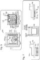
- a well includes a bottom surface, which can be substantially flat or planar, and optionally one or more walls adjacent to and extending upward from the bottom surface (see, for example, Figure 2 , right panel).
- the well also includes at least one inlet and at least one outlet, which can be used to exchange fluids (i.e., liquids and gases) between the well and spaces outside the well.
- an inlet can be used to introduce buffers or reagents into the well or into a gap formed inside the well.
- An outlet can be used to drain liquids from the well or vent gases displaced by liquids introduced into the well.
- Positive or negative pressure can also be applied through an inlet or outlet, for example in the form of an air stream or vacuum.
- Each inlet or outlet includes a hole or aperture in the block frame that opens into the well.
- the hole can be located in the bottom surface of the well or a wall adjacent to the bottom surface, for example.
- the hole can be connected to a microchannel or other passage leading away from the well, for example to a liquid container.
- Inlets and outlets can be positioned in the well as desired.
- multiple inlets are clustered together on the bottom surface of the well, for example within at most 0.1, 0.2, 0.5, 1, 2, or 5 cm 2 of this bottom surface. At least 2, 3, 4, 5, 10, 20, 50, or 100 inlets can be so clustered.
- one or more inlets occur at the edge of the bottom surface of the well, for example at most about 0.1, 0.2, 0.5, 1, 2, 5, or 10 cm from where the bottom surface joins a wall of the well.
- one or more inlets occur near the center of the bottom surface of the well, for example at least about 0.1, 0.2, 0.5, 1, 2, 5, or 10 cm away from where the bottom surface joins a wall of the well.
- one or more outlets can be located at the edge of the bottom surface of the well or near the center.
- an outlet is coupled to a microchannel that is directed downward from the bottom surface of the well. This microchannel can connect to a drain in the block frame and/or a vacuum source, and can lead to the space below the block fame.
- the well can accommodate an assay surface on which a reagent, biological sample, or components thereof can be disposed.
- the assay surface can be on a microscope coverslip, plastic slide, or other object dimensioned to lie flat on the bottom surface of the well, and/or lie parallel to this surface, so that at least one side of the object can be exposed to liquids in the well.
- the object bearing the assay surface can be mechanically secured inside the well, for example using screws or an adhesive, or can rest on the bottom surface of the well or another object. In some embodiments, this object is positioned along the bottom surface of the well so that it lies between the inlets and outlets, and does not overlap them.
- a spacer is placed inside the well along with the assay surface.
- the spacer can be made of rubber, plastic, foam, or another convenient material, and if desired can be affixed to or embedded in the bottom surface of the well.
- the spacer can also be affixed to the assay surface, for example as a rubber gasket running around the perimeter of a microscope coverslip or plastic slide.
- the spacer is used to mediate the height of a gap formed between the assay surface and another surface in the well, and thereby mediate the depth of fluid to which the assay surface is exposed.
- the spacer is mechanically deformable but can be used to establish a gap of consistent height.
- the spacer forms a liquid- or gas-tight seal with another object that it contacts.
- the other object can be the assay surface or the bottom surface of the well, for example.
- the spacer can alternatively be called a "seal" or “sealing.”
- the cartridge also includes a cover.
- the cover can fit inside and/or cover a well formed in the block frame, thereby preventing contaminants from outside the well from contacting liquids in the well or the assay surface.
- the cover can be opened to expose the well.
- the cover is attached to the block frame with a hinge or other mechanism, or simply rests in place on the block frame by friction.
- the cover can also be used to form a gap inside the well adjacent to the assay surface.
- the spacer extends from the bottom surface of the well, upward toward the cover. If the object bearing the assay surface is also disposed on the bottom surface of the well (for example, with one or more pieces of spacer surrounding it), then the spacer can contact the cover (for example, at the outer edges of the cover) when the cover is lowered ( Figure 4 ). The spacer thus leaves a gap between the cover and the assay surface. In this configuration, the assay surface is exposed to the gap and faces upward.
- the spacer is positioned to leave an opening between the cover and the assay surface through which liquid can pass, for example on one side of the gap.
- This opening can occur on the edge of the assay surface nearest the outlet, so that liquid can pass out of the gap between cover and the assay surface and toward the outlet.
- openings occur on both sides of the gap, such that an unobstructed fluidic pathway runs between the inlet(s) and outlet(s) and through the gap.
- the spacer can include two strips of material running parallel to such a pathway.
- the object bearing the assay surface can rest on top of the spacer (for example, the edges of a microscope coverslip can contact the spacer), such that a gap occurs between the assay surface and the bottom surface of the well ( Figure 2 ).
- the cover When the cover is lowered, it can press the object against the spacer, thereby mediating the height of the gap, or restrict the movement of the object in the well.
- the object Another alternative is for the object to be affixed directly to the cover, such that the assay surface and/or the cover contacts the spacer when the cover is lowered, and a gap is formed between the assay surface and the bottom surface of the well.
- the assay surface faces downward, and openings through which liquid can pass can occur (as above) on one or both sides of the gap.
- the spacer extends from the cover downward and is configured to meet the bottom surface of the well when the cover is lowered. In some embodiments, the spacer extends from an outer edge of the cover, for example around the periphery of the cover. Upon lowering the cover over the well, a gap is formed between the cover and the bottom surface of the well.
- an object bearing the assay surface can be placed inside the spacer, for example in the middle of the well. This object can be adjacent to the cover, in which case the assay surface faces downward, or adjacent to the bottom surface of the well, in which case the assay surface faces upward.
- the spacer can be shaped or positioned as desired to leave an opening between the cover and the bottom surface of the well, through which liquid can pass, when the cover is closed. Such an opening can occur on one or both sides of the gap.
- the object bearing the assay surface can be thinner than the spacer in a direction perpendicular to the bottom surface of the well.
- the spacer can be generally configured so that a portion of the gap is open to the space outside the cartridge, and liquid or gas is not prevented from exiting the gap by the spacer.
- the gap between the assay surface and the bottom surface of the well, or between the assay surface and the cover can be at least about 1, 2, 5, 10, 20, 50, 100, 200, 500, or 1000 microns in height.
- the configurations of the block frame, well, assay surface, spacer, and cover can be varied as desired. Some variations are illustrated in Figures 2-8 .
- the well contains a ledge on which the cover can rest, wherein the ledge is elevated above the bottom surface of the well.
- the cover can include downward-facing protrusions to contact the bottom surface of the well, or the edges of the assay surface, when the cover is closed.
- the ledge or protrusions can facilitate the formation of a gap of desired height adjacent to the assay surface.
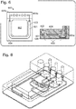
- the cartridge further includes an additional well or a trough adjacent to but separated from the well in which the assay surface is placed ( Figures 6 and 7 ).
- the trough can be disposed in the block frame and can be configured to maintain humidity in the cartridge.
- the trough surrounds the assay well on two or three sides and is separated from the well by a solid barrier.
- the solid barrier can be shorter than the gap formed by any spacer, or taller than this gap, as desired.
- the trough and well can be enclosed by the same openable cover, such that both the trough and well are exposed to the same air sample and humidity can be transferred between the trough and well through the air.
- a liquid such as water can be flowed through the trough, and if desired a separate inlet and outlet can be connected to the trough to regulate the amount of liquid present.
- the bottom surface of the well is sloped or angled to facilitate the flow of liquid in a desired direction, for example from an inlet to an outlet.
- a gap formed between the bottom surface and an assay surface can have non-uniform depth.
- an inlet is located at a site on the bottom surface of the well that is higher than the site for an outlet, so that liquid can flow downhill from the inlet to the outlet.
- an outlet occurring at a low point in the bottom surface of the well serves as or connects to a drain.
- Flow can also be regulated by open grooves or channels cut into the bottom surface of the well, or obstacles to flow (such as bumps or ridges) protruding from the bottom surface.
- the bottom surface of the well is passivated, for example, with a non-stick or hydrophobic coating, to prevent liquids, reagents, or contaminants from adhering to the surface while the cartridge is being used in an assay or is in storage.
- a cartridge as provided herein also includes a plurality of containers embedded in the block frame.
- the containers are configured to store liquids, and deliver liquid to the well through the inlets.
- each container is connected to the well via a microchannel leading to at least one inlet.
- liquid containers can be embedded in the block frame-for example, at least 2, 3, 4, 5, 6, 7, 8, 9, 10, 15, 20, 50, or 100 containers.
- one or more liquid containers has a long axis that is oriented vertically, and is connected at the base of the container to a microchannel leading to the well. Thus, liquid can drain from the container into the well with minimal driving force.
- one or more containers is disposed above the bottom surface of the well, so that liquid can be siphoned from the container into the well.
- the containers are cylindrical in shape.
- Each container can be coupled to one or more pumps, valves, syringes, or other mechanisms to regulate the flow of liquid out of the container.
- the containers can be disposed to one side of the well, as shown in Figures 2-4 and 8.
- the liquid containers can be connected to one or more inlets in the well of the cartridge as desired.
- each container connects to a separate inlet, for example via a microchannel.
- the containers can be equal in number to the inlets, and can be fluidically segregated from each other upstream of the inlets.
- the block frame contains a branched network of microchannels leading from the liquid containers to the inlets.
- one or more microchannels can merge upstream of the inlet, so that liquids carried in these microchannels can mix or travel over the same path before entering the well through a common inlet.
- the microchannels leading from 2, 3, 4, 5, or more liquid containers can thus be connected to the same inlet.
- a microchannel leading from one liquid container can be split into multiple branches, so that liquid from this container can be delivered to multiple inlets in the well.
- One, 2, 3, 4, 5, or more inlets can thus be fed with liquid from the same liquid container.
- Microchannels in the block frame can have any desired dimensions.
- a microchannel can have a width of at least about 1, 10, 100, 1,000, or 10,000 micrometers, or can be dimensioned to allow laminar or turbulent flow.
- the width of a microchannel is at most about 1, 10, 100, 1,000, or 10,000 micrometers.
- the width of a microchannel falls within the range of about 1-10, 1-100, 1-1,000, 1-10,0000, 10-10,000, 100-10,000, 1000-10,000, 10-100, or 100-1,000 micrometers.
- the microchannels disposed in the block frame can all have the same width or can have different widths.
- a microchannel that is used to deliver a liquid to the well in relatively large quantities can be wide, to allow faster delivery, while another microchannel used to deliver liquids in small quantities can be narrow.
- a single microchannel can vary in width along its length to regulate aspects of fluid flow such as flow rate or pressure.
- Microchannels disposed in the block frame can also be coupled to valves or pumps to regulate liquid or gaseous flow.
- a microchannel leading from a liquid container to an inlet in the well can be coupled at either end to a valve or pump (for example, at the outlet of the liquid container, or at the aperture of the inlet), or anywhere along the length of the microchannel.
- a pump or valve coupled to a microchannel is fully contained or embedded in the block frame.
- the microchannels can be bored directly into the block frame, or can be carried by tubing, capillaries, or other conduits through the block frame.
- the cartridge also includes a manifold (see, for example, Figures 2-5 ).
- the manifold can be clamped or otherwise positioned on the block frame adjacent to the liquid containers, and can seal one or more containers from the space outside the cartridge.
- the manifold can contact the block frame using rubber gaskets, O-rings, or other appropriate sealing means.
- the manifold is coupled to a liquid source (for example, in an instrument into which the cartridge is inserted) and is used to supply liquids to one or more containers, for later delivery to the well of the cartridge.
- the manifold can also be coupled to a vacuum or pressure source, and can be used to regulate the flow of liquids into or out of the containers.
- the manifold is coupled to a microchannel in the block frame that leads directly to the well, for example to an inlet or outlet.
- liquids can be delivered directly from the manifold to the well without first passing through a container in the block frame, and/or can be removed from the well to the manifold.
- a channel connecting a manifold or instrument to a well of the cartridge is referred to as a "liquid line,” and in some embodiments is configured to accommodate buffers (e.g., wash fluids) used to displace reagents from the well.
- buffers e.g., wash fluids
- gases can be introduced to or removed from the well via a microchannel coupled directly to the manifold.
- one or more liquid containers are disposed in the cover of the cartridge, as shown in Figure 5 .
- These containers can be used in lieu of or in addition to any containers embedded in the solid block to facilitate fluid flow in the cartridge.
- containers in the cover can be fluidically coupled to the well adjoining the cover.
- a container in the cover can be connected by microchannel to an inlet or outlet in a surface of the cover. This surface, for example a bottom surface of the cover, can be exposed to a gap between the cover and an assay surface.
- one or more liquids for an assay can be introduced through an inlet in the cover rather than an inlet occurring in the bottom surface of the well. Liquids or gases can also be removed through an outlet in the cover.
- a manifold is coupled to the cover to deliver liquids or pressure to one or more containers or microchannels in the cover. Instead or in addition, the manifold can be used to draw a vacuum against a container or microchannel in the cover.
- the cartridge includes one or more inlets in a bottom surface of the cover, and one or more outlets in a bottom surface of the well. In some embodiments, the cartridge includes one or more outlets in a bottom surface of the cover, and one or more inlets in a bottom surface of the well. In some embodiments, at least one inlet and at least one outlet are disposed in a bottom surface of the cover.
- the cartridge can also include a thermal unit underlying the bottom surface of the well.
- the thermal unit can be used to regulate the temperature of assays performed in the cartridge.
- the thermal unit includes a Peltier device and/or a heat sink.
- the bottom surface of the well is thermally conductive.
- the thermal unit can be directly coupled to the block frame of the cartridge, for example with metal screws, plastic screws, or a thermally conductive adhesive.
- the thermal unit can be separated from the block frame by a solid substrate, which can be thermally conductive or insulating.
- the thermal unit can underlie the entire well or a portion thereof (for example, a region near one or more inlets, or a region near one or more outlets).
- the thermal unit can provide or remove heat uniformly over the full area of the bottom surface of the well, or can do so with areal variation or specificity.
- the thermal unit can heat one part of the well while cooling another part, or provide heat to only part of the well while not directly applying heat to the rest of the well.
- the thermal unit can be used to establish temperature gradients across the well.
- a different thermal unit can be associated with each well. These thermal units can be controlled independently, and the wells can be subjected to different thermal protocols.
- the thermal unit can be operated in concert with fluid flow to obtain the desired temperature profile in a well of the cartridge.
- liquid can be flowed through a humidifying trough around the well as discussed above, wherein the liquid is maintained at a different temperature from the thermal unit (see Figure 7 , center panel).
- the center of the well can be heated by the thermal unit while the periphery of the well can be cooled by liquid in the trough, or vice versa.
- liquid or gas can be flowed directly past the thermal unit as shown in Figure 7 , right panel, so that the thermal unit is heated or cooled and the temperature of the well is mediated.
- the presently disclosed cartridges can be used for any biological assay involving a sample or reagent disposed on a substantially flat assay surface, and liquid processing steps.
- Non-limiting examples include immunoassays, other protein-based affinity assays, and nucleic acid hybridization assays.
- the assay surface is coated (directly or indirectly) with antibodies or binding fragments thereof, e.g ., specific for a particular cell type or known analyte.
- the assay surface is coated with protein having a known affinity for a particular cell type or analyte, or with a heterogeneous protein sample.
- the assay surface is coated with cells, e.g ., from an in vitro culture sample, or from a patient sample.
- the assay surface is coated (directly or indirectly) with primers or probes that will specifically hybridize to a known sequence, or with a heterogeneous nucleic acid sample.
- Immunoassays that can be carried out on the presently disclosed cartridges include, for example, enzyme linked immunoabsorbent assay (ELISA), fluorescent immunosorbent assay (FIA), immunohistochemistry, chemical linked immunosorbent assay (CLIA), radioimmuno assay (RIA), competitive and non-competitive assay systems, e.g ., "sandwich” immunoassays, immunoprecipitation assays, precipitin reactions, immunodiffusion assays, immunoradiometric assays, fluorescent immunoassays, etc.
- ELISA enzyme linked immunoabsorbent assay
- FFIA fluorescent immunosorbent assay
- CLIA chemical linked immunosorbent assay
- RIA radioimmuno assay
- competitive and non-competitive assay systems e.g ., "sandwich” immunoassays, immunoprecipitation assays, precipitin reactions, immunodiffusion assays, immunoradiometric assays, fluorescent immunoassay
- the ELISAs include a number of variations.
- the ELISA comprises preparing a sample that potentially includes an antigen, coating the coverslip or other matrix material with the sample, adding primary antibody, incubating for a period of time, washing away unbound material, adding labeled secondary antibody, incubating, and washing.
- One of skill in the art would be knowledgeable as to other variations of ELISAs, e.g ., where target is labeled and the primary antibody is coated on the matrix material, etc.
- Immunoprecipitation and immunoseparation protocols can comprise contacting a sample with primary antibody specific for the desired target in the sample, incubating for a period of time (e.g. , 1-4 hours at 4°C), optionally adding secondary antibody for detection, and incubating, washing, and recovering the target in an SDS/sample buffer or elution buffer.
- a period of time e.g. , 1-4 hours at 4°C
- the assay involves a cell sample, e.g., cells grown on the assay surface.
- the cells on the assay surface can be exposed to a first reagent that binds a cell surface marker, washed, exposed to a second reagent that binds a different cell surface marker, or that binds to the first reagent, washed, exposed to a third reagent that, e.g ., binds the first and/or second reagent and can be detected, washed, etc.
- the assay surface e.g ., coverslip
- the presently disclosed cartridges can be used for nucleic acid hybridization assays, e.g ., to detect expression levels, genetic variants, or single nucleic acid polymorphisms (SNPs).
- Methods for detection include nucleotide arrays (e.g ., a homologous or heterogeneous population of nucleic acid primers or probes disposed on the assay surface), sequencing, and amplification methods, etc.
- Primers or probes are designed to hybridize to a target sequence. For example, genomic DNA can be screened for the presence of an identified genetic element of using a probe based upon one or more sequences, e.g ., using a probe with substantial identity to a subsequence of a targeted gene. Expressed RNA can also be screened for sequence and/or quantity.
- a probe can be between 10-500 nucleotides in length, e.g ., 10-100, 10-40, 10-20, 20-100, 100-400, etc.
- the sequence to be detected includes 8 contiguous nucleotides, e.g ., at least 10, 15, 20, 25, 30, 35 or more contiguous nucleotides of a known sequence.
- the assay can be varied for stringency, to allow binding of only 100% complementary sequences of a given length, or less than 100%. As the conditions for hybridization become more stringent, there must be a greater degree of complementarity between the probe and the target for duplex formation to occur. Thus, high stringency conditions are typically used for detecting a SNP.
- the degree of stringency can be controlled by temperature, ionic strength, pH and/or the presence of a partially denaturing solvent such as formamide in the buffer.
- the stringency of hybridization is conveniently varied by changing the concentration of formamide within the range up to and about 50%.
- the degree of complementarity (sequence identity) required for detectable binding will vary in accordance with the stringency of the hybridization medium and/or wash medium. In certain embodiments, in particular for detection of a particular SNP, the degree of complementarity is about 100 percent. In other embodiments, sequence variations can result in ⁇ 100% complementarity, ⁇ 90% complementarity probes, ⁇ 80% complementarity probes, etc., in particular, in a sequence that does not involve a SNP. In some examples, e.g ., detection of species homologs, primers may be compensated for by reducing the stringency of the hybridization and/or wash medium.
- wash or incubation conditions may include low salt and/or high temperature, such as provided by about 0.02 M to about 0.15 M NaCl at temperatures of about 50°C to about 70°C.
- the temperature and ionic strength of a desired stringency are determined in part by the length of the particular nucleic acid(s), the length and nucleotide content of the target sequence(s), the charge composition of the nucleic acid(s), and by the presence or concentration of formamide, tetramethylammonium chloride or other solvent(s) in a hybridization mixture.
- nucleic acids of interest can also be amplified using a variety of known amplification techniques, For instance, polymerase chain reaction (PCR) technology may be used to amplify target sequences directly from DNA, RNA, or cDNA.
- PCR polymerase chain reaction
- the assay surface is coated with a primer that hybridizes to the target sequence, and the reagents can include amplification regents, e.g ., an opposing complementary primer, polymerase, buffers, etc.
- amplification regents e.g ., an opposing complementary primer, polymerase, buffers, etc.
- kits that include the presently disclosed assay cartridges.
- a cartridge can be included with a kit that further includes reagents and components for common clinical or research assays.
- the kit includes a cartridge with containers pre-filled with assay reagents.
- the kit includes a cartridge and assay reagents in separate containers to be added to the cartridge to carry out the desired assay.
- the kit farther includes wash or buffer solutions (e.g. , concentrated stock solutions, or dry buffer components for hydration).
- the kit includes a plurality of coverslips, e.g. , as a supply to be coated with sample or reagent by the user.
- the kit includes controls for the assay (e.g ., a coverslip known to be positive or negative for the targeted analyte).
- nucleic acids of interest can also be amplified using a variety of known amplification techniques.
- PCR polymerase chain reaction
- the assay surface is coated with a primer that hybridizes to the target sequence, and the reagents can include amplification regents, e.g. , an opposing complementary primer, polymerase, buffers, etc.
- amplification regents e.g. , an opposing complementary primer, polymerase, buffers, etc.
- kits that include the presently disclosed assay cartridges.
- a cartridge can be included with a kit that further includes reagents and components for common clinical or research assays.
- the kit includes a cartridge with containers pre-filled with assay reagents.
- the kit includes a cartridge and assay reagents in separate containers to be added to the cartridge to carry out the desired assay.
- the kit further includes wash or buffer solutions (e.g. , concentrated stock solutions, or dry buffer components for hydration).
- the kit includes a plurality of coverslips, e.g ., as a supply to be coated with sample or reagent by the user.
- the kit includes controls for the assay (e.g ., a coverslip known to be positive or negative for the targeted analyte).
Landscapes
- Chemical & Material Sciences (AREA)
- Health & Medical Sciences (AREA)
- Life Sciences & Earth Sciences (AREA)
- Engineering & Computer Science (AREA)
- Immunology (AREA)
- General Health & Medical Sciences (AREA)
- Molecular Biology (AREA)
- Organic Chemistry (AREA)
- Analytical Chemistry (AREA)
- Proteomics, Peptides & Aminoacids (AREA)
- Biochemistry (AREA)
- Zoology (AREA)
- Hematology (AREA)
- Wood Science & Technology (AREA)
- Microbiology (AREA)
- Biotechnology (AREA)
- Physics & Mathematics (AREA)
- Chemical Kinetics & Catalysis (AREA)
- Clinical Laboratory Science (AREA)
- Urology & Nephrology (AREA)
- Biomedical Technology (AREA)
- Bioinformatics & Cheminformatics (AREA)
- Genetics & Genomics (AREA)
- General Engineering & Computer Science (AREA)
- Biophysics (AREA)
- Cell Biology (AREA)
- Food Science & Technology (AREA)
- Medicinal Chemistry (AREA)
- General Physics & Mathematics (AREA)
- Pathology (AREA)
- Dispersion Chemistry (AREA)
- Apparatus Associated With Microorganisms And Enzymes (AREA)
- Measuring Or Testing Involving Enzymes Or Micro-Organisms (AREA)
Claims (15)
- Cartouche comprenant :une armature en bloc comprenant(a) un puits, le puits comportant une sortie, au moins une entrée, et une surface inférieure ;(b) une pluralité de conteneurs imbriqués dans l'armature en bloc, chaque conteneur étant connecté au puits via un micro-canal menant vers ladite au moins une entrée ; et(c) une rigole séparée du puits et l'entourant, ladite rigole étant configurée pour retenir un liquide ; etun capot ouvrable, ledit capot une fois fermé étant configuré pour enfermer une surface d'essai et former un espace entre (i) la surface d'essai et la surface inférieure du puits, ou (ii) la surface d'essai et le capot.
- Cartouche de la revendication 1, dans laquelle(i) la sortie part de la surface inférieure du puits ; ou(ii) ladite au moins une entrée mène vers la surface inférieure du puits ; ou(iii) la sortie est configurée pour être attachée à une ligne de vide.
- Cartouche de la revendication 1, dans laquelle l'espace est formé par une entretoise, l'entretoise s'étendant depuis la surface inférieure du puits et étant configurée pour rencontrer le capot ou la surface d'essai sur le bord extérieur du capot ou de la surface d'essai, retient le capot ou la surface d'essai parallèlement à la surface inférieure du puits, et laisse une ouverture entre le capot ou la surface d'essai et la surface inférieure du puits, à travers laquelle du liquide peut passer.
- Cartouche de la revendication 1, dans laquelle l'espace est formé par une entretoise, l'entretoise s'étendant depuis le bord extérieur du capot, et étant configurée pour rencontrer la surface inférieure du puits et laisser une ouverture entre le capot et la surface inférieure, à travers laquelle du liquide peut passer lorsque le capot est fermé, et de préférence la surface d'essai, lorsqu'elle est présente, est placée à l'intérieur de l'entretoise sur la surface inférieure du puits.
- Cartouche de la revendication 1, dans laquelle l'espace entre la surface d'essai et la surface inférieure du puits ou entre la surface d'essai et le capot retient un volume de 100 µl ou moins.
- Cartouche selon la revendication 1, dans laquelle(i) la cartouche est attachée à une rampe de distribution pour sceller la pluralité de conteneurs ; ou(ii) chaque conteneur de la pluralité de conteneurs est configuré pour être relié à une ligne de pression ou de liquide ; ou(iii) chaque conteneur de la pluralité de conteneurs est attaché à un canal d'entrée actionné par une valve ; ou(iv) chaque conteneur de la pluralité de conteneurs retient un réactif d'essai ou un tampon ; ou(v) chaque conteneur de la pluralité de conteneurs est connecté au puits via un micro-canal qui mène vers une entrée séparée ; ou(vi) l'armature en bloc se compose d'un polymère, de silicium, de métal, de verre ou de céramique ; ou(vii) les conteneurs sont disposés sur un côté du puits.
- Cartouche de la revendication 1, comprenant en outre la surface d'essai, et de préférence(i) la surface d'essai présente une surface de 80-2500 mm2 ; ou(ii) la surface d'essai fait face à l'espace et est revêtue de cellules, d'anticorps, de protéines ou d'acides nucléiques.
- Cartouche de la revendication 1, comprenant en outre(i) un élément thermique se trouvant sous la surface inférieure du puits ; ou(ii) au moins un conteneur imbriqué dans le capot.
- Méthode d'essai automatisée, comprenant les étapes de placement d'une surface d'essai dans la cartouche de la revendication 1 et fermeture du capot ;
distribution d'un premier réactif depuis l'un des conteneurs de la pluralité de conteneurs dans le puits de façon à ce que le premier réactif pénètre dans l'espace entre la surface d'essai et la surface inférieure du puits ou entre la surface d'essai et le capot ;
distribution d'un fluide de lavage depuis l'un des conteneurs de la pluralité de conteneurs ou depuis une ligne de liquide dans le puits, de façon à ce que le fluide de lavage déplace le premier réactif de l'espace ;
distribution d'un second réactif depuis l'un des conteneurs de la pluralité de conteneurs dans le puits de façon à ce que le second réactif pénètre dans l'espace entre la surface d'essai et la surface inférieure du puits ou entre la surface d'essai et le capot ; et
distribution du fluide de lavage depuis l'un des conteneurs de la pluralité de conteneurs ou depuis une ligne de liquide vers le puits de façon telle que le fluide de lavage déplace le second réactif de l'espace. - Procédé de la revendication 9, comprenant en outre les étapes de(i) retrait de la surface d'essai depuis la cartouche après une étape de lavage finale, et détection d'un résultat de l'essai ; ou(ii) réalisation d'au moins un cycle supplémentaire de distribution de réactif et de lavage.
- Procédé de la revendication 9, dans lequel(i) l'essai est un immunoessai ; ou(ii) est un essai d'hybridation d'acide nucléique.
- Procédé de la revendication 9, dans lequel les premier et second réactifs sont déplacés via une ouverture entre la surface d'essai et le capot ou entre la surface d'essai et la surface inférieure du puits.
- Procédé de la revendication 9, dans lequel la distribution comprend l'application de pression au conteneur depuis lequel le réactif ou le fluide de lavage est distribué.
- Procédé de la revendication 9, comprenant en outre l'application d'un vide depuis la sortie faisant suite à chaque étape de distribution.
- Procédé selon la revendication 9, dans lequel le fluide de lavage est distribué depuis l'extérieur de la cartouche dans le puits par l'intermédiaire d'un micro-canal.
Applications Claiming Priority (2)
| Application Number | Priority Date | Filing Date | Title |
|---|---|---|---|
| US201461981617P | 2014-04-18 | 2014-04-18 | |
| PCT/US2015/026502 WO2015161275A1 (fr) | 2014-04-18 | 2015-04-17 | Dispositifs microfluidiques pour dosages automatisés |
Publications (3)
| Publication Number | Publication Date |
|---|---|
| EP2988872A1 EP2988872A1 (fr) | 2016-03-02 |
| EP2988872A4 EP2988872A4 (fr) | 2016-11-09 |
| EP2988872B1 true EP2988872B1 (fr) | 2018-06-13 |
Family
ID=54321827
Family Applications (1)
| Application Number | Title | Priority Date | Filing Date |
|---|---|---|---|
| EP15780234.9A Not-in-force EP2988872B1 (fr) | 2014-04-18 | 2015-04-17 | Dispositifs microfluidiques pour dosages automatisés |
Country Status (4)
| Country | Link |
|---|---|
| US (1) | US9983205B2 (fr) |
| EP (1) | EP2988872B1 (fr) |
| CN (1) | CN105339087B (fr) |
| WO (1) | WO2015161275A1 (fr) |
Families Citing this family (11)
| Publication number | Priority date | Publication date | Assignee | Title |
|---|---|---|---|---|
| RU2643937C2 (ru) | 2012-06-28 | 2018-02-06 | Флюоресентрик, Инк. | Устройство для обнаружения химического индикатора |
| CN113791203B (zh) * | 2015-06-12 | 2024-05-17 | 芯易诊有限公司 | 用于分析生物样品的方法 |
| CN105154323B (zh) * | 2015-08-14 | 2017-08-29 | 深圳市瀚海基因生物科技有限公司 | 一种单分子测序芯片 |
| BR112018008629B1 (pt) * | 2015-11-04 | 2020-11-17 | Nitto Denko Corporation | aparelho para ensaio de um biofluido, aparelho para contenção e dispensa de amostras de biofluido e sistema para dispensa e ensaio de biofluido |
| US10882040B2 (en) * | 2015-11-30 | 2021-01-05 | Rqmicro Ag | Interface component for a microfluidic device, assemblies, and method for extracting particles from a sample |
| GB2561994B (en) * | 2015-12-04 | 2021-12-01 | Harvard College | Open-top microfluidic devices and methods for simulating a function of a tissue |
| CN110998324B (zh) * | 2017-02-08 | 2025-03-28 | 上海宜晟生物科技有限公司 | 数字测定 |
| US11207685B2 (en) * | 2017-02-13 | 2021-12-28 | Bio-Rad Laboratories, Inc. | System, method, and device for forming an array of emulsions |
| TWI695162B (zh) * | 2017-09-28 | 2020-06-01 | 美商伊路米納有限公司 | 流體施配器總成與用於將流體施配至流體匣中的方法 |
| WO2019108412A1 (fr) * | 2017-11-28 | 2019-06-06 | Bio-Rad Laboratories, Inc. | Dispositif de dosage à écoulement latéral |
| AU2019408268B2 (en) * | 2018-12-20 | 2024-08-22 | Leica Biosystems Melbourne Pty Ltd | A slide output module |
Family Cites Families (15)
| Publication number | Priority date | Publication date | Assignee | Title |
|---|---|---|---|---|
| US4963498A (en) * | 1985-08-05 | 1990-10-16 | Biotrack | Capillary flow device |
| US5399486A (en) * | 1993-02-18 | 1995-03-21 | Biocircuits Corporation | Disposable unit in diagnostic assays |
| US5356525A (en) * | 1993-04-16 | 1994-10-18 | Beckman Instruments, Inc. | Sample handling system |
| US6673620B1 (en) | 1999-04-20 | 2004-01-06 | Cytologix Corporation | Fluid exchange in a chamber on a microscope slide |
| DE102004027422A1 (de) * | 2004-06-04 | 2005-12-29 | Boehringer Ingelheim Microparts Gmbh | Vorrichtung zur Aufnahme von Blut und Abtrennung von Blutbestandteilen |
| US9056291B2 (en) * | 2005-11-30 | 2015-06-16 | Micronics, Inc. | Microfluidic reactor system |
| US7976795B2 (en) | 2006-01-19 | 2011-07-12 | Rheonix, Inc. | Microfluidic systems |
| US8974748B2 (en) | 2007-04-05 | 2015-03-10 | Corning Incorporated | Dual inlet microchannel device and method for using same |
| GB0618966D0 (en) * | 2006-09-26 | 2006-11-08 | Iti Scotland Ltd | Cartridge system |
| US8122901B2 (en) | 2008-06-30 | 2012-02-28 | Canon U.S. Life Sciences, Inc. | System and method for microfluidic flow control |
| US9321051B2 (en) | 2009-12-22 | 2016-04-26 | Samsung Electronics Co., Ltd. | Microfluidic device and method of manufacturing the same |
| WO2012075263A1 (fr) * | 2010-12-03 | 2012-06-07 | Abbott Point Of Care Inc. | Dispositifs d'analyse avec dilution d'échantillon et vérification de dilution intégrées et leurs procédés d'utilisation |
| US9377439B2 (en) | 2011-11-25 | 2016-06-28 | Tecan Trading Ag | Disposable cartridge for microfluidics system |
| CN104136123B (zh) | 2012-01-09 | 2017-03-01 | 精密公司 | 微流体反应器系统 |
| US9580679B2 (en) * | 2012-09-21 | 2017-02-28 | California Institute Of Technology | Methods and devices for sample lysis |
-
2015
- 2015-04-17 EP EP15780234.9A patent/EP2988872B1/fr not_active Not-in-force
- 2015-04-17 WO PCT/US2015/026502 patent/WO2015161275A1/fr not_active Ceased
- 2015-04-17 CN CN201580000874.XA patent/CN105339087B/zh not_active Expired - Fee Related
- 2015-04-17 US US14/689,791 patent/US9983205B2/en active Active
Non-Patent Citations (1)
| Title |
|---|
| None * |
Also Published As
| Publication number | Publication date |
|---|---|
| EP2988872A1 (fr) | 2016-03-02 |
| CN105339087B (zh) | 2019-07-26 |
| WO2015161275A1 (fr) | 2015-10-22 |
| US9983205B2 (en) | 2018-05-29 |
| US20150301033A1 (en) | 2015-10-22 |
| EP2988872A4 (fr) | 2016-11-09 |
| CN105339087A (zh) | 2016-02-17 |
Similar Documents
| Publication | Publication Date | Title |
|---|---|---|
| EP2988872B1 (fr) | Dispositifs microfluidiques pour dosages automatisés | |
| US7833804B2 (en) | Structure for introducing a plurality of solutions, micro fluidic device having said structure and method for introducing solution | |
| US6558944B1 (en) | High throughput screening assay systems in microscale fluidic devices | |
| Liu et al. | Multichannel PCR-CE microdevice for genetic analysis | |
| KR101216828B1 (ko) | 병원균 검출과 분석을 위한 방법과 기구 | |
| US7754150B2 (en) | Microfluidic analytic detection assays, devices, and integrated systems | |
| US8808647B2 (en) | Multi-well plate with tailored chambers | |
| US8263022B2 (en) | Microfluidic detection of analytes | |
| US20090062134A1 (en) | Assay imaging apparatus and methods | |
| WO2000063704A2 (fr) | Appareil et procedes d'analyse d'echantillons | |
| US20100279309A1 (en) | Microfluidic chips and systems for analyzing protein expression, and methods of use thereof | |
| US20180015470A1 (en) | Microfluidics based fetal cell detection and isolation for non-invasive prenatal testing | |
| Zhuang et al. | Recent advances in integrated microfluidics for liquid biopsies and future directions | |
| US20080020453A1 (en) | Analytical system based on porous material for highly parallel single cell detection | |
| Kinpara et al. | A picoliter chamber array for cell-free protein synthesis | |
| WO2008122241A1 (fr) | Analyses rapides de protéines et dispositif associé | |
| JP2009507223A (ja) | 複合体の形成方法及び分離方法 | |
| EP3052614B1 (fr) | Procédé d'enrichissement ou d'isolation d'une population de cellules cibles | |
| US20160341694A1 (en) | Method and apparatus to concentrate and detect an analyte in a sample | |
| Ouellet et al. | Multiplexed surface plasmon resonance imaging for protein biomarker analysis | |
| US8980621B2 (en) | High-density multiwell-plate | |
| Pinto et al. | Microfluidic Cartridge for Bead-Based Affinity Assays | |
| CN1355884A (zh) | 涉及聚离子的荧光偏振试验 | |
| Yu et al. | The Polymorphism of SMIM1 Gene in Chinese Dividuals | |
| Kaigala et al. | Rapid Detection of Multiple Myeloma using a microfluidic platform |
Legal Events
| Date | Code | Title | Description |
|---|---|---|---|
| PUAI | Public reference made under article 153(3) epc to a published international application that has entered the european phase |
Free format text: ORIGINAL CODE: 0009012 |
|
| 17P | Request for examination filed |
Effective date: 20151118 |
|
| AK | Designated contracting states |
Kind code of ref document: A1 Designated state(s): AL AT BE BG CH CY CZ DE DK EE ES FI FR GB GR HR HU IE IS IT LI LT LU LV MC MK MT NL NO PL PT RO RS SE SI SK SM TR |
|
| AX | Request for extension of the european patent |
Extension state: BA ME |
|
| A4 | Supplementary search report drawn up and despatched |
Effective date: 20161007 |
|
| RIC1 | Information provided on ipc code assigned before grant |
Ipc: G01N 33/543 20060101ALI20161003BHEP Ipc: C12Q 1/68 20060101ALI20161003BHEP Ipc: B01L 3/00 20060101AFI20161003BHEP Ipc: B01L 7/00 20060101ALI20161003BHEP |
|
| DAV | Request for validation of the european patent (deleted) | ||
| DAX | Request for extension of the european patent (deleted) | ||
| GRAP | Despatch of communication of intention to grant a patent |
Free format text: ORIGINAL CODE: EPIDOSNIGR1 |
|
| STAA | Information on the status of an ep patent application or granted ep patent |
Free format text: STATUS: GRANT OF PATENT IS INTENDED |
|
| INTG | Intention to grant announced |
Effective date: 20171206 |
|
| GRAS | Grant fee paid |
Free format text: ORIGINAL CODE: EPIDOSNIGR3 |
|
| GRAA | (expected) grant |
Free format text: ORIGINAL CODE: 0009210 |
|
| STAA | Information on the status of an ep patent application or granted ep patent |
Free format text: STATUS: THE PATENT HAS BEEN GRANTED |
|
| AK | Designated contracting states |
Kind code of ref document: B1 Designated state(s): AL AT BE BG CH CY CZ DE DK EE ES FI FR GB GR HR HU IE IS IT LI LT LU LV MC MK MT NL NO PL PT RO RS SE SI SK SM TR |
|
| REG | Reference to a national code |
Ref country code: GB Ref legal event code: FG4D |
|
| REG | Reference to a national code |
Ref country code: CH Ref legal event code: EP Ref country code: AT Ref legal event code: REF Ref document number: 1007919 Country of ref document: AT Kind code of ref document: T Effective date: 20180615 |
|
| REG | Reference to a national code |
Ref country code: IE Ref legal event code: FG4D |
|
| REG | Reference to a national code |
Ref country code: DE Ref legal event code: R096 Ref document number: 602015012372 Country of ref document: DE |
|
| REG | Reference to a national code |
Ref country code: NL Ref legal event code: MP Effective date: 20180613 |
|
| REG | Reference to a national code |
Ref country code: LT Ref legal event code: MG4D |
|
| PG25 | Lapsed in a contracting state [announced via postgrant information from national office to epo] |
Ref country code: ES Free format text: LAPSE BECAUSE OF FAILURE TO SUBMIT A TRANSLATION OF THE DESCRIPTION OR TO PAY THE FEE WITHIN THE PRESCRIBED TIME-LIMIT Effective date: 20180613 Ref country code: LT Free format text: LAPSE BECAUSE OF FAILURE TO SUBMIT A TRANSLATION OF THE DESCRIPTION OR TO PAY THE FEE WITHIN THE PRESCRIBED TIME-LIMIT Effective date: 20180613 Ref country code: CY Free format text: LAPSE BECAUSE OF FAILURE TO SUBMIT A TRANSLATION OF THE DESCRIPTION OR TO PAY THE FEE WITHIN THE PRESCRIBED TIME-LIMIT Effective date: 20180613 Ref country code: SE Free format text: LAPSE BECAUSE OF FAILURE TO SUBMIT A TRANSLATION OF THE DESCRIPTION OR TO PAY THE FEE WITHIN THE PRESCRIBED TIME-LIMIT Effective date: 20180613 Ref country code: BG Free format text: LAPSE BECAUSE OF FAILURE TO SUBMIT A TRANSLATION OF THE DESCRIPTION OR TO PAY THE FEE WITHIN THE PRESCRIBED TIME-LIMIT Effective date: 20180913 Ref country code: NO Free format text: LAPSE BECAUSE OF FAILURE TO SUBMIT A TRANSLATION OF THE DESCRIPTION OR TO PAY THE FEE WITHIN THE PRESCRIBED TIME-LIMIT Effective date: 20180913 Ref country code: FI Free format text: LAPSE BECAUSE OF FAILURE TO SUBMIT A TRANSLATION OF THE DESCRIPTION OR TO PAY THE FEE WITHIN THE PRESCRIBED TIME-LIMIT Effective date: 20180613 |
|
| PG25 | Lapsed in a contracting state [announced via postgrant information from national office to epo] |
Ref country code: HR Free format text: LAPSE BECAUSE OF FAILURE TO SUBMIT A TRANSLATION OF THE DESCRIPTION OR TO PAY THE FEE WITHIN THE PRESCRIBED TIME-LIMIT Effective date: 20180613 Ref country code: GR Free format text: LAPSE BECAUSE OF FAILURE TO SUBMIT A TRANSLATION OF THE DESCRIPTION OR TO PAY THE FEE WITHIN THE PRESCRIBED TIME-LIMIT Effective date: 20180914 Ref country code: LV Free format text: LAPSE BECAUSE OF FAILURE TO SUBMIT A TRANSLATION OF THE DESCRIPTION OR TO PAY THE FEE WITHIN THE PRESCRIBED TIME-LIMIT Effective date: 20180613 Ref country code: RS Free format text: LAPSE BECAUSE OF FAILURE TO SUBMIT A TRANSLATION OF THE DESCRIPTION OR TO PAY THE FEE WITHIN THE PRESCRIBED TIME-LIMIT Effective date: 20180613 |
|
| REG | Reference to a national code |
Ref country code: AT Ref legal event code: MK05 Ref document number: 1007919 Country of ref document: AT Kind code of ref document: T Effective date: 20180613 |
|
| PG25 | Lapsed in a contracting state [announced via postgrant information from national office to epo] |
Ref country code: NL Free format text: LAPSE BECAUSE OF FAILURE TO SUBMIT A TRANSLATION OF THE DESCRIPTION OR TO PAY THE FEE WITHIN THE PRESCRIBED TIME-LIMIT Effective date: 20180613 |
|
| PG25 | Lapsed in a contracting state [announced via postgrant information from national office to epo] |
Ref country code: SK Free format text: LAPSE BECAUSE OF FAILURE TO SUBMIT A TRANSLATION OF THE DESCRIPTION OR TO PAY THE FEE WITHIN THE PRESCRIBED TIME-LIMIT Effective date: 20180613 Ref country code: RO Free format text: LAPSE BECAUSE OF FAILURE TO SUBMIT A TRANSLATION OF THE DESCRIPTION OR TO PAY THE FEE WITHIN THE PRESCRIBED TIME-LIMIT Effective date: 20180613 Ref country code: CZ Free format text: LAPSE BECAUSE OF FAILURE TO SUBMIT A TRANSLATION OF THE DESCRIPTION OR TO PAY THE FEE WITHIN THE PRESCRIBED TIME-LIMIT Effective date: 20180613 Ref country code: PL Free format text: LAPSE BECAUSE OF FAILURE TO SUBMIT A TRANSLATION OF THE DESCRIPTION OR TO PAY THE FEE WITHIN THE PRESCRIBED TIME-LIMIT Effective date: 20180613 Ref country code: AT Free format text: LAPSE BECAUSE OF FAILURE TO SUBMIT A TRANSLATION OF THE DESCRIPTION OR TO PAY THE FEE WITHIN THE PRESCRIBED TIME-LIMIT Effective date: 20180613 Ref country code: EE Free format text: LAPSE BECAUSE OF FAILURE TO SUBMIT A TRANSLATION OF THE DESCRIPTION OR TO PAY THE FEE WITHIN THE PRESCRIBED TIME-LIMIT Effective date: 20180613 Ref country code: IS Free format text: LAPSE BECAUSE OF FAILURE TO SUBMIT A TRANSLATION OF THE DESCRIPTION OR TO PAY THE FEE WITHIN THE PRESCRIBED TIME-LIMIT Effective date: 20181013 |
|
| PG25 | Lapsed in a contracting state [announced via postgrant information from national office to epo] |
Ref country code: IT Free format text: LAPSE BECAUSE OF FAILURE TO SUBMIT A TRANSLATION OF THE DESCRIPTION OR TO PAY THE FEE WITHIN THE PRESCRIBED TIME-LIMIT Effective date: 20180613 Ref country code: SM Free format text: LAPSE BECAUSE OF FAILURE TO SUBMIT A TRANSLATION OF THE DESCRIPTION OR TO PAY THE FEE WITHIN THE PRESCRIBED TIME-LIMIT Effective date: 20180613 |
|
| REG | Reference to a national code |
Ref country code: DE Ref legal event code: R097 Ref document number: 602015012372 Country of ref document: DE |
|
| PLBE | No opposition filed within time limit |
Free format text: ORIGINAL CODE: 0009261 |
|
| STAA | Information on the status of an ep patent application or granted ep patent |
Free format text: STATUS: NO OPPOSITION FILED WITHIN TIME LIMIT |
|
| 26N | No opposition filed |
Effective date: 20190314 |
|
| PG25 | Lapsed in a contracting state [announced via postgrant information from national office to epo] |
Ref country code: DK Free format text: LAPSE BECAUSE OF FAILURE TO SUBMIT A TRANSLATION OF THE DESCRIPTION OR TO PAY THE FEE WITHIN THE PRESCRIBED TIME-LIMIT Effective date: 20180613 Ref country code: SI Free format text: LAPSE BECAUSE OF FAILURE TO SUBMIT A TRANSLATION OF THE DESCRIPTION OR TO PAY THE FEE WITHIN THE PRESCRIBED TIME-LIMIT Effective date: 20180613 |
|
| PG25 | Lapsed in a contracting state [announced via postgrant information from national office to epo] |
Ref country code: AL Free format text: LAPSE BECAUSE OF FAILURE TO SUBMIT A TRANSLATION OF THE DESCRIPTION OR TO PAY THE FEE WITHIN THE PRESCRIBED TIME-LIMIT Effective date: 20180613 |
|
| REG | Reference to a national code |
Ref country code: CH Ref legal event code: PL |
|
| REG | Reference to a national code |
Ref country code: BE Ref legal event code: MM Effective date: 20190430 |
|
| PG25 | Lapsed in a contracting state [announced via postgrant information from national office to epo] |
Ref country code: LU Free format text: LAPSE BECAUSE OF NON-PAYMENT OF DUE FEES Effective date: 20190417 Ref country code: MC Free format text: LAPSE BECAUSE OF FAILURE TO SUBMIT A TRANSLATION OF THE DESCRIPTION OR TO PAY THE FEE WITHIN THE PRESCRIBED TIME-LIMIT Effective date: 20180613 |
|
| PG25 | Lapsed in a contracting state [announced via postgrant information from national office to epo] |
Ref country code: LI Free format text: LAPSE BECAUSE OF NON-PAYMENT OF DUE FEES Effective date: 20190430 Ref country code: CH Free format text: LAPSE BECAUSE OF NON-PAYMENT OF DUE FEES Effective date: 20190430 |
|
| PG25 | Lapsed in a contracting state [announced via postgrant information from national office to epo] |
Ref country code: BE Free format text: LAPSE BECAUSE OF NON-PAYMENT OF DUE FEES Effective date: 20190430 |
|
| PG25 | Lapsed in a contracting state [announced via postgrant information from national office to epo] |
Ref country code: TR Free format text: LAPSE BECAUSE OF FAILURE TO SUBMIT A TRANSLATION OF THE DESCRIPTION OR TO PAY THE FEE WITHIN THE PRESCRIBED TIME-LIMIT Effective date: 20180613 |
|
| PG25 | Lapsed in a contracting state [announced via postgrant information from national office to epo] |
Ref country code: IE Free format text: LAPSE BECAUSE OF NON-PAYMENT OF DUE FEES Effective date: 20190417 |
|
| PG25 | Lapsed in a contracting state [announced via postgrant information from national office to epo] |
Ref country code: PT Free format text: LAPSE BECAUSE OF FAILURE TO SUBMIT A TRANSLATION OF THE DESCRIPTION OR TO PAY THE FEE WITHIN THE PRESCRIBED TIME-LIMIT Effective date: 20181015 |
|
| PG25 | Lapsed in a contracting state [announced via postgrant information from national office to epo] |
Ref country code: HU Free format text: LAPSE BECAUSE OF FAILURE TO SUBMIT A TRANSLATION OF THE DESCRIPTION OR TO PAY THE FEE WITHIN THE PRESCRIBED TIME-LIMIT; INVALID AB INITIO Effective date: 20150417 Ref country code: MT Free format text: LAPSE BECAUSE OF FAILURE TO SUBMIT A TRANSLATION OF THE DESCRIPTION OR TO PAY THE FEE WITHIN THE PRESCRIBED TIME-LIMIT Effective date: 20180613 |
|
| PG25 | Lapsed in a contracting state [announced via postgrant information from national office to epo] |
Ref country code: MK Free format text: LAPSE BECAUSE OF FAILURE TO SUBMIT A TRANSLATION OF THE DESCRIPTION OR TO PAY THE FEE WITHIN THE PRESCRIBED TIME-LIMIT Effective date: 20180613 |
|
| P01 | Opt-out of the competence of the unified patent court (upc) registered |
Effective date: 20230510 |
|
| PGFP | Annual fee paid to national office [announced via postgrant information from national office to epo] |
Ref country code: FR Payment date: 20230421 Year of fee payment: 9 Ref country code: DE Payment date: 20230427 Year of fee payment: 9 |
|
| PGFP | Annual fee paid to national office [announced via postgrant information from national office to epo] |
Ref country code: GB Payment date: 20230418 Year of fee payment: 9 |
|
| REG | Reference to a national code |
Ref country code: DE Ref legal event code: R119 Ref document number: 602015012372 Country of ref document: DE |
|
| GBPC | Gb: european patent ceased through non-payment of renewal fee |
Effective date: 20240417 |
|
| PG25 | Lapsed in a contracting state [announced via postgrant information from national office to epo] |
Ref country code: DE Free format text: LAPSE BECAUSE OF NON-PAYMENT OF DUE FEES Effective date: 20241105 |
|
| PG25 | Lapsed in a contracting state [announced via postgrant information from national office to epo] |
Ref country code: GB Free format text: LAPSE BECAUSE OF NON-PAYMENT OF DUE FEES Effective date: 20240417 |
|
| PG25 | Lapsed in a contracting state [announced via postgrant information from national office to epo] |
Ref country code: FR Free format text: LAPSE BECAUSE OF NON-PAYMENT OF DUE FEES Effective date: 20240430 |
|
| PG25 | Lapsed in a contracting state [announced via postgrant information from national office to epo] |
Ref country code: GB Free format text: LAPSE BECAUSE OF NON-PAYMENT OF DUE FEES Effective date: 20240417 Ref country code: FR Free format text: LAPSE BECAUSE OF NON-PAYMENT OF DUE FEES Effective date: 20240430 Ref country code: DE Free format text: LAPSE BECAUSE OF NON-PAYMENT OF DUE FEES Effective date: 20241105 |